EP0904867B1 - Method and system for determining heating point and heating line in bending of steel plate - Google Patents
Method and system for determining heating point and heating line in bending of steel plate Download PDFInfo
- Publication number
- EP0904867B1 EP0904867B1 EP98118299A EP98118299A EP0904867B1 EP 0904867 B1 EP0904867 B1 EP 0904867B1 EP 98118299 A EP98118299 A EP 98118299A EP 98118299 A EP98118299 A EP 98118299A EP 0904867 B1 EP0904867 B1 EP 0904867B1
- Authority
- EP
- European Patent Office
- Prior art keywords
- heating
- steel plate
- line
- point
- points
- Prior art date
- Legal status (The legal status is an assumption and is not a legal conclusion. Google has not performed a legal analysis and makes no representation as to the accuracy of the status listed.)
- Expired - Lifetime
Links
Images


Classifications
-
- B—PERFORMING OPERATIONS; TRANSPORTING
- B21—MECHANICAL METAL-WORKING WITHOUT ESSENTIALLY REMOVING MATERIAL; PUNCHING METAL
- B21D—WORKING OR PROCESSING OF SHEET METAL OR METAL TUBES, RODS OR PROFILES WITHOUT ESSENTIALLY REMOVING MATERIAL; PUNCHING METAL
- B21D11/00—Bending not restricted to forms of material mentioned in only one of groups B21D5/00, B21D7/00, B21D9/00; Bending not provided for in groups B21D5/00 - B21D9/00; Twisting
- B21D11/20—Bending sheet metal, not otherwise provided for
-
- B—PERFORMING OPERATIONS; TRANSPORTING
- B21—MECHANICAL METAL-WORKING WITHOUT ESSENTIALLY REMOVING MATERIAL; PUNCHING METAL
- B21D—WORKING OR PROCESSING OF SHEET METAL OR METAL TUBES, RODS OR PROFILES WITHOUT ESSENTIALLY REMOVING MATERIAL; PUNCHING METAL
- B21D11/00—Bending not restricted to forms of material mentioned in only one of groups B21D5/00, B21D7/00, B21D9/00; Bending not provided for in groups B21D5/00 - B21D9/00; Twisting
- B21D11/22—Auxiliary equipment, e.g. positioning devices
Definitions
- This invention relates to a method and a system for determining a heating point and a heating line in the bending of a steel plate. More specifically, the invention relates to the method and system useful for application to the bending of a steel plate having complicated curved surfaces, such as an outer panel of a ship hull.
- the outer panel of a ship hull is composed of a steel plate about 10 to 30 mm thick with a complicated undevelopable curved surface which reduces propulsion resistance for efficient navigation in the water.
- a processing method generally called line heating has been known for long. This method heats the surface of a steel plate locally by means of a gas burner or the like, to cause the extraplane angular deformation or intraplane shrinkage deformation of the steel plate due to plastic distortion, and skillfully combines these deformations to obtain the desired shape. This method is used at many shipyards.
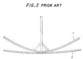
- Fig. 1 is an explanation drawing conceptually showing an earlier technology concerned with a method for bending a steel plate to serve as an outer panel of a ship hull.
- Fig. 2 is a front view showing a wooden pattern for use in the bending in a state in which it is mounted on the steel plate.
- many (10 in the drawing) wooden patterns 1 following frame lines of the outer panel of the ship hull (lines extending along frame materials for the outer panel at positions where the frame materials are attached; the same will hold in the following description) as target shapes are mounted on a steel plate 2.
- each wooden pattern 1 and the steel plate 2 by visual observation, and considers differences between their shapes, e.g., the clearance between the wooden pattern 1 and the steel plate 2. Based on this consideration, the operator studies what position to heat in order to bring the steel plate 2 close to the target shape. As a result, the operator determines each heating position (heating point) . Concretely, the wooden pattern 1 is rolled along the frame line of the steel plate 2 in a vertical plane (the same plane as in Fig. 2). The points of contact of the wooden pattern 1 with the steel plate 2 during the rolling motion are watched to determine the heating points in consideration of the clearance between the wooden pattern 1 and the steel plate 2 in each state.
- heating lines 3 that have been determined are marked on the surface of the steel plate 2 with chalk or the like, and the steel plate 2 is heated with a gas burner along the heating line 3.
- the steel plate 2 is heated with a gas burner by the operator along the heating lines 3 determined by the operator's sense based on many years of experience. As a result, a predetermined curved surface is obtained. Acquiring the ability to determine the heating lines 3 rationally is said to require more than about 5 years of experience. This has posed the problems of the aging and shortage of experienced technicians. The bending procedure also takes a large amount of time for incidental operations, such as the production, mounting and removal of the wooden pattern 1 for the steel plate 2, thus lengthening the entire operating time.
- the finite elements analysis is used, by which destruction is divided in a mesh and material features, along with a shape to be obtained, are input in the program.
- the effects of heating along specific lines are also computed in order to obtain a link between bending forces applied and localized heating.
- JP-A-07 075 835 and JP-A-07 024 534 there is disclosed the determination of heating points being a part of a calculation process taking into account geometric and physical features of the material together with forces applied and heating conditions.
- a method for determining a heating point in the bending of a steel plate which has been subjected to primary bending comprising:
- all the heating points or heating points and bending angles, on a specific line of the steel plate can be determined automatically.
- heating lines and bending angles can be determined simultaneously.
- appropriate heating lines can be prepared automatically on the basis of information on the heating points. Consequently, automatic bending of a predetermined steel plate can be carried out by controlling the position of the heating unit of the high frequency heater on the basis of data on the heating lines.
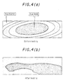
- Figs. 4(a) and 4(b) show, by contour lines, the shapes of a steel plate before and after its heating along heating lines determined by the present invention.
- Fig. 4(a) represents the contour lines before heating, indicating the difference between the shape of the steel plate and the target shape as a difference in color.
- a blue portion at the center of the steel plate has a difference of 5 mm from the target shape, while a red portion at the end of the steel plate has a difference of 50 mm.
- the deviation of the surface shape of the steel plate, the object to be processed, from the target shape is grasped as a geometrical problem mediated by the angle between the base of each isosceles triangle and the base of the adjacent isosceles triangle of the multiplicity of specific isosceles triangles.
- all the heating points on a specific line of the steel plate can be determined automatically.
- Figs. 6(a) to 6(e) are explanation drawings for illustrating an example of processing performed by the heating point determining unit 11.
- the numeral 1' denotes a virtual wooden pattern for illustration
- the numeral 2' represents a similar virtual steel plate.
- the term "virtual” refers to the fact that the wooden pattern or steel plate at issue does not exist as a real one, but exists as electronic data or a graphic expressed in a visible form on the display unit 16.
- the processing in this example is to find the points of contact of the wooden pattern 1' with the steel plate 2' while rolling the wooden pattern 1', to determine a heating point.
- this method we call this method "a contact point finding method".
- the steel plate 2' As shown in Fig. 6(a), the steel plate 2', the object to be bent, is assumed to be one of a curved shape that has been subjected to primary bending. Such steel plate 2', when observed on a minuscule scale, is thought not to have a smoothly varying curved surface, but to be a collection of flat surfaces bent at certain linear sites. For example, as shown in Fig. 6(a), the steel plate 2' forms a flat surface in a certain range beginning on an M line, the centerline in the plate width direction, and is bent at a certain position 1 to have an angle of 10°. On the other hand, a target shape that the wooden pattern 1' has is given in Fig. 6(a).
- the wooden pattern 1' is rolled along a frame line from the initial position shown in Fig. 6(a), whereby the wooden pattern 1' is brought into contact with the steel plate 2' as shown in Fig. 6(b). At this time, contact points on the steel plate 2' are designated as A, B, while contact points on the wooden pattern 1' are designated as C, D. Then, the wooden pattern 1' is rolled in the reverse direction to return it to the initial state (the state shown in Fig. 6(a)) as shown in Fig. 6(c).
- a straight line U connecting the contact points A, B and a straight line V connecting the contact points C, D are obtained to find an intersection point P of the straight lines U, V and an angle ⁇ at which the straight lines U, V intersect.
- a heating point is determined.
- the angle ⁇ (3° in Fig. 6) is deemed as a bending angle at the heating point.
- the intersection point P is extended vertically upward in Fig. 6(d) until it reaches the steel plate 2', to determine a heating position.
- the steel plate 2' is heated at this heating position, whereby it is bent by the angle ⁇ , beginning at the heating position. This is a case shown in Fig. 6 (e).
- this heating results in the contact of the contact point B of the steel plate 2' with the contact point D of the wooden pattern 1', thus bringing the shape of the steel plate 2' close to the target shape (the shape of the wooden pattern 1").
- the intersection point P and the heating position based thereon there is a difference in the Z axis coordinate, the position in the vertical direction
- the lengths of the straight lines U, V ranging from the intersection point P to the contact points B, D are sufficiently large relative to the angle ⁇ .
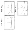
- Figs. 7(a) to 7(c) are explanation drawings conceptually illustrating display screens of the display unit 16 when the heating point is determined by the heating point determining unit 11.
- Fig. 7(a) corresponds to the initial position
- Fig. 7 (b) corresponds to a case in which the wooden pattern 1' is rolled once
- Fig. 7(c) corresponds to a case in which the wooden pattern 1' is rolled twice.
- Fig. 8 is an explanation drawing conceptually showing the blank layout of the steel plate 2, the object to be processed in the instant embodiment.
- a virtual steel plate 2' which is a part of a cylindrical surface with a radius R taken out as in the drawing is assumed in the instant embodiment.
- a roller reference line 16' is defined as indicating the direction of the central axis when the target shape is roughly deemed to be a cylindrical surface.
- Fig. 8 shows a case in which the M line, the centerline in the plate width direction, intersects the roller reference line 16'.
- the roller reference line 16' and the M line are not always in this relation. Since the steel plate 2' forms a part of the outer panel of a ship hull, for example, the roller reference line 16' and the M line may agree in a certain case.
- Figs. 9(a), (b), (c) and (d) are explanation drawings for illustrating an example of processing performed by the heating line determining unit 14. Determination of the heating line in this case is performed by connecting the heating points, which have been determined by the heating point determining unit 11, by a virtual straight line, examining the degree of parallelism between this straight line and a virtual roller line 16" drawn on a virtual steel plate 2', and grouping the heating points, whose straight lines show a predetermined degree of parallelism, into the same group. Grouping is performed while dividing the heating points into those above and those below the roller line 16".
- F 1 to F 7 represent virtual frame lines. The subscripts attached to the symbol F designate the frame line numbers. Many dots indicated narrowly at right angles to the respective frame lines F 1 to F 7 refer to the heating points.
- a starting point 1 is set first of all. From this starting point 1, virtual straight lines (indicated as dashed lines in Fig. 9) are drawn toward the heating points on the respective frame lines F 1 to F 7 . The starting point is established on the frame line of a smaller frame line No. and at a site nearer to the roller line 16".
- FIG. 9(b) shows that the heating points belonging to Group 1 based on the starting point 1 have been fixed, and the heating points based on the starting point 2 are being investigated. On this occasion, the heating points that have already been grouped are neither used as the starting points nor subjected to grouping. In this manner, the heating points lying below the roller line 16" are grouped.
- a straight line (or a curve) is obtained from the sequence of heating points in each group, as shown in Fig. 9(c), and this line is designated as a virtual heating line 3'.
- the heating line 3' is obtained by the method of least squares if it is a straight line, or by spline interpolation or the like if it is a curve.
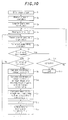
- Fig. 10 is a flow chart showing a concrete procedure (example) using the heating point determining unit 11 when obtaining the heating points by the contact point finding method.
- the heating points are obtained on the frame lines, but needless to say, the way of obtaining them is not restricted to this manner.
- the frame lines are lines corresponding to the positions at which frame materials are attached. Thus, data on their positions are stored as design data. The use of the frame lines in obtaining the heating points is advantageous in the applicability of such data. The above-mentioned procedure will be explained based on Fig. 10.
- the target shape is rolled along the steel plate, but the same effect is obtained if the steel plate is rolled along the target shape. In short, one of them may be rolled relative to the other so that the contact point of the two is obtained.
- the purpose of determining the heating points in the above manner is to obtain the heating positions and heating intensities (quantities of heat given to the steel plate) for causing the necessary change in shape. Between the heating intensity and the angle ⁇ , there is a predetermined relationship, which can be found experimentally. Thus, at a time when the angle ⁇ is found, the heating intensity can be determined (needles to say, if the angle ⁇ is recorded as data, it can be converted to the heating intensity later, where necessary) . Thus, at step S 14 , the heating intensity with respect to the angle ⁇ may be obtained along with data on the angle ⁇ , although this is not directly related to the processing for finding the heating point.
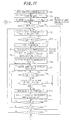
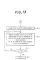
- Figs. 11 to 13 are flow charts showing a concrete procedure (example) using the heating line determining unit 14 when obtaining the heating lines on the basis of the heating points determined. This procedure will be explained based on these drawings.
- Fig. 14 shows an example in which the heating intensity (determined by the bending angle ⁇ ) at each heating point is taken into consideration during the processings illustrated in Fig. 13, and the information on the heating intensity is incorporated into the information on the heating line.
- the distribution of the heating intensity is calculated for the determined heating line by the process subsequent to step S 56 in accordance with the instant embodiment (step S 59 ).
- the heating intensity has been directly obtained separately based on the bending angle ⁇ at the heating point, or is determined on the basis of information on the bending angle ⁇ at the heating point.
- the heating points on each heating line 3 can be heated with the most appropriate quantity of heat.
- this can be easily achieved by controlling an electric current supplied to the high frequency heating coil to control the amount of heat input to the steel plate 2.
- Fig. 15 shows an example in which the heating intensity (determined by the bending angle ⁇ ) at each heating point is taken into consideration during the processings illustrated in Figs. 11 and 12, and this heating intensity is also incorporated into the conditions for grouping.
- the heating intensity is same as the heating intensity at the starting point (the heating intensity includes that within a predetermined tolerance range) (step S 60 ). If this judgment shows that the heating point in question does not have the same heating intensity, this heating point is excluded from the relevant group. In other words, the same group No. as that of the starting point is assigned to the heating point, provided that it has the same heating intensity.
- the heating points on each heating line 3 can be heated with the same quantity of heat.
- the most appropriate amount of heat input to the steel plate can be given by keeping the electric current supplied to the high frequency heating coil constant for a single heating line 3.
- the term "virtual" has been defined as not existing as a real one, but existing as electronic data or a graphic expressed in a visible form on the display unit 16. However, such a restriction need not be applied to the technical idea of the present invention.
- a wooden pattern and a steel plate which an operator prepares by plotting are also included in the concept "virtual” as referred to herein, unless they are real ones.
- Figs. 16 to 18 are explanation drawings for illustrating another example of processing performed by the heating point determining unit 41.
- the processing shown in these drawings focuses on the fact that the curved shape of the steel plate 2 on a predetermined line, such as each frame line, can be regarded as a collection of arcs with a plurality of curvatures.
- the arc of the target shape is compared with the arc of an actually measured shape corresponding to this arc portion on the basis of the curvatures of both arcs. Based on the results of comparison, the heating point is determined. This method is called “the curvature comparison method".
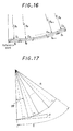
- Figs. 16 and 17 are views for illustrating the principle of the curvature comparison method.
- Fig. 16 shows the curve of the target shape (only its half to the right of M line, the reference line, is shown) divided into fine segments D 1 to D n which are arcs with radii of R 1 to R n .
- Fig. 17 shows a mode in which one of the divisional arcs indicated in Fig. 16 is approximated by a fold line defined by the bases of a plurality of (number m in Fig. 17) congruent isosceles triangles connected together while sharing their equal sides. As shown in Fig.
- the target shape is divided into a plurality of fine segments D 1 to D n , these fine segments D 1 to D n are regarded as arcs, curvatures or radii are designated for the respective segments D 1 to D n , and the lengths l 1 to l n of the arcs of the respective segments D 1 to D n are designated, whereby the target shape can be specified.
- the target shape data 12 in the respective segments D 1 to D n are compared with the steel plate measurement data 13, the amount of deformation of the steel plate 2 for making the target shape and the shape of the steel plate agree can be determined by the difference between the two types of data.
- the deformation in heat bending is bending at the heating points. That is, the arcs in the respective fine segments are approximated by straight lines.
- ⁇ is the angle between the bases of the isosceles triangles.
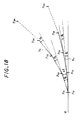
- Fig. 18 is an explanation drawing showing by a two-dot chain line a mode in which the arc of one segment of the target shape is approximated by a fold line N O defined by the bases of the m number of isosceles triangles connected together while sharing their equal sides, and showing by a solid line a mode in which the arc of one segment of the measured shape corresponding to this segment is approximated by a fold line N C defined by the bases of the m number of isosceles triangles connected together while sharing their equal sides.
- ⁇ O is the angle that each subline of the fold line N O forms with the adjacent subline
- ⁇ C is the angle that each subline of the fold line N C forms with the adjacent subline.
- the bending angle at this time is designated as ⁇
- the bending angle ⁇ is given as the difference between the angle formed by the adjacent sublines of the fold line N O and the angle formed by the adjacent sublines of the fold line N C .
- l 0 l C
- the amount of heating e.g., the amount of heat input based on parameters such as an electric current, and the clearance between a high frequency heating coil and the steel plate 2, during high frequency heating
- the heating points are obtained as respective positions found when the length l C is divided by the heating distance (l C /m). That is, if the radius R 0 of the arc of the target shape, the radius R c of the arc of the measured shape corresponding thereto, the length l 0 (length of the segment to be compared) of both arcs, and the bending angle ⁇ are given, then the three-dimensional positional coordinates of the corresponding heating points can be sought as solutions to geometrical problems by computations.
- the equation (7) is equal to calculating the number m of isosceles triangles for the length l 0 of the arc in the isosceles triangles which inscribe in the target shape with radius R 0 and whose adjacent bases form the angle ⁇ .
- the heating distance can be found from the radius R 0 of the target shape and the bending angle ⁇ .
- the heating point determining unit 11 prepares the following data on the basis of the target shape data 12 read in: 1 ⁇ position data on the reference line on each frame line, 2 ⁇ position data on the end of the steel plate 2 as the object to be processed, 3 ⁇ curvature data on the arc in each segment when the curved shape of the steel plate 2 on each frame line is regarded as a collection of arcs with a plurality of curvatures, and 4 ⁇ position data on the point of the boundary between each segment and the adjacent segment.
- the curvature data 3 ⁇ are values designated at the time of designing, or if these values are not designated, the data are calculated using the point sequence data of the target shape data 12.
- data corresponding to 1 ⁇ to 4 ⁇ are compiled from the steel plate shape measurement data 13 as well. At this time, the data 3 ⁇ correspond to the respective segments of the target shape.
- the heating point determining unit 11 processes the data 1 ⁇ to 4 ⁇ on the target shape and the measured shape, and calculates the heating points by the curvature comparison method described based on Figs. 16 to 18.
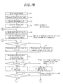
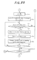
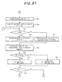
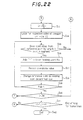
- An example of the relevant concrete procedure will be explained by reference to Figs. 19 to 22.
- Figs. 19 to 22 are flow charts showing this example.
- the heating points are obtained on the frame lines, but needless to say, the way of obtaining them is not restricted to this manner.
- the frame lines are lines corresponding to the positions at which frame materials are attached.
- data on their positions are stored as design data.
- the use of the frame lines in obtaining the heating points is advantageous in the applicability of such data.
- a concrete procedure using the heating line determining unit 14 for determining the heating lines based on the heating points that have been determined by the curvature comparison method is the same as that described in the flow charts for the aforementioned embodiment (Figs. 11 to 13). That is, the three-dimensional data on the heating points on the respective frame lines obtained at step S 19 of Fig. 20 and step S 37 of Fig. 22 are entered for "Enter sequence of heating points" at step S 21 of Fig. 11.
Description
- This invention relates to a method and a system for determining a heating point and a heating line in the bending of a steel plate. More specifically, the invention relates to the method and system useful for application to the bending of a steel plate having complicated curved surfaces, such as an outer panel of a ship hull.
- The outer panel of a ship hull is composed of a steel plate about 10 to 30 mm thick with a complicated undevelopable curved surface which reduces propulsion resistance for efficient navigation in the water. To form this curved outer panel, a processing method generally called line heating has been known for long. This method heats the surface of a steel plate locally by means of a gas burner or the like, to cause the extraplane angular deformation or intraplane shrinkage deformation of the steel plate due to plastic distortion, and skillfully combines these deformations to obtain the desired shape. This method is used at many shipyards.
- Fig. 1 is an explanation drawing conceptually showing an earlier technology concerned with a method for bending a steel plate to serve as an outer panel of a ship hull. Fig. 2 is a front view showing a wooden pattern for use in the bending in a state in which it is mounted on the steel plate. As shown in both drawings, according to the earlier technology, many (10 in the drawing) wooden patterns 1 following frame lines of the outer panel of the ship hull (lines extending along frame materials for the outer panel at positions where the frame materials are attached; the same will hold in the following description) as target shapes are mounted on a steel plate 2. Then, an operator compares the shapes of each wooden pattern 1 and the steel plate 2 by visual observation, and considers differences between their shapes, e.g., the clearance between the wooden pattern 1 and the steel plate 2. Based on this consideration, the operator studies what position to heat in order to bring the steel plate 2 close to the target shape. As a result, the operator determines each heating position (heating point) . Concretely, the wooden pattern 1 is rolled along the frame line of the steel plate 2 in a vertical plane (the same plane as in Fig. 2). The points of contact of the wooden pattern 1 with the steel plate 2 during the rolling motion are watched to determine the heating points in consideration of the clearance between the wooden pattern 1 and the steel plate 2 in each state.
- Then, it is considered how to connect the respective heating points together in order to make the steel plate 2 similar to the target shape. Based on this consideration, a heating line is determined. As shown in Fig. 3, heating lines 3 that have been determined are marked on the surface of the steel plate 2 with chalk or the like, and the steel plate 2 is heated with a gas burner along the heating line 3.
- With the earlier technology as described above, the steel plate 2 is heated with a gas burner by the operator along the heating lines 3 determined by the operator's sense based on many years of experience. As a result, a predetermined curved surface is obtained. Acquiring the ability to determine the heating lines 3 rationally is said to require more than about 5 years of experience. This has posed the problems of the aging and shortage of experienced technicians. The bending procedure also takes a large amount of time for incidental operations, such as the production, mounting and removal of the wooden pattern 1 for the steel plate 2, thus lengthening the entire operating time.
- In the WO-A-94/21402, WO-A-95/02475 and EP-A-0575646 there is disclosed the amount and distribution of heat to be applied to the plate to be bent, in function of the wanted deformation and the material characteristics.
- In order to determine the bending parameters, according to other known documents, the finite elements analysis is used, by which destruction is divided in a mesh and material features, along with a shape to be obtained, are input in the program.
- The effects of heating along specific lines are also computed in order to obtain a link between bending forces applied and localized heating.
- In the JP-A-07 075 835 and JP-A-07 024 534 there is disclosed the determination of heating points being a part of a calculation process taking into account geometric and physical features of the material together with forces applied and heating conditions.
- No indication is given on a simple geometric method for only determining the position of the heating points or lines.
- It is an object of the invention to overcome this shortcoming.
- The problem is solved by a method for determining a heating point in the bending of a steel plate which has been subjected to primary bending, comprising:
- placing a virtual wooden pattern formed from target shape data on a virtual steel plate formed from steel plate shape measurement data, said target shape data being data on a target shape of the steel plate to be bent, and said steel plate shape measurement data being obtained by measuring a surface shape of the steel plate; rolling the wooden pattern or the steel plate along a specific line on the steel plate, such as a frame line, from a predetermined reference position in a plane including a cross section of the steel plate, to bring the wooden pattern and the steel plate into contact at two points, with the contact points on the steel plate being designated as A, B, and the contact points on the wooden pattern being designated as C, D;
- then rolling the wooden pattern or the steel plate in the reverse direction to return it to the reference position; with the wooden pattern or the steel plate being returned to the reference position, obtaining a straight line U connecting the contact points A, B and a straight line V connecting the contact points C, D; and determining a heating point on the projection on the steel plate of a intersection point P of the straight lines U.V.
-
- According to the present invention, all the heating points or heating points and bending angles, on a specific line of the steel plate can be determined automatically.
- Furthermore, heating lines and bending angles (amounts of heating) can be determined simultaneously. Besides, appropriate heating lines can be prepared automatically on the basis of information on the heating points. Consequently, automatic bending of a predetermined steel plate can be carried out by controlling the position of the heating unit of the high frequency heater on the basis of data on the heating lines.
- Figs. 4(a) and 4(b) show, by contour lines, the shapes of a steel plate before and after its heating along heating lines determined by the present invention. Fig. 4(a) represents the contour lines before heating, indicating the difference between the shape of the steel plate and the target shape as a difference in color. A blue portion at the center of the steel plate has a difference of 5 mm from the target shape, while a red portion at the end of the steel plate has a difference of 50 mm. These findings demonstrate that the farther from the center and the nearer the end, the greater a deviation from the target shape becomes. Fig. 4(b), on the other hand, represents the contour lines after heating the steel plate along the heating lines of the present invention. A look at this drawing will show that a blue portion widens, so that the shape approaches the target shape markedly. That is, sufficiently useful heating lines can be determined without the need to use a wooden pattern concerned with earlier technologies.
- 3) Dividing a curve of a target shape of a steel plate to be bent, into a plurality of successive segments; similarly dividing a curve of a measured shape of the steel plate into a plurality of successive segments in correspondence with the curve of the target shape; determining the number of a plurality of congruent isosceles triangles, which are connected together while sharing their equal sides, for each segment on the basis of the radius of a division of the curve in each segment of the target shape of the steel plate, the radius of a division of the curve in each segment of the measured shape of the steel plate, and a separately set bending angle of the steel plate so that when the division of the curve in each segment of the target shape of the steel plate is regarded as an arc, the arc in each segment of the target shape of the steel plate can be approximated by a fold line defined by the bases of the plural congruent isosceles triangles and that when the division of the curve in each segment of the measured shape of the steel plate is regarded as an arc, the arc in each segment of the measured shape of the steel plate can be approximated by a fold line defined by the bases of a plurality of other congruent isosceles triangles which are connected together while sharing their equal sides, the number of the latter isosceles triangles being the same as the number of the former isosceles triangles whose bases constitute the approximating fold line for the target shape; dividing the arc of the measured shape in each segment by the number of the isosceles triangles to form respective points on the arc; and using the respective points on the arc as heating points.
- 4) Having a heating point determining unit which reads in target shape data on a target shape of a steel plate to be bent, and steel plate shape measurement data obtained by measuring a surface shape of the steel plate; divides a curve of the target shape of the steel plate into a plurality of successive segments; similarly divides a curve of the measured shape of the steel plate into a plurality of successive segments in correspondence with the curve of the target shape; determines the number of a plurality of congruent isosceles triangles, which are connected together while sharing their equal sides, for each segment on the basis of the radius of a division of the curve in each segment of the target shape of the steel plate, the radius of a division of the curve in each segment of the measured shape of the steel plate, and a separately set bending angle of the steel plate so that when the division of the curve in each segment of the target shape of the steel plate is regarded as an arc, the arc in each segment of the target shape of the steel plate can be approximated by a fold line defined by the bases of the plural congruent isosceles triangles and that when the division of the curve in each segment of the measured shape of the steel plate is regarded as an arc, the arc in each segment of the measured shape of the steel plate can be approximated by a fold line defined by the bases of a plurality of other congruent isosceles triangles which are connected together while sharing their equal sides, the number of the latter isosceles triangles being the same as the number of the former isosceles triangles whose bases constitute the approximating fold line for the target shape; divides the arc of the measured shape in each segment by the number of the isosceles triangles to form respective points on the arc; and calculates the coordinates of the respective points as heating points.
-
- According to the aspects 3) and 4), the deviation of the surface shape of the steel plate, the object to be processed, from the target shape is grasped as a geometrical problem mediated by the angle between the base of each isosceles triangle and the base of the adjacent isosceles triangle of the multiplicity of specific isosceles triangles. Thus, all the heating points on a specific line of the steel plate can be determined automatically.
-
- Fig. 1 is an explanation drawing conceptually showing an earlier technology concerned with a method for bending a steel plate which will serve as an outer panel of a ship hull;
- Fig. 2 is a front view showing a wooden pattern for use in the bending of a steel plate according to the earlier technology, the wooden pattern being mounted on the steel plate;
- Fig. 3 is a perspective view showing a state in which heating lines determined by the earlier technology are applied to a steel plate;
- Figs. 4(a) and 4(b) are schematic representations of the shape of a steel plate by contour lines for showing the results of experiments on the effects of the present invention;
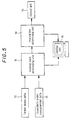
- Fig. 5 is a block diagram showing a system for determining a heating point and a heating line in the bending of a steel plate concerned with an embodiment of the invention;
- Figs. 6(a) to 6(e) are explanation drawings for illustrating an example of processing performed by a heating point determining unit 11 in Fig. 5;
- Figs. 7(a), 7(b) and 7 (c) are explanation drawings showing displays of a display unit 16 associated with processing performed by the heating point determining unit 11 in Fig. 5;
- Fig. 8 is an explanation drawing conceptually showing the blank layout of a steel plate 2, an object to be processed, according to the instant embodiment;
- Fig. 9 is an explanation drawing for illustrating an example of processing performed by a heating line determining unit 14 in Fig. 5;
- Fig. 10 is a flow chart showing an example for determination of heating points;
- Fig. 11 is a flow chart 1 showing a first example for determination of heating lines;
- Fig. 12 is a flow chart 2 showing the first example for determination of heating lines;
- Fig. 13 is a flow chart 3 showing the first example for determination of heating lines;
- Fig. 14 is a flow chart showing part of a second example for determination of heating lines;
- Fig. 15 is a flow chart showing part of a third example for determination of heating lines;
- Fig. 16 is an explanation drawing for illustrating the principle of a curvature comparison method which is processing performed by the heating point determining unit 11 in Fig. 5 (a state in which the curve of a target shape is divided into fine zones that constitute arcs with radii of R1 to Rn);
- Fig. 17 is an explanation drawing for illustrating the principle of the curvature comparison method which is processing performed by the heating point determining unit 11 in Fig. 5 (a state in which one of the arcs of Fig. 22 is approximated by a fold line defined by the bases of a plurality of isosceles triangles connected together while sharing their equal sides);
- Fig. 18 is an explanation drawing for illustrating the principle of the curvature comparison method which is processing performed by the heating point determining unit 11 in Fig. 5 (a comparison between the target shape and the measured shape when approximated by fold lines defined by the bases of a plurality of isosceles triangles) ;
- Fig. 19 is a flow chart 1 showing a further example for determination of heating points;
- Fig. 20 is a flow chart 2 showing the further example for determination of heating points;
- Fig. 21 is a flow chart 3 showing the further example for determination of heating points; and
- Fig. 22 is a flow chart 4 showing the further example for determination of heating points.
-
- Embodiments of the present invention will now be described in detail with reference to the accompanying drawings. However, it is to be understood that these embodiments are given only for illustrative purposes and do not restrict the invention.
- Figs. 6(a) to 6(e) are explanation drawings for illustrating an example of processing performed by the heating point determining unit 11. In these drawings, the numeral 1' denotes a virtual wooden pattern for illustration, and the numeral 2' represents a similar virtual steel plate. The term "virtual" refers to the fact that the wooden pattern or steel plate at issue does not exist as a real one, but exists as electronic data or a graphic expressed in a visible form on the display unit 16. The processing in this example, as has been done by an operator, is to find the points of contact of the wooden pattern 1' with the steel plate 2' while rolling the wooden pattern 1', to determine a heating point. Thus, we call this method "a contact point finding method".
- As shown in Fig. 6(a), the steel plate 2', the object to be bent, is assumed to be one of a curved shape that has been subjected to primary bending. Such steel plate 2', when observed on a minuscule scale, is thought not to have a smoothly varying curved surface, but to be a collection of flat surfaces bent at certain linear sites. For example, as shown in Fig. 6(a), the steel plate 2' forms a flat surface in a certain range beginning on an M line, the centerline in the plate width direction, and is bent at a certain position 1 to have an angle of 10°. On the other hand, a target shape that the wooden pattern 1' has is given in Fig. 6(a). Thus, the wooden pattern 1' is rolled along a frame line from the initial position shown in Fig. 6(a), whereby the wooden pattern 1' is brought into contact with the steel plate 2' as shown in Fig. 6(b). At this time, contact points on the steel plate 2' are designated as A, B, while contact points on the wooden pattern 1' are designated as C, D. Then, the wooden pattern 1' is rolled in the reverse direction to return it to the initial state (the state shown in Fig. 6(a)) as shown in Fig. 6(c).
- With the wooden pattern 1' being returned to the initial state, a straight line U connecting the contact points A, B and a straight line V connecting the contact points C, D are obtained to find an intersection point P of the straight lines U, V and an angle at which the straight lines U, V intersect. Based on this intersection point P, a heating point is determined. The angle (3° in Fig. 6) is deemed as a bending angle at the heating point. Actually, the intersection point P is extended vertically upward in Fig. 6(d) until it reaches the steel plate 2', to determine a heating position. The steel plate 2' is heated at this heating position, whereby it is bent by the angle , beginning at the heating position. This is a case shown in Fig. 6 (e). As shown in this drawing, this heating results in the contact of the contact point B of the steel plate 2' with the contact point D of the wooden pattern 1', thus bringing the shape of the steel plate 2' close to the target shape (the shape of the wooden pattern 1"). Strictly speaking, there is a misalignment between the intersection point P and the heating position based thereon (there is a difference in the Z axis coordinate, the position in the vertical direction) . In the bending at issue, however, the lengths of the straight lines U, V ranging from the intersection point P to the contact points B, D are sufficiently large relative to the angle . Hence, there is practically no harm in handling the intersection point P and the heating position based thereon as the same position.
- Then, the same procedure (the procedure shown in Figs. 6(b) to 6(d)) is performed, provided that the state of contact of the contact point C of the wooden pattern 1' with the contact point A represents a reference position corresponding to the aforementioned initial position. By this measure, a heating point and a bending angle at the heating point are determined. This procedure is repeated until the wooden pattern 1' is rolled to reach the end of the steel plate 2', whereby heating points and bending angles at the heating points are determined sequentially.
- Figs. 7(a) to 7(c) are explanation drawings conceptually illustrating display screens of the display unit 16 when the heating point is determined by the heating point determining unit 11. Fig. 7(a) corresponds to the initial position, Fig. 7 (b) corresponds to a case in which the wooden pattern 1' is rolled once, and Fig. 7(c) corresponds to a case in which the wooden pattern 1' is rolled twice.
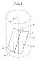
- Fig. 8 is an explanation drawing conceptually showing the blank layout of the steel plate 2, the object to be processed in the instant embodiment. As shown in Fig. 8, a virtual steel plate 2' which is a part of a cylindrical surface with a radius R taken out as in the drawing is assumed in the instant embodiment. To form this cylindrical surface approximately by bending, it is recommendable to bend the surface along the central axis of the cylinder so that its cross section is polygonal. That is, a roller reference line 16' is defined as indicating the direction of the central axis when the target shape is roughly deemed to be a cylindrical surface. Fig. 8 shows a case in which the M line, the centerline in the plate width direction, intersects the roller reference line 16'. The roller reference line 16' and the M line are not always in this relation. Since the steel plate 2' forms a part of the outer panel of a ship hull, for example, the roller reference line 16' and the M line may agree in a certain case.
- Figs. 9(a), (b), (c) and (d) are explanation drawings for illustrating an example of processing performed by the heating line determining unit 14. Determination of the heating line in this case is performed by connecting the heating points, which have been determined by the heating point determining unit 11, by a virtual straight line, examining the degree of parallelism between this straight line and a virtual roller line 16" drawn on a virtual steel plate 2', and grouping the heating points, whose straight lines show a predetermined degree of parallelism, into the same group. Grouping is performed while dividing the heating points into those above and those below the roller line 16". In Fig. 9, F1 to F7 represent virtual frame lines. The subscripts attached to the symbol F designate the frame line numbers. Many dots indicated narrowly at right angles to the respective frame lines F1 to F7 refer to the heating points.
- As shown in Fig. 9(a), a starting point 1 is set first of all. From this starting point 1, virtual straight lines (indicated as dashed lines in Fig. 9) are drawn toward the heating points on the respective frame lines F1 to F7. The starting point is established on the frame line of a smaller frame line No. and at a site nearer to the roller line 16".
- Then, the degree of parallelism, relative to the roller line 16", of each of the virtual straight lines drawn toward the heating points on the respective frame lines F1 to F7 is examined as stated above. The heating points that give the parallel lines or whose straight lines intersect the roller line 16" at angles not larger than a predetermined angle are grouped together into the same group. Fig. 9(a) shows that the heating points of the same group satisfying the requirement for the degree of parallelism based on the starting point 1 are present on the frame lines F3, F4. Upon completion of grouping based on the starting point 1, grouping based on a starting point 2 is performed in accordance with the same procedure, as shown in Fig. 9(b). Fig. 9(b) shows that the heating points belonging to Group 1 based on the starting point 1 have been fixed, and the heating points based on the starting point 2 are being investigated. On this occasion, the heating points that have already been grouped are neither used as the starting points nor subjected to grouping. In this manner, the heating points lying below the roller line 16" are grouped. After grouping work is completed, a straight line (or a curve) is obtained from the sequence of heating points in each group, as shown in Fig. 9(c), and this line is designated as a virtual heating line 3'. The heating line 3' is obtained by the method of least squares if it is a straight line, or by spline interpolation or the like if it is a curve.
- Fig. 10 is a flow chart showing a concrete procedure (example) using the heating point determining unit 11 when obtaining the heating points by the contact point finding method. In the instant embodiment, the heating points are obtained on the frame lines, but needless to say, the way of obtaining them is not restricted to this manner. However, the frame lines are lines corresponding to the positions at which frame materials are attached. Thus, data on their positions are stored as design data. The use of the frame lines in obtaining the heating points is advantageous in the applicability of such data. The above-mentioned procedure will be explained based on Fig. 10.
- 1) Design data such as CAD data are loaded to enter the target shape of the steel plate as three-dimensional data (step S1).
- 2) The shape of the steel plate, the object to be processed, is measured to obtain three-dimensional coordinate data thereon (step S2). This can be easily performed by an existing measuring method, such as laser measurement or image processing of an image shot with a camera.
- 3) The processings at step S4 through step S14 are performed for the respective frame lines (step S3). The expression "Loop ..." indicated in the block for step S3 refers to an operation in which the processings subsequent to the step at issue (in this case, step S3) are deemed to be one loop, and the processings belonging to this loop are sequentially repeated for each frame line, as in the instant embodiment (the same will hold later on) . At step S3, the frame line No. i is designated as "1", and the flow moves to the processing at a next step S4. "FLMAX" means the maximum frame line No. (the same will hold later on).
- 4) Since no heating point exists initially, j=0 is set as the initial value of the heating point No. (step S4).
- 5) The position and posture of the target shape are recorded (step S5). Concretely, records are made, for example, of the coordinates of the reference point of the target shape (the point of intersection between a curve of the frame line showing the target shape and a sight line, i.e., the point of the virtual wooden pattern showing the M line), and the inclination of the sight line (the inclination angle based on the horizontal line or the vertical line). The state on this occasion corresponds to the initial state in which during an operation using a conventional wooden pattern, an operator places the middle point of a portion of the wooden pattern extending along the target shape on the M line of the steel plate, and holds the sight line vertically.
- 6) The target shape is rolled along the steel plate (step S6), and its rolling is repeated until the target shape reaches the end of the steel plate (step S7). When the target shape and the steel plate are detected to have contacted at 2 points during the rolling (S8), the processing described in the aforementioned "principle of the contact point finding method" is performed to determine the coordinates of the intersection point P and its angle (steps S9, S10, S11 and S12).
- 7) "1" is added to the heating point No., and data on the respective heating points on specific frame lines are compiled (steps S13 and S14). These data on the heating points are given as three-dimensional coordinate and angle data with the respective frame line Nos. and the respective heating point Nos. specified.
- 8) When it is detected at the judging step (step S7) that the end of the steel plate has been reached, it is judged whether the frame line No. at this time is larger than the maximum value of the number of the frame lines (FLMAX) for which the heating point determining processings are performed. If the frame line No. i<FLMAX, the processings at steps S4 to S14 are repeated for the frame line of the next No.. Whenever the flow returns to step S4, "1" is added to the frame line No. i. If the frame line No. i≥FLMAX, this means that the predetermined processings for obtaining the heating points have been completed for all the frame lines. Thus, the heating point determining processings are ended (steps S15 and S16).
- 9) When it is not detected by the processing at step S8 that no contact at 2 points has been made, the flow returns to the processing at step S5, and the processing at steps S5 to S7 are repeated. That is, the target shape is rolled at a certain angle by a single processing, and the processings at steps S5 to S7 are repeated until contact at 2 points is detected. Thus, if the shape of the steel plate extending along the frame line for which the heating points are to be determined is a flat plane, it is detected by the processing at step S7 that the end of the steel plate has been reached with no contact point being determined. Thus, a judgment is made that no heating point exists for this frame line, and the flow moves to the processing for the next frame line. If no contact at 2 points has been detected for all the frame lines, namely, if the entire steel plate is of a flat shape, no heating points can be determined by the "contact point finding method". Thus, the steel plate for which heating points should be determined by this method must have been subjected to primary bending with a bending roll or the like.
-
- According to the processing at step S6, the target shape is rolled along the steel plate, but the same effect is obtained if the steel plate is rolled along the target shape. In short, one of them may be rolled relative to the other so that the contact point of the two is obtained. The purpose of determining the heating points in the above manner is to obtain the heating positions and heating intensities (quantities of heat given to the steel plate) for causing the necessary change in shape. Between the heating intensity and the angle , there is a predetermined relationship, which can be found experimentally. Thus, at a time when the angle is found, the heating intensity can be determined (needles to say, if the angle is recorded as data, it can be converted to the heating intensity later, where necessary) . Thus, at step S14, the heating intensity with respect to the angle may be obtained along with data on the angle , although this is not directly related to the processing for finding the heating point.
- Figs. 11 to 13 are flow charts showing a concrete procedure (example) using the heating line determining unit 14 when obtaining the heating lines on the basis of the heating points determined. This procedure will be explained based on these drawings.
- The following processings are performed as shown in Fig. 11:
- 1) Data on the heating points are entered (step S21). Concretely, entry is made of the three-dimensional coordinate and angle data on the respective heating points on the respective frame lines that have been obtained at step S14 of Fig. 10.
- 2) Since no predetermined group is formed initially, g=0 is set as the initial value of the group No. g (step S22).
- 3) The processings at steps S24 to S54 are performed for the respective frame lines (step S23).
- 4) It is judged whether the number of the upper heating points on the frame line of the frame line No. i is HPU(i)>0 (step S24). "The number of the upper heating points, HPU" means the number of the heating points above the roller line 16" found when it is determined whether the heating point is above or below the roller line 16". For example, the heating point with a larger Y coordinate than that of the point of intersection of each frame line and the roller line 16" is regarded as the upper heating point. Thus, if the upper heating point exists, HPU(i)>0. In this case, the flow moves to the processing at step S25.
- 5) The processings at steps S26 to S38 are performed for the respective upper heating points on the frame line of the frame line No. i (step S25). That is, the same processings are carried out for the respective heating points of the heating point Nos. j=1∼HPU(i) to perform their grouping.
- 6) It is judged whether grouping is finished or not (step S26). Concretely, it is judged whether the group No. g is assigned to the heating points that are being judged.
- 7) When the judgment at step S26 shows that the heating points, the objects being judged, have not been grouped, "1" is added to the group No. g (step S27). Since the initial value of the group No. g is "0", the group No. g=1 is given at the processing for the first heating point concerned with the first frame line.
- 8) The heating point, the object being processed, is given the group No. g assigned at step S27 (step S28).
- 9) The number of the heating points belonging to the group is designated as "1" (step S29).
- 10) A starting point is determined by the processings at steps S27 to S29.
- 11) The processings at steps S31 to S37 are performed for the respective frame lines of the frame line Nos. i later than the frame line No. i (step S30). These frame line Nos. are k=(i+1)∼FLMAX.
- 12) The processings at steps S32 to S36 are performed for the respective upper heating points on the frame line of the frame line No. k. (step S31).
- 13) It is judged whether grouping of the specific heating points on the frame line of the frame line No. k is finished or not (step S32). Concretely, it is judged whether the group No. g is assigned to the heating point being judged.
- 14) When the judgment at step S32 shows that the heating point being judged has not been grouped, it is judged whether this heating point is at a position parallel to the roller line 16" when viewed from the starting point (step S33). For example, the heating point as the starting point and the heating point as the object being judged are connected together by a straight line, and the angle of this straight line to the roller line 16" is detected. If this angle is less than a predetermined value, a judgment is made that the heating point in question is at a parallel position. Alternatively, the same judgment car. be made by measuring the distance between each end of the straight line and the roller line 16", and detecting whether the distances measured are each within a certain range.
- 15) When the judgment at step S33 shows that the heating point being judged lies at a position parallel to the roller line 16", this heating point is assigned the same group No. g as that of the heating point as the starting point (step S34).
- 16) "1" is added to the number of the heating points of the group No. g assigned at step S34 (step S35).
- 17) When the processing at step S35 is completed, or when grouping of the heating points being judged by the processing at step S32 is completed, or when the absence of a predetermined degree of parallelism is detected by the processing at step S33, the processings at steps S32 to S35 are repeated (step S36) until the heating point No. 1 of the heating point being judged as belonging to the frame line of the frame line No. k becomes larger than the maximum value HPU(k). Whenever the flow returns from step S36 to step S32, "1" is added to the heating point No.. In this manner, grouping of the heating points on the specific frame line is performed.
- 18) When it is detected by the processing at step S36 that grouping of all the upper heating points on the frame line of the frame line No. k is completed, the processings at steps S31 to S36 are repeated until the frame line No. k becomes larger than the maximum value FLMAX (step S37). Whenever the flow returns from step S37 to step S31, "1" is added to the frame No. k. In this manner, grouping of the upper heating points for all the frame lines of the frame line Nos. later than i is performed.
- 19) When it is judged by the processing at step S26 that grouping of the heating points, the objects being judged, on the frame line of the frame line No. i has been finished, or when it is detected by the processing at step S37 that grouping of the upper heating points for all the frame lines of the frame line Nos. later than i has been finished, the processings at steps S26 to S38 are repeated (step S38) until the heating point No. j of the heating point being judged as belonging to the frame line of the frame line No. i becomes larger than the maximum value HPU(i). Whenever the flow returns from step S38 to step S26, "1" is added to the heating point No.. In this manner, grouping of the upper heating points on the frame line of the frame line No. i is performed. As shown in Fig. 12, the following processings are performed:
- 20) When it is detected by the processing at step S24 that no upper heating points exist on the frame line of the frame line No. i, or when it is detected by the processing at step S38 that grouping of all the upper heating points on the frame line where the starting point belongs is completed, grouping of the lower heating points on each frame line is performed by exactly the same procedure. That is, the processings at steps S39 to S53 corresponding to the processings at steps S24 to S38 are performed for the lower heating points. At step S39, "the number of the lower heating points, HPL" refers to the number of the heating points that is in contrast to the upper heating points when it is determined whether the heating point is above or below the roller line 16". In other words, HPL means the number of the heating points below the roller line 16". For example, the heating point with a smaller Y coordinate than that of the point of intersection of each frame line and the roller line 16" is regarded as the lower heating point.
- 21) When it is detected by the processing at step S39 that no lower heating points exist on the frame line of the frame line No. i, or when it is detected by the processing at step S53 that grouping of all the lower heating points on the frame line where the starting point belongs is completed, it is judged whether the frame line No. is larger than FLMAX. If it is smaller, the processings at steps S24 to S53 are repeated for each frame line. When these processings are completed for all the frame lines, i.e., when grouping of all the heating points belonging to all the frame lines is completed, the flow moves to the next processing (step S54). As shown in Fig. 13, the following processings are performed:
- 22) For each heating point group established, the heating points of each group are sequentially connected together by a straight line, or a straight line or a curve is calculated by the method of least squares, spline interpolation or the like based on the coordinate values of the heating points, thereby to obtain a heating line (steps S55 and S56). At step S55, "GNO" refers to the maximum value of the number of the groups.
- 23) When it is detected that the group No. ≥ GNO, i.e., when it is detected that the heating lines 3 have been determined for all the groups, all the processings are completed (steps S57 and S58).
-
- Fig. 14 shows an example in which the heating intensity (determined by the bending angle ) at each heating point is taken into consideration during the processings illustrated in Fig. 13, and the information on the heating intensity is incorporated into the information on the heating line. As shown in Fig. 14, the distribution of the heating intensity is calculated for the determined heating line by the process subsequent to step S56 in accordance with the instant embodiment (step S59). The heating intensity has been directly obtained separately based on the bending angle at the heating point, or is determined on the basis of information on the bending angle at the heating point.
- According to the instant embodiment, the heating points on each heating line 3 can be heated with the most appropriate quantity of heat. In the case of bending by high frequency heating, for example, this can be easily achieved by controlling an electric current supplied to the high frequency heating coil to control the amount of heat input to the steel plate 2.
- Fig. 15 shows an example in which the heating intensity (determined by the bending angle ) at each heating point is taken into consideration during the processings illustrated in Figs. 11 and 12, and this heating intensity is also incorporated into the conditions for grouping. As shown in Fig. 15, in accordance with the instant embodiment, it is judged by the processing subsequent to step S33 or step S48 whether the heating intensity is same as the heating intensity at the starting point (the heating intensity includes that within a predetermined tolerance range) (step S60). If this judgment shows that the heating point in question does not have the same heating intensity, this heating point is excluded from the relevant group. In other words, the same group No. as that of the starting point is assigned to the heating point, provided that it has the same heating intensity.
- According to the instant embodiment, the heating points on each heating line 3 can be heated with the same quantity of heat. In the case of bending by high frequency heating, for example, the most appropriate amount of heat input to the steel plate can be given by keeping the electric current supplied to the high frequency heating coil constant for a single heating line 3.
- In the above-described embodiments, the term "virtual" has been defined as not existing as a real one, but existing as electronic data or a graphic expressed in a visible form on the display unit 16. However, such a restriction need not be applied to the technical idea of the present invention. A wooden pattern and a steel plate which an operator prepares by plotting are also included in the concept "virtual" as referred to herein, unless they are real ones.
- Figs. 16 to 18 are explanation drawings for illustrating another example of processing performed by the heating point determining unit 41. The processing shown in these drawings focuses on the fact that the curved shape of the steel plate 2 on a predetermined line, such as each frame line, can be regarded as a collection of arcs with a plurality of curvatures. The arc of the target shape is compared with the arc of an actually measured shape corresponding to this arc portion on the basis of the curvatures of both arcs. Based on the results of comparison, the heating point is determined. This method is called "the curvature comparison method".
- Figs. 16 and 17 are views for illustrating the principle of the curvature comparison method. Fig. 16 shows the curve of the target shape (only its half to the right of M line, the reference line, is shown) divided into fine segments D1 to Dn which are arcs with radii of R1 to Rn. Whereas Fig. 17 shows a mode in which one of the divisional arcs indicated in Fig. 16 is approximated by a fold line defined by the bases of a plurality of (number m in Fig. 17) congruent isosceles triangles connected together while sharing their equal sides. As shown in Fig. 16, the target shape is divided into a plurality of fine segments D1 to Dn, these fine segments D1 to Dn are regarded as arcs, curvatures or radii are designated for the respective segments D1 to Dn, and the lengths l1 to ln of the arcs of the respective segments D1 to Dn are designated, whereby the target shape can be specified. Thus, if the target shape data 12 in the respective segments D1 to Dn are compared with the steel plate measurement data 13, the amount of deformation of the steel plate 2 for making the target shape and the shape of the steel plate agree can be determined by the difference between the two types of data. Here, the deformation in heat bending is bending at the heating points. That is, the arcs in the respective fine segments are approximated by straight lines.
- As shown in Fig. 17, when an arc with radius R is approximated by the fold line defined by the bases of the m number of the isosceles triangles connected together while sharing their equal sides, the length 1 of the arc is generally given by the equation (1):
- In the equation (1), is the angle between the bases of the isosceles triangles.
- Fig. 18 is an explanation drawing showing by a two-dot chain line a mode in which the arc of one segment of the target shape is approximated by a fold line NO defined by the bases of the m number of isosceles triangles connected together while sharing their equal sides, and showing by a solid line a mode in which the arc of one segment of the measured shape corresponding to this segment is approximated by a fold line NC defined by the bases of the m number of isosceles triangles connected together while sharing their equal sides. As shown in Fig. 18, straight lines connecting the points (PO1, PO2), (PO2, PO3), (PO3, PO4) ..... make the fold line NO, while straight lines connecting the points (PC1, PC2), (PC2, PC3), (PC3, PC4) ..... make the fold line NC. O is the angle that each subline of the fold line NO forms with the adjacent subline, while C is the angle that each subline of the fold line NC forms with the adjacent subline. Referring to Fig. 18, one will see that when each subline of the fold line based on the measured shape indicated by the solid line is bent by Δ (=O - C), it coincides with each subline of the fold line based on the target shape.
- Let the length of the segment of the target shape and the measured shape of the steel plate 2 to be compared be l0, and the radius of the arc of the target shape in this segment be R0. When this arc is approximated by the fold line NO defined by the bases of the m number of isosceles triangles connected together while sharing their equal sides, the relation of the equation (2) is obtained from the equation (1):
- On the other hand, let the radius of the arc based on the measured shape of the portion corresponding to the segment to be compared be RC. When this arc is approximated by the fold line NC defined by the bases of the m number of isosceles triangles connected together while sharing their equal sides, the relation of the equation (3) is obtained from the equation (1):
- To heat-process the measured shape into the target shape, it is necessary to bend the m number of sublines of the fold line NC for the measured shape in the manner stated earlier. When the bending angle at this time is designated as Δ, the bending angle Δ is given as the difference between the angle formed by the adjacent sublines of the fold line NO and the angle formed by the adjacent sublines of the fold line NC. That is, the bending angle Δ is expressed by the equation (4):
- In heating of a single steel plate 2, its efficiency is high when the amount of heating (e.g., the amount of heat input based on parameters such as an electric current, and the clearance between a high frequency heating coil and the steel plate 2, during high frequency heating) is made constant overall. When the amount of heating is constant, the bending angle Δ is derived from the properties (material, thickness, etc.) of the steel plate 2. That is, a predetermined bending angle Δ is determined by determining the desired amount of heating, and the number m of the sublines of each of the fold lines NO and NC is given by the equation (5):
- This means that if the bending angle Δ is given, it suffices to divide the length lC by the number m calculated from the equation (5). In other words, the heating points are obtained as respective positions found when the length lC is divided by the heating distance (lC/m). That is, if the radius R0 of the arc of the target shape, the radius Rc of the arc of the measured shape corresponding thereto, the length l0 (length of the segment to be compared) of both arcs, and the bending angle Δ are given, then the three-dimensional positional coordinates of the corresponding heating points can be sought as solutions to geometrical problems by computations.
- In case the steel plate 2 is a flat plate, on the other hand, the radius Rc in the equation (5) becomes infinity, so that m cannot be obtained. Thus, the equation (5) is converted into the equation (6):
- Infinitizing Rc in the equation (6) makes (R0/Rc) zero, thus giving the equation (7):
- The equation (7) is equal to calculating the number m of isosceles triangles for the length l0 of the arc in the isosceles triangles which inscribe in the target shape with radius R0 and whose adjacent bases form the angle Δ. In short, when a flat plate is bent, the heating distance can be found from the radius R0 of the target shape and the bending angle Δ.
- To determine the heating points by the above-described curvature comparison method, the heating point determining unit 11 prepares the following data on the basis of the target shape data 12 read in: 1 ○ position data on the reference line on each frame line, 2 ○ position data on the end of the steel plate 2 as the object to be processed, 3 ○ curvature data on the arc in each segment when the curved shape of the steel plate 2 on each frame line is regarded as a collection of arcs with a plurality of curvatures, and 4 ○ position data on the point of the boundary between each segment and the adjacent segment. The curvature data 3 ○ are values designated at the time of designing, or if these values are not designated, the data are calculated using the point sequence data of the target shape data 12. Similarly, data corresponding to 1 ○ to 4 ○ are compiled from the steel plate shape measurement data 13 as well. At this time, the data 3 ○ correspond to the respective segments of the target shape.
- The heating point determining unit 11 processes the data 1 ○ to 4 ○ on the target shape and the measured shape, and calculates the heating points by the curvature comparison method described based on Figs. 16 to 18. An example of the relevant concrete procedure will be explained by reference to Figs. 19 to 22. Figs. 19 to 22 are flow charts showing this example. In this example, the heating points are obtained on the frame lines, but needless to say, the way of obtaining them is not restricted to this manner. However, the frame lines are lines corresponding to the positions at which frame materials are attached. Thus, data on their positions are stored as design data. The use of the frame lines in obtaining the heating points is advantageous in the applicability of such data.
- As shown in Fig. 19, the following processings are performed:
- 1) Design data such as CAD data are loaded to enter the target shape of the steel plate as three-dimensional data, and processings are also performed for the preparation of the data 1 ○ to 4 ○, such as curvature data on the arc in each segment constituting each frame line, and position data on the point of the boundary between each segment and the adjacent segment (step S1).
- 2) The shape of the steel plate 2, the object to be processed, is measured to obtain three-dimensional coordinate data thereon, and processings are also performed for the preparation of the data 1 ○ to 4 ○ as for the target shape (step S2). Measurement of the shape of the steel plate 2 can be easily performed by an existing measuring method, such as laser measurement or image processing of an image shot with a camera.
- 3) The bending angle Δ, a heat deforming angle, is set (step S3).
- 4) The processings at step S5 through step S41 are performed for the respective frame lines (step S4). The expression "Loop ..." indicated in the block for step S4 refers to an operation in which the processings at steps subsequent to the step at issue (in this case, step S4) are regarded as one loop, and the processings belonging to this loop are sequentially repeated for each frame line, as in the instant embodiment (the same will hold later on) . At step S4, the frame line No. i is designated as "1", and the flow moves to the processing at a next step S5. "FLMAX" means the maximum frame line No. (the same will hold later on).
- 5) Since no upper heating point exists initially, "0" is set as the initial value of the heating point No. (step S5). "The upper heating point" means the heating point above a reference line, a straight line heading in the direction of a central axis of a cylinder whose part is deemed to approximate the target shape of the steel plate 2 (e.g., a point above the roller reference line 16' used in the explanation of a heating line determination method to be detailed later based on Fig. 8) when it is determined whether the heating point is above or below the reference line. For example, the heating point with a larger Y coordinate than that of a point on the reference line is regarded as the upper heating point.
- 6) The processings at step S7 to step S22 are performed for the respective segments, DM to DMAX, to be compared (step S6). "DM" denotes the No. of the segment where the M line, the initial reference position, exists. "DMAX" designates the maximum value of the segment No..
- 7) It is judged whether the segment is the segment where the M line, the initial reference position, exists (step S7).
- 8) If the processing at step S7 shows it to be the segment where the M line exists, a judgment is made that the reference point is at the position of the M line. Based on this judgment, this position is set (step S8).
- 9) If the processing at step S7 shows it to be the segment where no M line exists, a judgment is made that the reference point is at the end of the segment nearer to the M line. Based on this judgment, this position is set (step S9).
- 10) The radius RC is found from the measurement data on the relevant segment (step S10).
- 11) It is judged whether Rc is larger than the radius Rmax (step S11). The radius Rmax has been set at a value large enough for the steel plate to be regarded as a flat plate (radius = infinity).
- 12) If the processing at step S11 shows RC > Rmax, the steel plate 2 as the object to be processed is deemed to be a flat plate. Thus, a calculation based on the equation (8) is done to determine the number m of the sublines of a fold line belonging to the relevant segment (step S12).
- 13) If the processing at step S11 shows RC ≤ Rmax, a calculation based on the equation (7) is made to determine the number m of the sublines of a fold line belonging to the relevant segment (step S13). The value of m is treated such that the digits to the right of the decimal point are discarded to give an integer.
- 14) It is judged whether the number m of the sublines is larger than 1 (step S14). As shown in Fig. 20, the following processings are performed:
- 15) If the processing at step S14 shows m > 1, the length l of the heating distance (l = l0/m) is calculated (step S15). If m ≤ 1, this means that two or more sublines are not present in the relevant segment, and there is no apex which should serve as the position of bending. Thus, the procedure moves to the processing for a next segment.
- 16) The processings at steps S17 through S21 are performed for the respective sublines of the fold line belonging to the relevant segment (step S16).
- 17) It is judged whether a point apart from the reference point in the relevant segment by the length 1 of the heating distance exists in this segment (step S17).
- 18) If the processing at step S17 shows the existence of such a point in the segment, "1" is added to the upper heating point No. (step S18). If that processing shows the absence of such a point, the flow moves to the processing for a next segment.
- 19) In addition to the upper heating point No. associated with the processing at step S18, the coordinate value of this heating point is recorded (step S19).
- 20) The reference point is changed to the heating point determined at step S19 (step S20).
- 21) The processings at steps S17 through S20 are repeated until the No. of the subline belonging to the segment becomes k ≥ m (step S21). Each time the flow returns from step S21 to the processing at step S17, "1" is added to the subline No. k.
- 22) If the processing at step S21 shows k ≥ m, if the processing at step S17 shows the absence of a predetermined point in the segment, or if the processing at step S14 shows m ≤ 1, the processings at steps S7 through S21 are repeated until the segment No. becomes j > DMAX (step S22). Each time the flow returns from step S22 to the processing at step S7, "1" is added to the segment No. j. As shown in Figs. 21 and 22, the following processings are performed:
- 23) The same processings as those at steps S5 to S40 are performed for the lower heating points (steps S23 to S40).
- 24) If the processing at step S40 shows j > DM, this means that the upper and lower heating points have been determined for a certain frame line. Thus, the flow returns to the processing at step S5, and the processings at steps S5 through S40 are repeated until i > FLMAX (step S41). Each time the flow returns from step S41 to the processing at step S5, "1" is added to the frame line No. i. When i > FLMAX, all the processings are completed (step S42).
-
- A concrete procedure using the heating line determining unit 14 for determining the heating lines based on the heating points that have been determined by the curvature comparison method is the same as that described in the flow charts for the aforementioned embodiment (Figs. 11 to 13). That is, the three-dimensional data on the heating points on the respective frame lines obtained at step S19 of Fig. 20 and step S37 of Fig. 22 are entered for "Enter sequence of heating points" at step S21 of Fig. 11.
Claims (1)
- A method for determining a heating point in the bending of a steel plate which has been subjected to primary bending, comprising:placing a virtual wooden pattern formed from target shape data on a virtual steel plate formed from steel plate shape measurement data, said target shape data being data on a target shape of the steel plate to be bent, and said steel plate shape measurement data being obtained by measuring a surface shape of the steel plate; rolling the wooden pattern or the steel plate along a specific line on the steel plate, such as a frame line, from a predetermined reference position in a plane including a cross section of the steel plate, to bring the wooden pattern and the steel plate into contact at two points, with the contact points on the steel plate being designated as A, B, and the contact points on the wooden pattern being designated as C, D;then rolling the wooden pattern or the steel plate in the reverse direction to return it to the reference position; with the wooden pattern or the steel plate being returned to the reference position, obtaining a straight line U connecting the contact points A, B and a straight line V connecting the contact points C, D; and determining a heating point on the projection on the steel plate of a intersection point P of the straight lines U.V.
Applications Claiming Priority (12)
| Application Number | Priority Date | Filing Date | Title |
|---|---|---|---|
| JP26374897 | 1997-09-29 | ||
| JP26374897 | 1997-09-29 | ||
| JP26375197 | 1997-09-29 | ||
| JP263748/97 | 1997-09-29 | ||
| JP26375197 | 1997-09-29 | ||
| JP263751/97 | 1997-09-29 | ||
| JP26108898A JP3727784B2 (en) | 1997-09-29 | 1998-09-16 | Method and apparatus for determining heating points and heating lines in steel plate bending |
| JP26108998 | 1998-09-16 | ||
| JP26108998A JP3679932B2 (en) | 1997-09-29 | 1998-09-16 | Method and apparatus for determining heating points and heating lines in steel plate bending |
| JP261089/98 | 1998-09-16 | ||
| JP26108898 | 1998-09-16 | ||
| JP261088/98 | 1998-09-16 |
Publications (3)
| Publication Number | Publication Date |
|---|---|
| EP0904867A2 EP0904867A2 (en) | 1999-03-31 |
| EP0904867A3 EP0904867A3 (en) | 2000-08-02 |
| EP0904867B1 true EP0904867B1 (en) | 2002-04-10 |
Family
ID=27478569
Family Applications (1)
| Application Number | Title | Priority Date | Filing Date |
|---|---|---|---|
| EP98118299A Expired - Lifetime EP0904867B1 (en) | 1997-09-29 | 1998-09-28 | Method and system for determining heating point and heating line in bending of steel plate |
Country Status (6)
| Country | Link |
|---|---|
| US (3) | US6298310B1 (en) |
| EP (1) | EP0904867B1 (en) |
| KR (1) | KR100288414B1 (en) |
| DE (1) | DE69804735T2 (en) |
| DK (1) | DK0904867T3 (en) |
| NO (1) | NO312276B1 (en) |
Families Citing this family (15)
| Publication number | Priority date | Publication date | Assignee | Title |
|---|---|---|---|---|
| US6298310B1 (en) * | 1997-09-29 | 2001-10-02 | Mitsubishi Heavy Industries, Ltd. | Method and system for determining heating point and heating line in bending of steel plate |
| GB0119023D0 (en) * | 2001-08-03 | 2001-09-26 | Norsk Hydro As | Method and apparatus for distorting a workpiece |
| US6992756B1 (en) * | 2002-10-21 | 2006-01-31 | Og Technologies, Inc. | Apparatus and method for movement measurement and position tracking of long, non-textured metal objects at an elevated temperature |
| KR100911498B1 (en) | 2007-05-30 | 2009-08-07 | 삼성중공업 주식회사 | Determination system of heating shape and position for triangle heating and method thereof |
| US20150023387A1 (en) * | 2008-03-31 | 2015-01-22 | Jfe Steel Corporation | Steel plate quality assurance system and equipment thereof |
| US10231289B2 (en) | 2013-11-07 | 2019-03-12 | Illinois Tool Works Inc. | Large scale metal forming |
| US10112227B2 (en) | 2013-11-07 | 2018-10-30 | Illinois Tool Works Inc. | Large scale metal forming control system and method |
| CN104399792B (en) * | 2014-11-28 | 2018-04-27 | 广东工业大学 | A kind of flame forming plate flue point decision method based on Naive Bayes Classifier |
| CN105772551B (en) * | 2016-01-29 | 2018-01-30 | 广东工业大学 | A kind of flame forming plate forming detection method based on Chebyshev inequality |
| JP6859164B2 (en) * | 2017-04-06 | 2021-04-14 | 川崎重工業株式会社 | Deformation processing support system and deformation processing support method |
| CA2986676C (en) * | 2017-11-24 | 2020-01-07 | Bombardier Transportation Gmbh | Method for automated straightening of welded assemblies |
| KR102070158B1 (en) * | 2019-07-24 | 2020-01-28 | 기득산업 주식회사 | System For Forming A Curved Surface On A Plate |
| KR102070160B1 (en) * | 2019-07-24 | 2020-01-28 | 기득산업 주식회사 | System For Forming A Curved Surface On A Plate With Position Control Function And Method Thereof |
| KR102070155B1 (en) * | 2019-07-24 | 2020-01-28 | 기득산업 주식회사 | System For Forming A Curved Surface On A Plate |
| KR102436323B1 (en) * | 2021-04-30 | 2022-08-25 | 한국조선해양 주식회사 | The system which forms the convex for the curved shell of the hull |
Family Cites Families (12)
| Publication number | Priority date | Publication date | Assignee | Title |
|---|---|---|---|---|
| US4120187A (en) | 1977-05-24 | 1978-10-17 | General Dynamics Corporation | Forming curved segments from metal plates |
| JPH06541A (en) * | 1992-06-17 | 1994-01-11 | Ishikawajima Harima Heavy Ind Co Ltd | Linear heating device |
| EP0575646A1 (en) | 1992-06-22 | 1993-12-29 | Aliteco Ag | A method and a device for forming various workpieces |
| JP2666674B2 (en) * | 1993-01-29 | 1997-10-22 | 石川島播磨重工業株式会社 | Method of bending metal plate by linear heating |
| EP0649353A1 (en) | 1993-03-25 | 1995-04-26 | Instytut Podstawowych Problemow Techniki | Method of bending metal objects |
| JP2666685B2 (en) * | 1993-07-12 | 1997-10-22 | 石川島播磨重工業株式会社 | Method of bending metal plate by linear heating |
| PL299688A3 (en) | 1993-07-15 | 1995-01-23 | Pan | Method of bending metal workpieces |
| JP2626496B2 (en) * | 1993-08-26 | 1997-07-02 | 石川島播磨重工業株式会社 | Method of bending metal plate by linear heating |
| JP2666691B2 (en) * | 1993-09-07 | 1997-10-22 | 石川島播磨重工業株式会社 | Method of bending metal plate by linear heating |
| JP3478891B2 (en) * | 1995-01-11 | 2003-12-15 | 末弘 水河 | Manufacturing method of band blade |
| KR100319651B1 (en) * | 1997-09-24 | 2002-03-08 | 마스다 노부유키 | Automatic plate bending system using high frequency induction heating |
| US6298310B1 (en) * | 1997-09-29 | 2001-10-02 | Mitsubishi Heavy Industries, Ltd. | Method and system for determining heating point and heating line in bending of steel plate |
-
1998
- 1998-09-24 US US09/159,758 patent/US6298310B1/en not_active Expired - Fee Related
- 1998-09-28 NO NO19984529A patent/NO312276B1/en not_active IP Right Cessation
- 1998-09-28 EP EP98118299A patent/EP0904867B1/en not_active Expired - Lifetime
- 1998-09-28 DK DK98118299T patent/DK0904867T3/en active
- 1998-09-28 KR KR1019980040341A patent/KR100288414B1/en not_active IP Right Cessation
- 1998-09-28 DE DE69804735T patent/DE69804735T2/en not_active Expired - Fee Related
-
2001
- 2001-04-16 US US09/834,604 patent/US6385556B1/en not_active Expired - Fee Related
-
2002
- 2002-02-04 US US10/061,250 patent/US6456957B1/en not_active Expired - Fee Related
Also Published As
| Publication number | Publication date |
|---|---|
| US6385556B1 (en) | 2002-05-07 |
| US20020107656A1 (en) | 2002-08-08 |
| EP0904867A3 (en) | 2000-08-02 |
| US6456957B1 (en) | 2002-09-24 |
| NO312276B1 (en) | 2002-04-22 |
| NO984529D0 (en) | 1998-09-28 |
| KR100288414B1 (en) | 2001-05-02 |
| EP0904867A2 (en) | 1999-03-31 |
| US6298310B1 (en) | 2001-10-02 |
| US20020032542A1 (en) | 2002-03-14 |
| DE69804735T2 (en) | 2002-10-02 |
| NO984529L (en) | 1999-03-30 |
| KR19990030211A (en) | 1999-04-26 |
| DE69804735D1 (en) | 2002-05-16 |
| DK0904867T3 (en) | 2002-07-01 |
Similar Documents
| Publication | Publication Date | Title |
|---|---|---|
| EP0904867B1 (en) | Method and system for determining heating point and heating line in bending of steel plate | |
| EP0904866B1 (en) | Automatic plate bending system using high frequency induction heating | |
| EP1747076B1 (en) | Method and apparatus for optimizing forging processes | |
| EP0955105B1 (en) | Bending order selecting method in bending machine and apparatus therefor | |
| JP4585165B2 (en) | Method of manufacturing metal plate having curved surface, apparatus for manufacturing the same, and metal plate having curved surface | |
| GB2325066A (en) | Generating and veryifying die shape data for making automobile body parts | |
| JP3727784B2 (en) | Method and apparatus for determining heating points and heating lines in steel plate bending | |
| JP2859124B2 (en) | Surface strain judgment method | |
| US7162398B2 (en) | Method for evaluating the dynamic perspective distortion of a transparent body and method for supporting the designing of a three-dimensionally curved shape of a transparent body | |
| JP3679932B2 (en) | Method and apparatus for determining heating points and heating lines in steel plate bending | |
| JP2000237826A (en) | Extension shape selection method of metal plate for bending | |
| JP2927995B2 (en) | Evaluation method of the opening inclination angle of the minute depression on the metal plate surface | |
| JP2002277236A (en) | Tolerance deciding method | |
| JP4252371B2 (en) | Method and apparatus for positioning and arrangement of bending angle detection sensor in bending machine, and control method of bending machine using the bending angle detection sensor | |
| JPH11267869A (en) | Method and device for manufacturing welding pipe | |
| JPH10103921A (en) | Measuring method for cross section of work by optical cutting method | |
| JPH10232110A (en) | Method for measuring work by optical cutting method | |
| CN117387487A (en) | Structure light marking method using free-placed single-cylinder target | |
| JPH0682224A (en) | Inspector for transparent plate-shaped body | |
| JP2908078B2 (en) | Measuring method of depth distribution of micro annular groove | |
| EP0265703A2 (en) | Method for the automatic inspection of channelled panels | |
| JPH0639440A (en) | Data preparing method for radius bending | |
| JPS62114812A (en) | Slat recovery method for steel sheet and device thereof | |
| GB2332963A (en) | Method of generating shape data and method of verifying shape data |
Legal Events
| Date | Code | Title | Description |
|---|---|---|---|
| PUAI | Public reference made under article 153(3) epc to a published international application that has entered the european phase |
Free format text: ORIGINAL CODE: 0009012 |
|
| 17P | Request for examination filed |
Effective date: 19981026 |
|
| AK | Designated contracting states |
Kind code of ref document: A2 Designated state(s): DE DK FR GB IT NL |
|
| AX | Request for extension of the european patent |
Free format text: AL;LT;LV;MK;RO;SI |
|
| PUAL | Search report despatched |
Free format text: ORIGINAL CODE: 0009013 |
|
| RIC1 | Information provided on ipc code assigned before grant |
Free format text: 7B 21D 11/20 A, 7B 21D 5/00 B |
|
| AK | Designated contracting states |
Kind code of ref document: A3 Designated state(s): AT BE CH CY DE DK ES FI FR GB GR IE IT LI LU MC NL PT SE |
|
| AX | Request for extension of the european patent |
Free format text: AL;LT;LV;MK;RO;SI |
|
| 17Q | First examination report despatched |
Effective date: 20001204 |
|
| AKX | Designation fees paid |
Free format text: DE DK FR GB IT NL |
|
| GRAG | Despatch of communication of intention to grant |
Free format text: ORIGINAL CODE: EPIDOS AGRA |
|
| GRAG | Despatch of communication of intention to grant |
Free format text: ORIGINAL CODE: EPIDOS AGRA |
|
| GRAH | Despatch of communication of intention to grant a patent |
Free format text: ORIGINAL CODE: EPIDOS IGRA |
|
| GRAH | Despatch of communication of intention to grant a patent |
Free format text: ORIGINAL CODE: EPIDOS IGRA |
|
| REG | Reference to a national code |
Ref country code: GB Ref legal event code: IF02 |
|
| GRAA | (expected) grant |
Free format text: ORIGINAL CODE: 0009210 |
|
| AK | Designated contracting states |
Kind code of ref document: B1 Designated state(s): DE DK FR GB IT NL |
|
| REF | Corresponds to: |
Ref document number: 69804735 Country of ref document: DE Date of ref document: 20020516 |
|
| REG | Reference to a national code |
Ref country code: DK Ref legal event code: T3 |
|
| ET | Fr: translation filed | ||
| PLBE | No opposition filed within time limit |
Free format text: ORIGINAL CODE: 0009261 |
|
| STAA | Information on the status of an ep patent application or granted ep patent |
Free format text: STATUS: NO OPPOSITION FILED WITHIN TIME LIMIT |
|
| 26N | No opposition filed |
Effective date: 20030113 |
|
| PGFP | Annual fee paid to national office [announced via postgrant information from national office to epo] |
Ref country code: FR Payment date: 20030909 Year of fee payment: 6 |
|
| PGFP | Annual fee paid to national office [announced via postgrant information from national office to epo] |
Ref country code: DK Payment date: 20030915 Year of fee payment: 6 |
|
| PGFP | Annual fee paid to national office [announced via postgrant information from national office to epo] |
Ref country code: NL Payment date: 20030922 Year of fee payment: 6 |
|
| PGFP | Annual fee paid to national office [announced via postgrant information from national office to epo] |
Ref country code: GB Payment date: 20030924 Year of fee payment: 6 |
|
| PGFP | Annual fee paid to national office [announced via postgrant information from national office to epo] |
Ref country code: DE Payment date: 20031009 Year of fee payment: 6 |
|
| PG25 | Lapsed in a contracting state [announced via postgrant information from national office to epo] |
Ref country code: GB Free format text: LAPSE BECAUSE OF NON-PAYMENT OF DUE FEES Effective date: 20040928 |
|
| PG25 | Lapsed in a contracting state [announced via postgrant information from national office to epo] |
Ref country code: DK Free format text: LAPSE BECAUSE OF NON-PAYMENT OF DUE FEES Effective date: 20040930 |
|
| PG25 | Lapsed in a contracting state [announced via postgrant information from national office to epo] |
Ref country code: NL Free format text: LAPSE BECAUSE OF NON-PAYMENT OF DUE FEES Effective date: 20050401 Ref country code: DE Free format text: LAPSE BECAUSE OF NON-PAYMENT OF DUE FEES Effective date: 20050401 |
|
| GBPC | Gb: european patent ceased through non-payment of renewal fee |
Effective date: 20040928 |
|
| PG25 | Lapsed in a contracting state [announced via postgrant information from national office to epo] |
Ref country code: FR Free format text: LAPSE BECAUSE OF NON-PAYMENT OF DUE FEES Effective date: 20050531 |
|
| NLV4 | Nl: lapsed or anulled due to non-payment of the annual fee |
Effective date: 20050401 |
|
| REG | Reference to a national code |
Ref country code: DK Ref legal event code: EBP |
|
| REG | Reference to a national code |
Ref country code: FR Ref legal event code: ST |
|
| PG25 | Lapsed in a contracting state [announced via postgrant information from national office to epo] |
Ref country code: IT Free format text: LAPSE BECAUSE OF NON-PAYMENT OF DUE FEES Effective date: 20050928 |