EP0868231B1 - A unit for rolling pipes on a mandrel - Google Patents
A unit for rolling pipes on a mandrel Download PDFInfo
- Publication number
- EP0868231B1 EP0868231B1 EP96934600A EP96934600A EP0868231B1 EP 0868231 B1 EP0868231 B1 EP 0868231B1 EP 96934600 A EP96934600 A EP 96934600A EP 96934600 A EP96934600 A EP 96934600A EP 0868231 B1 EP0868231 B1 EP 0868231B1
- Authority
- EP
- European Patent Office
- Prior art keywords
- rolling
- axis
- roll
- rolling mill
- unit
- Prior art date
- Legal status (The legal status is an assumption and is not a legal conclusion. Google has not performed a legal analysis and makes no representation as to the accuracy of the status listed.)
- Expired - Lifetime
Links
- 238000005096 rolling process Methods 0.000 title claims abstract description 230
- 239000000969 carrier Substances 0.000 claims abstract description 24
- 230000001105 regulatory effect Effects 0.000 claims 1
- 230000000694 effects Effects 0.000 description 8
- 238000012423 maintenance Methods 0.000 description 6
- 125000006850 spacer group Chemical class 0.000 description 5
- 238000010276 construction Methods 0.000 description 4
- 230000007246 mechanism Effects 0.000 description 3
- 230000008901 benefit Effects 0.000 description 2
- 238000006073 displacement reaction Methods 0.000 description 2
- 230000009471 action Effects 0.000 description 1
- 230000002411 adverse Effects 0.000 description 1
- 230000004075 alteration Effects 0.000 description 1
- 230000005540 biological transmission Effects 0.000 description 1
- 230000015572 biosynthetic process Effects 0.000 description 1
- 230000002301 combined effect Effects 0.000 description 1
- 230000008878 coupling Effects 0.000 description 1
- 238000010168 coupling process Methods 0.000 description 1
- 238000005859 coupling reaction Methods 0.000 description 1
- 230000002349 favourable effect Effects 0.000 description 1
- 230000002452 interceptive effect Effects 0.000 description 1
- 238000000034 method Methods 0.000 description 1
- 230000036961 partial effect Effects 0.000 description 1
- 230000000284 resting effect Effects 0.000 description 1
- 230000000452 restraining effect Effects 0.000 description 1
- 230000002441 reversible effect Effects 0.000 description 1
Images


Classifications
-
- B—PERFORMING OPERATIONS; TRANSPORTING
- B21—MECHANICAL METAL-WORKING WITHOUT ESSENTIALLY REMOVING MATERIAL; PUNCHING METAL
- B21B—ROLLING OF METAL
- B21B25/00—Mandrels for metal tube rolling mills, e.g. mandrels of the types used in the methods covered by group B21B17/00; Accessories or auxiliary means therefor ; Construction of, or alloys for, mandrels or plugs
- B21B25/02—Guides, supports, or abutments for mandrels, e.g. carriages or steadiers; Adjusting devices for mandrels
-
- B—PERFORMING OPERATIONS; TRANSPORTING
- B21—MECHANICAL METAL-WORKING WITHOUT ESSENTIALLY REMOVING MATERIAL; PUNCHING METAL
- B21B—ROLLING OF METAL
- B21B17/00—Tube-rolling by rollers of which the axes are arranged essentially perpendicular to the axis of the work, e.g. "axial" tube-rolling
- B21B17/02—Tube-rolling by rollers of which the axes are arranged essentially perpendicular to the axis of the work, e.g. "axial" tube-rolling with mandrel, i.e. the mandrel rod contacts the rolled tube over the rod length
- B21B17/04—Tube-rolling by rollers of which the axes are arranged essentially perpendicular to the axis of the work, e.g. "axial" tube-rolling with mandrel, i.e. the mandrel rod contacts the rolled tube over the rod length in a continuous process
-
- B—PERFORMING OPERATIONS; TRANSPORTING
- B21—MECHANICAL METAL-WORKING WITHOUT ESSENTIALLY REMOVING MATERIAL; PUNCHING METAL
- B21B—ROLLING OF METAL
- B21B13/00—Metal-rolling stands, i.e. an assembly composed of a stand frame, rolls, and accessories
- B21B13/08—Metal-rolling stands, i.e. an assembly composed of a stand frame, rolls, and accessories with differently-directed roll axes, e.g. for the so-called "universal" rolling process
- B21B13/10—Metal-rolling stands, i.e. an assembly composed of a stand frame, rolls, and accessories with differently-directed roll axes, e.g. for the so-called "universal" rolling process all axes being arranged in one plane
- B21B13/103—Metal-rolling stands, i.e. an assembly composed of a stand frame, rolls, and accessories with differently-directed roll axes, e.g. for the so-called "universal" rolling process all axes being arranged in one plane for rolling bars, rods or wire
-
- B—PERFORMING OPERATIONS; TRANSPORTING
- B21—MECHANICAL METAL-WORKING WITHOUT ESSENTIALLY REMOVING MATERIAL; PUNCHING METAL
- B21B—ROLLING OF METAL
- B21B2203/00—Auxiliary arrangements, devices or methods in combination with rolling mills or rolling methods
- B21B2203/06—Cassettes
-
- B—PERFORMING OPERATIONS; TRANSPORTING
- B21—MECHANICAL METAL-WORKING WITHOUT ESSENTIALLY REMOVING MATERIAL; PUNCHING METAL
- B21B—ROLLING OF METAL
- B21B31/00—Rolling stand structures; Mounting, adjusting, or interchanging rolls, roll mountings, or stand frames
- B21B31/08—Interchanging rolls, roll mountings, or stand frames, e.g. using C-hooks; Replacing roll chocks on roll shafts
-
- B—PERFORMING OPERATIONS; TRANSPORTING
- B21—MECHANICAL METAL-WORKING WITHOUT ESSENTIALLY REMOVING MATERIAL; PUNCHING METAL
- B21B—ROLLING OF METAL
- B21B35/00—Drives for metal-rolling mills, e.g. hydraulic drives
- B21B35/02—Drives for metal-rolling mills, e.g. hydraulic drives for continuously-operating mills
- B21B35/04—Drives for metal-rolling mills, e.g. hydraulic drives for continuously-operating mills each stand having its own motor or motors
Definitions
- the invention relates to a unit for rolling pipes on a mandrel, of the type indicated in the preamble to the first claim hereinbelow appended; the invention also relates to a rolling mill which comprises a plurality of these rolling units.
- the rolling units referred to above in addition to the rolling mills formed by these rolling units arranged in alignment along a longitudinal rolling axis, are already known from the Applicant's Italian patent No IT-B-1254864 (corresponding also to European patent application Nos. EP-A-0565772 and EP-A-0593709); in short, this rolling unit permits the use of at least three driven processing rolls, combining the advantageous effects resulting from this fact with considerable functional flexibility which facilitates the various maintenance and roll-replacement operations.
- the rolls are mounted on a suitable carrier which can be removed from the structure of the rolling mill, and that the rolls are arranged on pivoting lever arms so that their distance from the rolling axis can be adjusted; in a rolling mill of this type, the stresses generated during the rolling of a pipe fitted on a mandrel are transmitted to the outer load-bearing structure by the elements which support the rolls on each arm, through the device for adjusting the positions of the rolls; the load-bearing structure is constituted, for each rolling unit of the rolling mill, by at least two plate-like elements in the form of circular rings joined together by a series of spacers, these elements rigidly supporting a fixed portion of the device for adjusting each roll.
- the outer load-bearing structure is therefore substantially tubular and can effectively absorb the rolling stresses mentioned, precisely by virtue of its closed shape concentric with the rolling axis.
- the rolling mill Maintenance of the rolling mill or changing of the rolls, for example, in order to turn them again, are carried out by the removal of all of the roll carriers from the structure of the rolling mill, the carriers being slid axially relative to the structure on suitable guides provided therein and then deposited on a carriage , arranged at the output end of the rolling mill for moving the carriers; in a solution of this type, the space downstream of the rolling mill has to be at least equal to the length of the pack of carriers inside the rolling mill to allow the carriers to be positioned on the carriage for moving them.
- the outer structure of the rolling unit is substantially "C"-shaped, that is, open on one side in a radial direction relative to the rolling axis; for rolling-mill maintenance and roll-replacement operations, the carriers on which the rolls are mounted are removed from the load-bearing structure in the aforementioned radial direction by being slid on suitable guides provided in each rolling unit.
- This second technical solution is particularly suitable for processing pipes or even rod-shaped bodies and bars, wherein which a mandrel is not used since, because the load-bearing structure of each rolling unit is open laterally, it does not offer the same capacity as the substantially tubular structure described above to contain the rolling stresses mentioned which are transmitted from the mandrel by means of the rolls and the support elements mounted on the pivoting arms.
- the object of the present invention is to devise a rolling unit, as well as a respective rolling mill formed by a plurality of such units, which have structural and functional characteristics such as to combine the advantageous effects demonstrated by the embodiments of the two applications mentioned above; in other words, the invention envisages the provision of a rolling unit and of a respective rolling mill which can contain and withstand the stresses that act on the outer load-bearing structure as a result of the use of the mandrel during rolling, as well as enabling maintenance and roll-changing operations to be carried out by the lateral removal of the respective support carriers from the outer load-bearing structure.
- a rolling mill for processing pipes on a mandrel is generally indicated at 1; it has an outer structure 2 which is disposed concentrically to a rolling axis L and is supported on a base B; the structure 2 is constituted by a plurality of plate-like elements 3 which, as will be described further below, are connected rigidly to one another by means of tie rods 4 and are part of the respective outer structures of a plurality of rolling units 5 aligned along the longitudinal axis L between an input end 6 and an output end 7 for the pipes being processed. These ends 6 and 7 are at opposite ends of the structure 2, respectively.
- each rolling unit 5 comprises a pair of plate-like elements 3 disposed side by side and connected to one another by the tie rods 4 in the general structure 2; more particularly, in this embodiment, the plate-like elements 3 are in the form of substantially circular rings or, in any case, closed rings, on the outer edges of which there are some appendix 8 which will be considered further below, together with other structural details of the invention; in practice, therefore, two consecutive, rigidly interconnected elements 3 in the rolling mill define an outer support structure of each rolling unit.
- all of the rolling units with the respective support structures are connected to one another without loss of continuity and the two faces of a single plate-like element 3 are therefore parts of respective adjacent units along the rolling axis L.
- Each rolling unit 5 has a respective roll carrier 10 in the form of a substantially triangular, or in any case closed, annular frame which is housed between two consecutive plate-like elements 3 in the rolling mill 1; for each rolling unit there are also removable means for locking the carrier in the working position adopted during the rolling of a pipe.
- pins 11, 12, 13 are fixed to each roll carrier 10 at the vertices of an equilateral triangle inscribed in the cross-section of the carrier and respective lever arms 19, 20, 21 are mounted thereon.
- the pins 11, 12, 13 constitute fulcrums about which the corresponding lever arms 19, 20, 21 pivot and are fixed to the roll carrier 10 in a known adjustable manner for which reference should be made to the patent applications of the prior art already cited.
- This teaching in fact prevents the longitudinal elongation of the arms due to the high temperatures which sometimes occur during rolling from adversely affecting the positioning of the rolls relative to the axis L; on the basis of this teaching, the pivoting of the lever arms 19, 20, 21 in fact always takes place in the radial planes mentioned, which are perpendicular to those where the arms pivot in the embodiment shown in the drawings, even in the event of their elongation due to thermal deformation.
- the support elements are mounted on the ends of the arms in a frontally adjustable manner; an example of this adjustable mounting is described and claimed in ITALIAN PATENT No. IT-B-1254864 already cited, where it is achieved by means of bolts and slotted holes (see Figure 3 of this application) which are also applicable in this case; naturally, however, other solutions should not be excluded.
- each roll 27, 28 or 29 in each rolling unit 5 there is a device 30, 31 or 32 for adjusting the distance of the respective axis of rotation A1, A2 or A3 from the rolling axis L; this device acts on support means of the rolls 27, 28, 29 which, as seen above, include the arms 19, 20, 21 with the support elements 24, 25, 26.
- the adjustment devices 30, 31, 32 are preferably hydraulic and each comprises an oleodynamic cylinder-piston unit constituted essentially by a respective fixed portion, 30a, 31a or 32a connected rigidly to the outer structure 2 of the rolling mill between a pair of adjacent plate-like elements 3 in the region of the appendix 8 on the outer edges thereof, and a movable portion 30b, 31b or 32b which can slide back and forth relative to the aforesaid fixed portion along a radial axis passing through the rolling axis L and arranged at 120° to the other two homologous axes.
- the adjustment device 31 that its fixed portion 31a is mounted rotatably on a pin 31c fixed between two plate-like elements 3 of a rolling unit 5; this adjustment device 31 is associated with an actuator 31d acting on the fixed portion 31a in order to rotate the latter about the pin 31c between an operative position in which the movable portion 31b is slidable along the radial axis extending through the rolling axis and arranged at 120° to the other two mentioned above, and an inoperative position in which the adjustment device 31 is retracted relative to a pair of guides 15 arranged transverse the rolling axis.
- These guides extend parallel to one another and are fixed to respective plate-like elements 3 of a rolling unit; the direction of sliding of the movable portion 31b is thus defined when the fixed portion 31a is in the operative position.
- each adjustment device acts on a spacer 24a, 25a or 26a of each support element 24, 25 or 26, the spacer extending through a corresponding hole 33 passing through the roll carrier 10, throughout its thickness, and is situated at a respective vertex of the triangular shape of the carrier.
- suitable biasing means 34 of known type, constituted by a lever mechanism operated by a small hydraulic cylinder, compensate for the weight of each roll 27, 28 and 29 as well as that of the respective support elements and of the support arms 19, 20 and 21.
- the biasing means 34 associated with the arm 20, that is, the arm on which the adjustment device 31 acts can move from the arrangement in which it holds the roll in the rest position, in order to allow the corresponding carrier 10 to come out.
- the roll carriers 10 are housed in the structure 2 of the rolling mill of the invention in a manner such that, as already stated, the sliding axes of the movable portions 30b, 31b and 32b of the adjustment devices associated with a roll carrier 10 are disposed at 120° to one another and are offset by 60° relative to the analogous axes of the movable portions of the devices 30, 31 and 32 associated with the adjacent roll carrier in the rolling mill.
- the rolling mill 1 there is also a mandrel 40 which is moveable along the rolling axis L and is driven by a mandrel-holder 41 shown schematically in Figure 1; in this embodiment, the rolling mill is of the type with a mandrel held by means of a shaped tang 40a provided for connection to the mandrel-holder 41.
- each rolling unit 5 of the rolling mill 1 has linear guides 15 which extend transverse the rolling axis L and lie in a plane inclined at an angle ⁇ of 30° to a horizontal plane extending through the aforementioned rolling axis; moreover, the guides 15 of one unit extend from the opposite side of the rolling mill to those of the adjacent rolling unit.
- the direction in which the guides 15 extend and, more generally, that in which a roll carrier 10 slides, are advantageously parallel to the axis of rotation A1, A2, or A3 of one of the rolls 27, 28 and 29.
- Each roll carrier 10 has wheels 48 to facilitate its running along the guides 15 and, beside each rolling unit, on the side on which the guides 15 extend, there is a device 50 for loading-unloading roll carriers, associated with an extractor 45; the latter is constituted essentially by a thrust element acting parallel to the guides 15 and having an engagement end 45a which engages an appendix 46 of matching shape on the roll carrier.
- the loading-unloading device 50 of each rolling unit has a carriage 51 movable on rails 52 parallel to the rolling axis L; the carriage 51 has two tiltable platforms 53 and 53a operated by respective oleodynamic lifters 54. On the platforms 53 and 53a there are pairs of linear guides 55 and 55a which, when the corresponding platform 53 or 53a is tilted through an angle of 30° relative to a horizontal plane extending through the rolling axis, are coplanar with the guides 15 of the associated rolling unit.
- a mandrel-support apparatus 80 with which the rolling mill of the invention is provided will now be described with reference to Figures 6, 7 and 8; more precisely, the rolling mill has several of these devices disposed between two rolling units 5 of the rolling mill and close to the input end 6 and to the output end 7 for the pipes being processed.
- the apparatus 80 comprises a substantially L-shaped body 81 which can swing transversely relative to the rolling mill and in which there is a seat 86 where three idle mandrel-support rolls 82, 83 and 84 are journalled, these rolls being mounted in association with an articulated system 85 causing them to move from an operative position in which they support a mandrel extending through the apparatus, to an inoperative position in which the rolls are moved away from the rolling axis so as not to interfere with a pipe during rolling.
- the apparatus 80 also includes a stop element 87 for keeping the swinging body 81 in an operative position, that is, in a position in which the seat 86 is concentric with the axis L so that the rolls 82, 83, and 84 can be arranged circumferentially on a mandrel interposed between them, and a rest position in which the body 81 is moved away from the rolling axis. It is hardly necessary to point out that the swinging movement of the body 81 is brought about by means of a hydraulic actuator 88 but, naturally, could be achieved by any other suitable means.
- each rolling unit 5 is driven by respective independent motors 90 together with drive extensions 91, the latter being connected mechanically to the former by couplings, not shown in detail in the drawings, which enable the extensions to be moved axially by means of the hydraulic actuators M, as will be explained further in connection with the operation of the invention which will be described below; before proceeding with this description, it is stated solely that, in the rolling mill of the invention, there are means for adjusting and controlling the various rolling stages, that are not described in detail and the functions of which can in any case be inferred from the explanation given below.
- a pipe to be rolled is inserted from the input end 6 of the rolling mill, fitted on the mandrel 40; it is then advanced along the rolling axis by the rotation of the rolling rolls of each unit with which it comes into contact in succession. More particularly, the rolls of each rolling unit are held in predetermined positions by the combined effect of the biasing means 34 and of the adjustment device 30, 31, 32, the movable portions of which act on the spacers 24a, 25a, 26a of the corresponding support elements 24, 25, 26.
- each rolling unit formed thereby is best able to withstand the aforementioned rolling stresses, thus contributing to the achievement of the first part of the object set at the beginning.
- the means for clamping a carrier in its working position which is occupied during rolling are released so that a roll carrier 10 can slide along the guides 15 of the respective unit; at this stage, the biasing means 34 are also de-activated and those associated with the arm 20 in particular are translated so as not to interfere with the carrier to be removed.
- the extensions 91 for driving the rolls are also disconnected therefrom and are retracted axially by the hydraulic actuators M so as to be moved out of the roll carrier.
- the adjustment device 31 is placed in the retracted position relative to the guides 15 so as not to interfere with the movement of the carrier along them.
- the thrust element 45 is activated to move the roll carrier to be removed along the guides 15 until it is brought to their ends where the platform 53 of the carriage 51 associated with the rolling unit has in the meantime been tilted; the carrier is then placed on the tilted platform and, after it has been fully loaded thereon, the lifter 54 is lowered so as to bring the platform, with the roll carrier resting on it, to a horizontal position.
- the carriage 51 is then advanced so as to bring the second platform 53a, on which the new roll carrier to be inserted is disposed, to a position such that the guides 55a are in alignment with those of the roll unit; the new carrier is then inserted in the rolling unit in the place of that to be replaced by the repetition, in reverse, of the steps just described for the removal of the carrier to be replaced.
- a further and considerable advantage achieved by the invention lies in the fact that the axial stresses which arise during rolling, that is, the stresses having resultants parallel to the rolling axis L and which, although smaller than the radial stresses considered above, may assume quite significant values, are absorbed by the outer structure of each rolling unit.
- the axial stresses mentioned tend to displace the support elements of the rolls, and consequently also the respective roll carriers, in the direction of advancement of the pipe along the rolling axis L; as shown in Figure 4, the tendency of each support element 24, 25 or 26, as well as that of the carrier itself, to move is limited by the plate-like elements 3 adjacent the carrier 10 on which each roll is mounted.
- each support element and of the roll carriers can take place both when the arms 19, 20, 21 pivot in a plane perpendicular to the rolling axis L and in the alternative embodiment mentioned above, wherein the arms are configured so as to pivot in radial planes extending through this rolling axis.
- Another advantage achieved by the present invention that should be stressed is connected with the inclination to a horizontal plane of the sliding axes of the carriers which, together with the particular configuration of the rolling units with their roll carriers, both derived from their rotation relative to the vertical axis according to the teaching already described, achieves the substantially symmetrical and compact construction of the rolling mill as a whole shown in the drawings; this construction also includes the parts of the rolling mill which are outside the structure 2 such as, for example, the rails 52 and the carriages 53, and the motors 90 with the extensions 91, and thus contributes significantly to the limitation of construction costs.
- This apparatus has the function of enabling the mandrel to move inside the rolling mill in the complete or partial absence of a pipe, for example, when a mandrel from which a rolled pipe has been removed is returning from the output end 7 to the input end 6 of the rolling mill; in this situation, in fact, the rolls 82, 83, 84 of the apparatus 80 are arranged to keep the mandrel in a position concentric with the space defined by the rolls 27, 28 and 29 of the rolling units which, as already stated, are kept spaced from the rolling axis L by the biasing means 34; in other words, the mandrel-support apparatus 80 provided in the rolling mill shown in the drawings, prevent the mandrel from knocking against the rolls of the rolling units during its movement in the absence of a pipe.
- Mandrel-support apparatuses which perform this function already exist in rolling mills of the prior art; however, the particular feature of that shown in Figures 6, 7 and 8 is that it can be moved away from the rolling axis L even during rolling. This capability is particularly advantageous when conditions arise in which the advance of the pipe and of the mandrel is blocked in the rolling mill during the rolling of a pipe; in these eventualities, it is in fact necessary to gain access to the interior of the rolling mill to carry out the necessary maintenance. Since, in such circumstances, it would clearly not be possible to remove the roll carriers from the structure, given the presence of the pipe and of the mandrel among the rolls, it is necessary to be able to create sufficient space between one rolling unit and another disposed beside in the rolling mill to permit the intervention of an operator.
- the mandrel-support apparatus 80 can be moved relative to the mandrel with the pipe fitted on it, which are clamped in the structure 2 of the rolling mill, thus providing a space which can be used for access by a maintenance operator.
- this mandrel-support apparatus could be formed in a manner other than that considered herein; that is, it is not strictly necessary for it to have a swinging body such as that described, but it will suffice for it to have a configuration such as to enable it to be removed transverse the rolling axis; in practice, it will therefore only be necessary that the seat of it where the rolls are disposed be open on an axis transverse the rolling axis L, along which the device can be moved towards or away from the rolling axis, naturally after the rolls have been spaced therefrom.
- the configuration of the mill wherein the plate-like elements 3 are connected rigidly to one another by the tie rods to form the structure of two adjacent units could be replaced by a configuration of the rolling mill in which the various rolling units are spaced apart; in other words, the formation of the rolling mill with a plurality of units 5 disposed side by side along the rolling axis but with their outer structures separate from one another, naturally with the characteristics of each unit necessary to achieve the object for which they were designed remaining unchanged, should not be ruled out.
- the adjustment devices 30, 31, 32 mentioned above may be either hydraulic or electromechanical or of another kind; if they were electromechanical, they could be formed in a manner such that the fixed portion 30a, 31a, 32a and the movable portion 30b, 31b, 32b would together form a helical kinematic pair; in this case, the alternate movement forth of the movable portion described above would also be accompanied by a rotary movement thereof which would not, however, alter its effects which were pointed out above.
Abstract
Description
- The invention relates to a unit for rolling pipes on a mandrel, of the type indicated in the preamble to the first claim hereinbelow appended; the invention also relates to a rolling mill which comprises a plurality of these rolling units.
- The rolling units referred to above, in addition to the rolling mills formed by these rolling units arranged in alignment along a longitudinal rolling axis, are already known from the Applicant's Italian patent No IT-B-1254864 (corresponding also to European patent application Nos. EP-A-0565772 and EP-A-0593709); in short, this rolling unit permits the use of at least three driven processing rolls, combining the advantageous effects resulting from this fact with considerable functional flexibility which facilitates the various maintenance and roll-replacement operations. This result is indeed achieved by virtue of the fact that the rolls are mounted on a suitable carrier which can be removed from the structure of the rolling mill, and that the rolls are arranged on pivoting lever arms so that their distance from the rolling axis can be adjusted; in a rolling mill of this type, the stresses generated during the rolling of a pipe fitted on a mandrel are transmitted to the outer load-bearing structure by the elements which support the rolls on each arm, through the device for adjusting the positions of the rolls; the load-bearing structure is constituted, for each rolling unit of the rolling mill, by at least two plate-like elements in the form of circular rings joined together by a series of spacers, these elements rigidly supporting a fixed portion of the device for adjusting each roll.
- The outer load-bearing structure is therefore substantially tubular and can effectively absorb the rolling stresses mentioned, precisely by virtue of its closed shape concentric with the rolling axis.
- Maintenance of the rolling mill or changing of the rolls, for example, in order to turn them again, are carried out by the removal of all of the roll carriers from the structure of the rolling mill, the carriers being slid axially relative to the structure on suitable guides provided therein and then deposited on a carriage , arranged at the output end of the rolling mill for moving the carriers; in a solution of this type, the space downstream of the rolling mill has to be at least equal to the length of the pack of carriers inside the rolling mill to allow the carriers to be positioned on the carriage for moving them. This is not always the case in actual rolling plants since the arrangement (layout) of the various rolling mills (roughing, finishing, etc.) required for carrying out the various stages of the processing of a finished pipe from a billet is such that there is not always sufficient space downstream of a rolling mill such as that considered above for the roll carriers to be removed in accordance with the teaching mentioned.
- For this reason, a variant of the rolling unit and of the respective rolling mill just mentioned has therefore been provided and is described and illustrated in Italian patent No. IT-B-1264032 also by the present Applicant. In this variant, the outer structure of the rolling unit is substantially "C"-shaped, that is, open on one side in a radial direction relative to the rolling axis; for rolling-mill maintenance and roll-replacement operations, the carriers on which the rolls are mounted are removed from the load-bearing structure in the aforementioned radial direction by being slid on suitable guides provided in each rolling unit.
- This second technical solution is particularly suitable for processing pipes or even rod-shaped bodies and bars, wherein which a mandrel is not used since, because the load-bearing structure of each rolling unit is open laterally, it does not offer the same capacity as the substantially tubular structure described above to contain the rolling stresses mentioned which are transmitted from the mandrel by means of the rolls and the support elements mounted on the pivoting arms.
- The object of the present invention is to devise a rolling unit, as well as a respective rolling mill formed by a plurality of such units, which have structural and functional characteristics such as to combine the advantageous effects demonstrated by the embodiments of the two applications mentioned above; in other words, the invention envisages the provision of a rolling unit and of a respective rolling mill which can contain and withstand the stresses that act on the outer load-bearing structure as a result of the use of the mandrel during rolling, as well as enabling maintenance and roll-changing operations to be carried out by the lateral removal of the respective support carriers from the outer load-bearing structure.
- This object is achieved by a rolling unit and a corresponding rolling mill characterized in the claims appended to this description.
- For a better understanding of the invention, its characteristics and the advantageous effects achieved thereby, a description of a preferred but not exclusive embodiment thereof is given below and illustrated in the appended drawings, in which:
- Figure 1 is a schematic view of a rolling mill formed according to the invention,
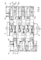
- Figure 2 is a plan view of the rolling mill of Figure 1,
- Figure 3 is a schematic view of the above-mentioned rolling mill, partially sectioned transversely,
- Figure 4 is a side view of the above-mentioned rolling mill,
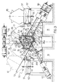
- Figure 5 is a schematic view of some details of Figure 3,
- Figures 6, 7 and 8 show a detail of the rolling mill of the preceding drawings, in respective operative conditions.
- With reference to these drawings, therefore, a rolling mill for processing pipes on a mandrel according to the invention is generally indicated at 1; it has an outer structure 2 which is disposed concentrically to a rolling axis L and is supported on a base B; the structure 2 is constituted by a plurality of plate-
like elements 3 which, as will be described further below, are connected rigidly to one another by means oftie rods 4 and are part of the respective outer structures of a plurality of rolling units 5 aligned along the longitudinal axis L between aninput end 6 and an output end 7 for the pipes being processed. Theseends 6 and 7 are at opposite ends of the structure 2, respectively. - As stated above, each rolling unit 5 according to the invention comprises a pair of plate-
like elements 3 disposed side by side and connected to one another by thetie rods 4 in the general structure 2; more particularly, in this embodiment, the plate-like elements 3 are in the form of substantially circular rings or, in any case, closed rings, on the outer edges of which there are someappendix 8 which will be considered further below, together with other structural details of the invention; in practice, therefore, two consecutive, rigidly interconnectedelements 3 in the rolling mill define an outer support structure of each rolling unit. In the rolling mill of this embodiment, all of the rolling units with the respective support structures are connected to one another without loss of continuity and the two faces of a single plate-like element 3 are therefore parts of respective adjacent units along the rolling axis L. - Each rolling unit 5 has a
respective roll carrier 10 in the form of a substantially triangular, or in any case closed, annular frame which is housed between two consecutive plate-like elements 3 in the rolling mill 1; for each rolling unit there are also removable means for locking the carrier in the working position adopted during the rolling of a pipe. - Three
pins roll carrier 10 at the vertices of an equilateral triangle inscribed in the cross-section of the carrier andrespective lever arms pins corresponding lever arms roll carrier 10 in a known adjustable manner for which reference should be made to the patent applications of the prior art already cited. - In the embodiment of the invention described herein the
arms lever arms -
Respective support elements arms pins corresponding rolls - In a preferred embodiment of the invention, the support elements are mounted on the ends of the arms in a frontally adjustable manner; an example of this adjustable mounting is described and claimed in ITALIAN PATENT No. IT-B-1254864 already cited, where it is achieved by means of bolts and slotted holes (see Figure 3 of this application) which are also applicable in this case; naturally, however, other solutions should not be excluded.
- For each
roll device rolls arms support elements - In this embodiment of the invention, the
adjustment devices like elements 3 in the region of theappendix 8 on the outer edges thereof, and amovable portion 30b, 31b or 32b which can slide back and forth relative to the aforesaid fixed portion along a radial axis passing through the rolling axis L and arranged at 120° to the other two homologous axes. - In fact it should be noted, with regard to the
adjustment device 31, that its fixedportion 31a is mounted rotatably on apin 31c fixed between two plate-like elements 3 of a rolling unit 5; thisadjustment device 31 is associated with anactuator 31d acting on thefixed portion 31a in order to rotate the latter about thepin 31c between an operative position in which the movable portion 31b is slidable along the radial axis extending through the rolling axis and arranged at 120° to the other two mentioned above, and an inoperative position in which theadjustment device 31 is retracted relative to a pair ofguides 15 arranged transverse the rolling axis. These guides extend parallel to one another and are fixed to respective plate-like elements 3 of a rolling unit; the direction of sliding of the movable portion 31b is thus defined when thefixed portion 31a is in the operative position. - The
movable portion 30b, 31b or 32b of each adjustment device acts on aspacer support element corresponding hole 33 passing through theroll carrier 10, throughout its thickness, and is situated at a respective vertex of the triangular shape of the carrier. Moreover, suitable biasing means 34 of known type, constituted by a lever mechanism operated by a small hydraulic cylinder, compensate for the weight of eachroll support arms - As will become clearer from the following description, the biasing means 34 associated with the
arm 20, that is, the arm on which theadjustment device 31 acts, can move from the arrangement in which it holds the roll in the rest position, in order to allow thecorresponding carrier 10 to come out. - The
roll carriers 10 are housed in the structure 2 of the rolling mill of the invention in a manner such that, as already stated, the sliding axes of themovable portions 30b, 31b and 32b of the adjustment devices associated with aroll carrier 10 are disposed at 120° to one another and are offset by 60° relative to the analogous axes of the movable portions of thedevices - The offset arrangement referred to above (which is visible in Figure 5) is linked with that of the axes A1, A2 and A3 of a corresponding set of three rolls which, except for their displacement during rolling due to the pivoting of the respective arm, are oriented at 60° to one another, like the sides of an equilateral triangle; this fact, together with the particular arrangement of the
sliding guides 15 of a carrier for each rolling unit, confers an advantageous symmetry on the rolling units with respect to a vertical axis V extending through the rolling axis (see Figure 5, where an angle of 30° is indicated α). - In the rolling mill 1 there is also a
mandrel 40 which is moveable along the rolling axis L and is driven by a mandrel-holder 41 shown schematically in Figure 1; in this embodiment, the rolling mill is of the type with a mandrel held by means of ashaped tang 40a provided for connection to the mandrel-holder 41. - As mentioned above, each rolling unit 5 of the rolling mill 1 has
linear guides 15 which extend transverse the rolling axis L and lie in a plane inclined at an angle α of 30° to a horizontal plane extending through the aforementioned rolling axis; moreover, theguides 15 of one unit extend from the opposite side of the rolling mill to those of the adjacent rolling unit. - As will become clearer from the following description, the direction in which the
guides 15 extend and, more generally, that in which aroll carrier 10 slides, are advantageously parallel to the axis of rotation A1, A2, or A3 of one of therolls - This latter fact, together with the arrangement of the rolls and of the respective adjustment devices just mentioned, enables the roll carriers of all of the rolling units to be identical to one another and the outer structure of each rolling unit with the guides mounted thereon, together with the carriers housed inside them, to be formed as those of an adjacent rolling unit in the rolling mill tilted about the vertical axis V extending through the axis L.
- Each
roll carrier 10 haswheels 48 to facilitate its running along theguides 15 and, beside each rolling unit, on the side on which theguides 15 extend, there is adevice 50 for loading-unloading roll carriers, associated with anextractor 45; the latter is constituted essentially by a thrust element acting parallel to theguides 15 and having an engagement end 45a which engages anappendix 46 of matching shape on the roll carrier. - The loading-
unloading device 50 of each rolling unit has acarriage 51 movable onrails 52 parallel to the rolling axis L; thecarriage 51 has twotiltable platforms oleodynamic lifters 54. On theplatforms linear guides corresponding platform guides 15 of the associated rolling unit. - A mandrel-
support apparatus 80 with which the rolling mill of the invention is provided will now be described with reference to Figures 6, 7 and 8; more precisely, the rolling mill has several of these devices disposed between two rolling units 5 of the rolling mill and close to theinput end 6 and to the output end 7 for the pipes being processed. - The
apparatus 80 comprises a substantially L-shaped body 81 which can swing transversely relative to the rolling mill and in which there is aseat 86 where three idle mandrel-support rolls system 85 causing them to move from an operative position in which they support a mandrel extending through the apparatus, to an inoperative position in which the rolls are moved away from the rolling axis so as not to interfere with a pipe during rolling. - The
apparatus 80 also includes astop element 87 for keeping theswinging body 81 in an operative position, that is, in a position in which theseat 86 is concentric with the axis L so that therolls body 81 is moved away from the rolling axis. It is hardly necessary to point out that the swinging movement of thebody 81 is brought about by means of ahydraulic actuator 88 but, naturally, could be achieved by any other suitable means. - Finally, it should be borne in mind that the
rolls independent motors 90 together withdrive extensions 91, the latter being connected mechanically to the former by couplings, not shown in detail in the drawings, which enable the extensions to be moved axially by means of the hydraulic actuators M, as will be explained further in connection with the operation of the invention which will be described below; before proceeding with this description, it is stated solely that, in the rolling mill of the invention, there are means for adjusting and controlling the various rolling stages, that are not described in detail and the functions of which can in any case be inferred from the explanation given below. - A pipe to be rolled is inserted from the
input end 6 of the rolling mill, fitted on themandrel 40; it is then advanced along the rolling axis by the rotation of the rolling rolls of each unit with which it comes into contact in succession. More particularly, the rolls of each rolling unit are held in predetermined positions by the combined effect of the biasing means 34 and of theadjustment device spacers corresponding support elements - When a pipe being rolled, fitted on the mandrel, encounters the rolls of a rolling unit, it therefore exerts a radial force which is transmitted by means of the
support elements adjustment devices like elements 3. - Since these
elements 3 have closed cross-sections, that is, cross-sections taken in a plane perpendicular to the rolling axis, the outer structure of each rolling unit formed thereby is best able to withstand the aforementioned rolling stresses, thus contributing to the achievement of the first part of the object set at the beginning. - With regard to the replacement of the rolls for the rolling units, this takes place as follows.
- The means for clamping a carrier in its working position which is occupied during rolling are released so that a
roll carrier 10 can slide along theguides 15 of the respective unit; at this stage, the biasing means 34 are also de-activated and those associated with thearm 20 in particular are translated so as not to interfere with the carrier to be removed. - Similarly, the
extensions 91 for driving the rolls are also disconnected therefrom and are retracted axially by the hydraulic actuators M so as to be moved out of the roll carrier. In this situation, theadjustment device 31 is placed in the retracted position relative to theguides 15 so as not to interfere with the movement of the carrier along them. - The
thrust element 45 is activated to move the roll carrier to be removed along theguides 15 until it is brought to their ends where theplatform 53 of thecarriage 51 associated with the rolling unit has in the meantime been tilted; the carrier is then placed on the tilted platform and, after it has been fully loaded thereon, thelifter 54 is lowered so as to bring the platform, with the roll carrier resting on it, to a horizontal position. - The
carriage 51 is then advanced so as to bring thesecond platform 53a, on which the new roll carrier to be inserted is disposed, to a position such that theguides 55a are in alignment with those of the roll unit; the new carrier is then inserted in the rolling unit in the place of that to be replaced by the repetition, in reverse, of the steps just described for the removal of the carrier to be replaced. - It can be understood from the foregoing that this method of carrying out the roll-changing operation achieves the other part of the object set at the beginning.
- In fact, this roll-changing operation now takes place at the side of the rolling mill and thus without requiring a large space downstream thereof as was, however, the case with axial sliding of the roll carriers envisaged in the prior art.
- Finally, this result is achieved by virtue of the provision of a passage in the outer structure, for each rolling unit, through which the carrier can come out, but without substantial alteration of the annular configuration of the outer structure.
- Many advantageous effects are achieved by the invention.
- Amongst these, it should be pointed out that, by virtue of the fact that the roll-changing is carried out alternately on one side of the rolling mill and on the other for each rolling unit contained therein, a replacement roll carrier for each unit can be provided at the side of the rolling mill, without interfering with the removal of another carrier from the structure.
- In fact, if the roll-changing operation were to take place from a single side of the rolling mill, it would not be possible to provide a replacement carrier beside each rolling unit; in other words, if roll-changing were carried out from only one side of the rolling mill, this operation would have to be carried out either by removing first all of the roll carriers from the rolling mill and subsequently moving them away from the mill in order then to be able to load the new replacement roll carriers, after they have been brought to a position beside the corresponding rolling units, or by removing one carrier individually and then inserting the replacement one, for each rolling unit. Both of these solutions are less favourable than that proposed by the invention.
- Another advantageous aspect to be emphasized with regard to the embodiment of the invention considered herein lies in the individual motorization of each roll of a rolling unit, that is, the use of an independent drive for each roll, by virtue of which it is possible to avoid the presence of complicated transmission mechanisms beside the rolling mill, thus creating the space necessary to allow the carriers to be removed and handled as described above.
- More generally, with regard to the driving of the
rolls - A further and considerable advantage achieved by the invention lies in the fact that the axial stresses which arise during rolling, that is, the stresses having resultants parallel to the rolling axis L and which, although smaller than the radial stresses considered above, may assume quite significant values, are absorbed by the outer structure of each rolling unit. In order better to understand this effect, it is necessary to consider that the axial stresses mentioned tend to displace the support elements of the rolls, and consequently also the respective roll carriers, in the direction of advancement of the pipe along the rolling axis L; as shown in Figure 4, the tendency of each
support element like elements 3 adjacent thecarrier 10 on which each roll is mounted. On this point, it should be stated that the tendency of each support element and of the roll carriers to move, as well as the restraining effect of the plate-like elements 3 on this movement, can take place both when thearms - It can easily be understood from the foregoing that, by virtue of the particular structural configuration and the effects achieved thereby, in the rolling mill of the invention, the axial stresses are distributed over all of the rolling units, unlike the rolling mill described in ITALIAN PATENT No. IT-B-1254864, wherein these stresses were withstood by suitable means provided at the end of the rolling mill; the rolling units of the invention and the rolling mill formed thereby thus enable the means provided in the prior art to be eliminated, simplifying the construction of the rolling mill.
- It should also be pointed out that, in the other prior art ITALIAN PATENT No. IT-B-1264032 considered, diaphragms 9 in the form of large plates were provided for withstanding the axial stresses and the displacement of the support elements mentioned above; this was implied by the "C"-shape, that is open-sided, structure which did not permit an effective action such as that which can, however, be achieved by the annular configuration of the structure of the present invention. The simplification achieved by the present invention is also clear in this case.
- Another advantage achieved by the present invention that should be stressed is connected with the inclination to a horizontal plane of the sliding axes of the carriers which, together with the particular configuration of the rolling units with their roll carriers, both derived from their rotation relative to the vertical axis according to the teaching already described, achieves the substantially symmetrical and compact construction of the rolling mill as a whole shown in the drawings; this construction also includes the parts of the rolling mill which are outside the structure 2 such as, for example, the
rails 52 and thecarriages 53, and themotors 90 with theextensions 91, and thus contributes significantly to the limitation of construction costs. - The advantageousness of the provision for the sliding axes of the carriers, and thus also the
guides 15, to be parallel to the axis A1, A2 or A3 of one of the rolls should also be noted; it can in fact be understood from an observation of the drawings that, with this solution, acarrier 10 can be removed from its opposite side to that on which one of the drive extensions is engaged, that is, a side where there are no obstructions to the sliding of the carrier and where a carriage can be disposed. Moreover, this inclination also clearly enables a carrier to be housed firmly in the respective structure owing to its own weight which tends to keep it therein, favouring its correct attitude during rolling. - In this context, the advantageous effects achieved by the mandrel-
support apparatus 80 described should also be pointed out. - This apparatus has the function of enabling the mandrel to move inside the rolling mill in the complete or partial absence of a pipe, for example, when a mandrel from which a rolled pipe has been removed is returning from the output end 7 to the
input end 6 of the rolling mill; in this situation, in fact, therolls apparatus 80 are arranged to keep the mandrel in a position concentric with the space defined by therolls support apparatus 80 provided in the rolling mill shown in the drawings, prevent the mandrel from knocking against the rolls of the rolling units during its movement in the absence of a pipe. - Mandrel-support apparatuses which perform this function already exist in rolling mills of the prior art; however, the particular feature of that shown in Figures 6, 7 and 8 is that it can be moved away from the rolling axis L even during rolling. This capability is particularly advantageous when conditions arise in which the advance of the pipe and of the mandrel is blocked in the rolling mill during the rolling of a pipe; in these eventualities, it is in fact necessary to gain access to the interior of the rolling mill to carry out the necessary maintenance. Since, in such circumstances, it would clearly not be possible to remove the roll carriers from the structure, given the presence of the pipe and of the mandrel among the rolls, it is necessary to be able to create sufficient space between one rolling unit and another disposed beside in the rolling mill to permit the intervention of an operator.
- As shown in Figures 6, 7 and 8, once the articulated
system 85 has moved therolls support apparatus 80 can be moved relative to the mandrel with the pipe fitted on it, which are clamped in the structure 2 of the rolling mill, thus providing a space which can be used for access by a maintenance operator. - It should in any case be pointed out that this mandrel-support apparatus could be formed in a manner other than that considered herein; that is, it is not strictly necessary for it to have a swinging body such as that described, but it will suffice for it to have a configuration such as to enable it to be removed transverse the rolling axis; in practice, it will therefore only be necessary that the seat of it where the rolls are disposed be open on an axis transverse the rolling axis L, along which the device can be moved towards or away from the rolling axis, naturally after the rolls have been spaced therefrom.
- Naturally, other variants of the invention as described hitherto are possible.
- For example, it should not be excluded that the configuration of the mill wherein the plate-
like elements 3 are connected rigidly to one another by the tie rods to form the structure of two adjacent units, could be replaced by a configuration of the rolling mill in which the various rolling units are spaced apart; in other words, the formation of the rolling mill with a plurality of units 5 disposed side by side along the rolling axis but with their outer structures separate from one another, naturally with the characteristics of each unit necessary to achieve the object for which they were designed remaining unchanged, should not be ruled out. - Furthermore, it is also pointed out that the
adjustment devices portion movable portion 30b, 31b, 32b would together form a helical kinematic pair; in this case, the alternate movement forth of the movable portion described above would also be accompanied by a rotary movement thereof which would not, however, alter its effects which were pointed out above. - Finally, the use of the invention for purposes other than those envisaged, for example, for rolling pipes without a mandrel, or bars, rods, or rod-shaped bodies in general should also not be excluded.
- These and other possible variants, however, fall within the scope of the teaching which is based on the invention as can be inferred from the description given thereof and from the following claims.
Claims (16)
- A unit for rolling pipes on a mandrel, of the type comprising a closed, substantially annular, outer structure (3, 4) arranged along a rolling axis (L), a roll carrier (10) housed in the structure, three driven rolls (27, 28, 29) mounted on respective pivoting lever arms (19, 20, 21) with their axes of rotation (A1, A2, A3) transverse the rolling axis (L), a device (30, 31, 32) mounted on the outer structure and associated with each roll (27, 28, 29) for regulating the distance of its axis of rotation (A1, A2, A3) from the rolling axis (L), characterized in that the roll carrier (10) is guided for sliding between an operative position wherein it is locked in the outer structure (3, 4) and an inoperative position wherein it is removed therefrom along a direction substantially transverse to the rolling axis (L), the outer structure (3, 4) being adapted to allow the carrier to pass along this transverse direction and means (15, 45) being provided in the rolling unit for bringing about the sliding.
- A rolling unit according to Claim 1, characterized in that the outer structure comprises at least two plate-like elements (3) substantially in the form of closed rings, connected rigidly to one another by means of a plurality of tie rods (4).
- A rolling unit according to Claim 1 or Claim 2, characterized in that the lever arms (19, 20, 21) on which the rolls (27, 28, 29) are mounted pivot in a plane perpendicular to the rolling axis.
- A rolling unit according to Claim 1 or Claim 2, characterized in that the lever arms (19, 20, 21) on which the rolls (27, 28, 29) are mounted pivot in respective radial planes perpendicular to the axis of rotation (A1, A2, A3) of the corresponding roll and passing through the rolling axis (L).
- A rolling unit according to any one of the preceding claims, characterized in that the sliding direction of the carrier is inclined to a substantially horizontal plane extending through the rolling axis (L).
- A rolling unit according to Claim 5, characterized in that the angle of inclination of the sliding direction is about 30°.
- A rolling unit according to any one of the preceding claims, characterized in that each roll (27, 28, 29) is driven independently of the other two.
- A rolling mill for rolling pipes on a mandrel, characterized in that it comprises a plurality of rolling units according to any one of Claims 1 to 7, arranged side by side along the rolling axis (L).
- A rolling mill according to Claim 8, characterized in that the outer structures (3, 4) of the rolling units (5) are connected rigidly to one another forming a single outer structure (2) of the rolling mill.
- A rolling mill according to either of Claims 8 and 9, characterized in that, in the inoperative position, the roll carrier (10) of each rolling unit (5) is arranged beside the unit, and the inoperative position of a roll carrier (10) of one unit is on the side of the rolling mill opposite to the inoperative position of a carrier of the adjacent rolling unit.
- A rolling mill according to Claim 10, characterized in that the sliding directions of the roll carriers (10) relating to inoperative positions thereof which are on the same side of the rolling mill, lie in respective planes inclined at about 30° to a substantially horizontal plane extending through the rolling axis (L).
- A rolling mill according to any one of Claims 7 to 10, characterized in that the rolling units (5) are identical to one another and each is rotated with respect to the one beside it in the rolling mill, about a vertical axis (V) crossing the rolling axis (L).
- A rolling mill according to Claim 11 or Claim 12, characterized in that the means (15, 45) for the guided sliding of a roll carrier (10) comprise, for each rolling unit (5), a thrust element (45) acting on the carrier along its sliding axis, and in that they comprise, for each rolling unit (5), a loading-unloading device (50) which includes a carriage (51) movable on rails (52) parallel to the rolling axis (L) and having at least one platform (53, 53a) which can be tilted from a horizontal position to an inclined position wherein it can receive a roll carrier (10) pushed onto it by the thrust element (45).
- A rolling mill according to any one of Claims 7 to 13, characterized in that it comprises at least one mandrel-support apparatus (80) having a body (81) with a seat (86) wherein a plurality of rolls (82, 83, 84) are journalled so as to be movable away from and towards the rolling axis (L) between a working position in which they can support a mandrel disposed along the rolling axis and a position in which they are moved away from this axis, the seat (86) being open in a direction substantially transverse the rolling axis so that the mandrel-support apparatus (80) can be removed from the rolling mill when its rolls are in the removed position.
- A rolling mill according to Claim 14, characterized in that the body (81) is substantially "L"-shaped and can swing about an axis parallel to the rolling axis.
- A rolling mill according to any one of Claims 7 to 15, characterized in that each roll (27, 28, 29) of a rolling unit is driven independently of the other two by means of at least one respective motor (90).
Applications Claiming Priority (3)
| Application Number | Priority Date | Filing Date | Title |
|---|---|---|---|
| IT95MI002492A IT1279085B1 (en) | 1995-11-29 | 1995-11-29 | UNIT FOR LAMINATION FOR SPINDLE TUBES |
| ITMI952492 | 1995-11-29 | ||
| PCT/EP1996/004387 WO1997019767A1 (en) | 1995-11-29 | 1996-10-10 | A unit for rolling pipes on a mandrel |
Publications (2)
| Publication Number | Publication Date |
|---|---|
| EP0868231A1 EP0868231A1 (en) | 1998-10-07 |
| EP0868231B1 true EP0868231B1 (en) | 2000-02-09 |
Family
ID=11372622
Family Applications (1)
| Application Number | Title | Priority Date | Filing Date |
|---|---|---|---|
| EP96934600A Expired - Lifetime EP0868231B1 (en) | 1995-11-29 | 1996-10-10 | A unit for rolling pipes on a mandrel |
Country Status (12)
| Country | Link |
|---|---|
| US (1) | US6041635A (en) |
| EP (1) | EP0868231B1 (en) |
| JP (1) | JP4332681B2 (en) |
| KR (1) | KR19990071727A (en) |
| CN (1) | CN1167522C (en) |
| AT (1) | ATE189628T1 (en) |
| AU (1) | AU7288996A (en) |
| CA (1) | CA2239024C (en) |
| DE (1) | DE69606658T2 (en) |
| IT (1) | IT1279085B1 (en) |
| PL (1) | PL326979A1 (en) |
| WO (1) | WO1997019767A1 (en) |
Families Citing this family (21)
| Publication number | Priority date | Publication date | Assignee | Title |
|---|---|---|---|---|
| US6945084B2 (en) * | 2000-03-28 | 2005-09-20 | Kocks Technik Gmbh & Co. Kg | Rolling mill for rolling or sizing metal pipes |
| DE10015285C2 (en) * | 2000-03-28 | 2003-11-27 | Kocks Technik | Rolling mill for rolling metallic pipes, bars or wires |
| ITMI20051480A1 (en) * | 2005-07-29 | 2007-01-30 | Danieli & C Ohg Sp A | MILL WITH CAGE WITH THREE ADJUSTABLE ROLLERS |
| CN100369731C (en) * | 2005-08-29 | 2008-02-20 | 江苏通达科思茂塑料管材有限公司 | Method for quick assembling/dissembling mouth core mould and template therefor |
| DE102006009173B4 (en) * | 2006-02-24 | 2015-02-05 | Kocks Technik Gmbh & Co. Kg | Method for determining the rolling force in a roll stand and roll stand |
| BRPI0621813A2 (en) * | 2006-06-12 | 2011-12-20 | Sms Demag Innse S P A | retained seamless pipe chuck rolling mill |
| DE102007013902A1 (en) * | 2007-03-20 | 2008-09-25 | Universität Dortmund | Device for profile bending |
| CN100463734C (en) * | 2007-08-31 | 2009-02-25 | 王国亮 | Core rod slaving mechanism of 3 - roll thermal precise mill |
| CN100589893C (en) * | 2007-12-20 | 2010-02-17 | 中冶京诚工程技术有限公司 | Trio mill |
| ITMI20080947A1 (en) * | 2008-05-22 | 2009-11-23 | Danieli Off Mecc | LAMINATION CAGE AND ITS LAMINATE FOR THE LONGITUDINAL LAMINATION OF ASTIFORM BODIES |
| IT1399629B1 (en) * | 2010-04-20 | 2013-04-26 | Sms Innse Spa | LAMINATE FOR EXTENDED ARTICLES. |
| CN102327899B (en) * | 2011-10-11 | 2013-09-25 | 太原重工股份有限公司 | Mandrel support device of mandrel pipe mill and mandrel pipe mill |
| CN102728616A (en) * | 2012-06-13 | 2012-10-17 | 张家港长力机械有限公司 | Y-shaped rolling mill with multi-roller system |
| ITMI20121708A1 (en) * | 2012-10-10 | 2014-04-11 | Danieli Off Mecc | LAMINATION CAGE WITH THREE WORKING ROLLERS |
| CN103071680B (en) * | 2013-02-06 | 2014-12-31 | 中冶赛迪工程技术股份有限公司 | Pipe jacking machine unit |
| ITMI20131860A1 (en) * | 2013-11-08 | 2015-05-09 | Danieli Off Mecc | THREE ROLLING LAMINATION CAGE WITH SIDE CHANGE COMPARED TO THE LAMINATION LINE |
| ITUB20155314A1 (en) | 2015-10-23 | 2017-04-23 | Danieli Off Mecc | MULTI-CHAMBER MILL FOR ASTIFORM BODIES INCLUDING THREE ROLLED CAGES |
| DE102018207908A1 (en) * | 2018-05-18 | 2019-11-21 | Sms Group Gmbh | Stretch reduction mill with improved diameter and wall thickness tolerance |
| KR20200042660A (en) * | 2018-10-16 | 2020-04-24 | 현대자동차주식회사 | Apparatus for controlling display of vehicle, system having the same and method thereof |
| RU2721339C1 (en) * | 2019-07-29 | 2020-05-19 | Открытое акционерное общество "Электростальский завод тяжелого машиностроения" | Multistand longitudinal rolling mill |
| CN114453425A (en) * | 2021-12-31 | 2022-05-10 | 太原重工股份有限公司 | Double-side roll-changing continuous pipe rolling mill device adopting top positioning |
Family Cites Families (9)
| Publication number | Priority date | Publication date | Assignee | Title |
|---|---|---|---|---|
| IT1086314B (en) * | 1977-09-19 | 1985-05-28 | Innocenti Santeustacchio Spa | SUPPORT CAGE AND SPINDLE GUIDE IN CONTINUOUS LAMINATE WITH HOLDED SPINDLE |
| DE2845051C2 (en) * | 1978-10-16 | 1983-04-07 | Kocks Technik Gmbh & Co, 4010 Hilden | Rolling mill with exchangeable stands |
| US4366694A (en) * | 1980-09-17 | 1983-01-04 | Morgan Construction Company | Compact rolling mill |
| IT1168096B (en) * | 1981-06-11 | 1987-05-20 | Innocenti Santeustacchio Spa | CONTINUOUS CROSS-CAGE ROLLING MACHINE FOR THE PRODUCTION OF PIPES WITHOUT WELDING |
| IT1151443B (en) * | 1982-06-03 | 1986-12-17 | Innocenti Santeustacchio Spa | EQUIPMENT FOR SUPPORTING THE STEM HOLDER OF A HOT AXIAL DRILLING MACHINE OF BILLETS, INGOTS AND SIMILAR |
| GB2129722B (en) * | 1982-10-15 | 1985-12-11 | Ishikawajima Harima Heavy Ind | Pipe-rolling mills |
| DE3345665C2 (en) * | 1983-12-14 | 1986-11-27 | Mannesmann AG, 4000 Düsseldorf | Device for holding the rolling rod and for guiding the rolling stock |
| IT1254864B (en) * | 1992-04-15 | 1995-10-11 | Filippo Cattaneo | CONTINUOUS ROLLING MACHINE FOR SEAMLESS-SPINDLE PIPES AND LAMINATION UNIT WITH THREE OR MORE COMMANDED AND ADJUSTABLE ROLLS |
| IT1271808B (en) * | 1994-12-28 | 1997-06-09 | Innocenti Eng Spa | LAMINATION UNIT FOR TUBULAR BODIES OR ASTIFORMS IN GENERAL |
-
1995
- 1995-11-29 IT IT95MI002492A patent/IT1279085B1/en active IP Right Grant
-
1996
- 1996-10-10 DE DE69606658T patent/DE69606658T2/en not_active Expired - Lifetime
- 1996-10-10 AT AT96934600T patent/ATE189628T1/en not_active IP Right Cessation
- 1996-10-10 WO PCT/EP1996/004387 patent/WO1997019767A1/en not_active Application Discontinuation
- 1996-10-10 CA CA002239024A patent/CA2239024C/en not_active Expired - Lifetime
- 1996-10-10 EP EP96934600A patent/EP0868231B1/en not_active Expired - Lifetime
- 1996-10-10 CN CNB961994606A patent/CN1167522C/en not_active Expired - Lifetime
- 1996-10-10 AU AU72889/96A patent/AU7288996A/en not_active Abandoned
- 1996-10-10 PL PL96326979A patent/PL326979A1/en unknown
- 1996-10-10 JP JP52009497A patent/JP4332681B2/en not_active Expired - Lifetime
- 1996-10-10 US US09/077,640 patent/US6041635A/en not_active Expired - Lifetime
- 1996-10-10 KR KR1019980704005A patent/KR19990071727A/en not_active Application Discontinuation
Also Published As
| Publication number | Publication date |
|---|---|
| DE69606658D1 (en) | 2000-03-16 |
| CN1207061A (en) | 1999-02-03 |
| CN1167522C (en) | 2004-09-22 |
| CA2239024A1 (en) | 1997-06-05 |
| JP2000515068A (en) | 2000-11-14 |
| WO1997019767A1 (en) | 1997-06-05 |
| ITMI952492A0 (en) | 1995-11-29 |
| CA2239024C (en) | 2005-08-09 |
| DE69606658T2 (en) | 2000-06-15 |
| ATE189628T1 (en) | 2000-02-15 |
| AU7288996A (en) | 1997-06-19 |
| PL326979A1 (en) | 1998-11-09 |
| ITMI952492A1 (en) | 1997-05-29 |
| EP0868231A1 (en) | 1998-10-07 |
| IT1279085B1 (en) | 1997-12-04 |
| US6041635A (en) | 2000-03-28 |
| KR19990071727A (en) | 1999-09-27 |
| JP4332681B2 (en) | 2009-09-16 |
Similar Documents
| Publication | Publication Date | Title |
|---|---|---|
| EP0868231B1 (en) | A unit for rolling pipes on a mandrel | |
| US6276182B1 (en) | Rolling stand, having three or more swinging and adjustable arms | |
| EP0593709B1 (en) | A rolling stand for generic rolling mills having three or more adjustable driven rolls | |
| US8616037B2 (en) | Re-turning plant for rollers of a roller mill | |
| JP5194325B2 (en) | A longitudinally stretchable multi-stand rolling mill for rod-shaped bodies, comprising a stand having four rolls, and a method for replacing the stand. | |
| US11207723B2 (en) | Straightening apparatus for metal products and method to replace at least one straightening roll of said apparatus | |
| US4038855A (en) | Stretch reducing mill | |
| MXPA98004252A (en) | Unit for the boring or rolling of tubes in a mand | |
| CN103781563B (en) | Driving roller more exchange device for the driver of milling equipment | |
| KR102551750B1 (en) | roller table device | |
| JP2963221B2 (en) | Horizontal rolling mill | |
| RU2360753C1 (en) | Device for blank target into labour roll mill stand | |
| SU325059A1 (en) | DEVICE FOR TRANSFER OF ROLLERS | |
| JPS59113910A (en) | Rolling mill | |
| EP2666559A2 (en) | Apparatus for turning steel products | |
| JPH0259020B2 (en) | ||
| JPH01258803A (en) | Rolling mill |
Legal Events
| Date | Code | Title | Description |
|---|---|---|---|
| PUAI | Public reference made under article 153(3) epc to a published international application that has entered the european phase |
Free format text: ORIGINAL CODE: 0009012 |
|
| 17P | Request for examination filed |
Effective date: 19980608 |
|
| AK | Designated contracting states |
Kind code of ref document: A1 Designated state(s): AT DE FR GB IT |
|
| GRAG | Despatch of communication of intention to grant |
Free format text: ORIGINAL CODE: EPIDOS AGRA |
|
| GRAG | Despatch of communication of intention to grant |
Free format text: ORIGINAL CODE: EPIDOS AGRA |
|
| 17Q | First examination report despatched |
Effective date: 19990521 |
|
| GRAG | Despatch of communication of intention to grant |
Free format text: ORIGINAL CODE: EPIDOS AGRA |
|
| GRAH | Despatch of communication of intention to grant a patent |
Free format text: ORIGINAL CODE: EPIDOS IGRA |
|
| GRAH | Despatch of communication of intention to grant a patent |
Free format text: ORIGINAL CODE: EPIDOS IGRA |
|
| GRAA | (expected) grant |
Free format text: ORIGINAL CODE: 0009210 |
|
| RAP1 | Party data changed (applicant data changed or rights of an application transferred) |
Owner name: DEMAG ITALIMPIANTI S.P.A. |
|
| AK | Designated contracting states |
Kind code of ref document: B1 Designated state(s): AT DE FR GB IT |
|
| REF | Corresponds to: |
Ref document number: 189628 Country of ref document: AT Date of ref document: 20000215 Kind code of ref document: T |
|
| REF | Corresponds to: |
Ref document number: 69606658 Country of ref document: DE Date of ref document: 20000316 |
|
| ITF | It: translation for a ep patent filed |
Owner name: JACOBACCI & PERANI S.P.A. |
|
| ET | Fr: translation filed | ||
| PG25 | Lapsed in a contracting state [announced via postgrant information from national office to epo] |
Ref country code: GB Free format text: LAPSE BECAUSE OF NON-PAYMENT OF DUE FEES Effective date: 20001010 Ref country code: AT Free format text: LAPSE BECAUSE OF NON-PAYMENT OF DUE FEES Effective date: 20001010 |
|
| PLBE | No opposition filed within time limit |
Free format text: ORIGINAL CODE: 0009261 |
|
| STAA | Information on the status of an ep patent application or granted ep patent |
Free format text: STATUS: NO OPPOSITION FILED WITHIN TIME LIMIT |
|
| 26N | No opposition filed | ||
| GBPC | Gb: european patent ceased through non-payment of renewal fee |
Effective date: 20001010 |
|
| REG | Reference to a national code |
Ref country code: FR Ref legal event code: PLFP Year of fee payment: 20 |
|
| PGFP | Annual fee paid to national office [announced via postgrant information from national office to epo] |
Ref country code: IT Payment date: 20151012 Year of fee payment: 20 |
|
| PGFP | Annual fee paid to national office [announced via postgrant information from national office to epo] |
Ref country code: FR Payment date: 20151102 Year of fee payment: 20 |
|
| PGFP | Annual fee paid to national office [announced via postgrant information from national office to epo] |
Ref country code: DE Payment date: 20151230 Year of fee payment: 20 |
|
| REG | Reference to a national code |
Ref country code: DE Ref legal event code: R071 Ref document number: 69606658 Country of ref document: DE |