EP0833237A2 - Apparatus and method for creating three-dimensional objects - Google Patents
Apparatus and method for creating three-dimensional objects Download PDFInfo
- Publication number
- EP0833237A2 EP0833237A2 EP97121092A EP97121092A EP0833237A2 EP 0833237 A2 EP0833237 A2 EP 0833237A2 EP 97121092 A EP97121092 A EP 97121092A EP 97121092 A EP97121092 A EP 97121092A EP 0833237 A2 EP0833237 A2 EP 0833237A2
- Authority
- EP
- European Patent Office
- Prior art keywords
- base member
- dispensing head
- dispensing
- layer
- predetermined
- Prior art date
- Legal status (The legal status is an assumption and is not a legal conclusion. Google has not performed a legal analysis and makes no representation as to the accuracy of the status listed.)
- Granted
Links
Images

Classifications
-
- G—PHYSICS
- G05—CONTROLLING; REGULATING
- G05B—CONTROL OR REGULATING SYSTEMS IN GENERAL; FUNCTIONAL ELEMENTS OF SUCH SYSTEMS; MONITORING OR TESTING ARRANGEMENTS FOR SUCH SYSTEMS OR ELEMENTS
- G05B19/00—Programme-control systems
- G05B19/02—Programme-control systems electric
- G05B19/18—Numerical control [NC], i.e. automatically operating machines, in particular machine tools, e.g. in a manufacturing environment, so as to execute positioning, movement or co-ordinated operations by means of programme data in numerical form
- G05B19/41—Numerical control [NC], i.e. automatically operating machines, in particular machine tools, e.g. in a manufacturing environment, so as to execute positioning, movement or co-ordinated operations by means of programme data in numerical form characterised by interpolation, e.g. the computation of intermediate points between programmed end points to define the path to be followed and the rate of travel along that path
-
- B—PERFORMING OPERATIONS; TRANSPORTING
- B22—CASTING; POWDER METALLURGY
- B22F—WORKING METALLIC POWDER; MANUFACTURE OF ARTICLES FROM METALLIC POWDER; MAKING METALLIC POWDER; APPARATUS OR DEVICES SPECIALLY ADAPTED FOR METALLIC POWDER
- B22F3/00—Manufacture of workpieces or articles from metallic powder characterised by the manner of compacting or sintering; Apparatus specially adapted therefor ; Presses and furnaces
- B22F3/115—Manufacture of workpieces or articles from metallic powder characterised by the manner of compacting or sintering; Apparatus specially adapted therefor ; Presses and furnaces by spraying molten metal, i.e. spray sintering, spray casting
-
- B—PERFORMING OPERATIONS; TRANSPORTING
- B29—WORKING OF PLASTICS; WORKING OF SUBSTANCES IN A PLASTIC STATE IN GENERAL
- B29C—SHAPING OR JOINING OF PLASTICS; SHAPING OF MATERIAL IN A PLASTIC STATE, NOT OTHERWISE PROVIDED FOR; AFTER-TREATMENT OF THE SHAPED PRODUCTS, e.g. REPAIRING
- B29C41/00—Shaping by coating a mould, core or other substrate, i.e. by depositing material and stripping-off the shaped article; Apparatus therefor
- B29C41/34—Component parts, details or accessories; Auxiliary operations
- B29C41/36—Feeding the material on to the mould, core or other substrate
-
- B—PERFORMING OPERATIONS; TRANSPORTING
- B29—WORKING OF PLASTICS; WORKING OF SUBSTANCES IN A PLASTIC STATE IN GENERAL
- B29C—SHAPING OR JOINING OF PLASTICS; SHAPING OF MATERIAL IN A PLASTIC STATE, NOT OTHERWISE PROVIDED FOR; AFTER-TREATMENT OF THE SHAPED PRODUCTS, e.g. REPAIRING
- B29C64/00—Additive manufacturing, i.e. manufacturing of three-dimensional [3D] objects by additive deposition, additive agglomeration or additive layering, e.g. by 3D printing, stereolithography or selective laser sintering
- B29C64/10—Processes of additive manufacturing
- B29C64/106—Processes of additive manufacturing using only liquids or viscous materials, e.g. depositing a continuous bead of viscous material
- B29C64/118—Processes of additive manufacturing using only liquids or viscous materials, e.g. depositing a continuous bead of viscous material using filamentary material being melted, e.g. fused deposition modelling [FDM]
-
- B—PERFORMING OPERATIONS; TRANSPORTING
- B29—WORKING OF PLASTICS; WORKING OF SUBSTANCES IN A PLASTIC STATE IN GENERAL
- B29C—SHAPING OR JOINING OF PLASTICS; SHAPING OF MATERIAL IN A PLASTIC STATE, NOT OTHERWISE PROVIDED FOR; AFTER-TREATMENT OF THE SHAPED PRODUCTS, e.g. REPAIRING
- B29C64/00—Additive manufacturing, i.e. manufacturing of three-dimensional [3D] objects by additive deposition, additive agglomeration or additive layering, e.g. by 3D printing, stereolithography or selective laser sintering
- B29C64/40—Structures for supporting 3D objects during manufacture and intended to be sacrificed after completion thereof
-
- B—PERFORMING OPERATIONS; TRANSPORTING
- B33—ADDITIVE MANUFACTURING TECHNOLOGY
- B33Y—ADDITIVE MANUFACTURING, i.e. MANUFACTURING OF THREE-DIMENSIONAL [3-D] OBJECTS BY ADDITIVE DEPOSITION, ADDITIVE AGGLOMERATION OR ADDITIVE LAYERING, e.g. BY 3-D PRINTING, STEREOLITHOGRAPHY OR SELECTIVE LASER SINTERING
- B33Y10/00—Processes of additive manufacturing
-
- B—PERFORMING OPERATIONS; TRANSPORTING
- B33—ADDITIVE MANUFACTURING TECHNOLOGY
- B33Y—ADDITIVE MANUFACTURING, i.e. MANUFACTURING OF THREE-DIMENSIONAL [3-D] OBJECTS BY ADDITIVE DEPOSITION, ADDITIVE AGGLOMERATION OR ADDITIVE LAYERING, e.g. BY 3-D PRINTING, STEREOLITHOGRAPHY OR SELECTIVE LASER SINTERING
- B33Y30/00—Apparatus for additive manufacturing; Details thereof or accessories therefor
-
- B—PERFORMING OPERATIONS; TRANSPORTING
- B33—ADDITIVE MANUFACTURING TECHNOLOGY
- B33Y—ADDITIVE MANUFACTURING, i.e. MANUFACTURING OF THREE-DIMENSIONAL [3-D] OBJECTS BY ADDITIVE DEPOSITION, ADDITIVE AGGLOMERATION OR ADDITIVE LAYERING, e.g. BY 3-D PRINTING, STEREOLITHOGRAPHY OR SELECTIVE LASER SINTERING
- B33Y40/00—Auxiliary operations or equipment, e.g. for material handling
-
- B—PERFORMING OPERATIONS; TRANSPORTING
- B33—ADDITIVE MANUFACTURING TECHNOLOGY
- B33Y—ADDITIVE MANUFACTURING, i.e. MANUFACTURING OF THREE-DIMENSIONAL [3-D] OBJECTS BY ADDITIVE DEPOSITION, ADDITIVE AGGLOMERATION OR ADDITIVE LAYERING, e.g. BY 3-D PRINTING, STEREOLITHOGRAPHY OR SELECTIVE LASER SINTERING
- B33Y50/00—Data acquisition or data processing for additive manufacturing
- B33Y50/02—Data acquisition or data processing for additive manufacturing for controlling or regulating additive manufacturing processes
-
- G—PHYSICS
- G05—CONTROLLING; REGULATING
- G05B—CONTROL OR REGULATING SYSTEMS IN GENERAL; FUNCTIONAL ELEMENTS OF SUCH SYSTEMS; MONITORING OR TESTING ARRANGEMENTS FOR SUCH SYSTEMS OR ELEMENTS
- G05B19/00—Programme-control systems
- G05B19/02—Programme-control systems electric
- G05B19/18—Numerical control [NC], i.e. automatically operating machines, in particular machine tools, e.g. in a manufacturing environment, so as to execute positioning, movement or co-ordinated operations by means of programme data in numerical form
- G05B19/4097—Numerical control [NC], i.e. automatically operating machines, in particular machine tools, e.g. in a manufacturing environment, so as to execute positioning, movement or co-ordinated operations by means of programme data in numerical form characterised by using design data to control NC machines, e.g. CAD/CAM
- G05B19/4099—Surface or curve machining, making 3D objects, e.g. desktop manufacturing
-
- B—PERFORMING OPERATIONS; TRANSPORTING
- B22—CASTING; POWDER METALLURGY
- B22F—WORKING METALLIC POWDER; MANUFACTURE OF ARTICLES FROM METALLIC POWDER; MAKING METALLIC POWDER; APPARATUS OR DEVICES SPECIALLY ADAPTED FOR METALLIC POWDER
- B22F2998/00—Supplementary information concerning processes or compositions relating to powder metallurgy
-
- G—PHYSICS
- G05—CONTROLLING; REGULATING
- G05B—CONTROL OR REGULATING SYSTEMS IN GENERAL; FUNCTIONAL ELEMENTS OF SUCH SYSTEMS; MONITORING OR TESTING ARRANGEMENTS FOR SUCH SYSTEMS OR ELEMENTS
- G05B2219/00—Program-control systems
- G05B2219/30—Nc systems
- G05B2219/45—Nc applications
- G05B2219/45238—Tape, fiber, glue, material dispensing in layers, beads, filling, sealing
-
- G—PHYSICS
- G05—CONTROLLING; REGULATING
- G05B—CONTROL OR REGULATING SYSTEMS IN GENERAL; FUNCTIONAL ELEMENTS OF SUCH SYSTEMS; MONITORING OR TESTING ARRANGEMENTS FOR SUCH SYSTEMS OR ELEMENTS
- G05B2219/00—Program-control systems
- G05B2219/30—Nc systems
- G05B2219/49—Nc machine tool, till multiple
- G05B2219/49015—Wire, strang laying, deposit fluid, welding, adhesive, hardening, solidification, fuse
-
- G—PHYSICS
- G05—CONTROLLING; REGULATING
- G05B—CONTROL OR REGULATING SYSTEMS IN GENERAL; FUNCTIONAL ELEMENTS OF SUCH SYSTEMS; MONITORING OR TESTING ARRANGEMENTS FOR SUCH SYSTEMS OR ELEMENTS
- G05B2219/00—Program-control systems
- G05B2219/30—Nc systems
- G05B2219/49—Nc machine tool, till multiple
- G05B2219/49241—2-5-D lace cutting, work in xy and increment in z, repeat
-
- Y—GENERAL TAGGING OF NEW TECHNOLOGICAL DEVELOPMENTS; GENERAL TAGGING OF CROSS-SECTIONAL TECHNOLOGIES SPANNING OVER SEVERAL SECTIONS OF THE IPC; TECHNICAL SUBJECTS COVERED BY FORMER USPC CROSS-REFERENCE ART COLLECTIONS [XRACs] AND DIGESTS
- Y02—TECHNOLOGIES OR APPLICATIONS FOR MITIGATION OR ADAPTATION AGAINST CLIMATE CHANGE
- Y02P—CLIMATE CHANGE MITIGATION TECHNOLOGIES IN THE PRODUCTION OR PROCESSING OF GOODS
- Y02P10/00—Technologies related to metal processing
- Y02P10/25—Process efficiency
-
- Y—GENERAL TAGGING OF NEW TECHNOLOGICAL DEVELOPMENTS; GENERAL TAGGING OF CROSS-SECTIONAL TECHNOLOGIES SPANNING OVER SEVERAL SECTIONS OF THE IPC; TECHNICAL SUBJECTS COVERED BY FORMER USPC CROSS-REFERENCE ART COLLECTIONS [XRACs] AND DIGESTS
- Y02—TECHNOLOGIES OR APPLICATIONS FOR MITIGATION OR ADAPTATION AGAINST CLIMATE CHANGE
- Y02P—CLIMATE CHANGE MITIGATION TECHNOLOGIES IN THE PRODUCTION OR PROCESSING OF GOODS
- Y02P90/00—Enabling technologies with a potential contribution to greenhouse gas [GHG] emissions mitigation
- Y02P90/02—Total factory control, e.g. smart factories, flexible manufacturing systems [FMS] or integrated manufacturing systems [IMS]
-
- Y—GENERAL TAGGING OF NEW TECHNOLOGICAL DEVELOPMENTS; GENERAL TAGGING OF CROSS-SECTIONAL TECHNOLOGIES SPANNING OVER SEVERAL SECTIONS OF THE IPC; TECHNICAL SUBJECTS COVERED BY FORMER USPC CROSS-REFERENCE ART COLLECTIONS [XRACs] AND DIGESTS
- Y10—TECHNICAL SUBJECTS COVERED BY FORMER USPC
- Y10T—TECHNICAL SUBJECTS COVERED BY FORMER US CLASSIFICATION
- Y10T156/00—Adhesive bonding and miscellaneous chemical manufacture
- Y10T156/10—Methods of surface bonding and/or assembly therefor
- Y10T156/1002—Methods of surface bonding and/or assembly therefor with permanent bending or reshaping or surface deformation of self sustaining lamina
- Y10T156/1036—Bending of one piece blank and joining edges to form article
- Y10T156/1038—Hollow cylinder article
-
- Y—GENERAL TAGGING OF NEW TECHNOLOGICAL DEVELOPMENTS; GENERAL TAGGING OF CROSS-SECTIONAL TECHNOLOGIES SPANNING OVER SEVERAL SECTIONS OF THE IPC; TECHNICAL SUBJECTS COVERED BY FORMER USPC CROSS-REFERENCE ART COLLECTIONS [XRACs] AND DIGESTS
- Y10—TECHNICAL SUBJECTS COVERED BY FORMER USPC
- Y10T—TECHNICAL SUBJECTS COVERED BY FORMER US CLASSIFICATION
- Y10T156/00—Adhesive bonding and miscellaneous chemical manufacture
- Y10T156/17—Surface bonding means and/or assemblymeans with work feeding or handling means
- Y10T156/1798—Surface bonding means and/or assemblymeans with work feeding or handling means with liquid adhesive or adhesive activator applying means
Definitions
- This invention relates to an apparatus and process for forming a three-dimensional object of predetermined design, and in particular to the making of a model or article by depositing multiple layers of a material in a fluid state onto a base.
- the material is selected and its temperature is controlled so that it solidifies substantially instantaneously upon extrusion or dispensing onto a base, with the build-up of the multiple layers forming the desired article.
- Methods and techniques for making three-dimensional articles of a predetermined size and shape are known.
- the desired part is intially drawn, either manually or automatically utilizing a computer-aided design (CAD) procedure, with the article being ultimately formed by removing material from a block workpiece to form the desired shape in a machine operation.
- the machining operation may also be automatic with the utilization of a computer-aided machining (CAM) process.
- CAM computer-aided machining
- This costly and time consuming process is repeated multiple times to perfect the final manufacturing of a part, model, or prototype. The designer's success is often dependent upon either the interpretation or the skill of the machinist making the prototype or model.
- This common practice of mechanically removing material to create three-dimensional objects involves significant machining skills and machining Lime.
- Chemical machining techniques available to form objects have depth limitations and are incapable of making complex shapes.
- Thermal molding by injection or other molding techniques requires expensive molds and a procedure better adapted economically for large runs where reproducibility is required. With respect to jewelry applications
- the Masters procedure requires the use of two injection heads to achieve the desired three-dimensional article, requires a seed at the point of origin about which the article is constructed, and thus does not lend itself to the formation of successive layers of material in a predetermined pattern as a relatively simple means for building-up an article, such as a model or prototype.
- the Masters system builds up the article from a central seed by applying material to predetermined coordinates. Such a process presents inherent difficulties in holding close tolerances in the 0.001 inch (0.0025 cm) range without accumulative error build-up.
- U.S. Patent No. 4,818,562 issued to Frank G. Arcella et al discloses a method for forming an article by directing a laser beam to a fusible powder which is melted by the beam and solidifies on its surface to form an object of desired shape. This process is also very expensive, and is further complicated by the required use of a gas which is directed through the powder to fluidize it. Impurities in the gas must ultimately be removed, and the gas must be recirculated or vented by the use of complex gas-handling apparatus.
- Devices also exist for the manual making of models or sample articles, such as jewelry, from wax by the use of a wax dispensing gun from which the wax is dispensed in a heated, molten state.
- a wax-modeling gun is manufactured by the MATT Company, 663 Fifth Avenue, New York, New York.
- glue guns such as that manufactured by Parker Manufacturing Company of Northboro, Massachusetts, are available for heating and dispensing adhesives in a fluid, molten state for gluing articles together.
- the Parker glue gun utilizes a glue stick which is heated within the gun and dispensed as a melted glue.
- This invention has as its primary objective the provision of a process and apparatus by means of which three-dimensional objects can be created at an office work station in a very time and cost effective manner. It is anticipated that the invention will be particularly useful in the making of single prototypes or models of products so that they may be quickly made and studied by designers. Products having complicated shapes may thus be evolved effectively and efficiently through immediate observation of design errors and repeated modeling.
- these basic objectives are realized by dispensing a material at a controlled rate from a dispensing head onto a substrate or base member in a predetermined pattern dictated by the shape of an article to be formed, with the material being dispensed in multiple layers which solidify and adhere to each other to build up the article.
- the process is controlled so that the material in the preceding layer, and in particular at least the material under the dispensing head, has solidified before additional material is applied on top of it to form a subsequent layer.
- the present invention provides an apparatus for making three-dimensional physical objects of a predetermined shape by sequentially depositing multiple layers of solidifying material on a base member in a desired pattern, comprising:
- material is applied in a fluid state in very thin layers which adhere to the preceding layers in a multiple laminate of exceptionally smooth surface quality.
- the dispensing head is controllably elevated along a "Z" axis so as to sequentially form layers of material as thin as 0.0001 inches (0.00025 cm) or as great as 0.125 inches (0.3 cm) in thickness.
- the thickness of each layer is controlled by regulating the gap between the dispensing head and the previously-formed layer.
- drive motors are provided to selectively move the base member and dispensing head relative to each other in a predetermined pattern along "X" and "Y" axes as material is being dispensed. Relative vertical movement along a "Z" axis may also be carried out during the formation of each layer, as well as at the completion of each layer to achieve desired layer shape and thickness. Such mechanical movements are preferably achieved through drive signals inputed to the drive motors for the base member and dispensing head from a computer/controller CAD/CAM system.
- the design of an article to be formed is initially created on a computer, with commercially available software being utilized to convert the three-dimensional shape into multiple layer data which is transmitted as drive signals through a computer-aided machine (CAM) controller to the aforesaid drive motors.
- CAM computer-aided machine
- Each layer can have its own distinctive shape as controlled by the program in the CAD system, and the layers may have different thicknesses.
- the article-forming material is preferably supplied to the dispensing head in the form of a flexible strand of solid material from a supply source, such as a reel.
- a rod of solid material may also be used as the material-supply medium on the dispensing head.
- the material is heated above its solidification temperature by a heater on the dispensing head and applied as a fluid.
- the dispensing head includes a flow passage connected to a discharge outlet in a nozzle from which the fluid material is dispensed.
- the nozzle may advantageously function as a "doctor blade" acting on the surface of each layer as it is formed to closely control the thickness of each layer.
- Various materials including waxes, thermoplastic resins, and metals may be used to form three-dimensional articles as described herein.
- the material is preferably one which will melt at a preselected temperature and rapidly solidify without shrink distortion upon adhering to the previous layer.
- a temperature controller responsive to temperature sensors on the dispensing head is used to closely control the temperature of the supply material to a level of about 1°C above its solidification temperature at the point of discharge. This ensures consistent flow and that the material will solidify substantially instantly upon cooling, after discharge, with resultant efficiency in the article-forming process as multiple layers are discharged, solidify, and build-up.
- a supplemental heater on the nozzle tip responsive to the temperature controller provides the close control of the temperature of the material as it is discharged, to ensure that it is in a fluid state slightly above its solidification temperature.
- the present invention also provides a process for making a three-dimensional article comprising:
- the present invention also provides an apparatus for making three-dimensional, physical objects of a predetermined shape by depositing solidifying material on a base member in a desired pattern comprising:
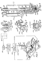
- Fig. 1 illustrates one embodiment of the apparatus of this invention for making three-dimensional articles, the apparatus being generally indicated by reference numeral 1.
- the apparatus includes a movable dispensing head 2 having a discharge nozzle 4 at its bottom end, dispensing head 2 being supported from a pedestal 6 by a mounting arm 8.
- Dispensing head 2 is located in close proximity to a base member comprising a plate 10 on which an article to be formed is built up as hereinafter set forth.
- Dispensing head 2 and base plate 10 are supported for mechanical movement relative to each other. In the preferred embodiment shown, this is accomplished by providing mechanical means for translational movement of base plate 10 laterally along "X" and "Y" axes of a base plane and for vertical movement of dispensing head 2 along a "Z" axis. Accordingly, as is shown in Figs. 1 and 2, base plate 10 is supported on an X-Y axis table 12 having a slide rod 14 in threaded engagement within its drive block 16 with a drive screw 18. A drive motor 20 provides rotary power to drive screw 18. Slide rod 14 also carries an elongated drive screw 22 driven by a second motor 24 and coupled to mating threads (not shown) secured to the underside of base plate 10 for driving engagement therewith. It will thus be seen that article-receiving base plate 10 may be moved along the X and Y axes indicated in Fig. 1 by the selected actuation of motors 24 and 20, respectively.
- Separate mechanical drive means are provided for up and down vertical movement of dispensing head 2.
- head 2 is mounted for vertical movement on a micro-slide bearing 26 on one end of support arm 8 by a bracket 28.
- One apertured end of right angle bracket 28 is threadedly engaged with a drive screw 30.
- a third drive motor 32 supplies driving, rotary power to screw 30 and is mounted on support arm 8 by bracket 34 as shown. Selected actuation of reversible motor 32 thus rotates screw 30 to provide up and down vertical movement of dispensing head 2 on slide bearing 26.
- motor 32 is preferably a high resolution stepper motor. It is to be noted, however, that various types of motors could be used for drive motors 20, 24, and 32, including stepper motors, linear motors, servo-motors, synchronous motors, D.C. motors, and fluid motors.
- motors 20, 24, and 32 are computer-controlled by drive signals generated from a computer 36, by means of which a computer-aided design (CAD) can be created at a design person's work station.
- CAD computer-aided design
- Support table 12 on which base plate 10 is carried is of such a size that it can be located on a desk top.
- a three-dimensional article can be designed and created at a single office work station by one operator, in the manner hereinafter set forth.
- the design of a three-dimensional article 40 is inputted to computer 36 utilizing commercially available CAD software.
- the article design is sectioned into multiple layers by a commercially available software program to provide multiple-layer data corresponding to the particular shape of each separate layer.
- software programs are in commercial use for computer-aided machining (CAM) purposes, and include NC Polaris, Smartcam, and Mastercam.
- AUTOLISP has been successfully used to layer AUTOCAD drawings into multiple layers or sections of specific patterns and dimensions.
- the layering data signals are directed to a machine controller 44 from the layering software 42 as shown diagramatically in Fig. 2. Controller 44 in turn is connected to the X, Y,and Z drive motors 24, 20, and 32, respectively, for selective acuation of those motors by the transmission of the layering drive signals.
- Various materials in different forms may be used for making three-dimensional articles with the apparatus described herein. It is preferred that the material be one which is thermally solidifiable from a fluid state in which it is applied, either at room temperature or at a predetermined temperature by the use of a cooling medium.
- Figs. 1 and 3 illustrate one embodiment in which the working material is supplied in the form of a solid rod 46, heated to its melting point in dispensing head 2 and dispensed from nozzle 4 as a flowable fluid.
- Suitable material include bees wax, casting wax, machineable and industrial waxes, parafin, a variety of thermoplastic resins, metals, and metal alloys.
- Suitable metals include silver, gold, platinum, nickel, alloys of those metals, aluminum, copper, gold, lead, magnesium, steel, titanium, pewter, manganese bronze. Glass, and particularly Corning glass, would also be satisfactory. Materials of varying degree of transparency would be useful in forming certain objects, such as for forming windows in model buildings. Chemical setting materials, including two-part epoxys would also be suitable.
- Materials which have been found to be particularly sutiabie for making three-dimensional objects with the apparatus disclosed herein include Freeman "machineable wax” manufactured by Freeman Manufacturing and Supply of Cleveland, Ohio, "Friendly Plastic” thermoplastic manufactured by Friendly Plastic of Boulder, Colorado, bismuth 153 alloy manufactured by Metal Specialties of Fairfield, Connecticut, and Thermoplastic Polymer No. 235-10, Specification No. 11061 sold by Ad-Tech of Hampton, New Hampshire.
- Supply rod 46 is inserted into supply chamber 50 of dispensing head 2 through a guide sleeve 48 as is best shown in Fig. 3.
- Various means may be utilized for advancing supply rod 46 through supply chamber 50 as material from the rod is dispensed through nozzle 4.
- One suitable means which has proven to be suitable for that purpose comprises a drive rod 52 which is attached as an extension to reciprocating piston 54 of a power cylinder 56.
- Cylinder 56 is a fluid cylinder which is preferably actuated by a supply of pressurized air through air line 58 from air compressor 60 and its receiver tank 62 in which a reservoir of compressed air is maintained.
- Air from the compressor/receiver 60/62 is delivered through supply line 58 and a 3-way solenoid valve 64 and a pressure-regulating valve 66 to air cylinder 56.
- a pressure gauge 68 is connected to the air pressure regulator 66, all as shown in Fig. 1.
- Drive rod 52 is connected by a pivotal link 70 to a ratchet head 72 having one or more ratchet teeth 74 which engage supply rod 46 to advance it downwardly within supply chamber 50 of dispensing head 2 towards dispensing nozzle 4.
- a predetermined air pressure preferably at a constant level, is maintained on top of piston 54 within cylinder 56 so as to move drive rod 52 downwardly.
- ratchet teeth 74 on ratchet head 72 will advance supply rod 46 downwardly within chamber 50.
- Drive rod 52 extends through an apertured bracket plate 78 within supply chamber 50, bracket plate 78 serving as a stop for a return spring 76 acting on the bottom of piston 54.
- Supply rod 46 is heated within heating head 84 to a predetermined temperature at which it will exceed its solidification temperature and melt to a flowable, fluid form.
- a main or primary cartridge type, electric resistance heater 80 is provided within heating head 84 within supply chamber 50 of dispensing head 2.
- a suitable seal ring 83 is provided around the top of heating head 84.
- An electrical power lead 82 is connected to resistance heater 80 as shown in Fig. 3.
- Heater 80 is closely controlled in order to heat the solid material of supply rod 46 to a temperature slightly above its melting point, and preferably on the order of 1°C above the melting point of the rod material.
- thermocouple-sensing element 88 is located as shown in close proximity to the supply rod 46 within heating head 84 so as to be able to sense the temperature to which the supply material is being heated.
- Temperature controller 86 has a main, adjustable controller as indicated in Fig. 1 which is set to a predetermined temperature to which the supply rod material is heated by resistance heater 80, in response to sensing signals received from thermocouple 88.
- a heater blade 92 forming a part of the heating assembly is embedded in the supply-rod material as shown in Fig. 3 and serves to directly heat it to the predetermined temperature.
- supply chamber 50 communicates with a flow passage indicated by reference numeral 94 and extending through discharge nozzle 4 to a dispensing outlet in the form of an orifice 98 of predetermined size at the bottom end of nozzle 4.
- a spring-loaded ball check valve 96 is located within flow passage 94, and opens to assist in metering the outlet flow of fluid material in response to the pressure maintained on the supply rod 46 within supply chamber 50.
- Check valve 94 also eliminates leakage from nozzle 4 when the system is stopped, even temporarily.
- Supply material from rod 46 reduced to a liquid state by heater 80 upstream of flow passage 94, flows downwardly into said flow passage and into dispensing outlet 98 from which it may be discharged onto base plate 10 to form layers of material in the course of building up an article.
- dispensing outlet 98 may be varied for the particular application, as by using interchangeable orifice inserts in the tip of nozzle 4. Also a variable size orifice of the type employed in cameras for varying the aperture could be utilized.
- Temperature controller 86 has a second, adjustable temperature regulator for the tip heater 100 as indicated in Fig. 1. That temperature regulator receives control signals from a second sensing device in the form off a thermocouple 102 attached to nozzle 4 in close proximity to flow passage 94 near its outlet end. As is also indicated in Fig. 1, the electrical connectors for thermocouples 88 and 102 both extend through power lead or conduit 90 connected to the temperature regulators for the main heater 80 and for tip heater 100 on temperature controller 86.
- ratchet head 72 As drive rod 52 moves downwardly towards the end of its rod supply stroke to bring ratchet head 72 near the position shown in Fig. 3, the piston 54 and drive rod 52 must be retracted upwardly in order that ratchet head 72 with its teeth 74 may take a new grip along supply rod 46 near its upper end.
- the upward and downward movement of drive rod 52 may be controlled by a limit switch within dispensing head supply chamber 50, which is activated by the downward movement of ratchet head 72 or pivotal link 70; or, alternatively, a timer 106 as shown schematically in Fig. 1 may be utilized to time the downward movement of supply rod 46 and to initiate the return of drive rod 52 at the expiration of a predetermined time interval.
- Either type of control device would be connected to air valve 64 so as to de-energize that solenoid valve and cut off the supply of pressurized air to the top of drive cylinder 56.
- return sping 76 urges piston rod 54 back upwardly. That movement is further assisted and permitted by the use of a quick release, vent valve 55 connected to the fitting on the top of air cylinder 56 as shown in Fig. 1.
- vent valve 55 connected to the fitting on the top of air cylinder 56 as shown in Fig. 1.
- Air valve 64 is then reopened at a timed interval by timer 106 to again introduce a supply of pressurized air on top of drive piston 54 within cylinder 56.
- the downward, supply movement of rod 46 is then reactivated.
- supply rod 46 moves downwardly within chamber 50, it is heated within heating head 84 to its melting point.
- liquid material flows downwardly into flow passage 94 and out through dispensing outlet 98.
- the opening and closing of air valve 64 to regulate the supply of pressurized air, and thus the supply of material in a fluid state through dispensing head 2 and its dispensing outlet 98 may also be accomplished by means of a relay 104 shown schematically in Figs. 1 and 2. As is indicated in Fig. 2, relay 104 is responsive to the software layering signals directed to the drive motor 32 which provides vertical movement of dispensing head 2 along a "Z" axis. Relay 104 may thus be energized and de-energized to open and close air valve 64 in response to programmed signals indicative of upward and downward movement of dispensing head 2.
- the metering of the material onto base plate 10 at a predetermined rate is accomplished by a combination of the preselected size of dispensing outlet orifice 98 as well as by the preselected, constant pressure maintained on piston 54 so as to control the rate at which supply rod 46 slowly advances through supply chamber 50 of dispensing head 2 as it is heated and reduced to a liquid state.
- the metered flow of material is also controlled by the gap or vertical height of the tip of nozzle 4 above the last layer and by the material viscosity.
- Various substrates may be utilized to receive an article being formed on top of base plate 10.
- Relatively fine, wire mesh sandpaper 108 as shown in Figs. 1 and 2 has been found to be particularly satisfactory for that purpose.
- the sandpaper substrate or foundation Day be readily peeled off of the bottom of the article without damage.
- the substrate or foundation 108 may advantageously take the form of a fine wire-mesh screen coated with sand and thus comprising an abrasive cloth, such as Norton No. 47650-4. such "sandpaper" or abrasive cloth can be applied to base plate 10 by double-faced adhesive tape.
- the substrate 108 is important in avoiding localized shrinkage in the foundation layer of the article being formed and in enhancing release of the article from base plate 110 without damage.
- the sand particles on the substrate 108 provide particularly effective adhesion of the dispensed material.
- the material also flows into and imbeds in the cells or pores of the open matrix wire screen. Separation of the article can be facilitated by using a conductive wire mesh screen substrate 108 made of copper wires to which a low voltage current is applied after the article is formed. This heats the screen slightly and frees the article.
- the wire mesh screen could be magnetized and iorn particles would be mixed into the supply material to enhance adhesion of the foundation layer to the substrate 108. Interruption of a magnetic field applied to base plate 10 would permit separation of the formed article.
- the substrate 108 could also be made of water-soluble wax, which could be dissolved to separate the article without damage.
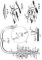
- Fig. 5 illustrates another version of the apparatus for dispensing supply material unto the movable base plate 10 in order to form a three-dimensional object by building up multiple layers.
- the supply material is in the form of a flexible strand in solid form.
- the flexible strand like the solid rod 46 of the embodiment of Fig. 3, is a solid material which can be heated relatively rapidly above its solidification temperature, and which will very quickly solidify upon a small drop in temperature after being dispensed onto the receiving plate 10. Any of the materials described above with respect to the embodiment of Figs. 1 and 3 would be satisfactory.
- a flexible strand of thermoplastic resin, wax, or metal in the form of a flexible wire, such as a strand of bismuth, gold or silver, would be suitable.
- the flexible strand 110 is advanced into and through a dispensing head 112 from a supply reel 114. It is fed through a guide sleeve 111 made of a suitable low friction material such as Teflon for support in motion.
- Dispensing head 112 has a supply chamber 118 with an inlet aperture 116 at its upper end, and a lower guide aperture 120 through which the flexible strand is fed towards discharge nozzle 122.
- Discharge nozzle 122 has a threaded connection as shown to dispensing head 112 and contains a central, material supply and flow passage 124 in flow communication at its lower end with a dispensing outlet orifice 126 of predetermined size to assist in providing a metered supply of material in a fluid state.
- a heater 128 in the form of a sleeve containing an electric resistance heater coil 130 is positioned around discharge nozzle 122 as shown closely adjacent to the walls of nozzle 122 for heating the supply strand in passage 124.
- a seal ring 132 is provided around the internal surface of flow passage 124 at the inlet to discharge nozzle 122 to provide an hydraulic seal at that location.
- a plurality of drive rollers 134 are provided within supply chamber 118 as shown, those rollers being drivingly connected to each other as by suitable belt or chain drives 143. Rotational power is supplied to the drive rollers by a motor 142 and a drive belt or chain 144. Motor 142 may take various forms. A high resolution stepper motor is preferred. A plurality of idler rollers 136 disposed opposite drive rollers 134 cooperate therewith to grip the flexible strand 110 therbetween and to advance it through dispensing head 112 towards the dispensing outlet 126 of nozzle 122. Rollers 136 are spring biased towards rollers 134 to maintain gripping, frictional contact on flexible strand 110 by the use of springs 140 acting on a pressure plate 138, which engages rollers 136.
- Supply reel 114 for the flexible strand may be free-wheeling, in which case drive motor 142 is the only driving, power source for advance flexible strand 110.
- motor 142 would preferably be a stepper motor.
- an additional drive motor 146 could be provided on rotary wheel 114, with motor 146 being a stepper motor to assist in controlling the advance of the flexible strand 110.
- two drive motors 142 and 146 being utilized, their speeds would be closely coordinated and controlled so that they advance flexible strand 110 at the same linear rate. With either drive arangement, sufficient slack is maintained in flexible strand 110 to permit unrestrained travel of dispensing head 112 as an article is being formed.
- Flexible strand 110 is preferably of a very small diameter, on the order of 1/16th inch (0.16 cm); however, fine flexible wires of supply material as small as 0.001 inch (0.0025 cm) in diameter may be utilized for controlled advancing through dispensing head 112.
- the rate of advance of flexible strand 110, and thus of the volumetric dispensing rate of the supply material onto base plate 10 can be very closely controlled.
- the flexible strand is heated to a predetermined temperature slightly above its solidification point by heater coil 130, within passage 124 of nozzle 122.
- the material is reduced to a fluid state in which it flows outwardly from dispensing outlet 126 onto the sandpaper-receiving surface 108 of base plate 10 as shown in Fig. 1.
- the material-supply apparatus of Fig. 5 would be utilized with the same X-Y table 12 and mechanically movable base plate 10 as shown and described with respect to Figs. 1 and 2.
- Dispensing head 112 like dispensing head 2, would be mounted on a support arm 8 for selective vertical movement along a "Z" axis by a control motor 32.
- a CAD design system utilizing computer 36 and related software for sectioning a design article into multiple layers as shown and described with respect to Figs. 1 and 2, would be utilized with the dispensing embodiment of Fig. 5.
- the supply material is heated to a fluid state in the dispensing head and metered at a controlled flow rate onto a receiving surface, such as sandpaper 108 positioned on base plate 10.
- a receiving surface such as sandpaper 108 positioned on base plate 10.
- the dispensing head 2 and base plate 10 are selectively moved with respect to each other in a predetermined pattern to form an article of desired shape.
- base plate 10 is movable along "X" and "Y" axes with the dispensing head being movable vertically along a "Z" axis.
- total, controlled movement to form the article could be achieved by moving either the base plate alone or the dispensing head alone, without moving the other.
- the supply material is dispensed in a fluid state from the dispensing head 2 or 112 through a dispensing outlet onto sandpaper 108 to form and build up multiple layers of material.
- Multiple passes of the dispensing head are made, with each pass taking place in a controlled pattern as dictated by the layering software 42 for multiple cross sections of the article being produced in accordance with design data inputted to computer 36.
- the computer and related software programs determine when the dispenser is on and off based on the original design drawing.
- the machine controller 44 controls the operation of drive motors 20, 24, and 32 along the "X,” “Y,” and “Z" axes. Each of these motors may be operating separately, or one or more of them may be operating simultaneously, depending upon the shape of the article to be formed.
- Circular patterns for each layer can be generated by controlled movement along the "X” and "Y” axes of the base plate 10.
- the dispensing head is initially positioned a predetermined height above base plate 10 or its receiving substrate 108 to form the first layer.
- the height of each subsequent layer is then closely controlled in order to dispense and form very thin layers. The thinner the layers, the smoother the resulting surface on the article. Layers as thin as 0.0001 inches (0.00025 cm) may be formed.
- the layers can be formed horizonally, vertically, or in any 360° oritentation to the horizontal. Depositing of the material may take place along only the "X” - "Y” plane, until it is advantageous to deposit in the "X" - "Z” plane or the "Z" - “Y” plane. Normally, the dispenser head will be mounted along the "Z" axis generally perpendicular to the "X" - "Y” plate of table 12.
- the initial relative movement of base plate 10 and the dispensing head will be in a horizontal plane along the "X" - "Y" axes.
- the first layer is dispensed and solidifies as it adheres to the substrate, such as sandpaper 108.
- the first layer may take any shape dictated by the computer program and it solidifies substantially instantly. No material is dispensed onto a previously formed layer, until that portion of the layer under the dispensing head has solidified.
- the second and each subsequent layer may take slightly different shapes, as dictated by the particular cross section for each layer from the computer program and layering software.
- motor 32 is selectively actuated after each layer is formed to raise the dispensing head incrementally along the "Z" axis a closely controlled, predetermined distance to control the gap between layers, and thus the thickness of each layer. After the dispensing head is thus raised, the next layer is dispensed and formed along a controlled path.
- the dispensing head may be moving in a direction along the "Z" axis as the layer is formed, such as when forming a spiral pattern, and the software program will control the location of the dispensing head at the end of each layer.
- the dispensing head when at the start position for the next layer, the dispensing head may have already been raised a distance along the "Z" axis above the corresponding point on the previously-formed layer. In such a situation, the dispensing head may not have to be elevated at all at the commencement of the next layer, or it may be elevated incrementally a very small distance to form the desired gap between layers, and thus the predetermined layer thickness.
- Each layer of material is dispensed in a liquid state, solidifies and adheres to the previous layer. This forms a very strong bond between layers.
- the bottom flat face of the nozzle provides a "doctor blade” effect as the nozzle and sandpaper substrate 108 are moved in an "X" - “Y” plane relative to each other.
- the dispenser tip limits the top of each layer to the precise "Z" axis setting, and thus assists in regulating the thickness of each layer so that no accumulated error along the "Z" axis occurs.
- the multiple layers may be off uniform thickness as shown in Fig. 4, or the layers may vary in thickness, as necessary and appropriate for the forming of a particular article. Also, the layers may each vary in thickness across the height of each layer, as shown in Fig. 9. As shown in the Fig. 9 illustration, the layers formed on the sandpaper substrate 108 may vary in height along inclined surfaces, and such surfaces may either be straight or arcuate.
- Feeding of the supply material is controlled relative to the "X" "Y,” and “Z" movement of the base plate 10 and dispensing head in such a way that the flow of material onto the substrate 108 is not starved or unduly excessive.
- the main concern is the control of layer thickness, and thus of smoothness of finish. If material spills over on one layer and/or is starved on other layers, the layers will be of irregular thickness with a resulting rough wall surface on the article produced.
- Supply material control may be accomplished in various ways.
- One approach utilizes the discharge of fluid material from the nozzle orifice by the advance of a solid rod 46 under a constant, predetermined air pressure as described and illustrated with respect to Figs. 1 and 3.
- the speed of motor 142 can be proportionally regulated in relation to the resultant "X,” “Y,” “Z” speed by sensing motors motors 20, 24, and 32.
- the volumetric flow rate of the supply material in a fluid state as discharged from dispensing head 112 would be controlled in a proportional relation to the "X” - “Y” speed of the dispensing head and base plate 10 relative to each other. This can be done by sensing the pulse signals driving motors 20 and 24, and sending proportional pulse drive signals to drive motor 142 on dispensing head 112.
- Effective on/off fluid dispensing can be achieved by simply stopping the advancing motors. This might be done, for example, when tracing a pattern which includes corners. To avoid puddling or excessive build-up of the supply material at the corners of a pattern, when there is no relative movement between the dispensing head and the base plate along the "X" - "Y" plane, the interruption of the drive signals to motors 20 and 24 can also be used to provide a stop signal to the drive motor(s) for advancing flexible strand 110.
- the "X" - "Y" drive motors 20 and 24 can be driven at a constant speed, without interruption. Such a speed would be selected to correspond to the slowest speed required to form patterns, such as around corners, where a relatively slow output feed of dispensing material would be required.
- the flexible strand 110 of Fig. 5 would be advanced at a constant linear rate by controlling the strand drive motors to correspond proportionally with such a constant speed movement of a dispensing head and base plate relative to each other in the "X" - "Y” plane. This approach to volume rate control of the supply material simplifies the control operation, but would necessitate a greater length off time for building up the article in desired layers.
- a flexible strand as the supply material in the dispensing head apparatus shown in Fig. 5 does permit close control of the dispensing of the supply material in a liquid state.
- the flexible strand 110 is of such a small diameter and of resulting small mass, that as it is heated in dispensing head 112, there is substantially minimal accumulation of supply material in a liquid state at the dispensing outlet 126.
- positive cut-off of the linear advancing movement of strand 110 substantially cuts off liquid material dispensing from the head 112.
- the flow of supply material may need to be interrupted in such a manner when moving the dispensing head vertically upwardly a predetermined distance along a "Z" axis after forming each layer, and prior to dispensing material in the next layer. Continued material flow from the dispensing head during such incremental vertical movement along the "Z" axis of the dispensing head could result in excessive accumulation of material on the preceding layer at a particular point.
- thermocouple 148 as shown in Fig. 5 may be located in close proximity to the internal passage 124 of nozzle 122, with thermocouple 148 being used in conjunction with a temperature controller 86 as described above with respect to Fig. 1, for the purpose of closely regulating the temperature of electric resistance heating element 130.
- the supply material utilized will have a solidification temperature permitting it to solidify substantially instantaneously at room temperature in which it is dispensed.
- a solidification temperature permitting it to solidify substantially instantaneously at room temperature in which it is dispensed.
- thermoplastic resin deposited in relatively thin layers less than 0.001 inch (0.0025 cm) in thickness solidifies substantially instantaneously upon being dispensed at room temperature.
- a cooling medium such as air, water, or freon may have to be utilized on or in conjunction with base plate plate 10 so as to cool the thermoplastic resin rapidly as it is dispensed in order to ensure that it will immediately solidify. Cooling medium application must be controlled. Over cooling can cause shrink distortion.
- cooling medium application for the purpose of rapidly solidifying the dispensed material will depend upon the nature of the material used.
- wax will cool and solidify substantially instantaneously in thin layers.
- compressed air supplied from compressor 60 and its receiving tank 162 was provided through a separate supply line 150, with its discharge end positioned closely adjacent the tip of discharge nozzle 4, as shown in Fig. 1.
- the cooling air from line 150 assisted in rapidly solidifying the wax as the multiple layers were formed.
- dispensing heads may be utilized for receiving and dispensing different types and/or different colors off dispensing material from separate sources.
- the dispensing head 112 may have multiple supply chambers 151 and 152 into which different supply materials 110a and 110b may be directed from separate supply sources.
- the supply materials 110a and 110b could be flexible strands supplied from a reel in the manner described and shown with respect to Fig. 5, or they could be in the form of rods as illustrated at 46 with respect to Fig. 1. In either case, different materials could be supplied and alternately melted by a resistance heater 156 on the dispensing head for flow through check valves 154 into alternate flow passages 124a and 124b.
- a resistance heater 156 on the dispensing head for flow through check valves 154 into alternate flow passages 124a and 124b.
- both of those passages communicate with a single discharge outlet or orifice 126 on the tip of nozzle 122.
- different materials such as thermoplastic resins and wax could be utilized to form different layers of the same article.
- the supply materials 110a and 110b could be provided in different colors in order to form alternate or different layers of different colors in the object being created.
- material 110a could be in the form of a red wax
- material 110b could be in the form of a blue plastic.
- a plurality of dispensing orifices 127 could also be arranged in a circular pattern on a dispensing head 112.
- the dispensing head would be of the same basic construction as shown in Fig. 6 with multiple supply passages 151, 152, etc., into which multiple rods or flexible strands of different compositions and colors of materials may be directed.
- the bottom of the dispensing head would terminate at section line 11-11 along which Fig. 11 is viewed.
- material would be dispensed through separate orifices 127 at the outlet off each check valve 154.
- Such a discharge head construction would expedite set-up time and also permit discharge of material from any desired number of orifices by selective control of the separate supply materials.
- thermally solidifying material could be dispensed into free space so as to be suspended above a base plate or substrate 108 to which it is bonded at selected locations.
- a dispensing head 112 would have an ultrasonic vibrator or horn 158 secured to its outlet end or dispensing tip as shown. Material would be supplied to the dispensing head 112 as a solid, and heated to a fluid or a liquid state by the use of a heating element such as that disclosed at 130 with respect to Fig. 5.
- Ultrasonic energy is then applied by means of the electrosonic vibrator 158, and the material is dispensed at a temperature slightly below its ambient solidification temperature, the energy supplied by ultrasonic vibration serving to increase the pressure and keep the material in a fluid state as it is discharged from dispensing outlet 126. Since the material is dispensed at a temperature below its solidification temperature, it will solidify instantaneously upon discharge.
- This technique can be utilized to form a pattern of material in threads, struts, or strands in free space, above substrate 108 as shown in Fig. 10. Each strand of material would be initially discharged onto the substrate for attachment to it.
- the dispensing tip with an ultrasonic vibrator can also be used to create three-dimensional objects without laminations.
- wire frame objects comprised of multiple, free-standing strands 180 defining wire frame segments anchored to a substrate 108 at spaced locations 180a and 180b could be formed as shown in Fig. 12.
- Each strand 180 instantaneously solidifies in space as it is dispensed from nozzle 112, with the nozzle and substrate being moved relative to each other in a predetermined pattern along "X,” "Y,” and “Z" axes by computer-driven control motors.
- the nozzle 112 could be canted to an angle from the vertical "Z" axis generally perpendicular to lines tangent to the arc being formed.
- a wire frame created CAD drawing can be directly translated into a wire frame, three-dimensional object.
- the strands are anchored at two points and also to each other where they refect.
- Cantilevered strands and objects can also be formed with each strand anchored at only one point on the substrate.
- Thin strands of material can be solidified as wire frames in free space to create hollow or open articles, including those of a spider web configuration or hollow, single piece spheres.
- the ultrasonic vibrator could alone be the means of fluidizing the material, with no heater being used.
- Instantaneous solidification of the material, even in free space, can also be accomplished by the use of a coolant such as Freon applied to the material as it is discharged from nozzle 112.
- the dispensing heads may be connected to outlet manifolds incorporating a plurality of dispensing outlets or orifices. Such a dispensing arrangement would be useful for forming a wide swath in multiple layers in a paint brush type of layering effect.
- Figs. 7 and 8 show a multiple orifice discharge manifold 162 which would be suitable for such purposes. Positioned along the length of the manifold 162 are a plurality off solenoid actuators, each having a connected plunger 166 with a bottom tip valve element 168 positioned in close, operating relation to a dispensing outlet or orifice 170.
- the controllers 164 could be electrically actuated solenoids, or they could be air actuators connected to a supply source of pressurized air, in a manner as is commonly utilized with air actuated valves.
- Material supply rods or strands 172 and 174 may be introduced lengthwise inside of manifold 164 as illustrated in Figs. 7 and 8.
- Main, electric resistance strip heaters disposed lengthwise along the internal wall surfaces of manifold 162 serve to initially heat and liquify the solid supply materials 172 and 174; and separate strip heaters 178 mounted on the outside surface of the bottom of the manifold adjacent to outlet 170 serve to closely control the temperature of the liquified material to a level just slightly above its solidification temperature. It will be appreciated that manifold 162 can be moved in a linear path across a receiving substrate so as to apply a wide swath of material for building up a relatively large object.
- feed rollers 134, 136 would be elongated along their rotational axes to grip and advance a plurality of flexible strands 110 supplied from a plurality of separate supply reels 114. Each strand would be advanced into a separate nozzle 122.
- the material could also be supplied to a dispensing head as a liquid from a liquid storage vessel using a fixed or variable displacement pump.
- a multiple part, chemically hardening, epoxy compound could be used as the article-forming material, with each of the epoxy components being supplied as a liquid from a separate supply source to a multiple-passage dispensing head.
Abstract
Description
whereby the first material dispensed from said dispensing head is received on and hardens to a solid on said open matrix substrate to thereby firmly anchor the article being formed.
Claims (21)
- Apparatus for making three-dimensional physical objects of a predetermined shape by sequentially depositing multiple layers of solidifying material on a base member in, a desired pattern, comprising:a movable dispensing head having flow-passage means therein connected to a dispensing outlet at one end thereof;a supply of material which solidifies at a predetermined temperature, and means for introducing said material in a fluid state into said flow-passage means;a base member disposed in working proximity to said dispensing outlet of said dispensing head; andmechanical means for moving said dispensing head and said base member relative to each other in three dimensions in a predetermined sequence and pattern with respect to said dispensing outlet; andmeans for metering the discharge of said material in a fluid state from said discharge outlet at a predetermined rate onto said base member so as to thus form a three-dimensional object.
- Apparatus as defined in claim 1 wherein:said means for introducing said material in a fluid state comprises heating means on said dispensing head controlled to heat said material to a temperature just above its solidification temperature, whereby said material flows from said dispensing outlet in a fluid state and solidifies substantially immediately upon discharge from said outlet at ambient temperature.
- Apparatus as defined in claim 1 wherein:said mechanical means for moving said dispensing head and said base member relative to each other comprises motor means mechanically connected to said dispensing head and operative to move said dispensing head vertically upwardly a predetermined incremental distance prior to the commencement of the formation of each successive layer so as to thereby control the gap between layers and to thus form multiple layers of said material of predetermined thickness which build up on each other sequentially as they solidify after discharge from said outlet, and whereby movement of said head-dispensing outlet in the course of forming each layer assists in controlling said gap.
- Apparatus as defined in claim 3 wherein:said base member is supported for translational movement along "X" and "Y" axes in a horizontal plane; andsaid mechanical means comprises second and third motor means operative to selectively move said base member along said "X" and "Y" axes.
- Apparatus as defined in claim 4, and further comprising:a computer-aided design computer programmed to create a three-dimensional drawing of a desired object or model, and software associated with said computer operative to convert the drawing into multiple elevation layer data; anda three-dimensional controller electronically linked to each of said motor means and operative to actuate each of said motors in response to "X," "Y," "Z" axis drive signals for each layer received from said computer.
- Apparatus as defined in claim 1 wherein:said material is a thermoplastic resin.
- Apparatus as defined in claim 1 wherein:said material is a wax.
- Apparatus as defined in claim 2 wherein:said supply of material is in solid form; andfurther including a material-advance mechanism operatively associated with said solid material to advance said material through said supply chamber towards said flow-passage means, said heating means serving to melt said solid material to a flowable, fluid state.
- Apparatus as defined in claim 8 wherein:said material is in the form of a continuous flexible strand; andfurther including material advance means operatively associated with said strand for the controlled advance of said strand of material through said supply chamber towards said flow passage means.
- Apparatus as defined in claim 9 and further including:a supply reel on which said flexible strand is wound, and said material-advance means comprises means for engaging said strand and pulling it from said reel.
- A process for making a three-dimensional article comprising:introducing a supply of thermally solidifiable material in a fluid state into a flow passage of a discharge nozzle on a mechanically moveable dispensing head, said nozzle having a dispensing outlet at one end thereof in fluid-flow communication with said flow passage;dispensing said material from said dispensing outlet at a predetermined temperature incrementally above the temperature at which it solidifies onto a base member positioned in close proximity to said nozzle;simultaneously with the dispensing of said material onto said base member, mechanically generating relative movement of said base member and said dispensing head with respect to each other in a predetermined pattern to form a first layer of said material on said base member; andelevating said dispensing head a predetermined height above said first layer, and after the portion of said first layer adjacent said nozzle has cooled and solidified, dispensing a second layer of said material in a fluid state onto said first layer from said dispensing outlet while simultaneously moving said base member and said dispensing head relative to each other, whereby said second layer solidifies upon cooling and adheres to said first layer to form a three-dimensional article.
- The process of claim 11 and further including:forming multiple layers of said material built up on top of each other in multiple passes by repeated dispensing of said material in a fluid state from said dispensing outlet as said base member and said dispensing head are moved relative to each other, with said dispensing head being elevated a predetermined height after each preceding layer is formed, and with the dispensing of each successive layer being controlled to take place after the material in the preceding layer immediately adjacent to said nozzle has solidified.
- The process of claim 12 and further including:introducing said material in a solid state into said dispensing head, and heating said material in said dispensing head to a temperature incrementally above its solidification temperature, whereby said material is directed into said flow passage in a fluid state.
- Apparatus for making three-dimensional, physical objects of a predetermined shape by depositing solidifying material on a base member in a desired pattern comprising:a dispensing head having means to hold a supply of material and to dispense such material in a fluid state;a base member disposed in working proximity to said dispensing head;an open matrix substrate on said base member;means for moving said dispensing head and said base member relative to each other in a predetermined sequence and pattern of movement simultaneously with the discharge of fluid material onto said substrate, whereby the first material dispensed from said dispensing head is received on and hardens to a solid on said open matrix substrate to thereby firmly anchor the article being formed.
- Apparatus as defined in claim 14 wherein:said substrate is a fine, wire mesh screen.
- Apparatus for making three-dimensional physical objects of a predetermined shape by sequentially depositing multiple layers of solidifying material on a base member in a desired pattern, comprising:a movable dispensing head (2) having flow-passage means (94) therein connected to a dispensing outlet at one end thereof, said outlet comprising a nozzle (4) configured in the form of a tip with a discharge orifice (98) of predetermined size therein to dispense material in a fluid state;a supply of material which solidifies and means for introducing said material in a fluid state into said flow-passage means (94);a base member (10) disposed in working proximity to said dispensing outlet of said dispensing head; andmechanical means for moving said dispensing head (2) and said base member (10) relative to each other in three dimensions along "X", "Y" and "Z" axes in a rectangular coordinate system in a predetermined sequence and pattern and for displacing said dispensing head a predetermined incremental distance relative to the base member and thence relative to each successive layer deposited prior to the commencement of the formation of each successive layer to form multiple layers of said material of predetermined thickness which build up on each other sequentially to form a three-dimensional object (40a) as said dispensing head and base member are moved relative to each other
characterised in thatthe apparatus further comprises means for metering the discharge of said material in a fluid stream from said discharge orifice at a predetermined rate onto said base member;the material is a thermally solidifiable material which solidifies at a predetermined temperature by cooling to a temperature below its solidification point;the material solidifies due to a lowering of temperature upon discharge from said orifice (98); andthe material is discharged from said orifice (98) at a predetermined temperature above the temperature at which it solidifies. - Apparatus according to claim 16, wherein said means for introducing said material in a fluid state comprises heating means (80) disposed in close proximity to said flow-passage means (94) controlled to maintain said material at a temperature above its predetermined solidification temperature in said flow-passage means (94) and at said orifice.
- Apparatus according to claim 17, wherein said material is in the form of a solid continuous flexible strand (110); and
the apparatus further includes material advance means operatively associated with said solid strand for the controlled advance of said solid strand of material towards said flow-passage means (94), said heating means (80) serving to melt said solid flexible strand to a flowable fluid state. - Apparatus according to any of claims 16 to 18, wherein the tip of the dispensing head has a bottom surface and, during the dispensing of a second layer of said material in a fluid stream onto said first layer from solid discharge orifice while generating relative movement between said base member and said dispensing head in the plane of said base member, said bottom surface of said tip is maintained substantially parallel to and in contact with said second layer, whereby said tip bottom surface provides a shearing effect on the top surface of said second layer of material as it is dispensed to thus closely control the absolute location of successive layers with respect to the base member and to avoid any accumulative error in layer build-up.
- A process for making a three-dimensional article (10) comprising:dispensing a solidifiable material in a fluid stream from a dispensing head having a tip with a discharge orifice therein;maintaining a predetermined gap distance between said bottom surface of said tip and a base member positioned in close proximity thereto, with said material being dispensed onto said base member;simultaneously with the dispensing of said material onto said base member, generating relative movement between said base member and said dispensing head in the plane of said base member to form a first layer of said material on said base member; andelevating said dispensing head a predetermined height above said first layer, and after the portion of said first layer adjacent said nozzle has solidified, dispensing a second layer of said material in a fluid stream onto said first layer from said discharge orifice while generating relative movement between said base member and said dispensing head in the plane of said base member
characterised in thatthe discharge of said material is metered in a fluid stream from said discharge orifice at a predetermined rate onto said base member;the material is thermally solidifiable material which solidifies at a predetermined temperature by cooling to a temperature below its solidification point;the process further includes immediately cooling the dispensed material to a temperature below its solidification temperature, whereby the dispensed material solidifies by cooling upon dispensing from said discharge orifice; andthe material is discharged from said orifice (98) at a predetermined temperature above the temperature at which it solidifies. - A process for making a three-dimensional article using the apparatus according to any of claims 1 to 10 or 14 to 19.
Applications Claiming Priority (3)
| Application Number | Priority Date | Filing Date | Title |
|---|---|---|---|
| US07/429,012 US5121329A (en) | 1989-10-30 | 1989-10-30 | Apparatus and method for creating three-dimensional objects |
| US429012 | 1989-10-30 | ||
| EP19900311640 EP0426363A3 (en) | 1989-10-30 | 1990-10-24 | Apparatus and method for creating three-dimensional objects |
Related Parent Applications (1)
| Application Number | Title | Priority Date | Filing Date |
|---|---|---|---|
| EP19900311640 Division EP0426363A3 (en) | 1989-10-30 | 1990-10-24 | Apparatus and method for creating three-dimensional objects |
Publications (3)
| Publication Number | Publication Date |
|---|---|
| EP0833237A2 true EP0833237A2 (en) | 1998-04-01 |
| EP0833237A3 EP0833237A3 (en) | 1998-04-22 |
| EP0833237B1 EP0833237B1 (en) | 2001-09-19 |
Family
ID=23701397
Family Applications (2)
| Application Number | Title | Priority Date | Filing Date |
|---|---|---|---|
| EP19900311640 Ceased EP0426363A3 (en) | 1989-10-30 | 1990-10-24 | Apparatus and method for creating three-dimensional objects |
| EP97121092A Expired - Lifetime EP0833237B1 (en) | 1989-10-30 | 1990-10-24 | Apparatus and method for creating three-dimensional objects |
Family Applications Before (1)
| Application Number | Title | Priority Date | Filing Date |
|---|---|---|---|
| EP19900311640 Ceased EP0426363A3 (en) | 1989-10-30 | 1990-10-24 | Apparatus and method for creating three-dimensional objects |
Country Status (6)
| Country | Link |
|---|---|
| US (2) | US5121329A (en) |
| EP (2) | EP0426363A3 (en) |
| JP (1) | JPH082598B2 (en) |
| AT (1) | ATE205944T1 (en) |
| CA (1) | CA2027731C (en) |
| DE (1) | DE69033809T2 (en) |
Cited By (26)
| Publication number | Priority date | Publication date | Assignee | Title |
|---|---|---|---|---|
| WO2001089714A1 (en) | 2000-05-19 | 2001-11-29 | Nederlandse Organisatie Voor Toegepast-Natuurwetenschappelijk Onderzoek Tno | Dispensing head and method for dispensing solidifying material |
| EP1184156A1 (en) * | 2000-09-01 | 2002-03-06 | Optoform Sarl Procedes de Prototypage Rapide | Photopolymerizable foam composition, rapid prototyping process and apparatus for making three dimensional articles, articles obtained therewith and their use |
| FR2817493A1 (en) * | 2000-12-04 | 2002-06-07 | Hugues Goulesque | DEVICE FOR MANUFACTURING THREE-DIMENSIONAL PARTS |
| EP1431852A2 (en) * | 2002-12-19 | 2004-06-23 | Fanuc Ltd | Synchronous controller |
| WO2009030791A1 (en) * | 2007-09-04 | 2009-03-12 | Fundació Privada Ascamm | Device and apparatus for selectively depositing molten plastic material and production method comprising selective deposition |
| WO2012040150A1 (en) * | 2010-09-22 | 2012-03-29 | Stratasys, Inc. | Liquefier assembly for use in extrusion-based additive manufacturing systems |
| CN103212689A (en) * | 2013-04-22 | 2013-07-24 | 中国科学院力学研究所 | Method of metal element moving tiny die-cast formation |
| CN103395208A (en) * | 2013-08-07 | 2013-11-20 | 苏州江南嘉捷机电技术研究院有限公司 | Synchronous fuse feeding three-dimensional printer |
| CN103691951A (en) * | 2013-12-20 | 2014-04-02 | 西北工业大学 | Three-dimensional printing forming device and method based on metal microdroplet track direction control |
| CN104209489A (en) * | 2014-08-26 | 2014-12-17 | 中国科学院力学研究所 | Device for implementing moving and micro die-casting molding of metal component |
| CN104226955A (en) * | 2014-08-26 | 2014-12-24 | 中国科学院力学研究所 | Precision casting furnace for realizing movable die-casting formation of metal component |
| CN104401002A (en) * | 2014-05-31 | 2015-03-11 | 福州大学 | 3D printing-based curved microlens array manufacturing method |
| CN104589466A (en) * | 2015-02-12 | 2015-05-06 | 王思涵 | Mechanical clay molding method and device |
| US9050753B2 (en) | 2012-03-16 | 2015-06-09 | Stratasys, Inc. | Liquefier assembly having inlet liner for use in additive manufacturing system |
| WO2016124432A1 (en) | 2015-02-03 | 2016-08-11 | Philips Lighting Holding B.V. | Fused deposition modeling based mold for molding and replicating objects, method for its manufacture and fused deposition modeling 3d printer |
| WO2016177627A1 (en) | 2015-05-07 | 2016-11-10 | Philips Lighting Holding B.V. | Materials that modify the interface properties of printed materials for obtaining objects with improved strength |
| WO2016193119A1 (en) | 2015-05-29 | 2016-12-08 | Philips Lighting Holding B.V. | 3d printing device and method |
| US9550319B2 (en) | 2014-02-07 | 2017-01-24 | The Boeing Company | Extrusion apparatus and method |
| WO2018153467A1 (en) | 2017-02-23 | 2018-08-30 | Wacker Chemie Ag | Generative method for producing molded bodies using a support material made of wax |
| CN109482887A (en) * | 2019-01-23 | 2019-03-19 | 北京工业大学 | A kind of metal paste extruded type metal 3D printer |
| DE102015221853B4 (en) | 2015-11-06 | 2019-05-16 | Technische Universität Bergakademie Freiberg | Process for the preparation of carbonaceous ceramic components |
| US10816149B2 (en) | 2015-12-29 | 2020-10-27 | Signify Holding B.V. | Customizable 3D-printed lighting device |
| EP3808309A1 (en) | 2016-07-15 | 2021-04-21 | Cudeti Sagl | Method for designing an implant |
| WO2022216631A1 (en) * | 2021-04-07 | 2022-10-13 | Us Synthetic Corporation | Nozzles including polycrystalline diamond or polycrystalline cubic boron nitride and related assemblies and methods |
| US11504926B2 (en) | 2015-12-22 | 2022-11-22 | Signify Holding B.V. | Use of semi-crystalline polymer with low Tg and post-crystallization for easy 3D printing and temperature stable products |
| US11633307B2 (en) | 2019-01-29 | 2023-04-25 | L'oreal | Porous formulation storage cushion, formulation delivery system, and method of manufacturing a porous formulation storage cushion |
Families Citing this family (984)
| Publication number | Priority date | Publication date | Assignee | Title |
|---|---|---|---|---|
| US5776409A (en) * | 1988-04-18 | 1998-07-07 | 3D Systems, Inc. | Thermal stereolithograp using slice techniques |
| US5141680A (en) * | 1988-04-18 | 1992-08-25 | 3D Systems, Inc. | Thermal stereolighography |
| US5216616A (en) * | 1989-06-26 | 1993-06-01 | Masters William E | System and method for computer automated manufacture with reduced object shape distortion |
| US5134569A (en) * | 1989-06-26 | 1992-07-28 | Masters William E | System and method for computer automated manufacturing using fluent material |
| US5121329A (en) * | 1989-10-30 | 1992-06-09 | Stratasys, Inc. | Apparatus and method for creating three-dimensional objects |
| US5204055A (en) * | 1989-12-08 | 1993-04-20 | Massachusetts Institute Of Technology | Three-dimensional printing techniques |
| US5387380A (en) * | 1989-12-08 | 1995-02-07 | Massachusetts Institute Of Technology | Three-dimensional printing techniques |
| IT1247585B (en) * | 1990-02-22 | 1994-12-28 | Jobs Spa | THREE-DIMENSIONAL MULTI-FUNCTION PLOTTER |
| US5257657A (en) * | 1990-07-11 | 1993-11-02 | Incre, Inc. | Method for producing a free-form solid-phase object from a material in the liquid phase |
| US5569349A (en) * | 1990-10-04 | 1996-10-29 | 3D Systems, Inc. | Thermal stereolithography |
| JP2597778B2 (en) * | 1991-01-03 | 1997-04-09 | ストラタシイス,インコーポレイテッド | Three-dimensional object assembling system and assembling method |
| US5740051A (en) * | 1991-01-25 | 1998-04-14 | Sanders Prototypes, Inc. | 3-D model making |
| US5204823A (en) * | 1991-03-20 | 1993-04-20 | Calcomp Inc. | Method and apparatus for high-speed layer thickness curing in 3-D model making |
| US5319568A (en) * | 1991-07-30 | 1994-06-07 | Jesco Products Co., Inc. | Material dispensing system |
| EP0535984B1 (en) * | 1991-10-02 | 1998-08-19 | Spectra Group Limited Inc | Production of three-dimensional objects |
| US5677107A (en) * | 1991-10-02 | 1997-10-14 | Spectra Group Limited, Inc. | Production of three-dimensional objects |
| US5510066A (en) * | 1992-08-14 | 1996-04-23 | Guild Associates, Inc. | Method for free-formation of a free-standing, three-dimensional body |
| KR940006732A (en) * | 1992-09-04 | 1994-04-25 | 히로시 우찌다 | Simultaneous supply of particles, simultaneous supply and suction removal of particles, and a method of manufacturing a molded article using these devices |
| US5490882A (en) * | 1992-11-30 | 1996-02-13 | Massachusetts Institute Of Technology | Process for removing loose powder particles from interior passages of a body |
| US5775402A (en) * | 1995-10-31 | 1998-07-07 | Massachusetts Institute Of Technology | Enhancement of thermal properties of tooling made by solid free form fabrication techniques |
| US5814161A (en) * | 1992-11-30 | 1998-09-29 | Massachusetts Institute Of Technology | Ceramic mold finishing techniques for removing powder |
| JP2558431B2 (en) * | 1993-01-15 | 1996-11-27 | ストラタシイス,インコーポレイテッド | Method for operating system for manufacturing three-dimensional structure and apparatus for manufacturing three-dimensional structure |
| US6146567A (en) * | 1993-02-18 | 2000-11-14 | Massachusetts Institute Of Technology | Three dimensional printing methods |
| DE4319128C1 (en) * | 1993-06-09 | 1995-02-23 | Fraunhofer Ges Forschung | Method and device for the free-forming production of three-dimensional components of a predetermined shape |
| US5398193B1 (en) * | 1993-08-20 | 1997-09-16 | Alfredo O Deangelis | Method of three-dimensional rapid prototyping through controlled layerwise deposition/extraction and apparatus therefor |
| US5583973A (en) * | 1993-09-17 | 1996-12-10 | Trustees Of Boston University | Molecular modeling method and system |
| US5976339A (en) * | 1993-10-01 | 1999-11-02 | Andre, Sr.; Larry Edward | Method of incremental layered object fabrication |
| US20070228110A1 (en) * | 1993-11-16 | 2007-10-04 | Formfactor, Inc. | Method Of Wirebonding That Utilizes A Gas Flow Within A Capillary From Which A Wire Is Played Out |
| US5879489A (en) | 1993-11-24 | 1999-03-09 | Burns; Marshall | Method and apparatus for automatic fabrication of three-dimensional objects |
| US5514232A (en) * | 1993-11-24 | 1996-05-07 | Burns; Marshall | Method and apparatus for automatic fabrication of three-dimensional objects |
| JP3152326B2 (en) * | 1993-12-24 | 2001-04-03 | 株式会社ケーネットシステムズ | Additive manufacturing method and additive manufacturing apparatus |
| JPH07227898A (en) * | 1994-02-04 | 1995-08-29 | Internatl Business Mach Corp <Ibm> | Part manufacturing method including bridging technique |
| JPH07227895A (en) * | 1994-02-04 | 1995-08-29 | Internatl Business Mach Corp <Ibm> | Part manufacturing method |
| US5503785A (en) * | 1994-06-02 | 1996-04-02 | Stratasys, Inc. | Process of support removal for fused deposition modeling |
| US5906863A (en) * | 1994-08-08 | 1999-05-25 | Lombardi; John | Methods for the preparation of reinforced three-dimensional bodies |
| US5537326A (en) * | 1994-09-12 | 1996-07-16 | Fish; Randall C. | System for manufacturing parts for a functional device such as a cyclone |
| US5555176A (en) * | 1994-10-19 | 1996-09-10 | Bpm Technology, Inc. | Apparatus and method for making three-dimensional articles using bursts of droplets |
| US5572431A (en) * | 1994-10-19 | 1996-11-05 | Bpm Technology, Inc. | Apparatus and method for thermal normalization in three-dimensional article manufacturing |
| US5859775A (en) * | 1994-10-19 | 1999-01-12 | Bpm Technology, Inc. | Apparatus and method including deviation sensing and recovery features for making three-dimensional articles |
| US5717599A (en) * | 1994-10-19 | 1998-02-10 | Bpm Technology, Inc. | Apparatus and method for dispensing build material to make a three-dimensional article |
| US5633021A (en) * | 1994-10-19 | 1997-05-27 | Bpm Technology, Inc. | Apparatus for making a three-dimensional article |
| WO1996013372A2 (en) * | 1994-10-19 | 1996-05-09 | Bpm Technology, Inc. | Build material for forming a three dimensional article |
| US5622216A (en) * | 1994-11-22 | 1997-04-22 | Brown; Stuart B. | Method and apparatus for metal solid freeform fabrication utilizing partially solidified metal slurry |
| DE4442961C2 (en) * | 1994-12-02 | 1998-07-02 | Fraunhofer Ges Forschung | Process for the production of components by electrochemical deposition |
| US5590454A (en) * | 1994-12-21 | 1997-01-07 | Richardson; Kendrick E. | Method and apparatus for producing parts by layered subtractive machine tool techniques |
| US5598200A (en) * | 1995-01-26 | 1997-01-28 | Gore; David W. | Method and apparatus for producing a discrete droplet of high temperature liquid |
| US5694324A (en) * | 1995-03-06 | 1997-12-02 | Masters; William E. | System and method for manufacturing articles using fluent material droplets |
| DE19511772C2 (en) * | 1995-03-30 | 1997-09-04 | Eos Electro Optical Syst | Device and method for producing a three-dimensional object |
| DE19515165C2 (en) * | 1995-04-25 | 1997-03-06 | Eos Electro Optical Syst | Device for producing an object using stereolithography |
| GB9510046D0 (en) * | 1995-05-18 | 1995-07-12 | Ecole Polytechnique Fudurale D | Process for the manufacture of polymer and composite materials and related equipment |
| US5622759A (en) * | 1995-06-23 | 1997-04-22 | Fuster; Marco A. | Skateboard grip tape |
| CN1064581C (en) * | 1995-07-04 | 2001-04-18 | 斯特拉特西斯公司 | Process and apparatus of support removal for three-dimensional modeling |
| US5658520A (en) * | 1995-08-16 | 1997-08-19 | Hards; John E. | Methods of forming objects by depositing flowable material |
| US5653925A (en) * | 1995-09-26 | 1997-08-05 | Stratasys, Inc. | Method for controlled porosity three-dimensional modeling |
| US6270335B2 (en) | 1995-09-27 | 2001-08-07 | 3D Systems, Inc. | Selective deposition modeling method and apparatus for forming three-dimensional objects and supports |
| US5943235A (en) | 1995-09-27 | 1999-08-24 | 3D Systems, Inc. | Rapid prototyping system and method with support region data processing |
| US6347257B1 (en) * | 1995-09-27 | 2002-02-12 | 3D Systems, Inc. | Method and apparatus for controlling the drop volume in a selective deposition modeling environment |
| EP0852536B1 (en) * | 1995-09-27 | 2002-09-04 | 3D Systems, Inc. | Selective deposition modeling method and apparatus for forming three-dimensional objects and supports |
| US6305769B1 (en) | 1995-09-27 | 2001-10-23 | 3D Systems, Inc. | Selective deposition modeling system and method |
| US5855836A (en) * | 1995-09-27 | 1999-01-05 | 3D Systems, Inc. | Method for selective deposition modeling |
| US5784279A (en) * | 1995-09-29 | 1998-07-21 | Bpm Technology, Inc. | Apparatus for making three-dimensional articles including moving build material reservoir and associated method |
| US5764521A (en) * | 1995-11-13 | 1998-06-09 | Stratasys Inc. | Method and apparatus for solid prototyping |
| US5660621A (en) * | 1995-12-29 | 1997-08-26 | Massachusetts Institute Of Technology | Binder composition for use in three dimensional printing |
| US5738817A (en) * | 1996-02-08 | 1998-04-14 | Rutgers, The State University | Solid freeform fabrication methods |
| DE69622592T2 (en) * | 1996-03-06 | 2003-02-27 | Guild Ass Inc | DEVICE FOR PRODUCING A THREE-DIMENSIONAL BODY |
| US5818149A (en) * | 1996-03-25 | 1998-10-06 | Rutgers, The State University Of New Jersey | Ceramic composites and methods for producing same |
| US5818718A (en) * | 1996-04-01 | 1998-10-06 | University Of Utah Research Foundation | Higher order construction algorithm method for rapid prototyping |
| US5700406A (en) * | 1996-04-26 | 1997-12-23 | Bpm Technology, Inc. | Process of and apparatus for making a three-dimensional article |
| JP3366526B2 (en) * | 1996-05-15 | 2003-01-14 | ローランドディー.ジー.株式会社 | Three-dimensional modeling method and apparatus used for it |
| US5749408A (en) * | 1996-07-31 | 1998-05-12 | Incre, L.L.C. | Method for freeform fabrication by molten metal deposition |
| US7332537B2 (en) | 1996-09-04 | 2008-02-19 | Z Corporation | Three dimensional printing material system and method |
| US6021358A (en) * | 1996-09-18 | 2000-02-01 | Sachs; George A. | Three dimensional model and mold making method using thick-slice subtractive fabrication |
| US5887640A (en) | 1996-10-04 | 1999-03-30 | Semi-Solid Technologies Inc. | Apparatus and method for semi-solid material production |
| US5881796A (en) * | 1996-10-04 | 1999-03-16 | Semi-Solid Technologies Inc. | Apparatus and method for integrated semi-solid material production and casting |
| US6144008A (en) * | 1996-11-22 | 2000-11-07 | Rabinovich; Joshua E. | Rapid manufacturing system for metal, metal matrix composite materials and ceramics |
| US5578227A (en) * | 1996-11-22 | 1996-11-26 | Rabinovich; Joshua E. | Rapid prototyping system |
| US6989115B2 (en) | 1996-12-20 | 2006-01-24 | Z Corporation | Method and apparatus for prototyping a three-dimensional object |
| US6007318A (en) | 1996-12-20 | 1999-12-28 | Z Corporation | Method and apparatus for prototyping a three-dimensional object |
| US5709905A (en) * | 1997-01-28 | 1998-01-20 | Motorola, Inc. | Apparatus and method for automatic monitoring and control of stencil printing |
| US5914081A (en) * | 1997-03-05 | 1999-06-22 | Lucent Technologies Inc. | Quick mold prototyping |
| US6228923B1 (en) | 1997-04-02 | 2001-05-08 | Stratasys, Inc. | Water soluble rapid prototyping support and mold material |
| US6067480A (en) * | 1997-04-02 | 2000-05-23 | Stratasys, Inc. | Method and apparatus for in-situ formation of three-dimensional solid objects by extrusion of polymeric materials |
| US6070107A (en) * | 1997-04-02 | 2000-05-30 | Stratasys, Inc. | Water soluble rapid prototyping support and mold material |
| US6073056A (en) * | 1997-04-08 | 2000-06-06 | Larry J. Winget | Method and system for building a data model of a physical part in a data format useful for and reproduction of the part |
| US5866058A (en) * | 1997-05-29 | 1999-02-02 | Stratasys Inc. | Method for rapid prototyping of solid models |
| US5894036A (en) * | 1997-06-10 | 1999-04-13 | Tylko; Marek K. | Three-dimensional plotter |
| JP4314414B2 (en) * | 1997-06-13 | 2009-08-19 | マサチューセッツ インスティテュート オブ テクノロジー | Powder jetting layer and formation of fine powder bed |
| DE19727677A1 (en) | 1997-06-30 | 1999-01-07 | Huels Chemische Werke Ag | Method and device for producing three-dimensional objects |
| US5942566A (en) * | 1997-07-03 | 1999-08-24 | Advanced Ceramics Research, Inc. | Ceramic feedstock composition for the manufacture of prototype elements |
| IL121458A0 (en) * | 1997-08-03 | 1998-02-08 | Lipsker Daniel | Rapid prototyping |
| US5936861A (en) * | 1997-08-15 | 1999-08-10 | Nanotek Instruments, Inc. | Apparatus and process for producing fiber reinforced composite objects |
| US6103176A (en) * | 1997-08-29 | 2000-08-15 | 3D Systems, Inc. | Stereolithographic method and apparatus for production of three dimensional objects using recoating parameters for groups of layers |
| US6375880B1 (en) | 1997-09-30 | 2002-04-23 | The Board Of Trustees Of The Leland Stanford Junior University | Mold shape deposition manufacturing |
| US6022207A (en) * | 1998-01-26 | 2000-02-08 | Stratasys, Inc. | Rapid prototyping system with filament supply spool monitoring |
| US5968561A (en) * | 1998-01-26 | 1999-10-19 | Stratasys, Inc. | High performance rapid prototyping system |
| US6004124A (en) * | 1998-01-26 | 1999-12-21 | Stratasys, Inc. | Thin-wall tube liquifier |
| US5939008A (en) * | 1998-01-26 | 1999-08-17 | Stratasys, Inc. | Rapid prototyping apparatus |
| US6358453B1 (en) | 1998-04-09 | 2002-03-19 | Prosthetic Design, Inc. | Modular distal plate for rapid manufacturing of a prosthetic limb socket |
| US20050023710A1 (en) * | 1998-07-10 | 2005-02-03 | Dmitri Brodkin | Solid free-form fabrication methods for the production of dental restorations |
| US6049160A (en) * | 1998-07-13 | 2000-04-11 | The State University Of New Jersey Rutgers | Radial ceramic piezoelectric composites |
| EP1121214A4 (en) | 1998-07-24 | 2005-04-13 | Gibbs Die Casting Aluminum | Semi-solid casting apparatus and method |
| US6253116B1 (en) | 1998-08-04 | 2001-06-26 | New Jersey Institute Of Technology | Method and apparatus for rapid freezing prototyping |
| US6697694B2 (en) | 1998-08-26 | 2004-02-24 | Electronic Materials, L.L.C. | Apparatus and method for creating flexible circuits |
| US6129872A (en) * | 1998-08-29 | 2000-10-10 | Jang; Justin | Process and apparatus for creating a colorful three-dimensional object |
| US6028410A (en) * | 1999-01-11 | 2000-02-22 | Stratasys, Inc. | Resonance detection and resolution |
| US6054077A (en) * | 1999-01-11 | 2000-04-25 | Stratasys, Inc. | Velocity profiling in an extrusion apparatus |
| US6622062B1 (en) | 1999-01-19 | 2003-09-16 | 3D Systems, Inc. | Method and apparatus for forming three-dimensional objects using line width compensation with small features retention |
| US6132667A (en) * | 1999-02-08 | 2000-10-17 | 3D Systems, Inc. | Stereolithographic method and apparatus with enhanced control of prescribed stimulation production and application |
| US6159411A (en) * | 1999-02-08 | 2000-12-12 | 3D Systems, Inc. | Rapid prototyping method and apparatus with simplified build preparation for production of three dimensional objects |
| US6261077B1 (en) | 1999-02-08 | 2001-07-17 | 3D Systems, Inc. | Rapid prototyping apparatus with enhanced thermal and/or vibrational stability for production of three dimensional objects |
| US6241934B1 (en) | 1999-02-08 | 2001-06-05 | 3D Systems, Inc. | Stereolithographic method and apparatus with enhanced control of prescribed stimulation production and application |
| US6126884A (en) * | 1999-02-08 | 2000-10-03 | 3D Systems, Inc. | Stereolithographic method and apparatus with enhanced control of prescribed stimulation production and application |
| US6406658B1 (en) | 1999-02-08 | 2002-06-18 | 3D Systems, Inc. | Stereolithographic method and apparatus for production of three dimensional objects using multiple beams of different diameters |
| US6325961B1 (en) | 1999-02-08 | 2001-12-04 | 3D Systems, Inc. | Stereolithographic method and apparatus with enhanced control of prescribed stimulation and application |
| US6399010B1 (en) | 1999-02-08 | 2002-06-04 | 3D Systems, Inc. | Method and apparatus for stereolithographically forming three dimensional objects with reduced distortion |
| US6129884A (en) * | 1999-02-08 | 2000-10-10 | 3D Systems, Inc. | Stereolithographic method and apparatus with enhanced control of prescribed stimulation production and application |
| US6162378A (en) * | 1999-02-25 | 2000-12-19 | 3D Systems, Inc. | Method and apparatus for variably controlling the temperature in a selective deposition modeling environment |
| US6259962B1 (en) * | 1999-03-01 | 2001-07-10 | Objet Geometries Ltd. | Apparatus and method for three dimensional model printing |
| KR100291953B1 (en) * | 1999-03-15 | 2001-06-01 | 윤덕용 | Variable deposition manufacturing method and apparatus |
| US6441338B1 (en) * | 1999-04-19 | 2002-08-27 | Joshua E. Rabinovich | Rapid manufacturing of steel rule dies and other 3-dimensional products, apparatus, process and products |
| US7314591B2 (en) | 2001-05-11 | 2008-01-01 | Stratasys, Inc. | Method for three-dimensional modeling |
| US7754807B2 (en) * | 1999-04-20 | 2010-07-13 | Stratasys, Inc. | Soluble material and process for three-dimensional modeling |
| US6776602B2 (en) | 1999-04-20 | 2004-08-17 | Stratasys, Inc. | Filament cassette and loading system |
| US6401002B1 (en) | 1999-04-29 | 2002-06-04 | Nanotek Instruments, Inc. | Layer manufacturing apparatus and process |
| CA2374285A1 (en) * | 1999-05-20 | 2000-11-30 | Lancer Partnership, Ltd. | A beverage dispenser including an improved electronic control system |
| US6405095B1 (en) | 1999-05-25 | 2002-06-11 | Nanotek Instruments, Inc. | Rapid prototyping and tooling system |
| US6165406A (en) * | 1999-05-27 | 2000-12-26 | Nanotek Instruments, Inc. | 3-D color model making apparatus and process |
| DE60042117D1 (en) * | 1999-06-23 | 2009-06-10 | Stratasys Inc | HIGH-TEMPERATURE RAPID PROTOTYPING DEVICE |
| US6722872B1 (en) * | 1999-06-23 | 2004-04-20 | Stratasys, Inc. | High temperature modeling apparatus |
| US6396025B1 (en) * | 1999-07-01 | 2002-05-28 | Aeromet Corporation | Powder feed nozzle for laser welding |
| US6238613B1 (en) | 1999-07-14 | 2001-05-29 | Stratasys, Inc. | Apparatus and method for thermoplastic extrusion |
| DE19939616C5 (en) * | 1999-08-20 | 2008-05-21 | Eos Gmbh Electro Optical Systems | Device for the generative production of a three-dimensional object |
| WO2001015620A1 (en) | 1999-09-02 | 2001-03-08 | Jeneric/Pentron Incorporated | Method for manufacturing dental restorations |
| WO2001020534A1 (en) * | 1999-09-16 | 2001-03-22 | Solidica, Inc. | Object consolidation through sequential material deposition |
| US6814823B1 (en) | 1999-09-16 | 2004-11-09 | Solidica, Inc. | Object consolidation through sequential material deposition |
| US6519500B1 (en) | 1999-09-16 | 2003-02-11 | Solidica, Inc. | Ultrasonic object consolidation |
| US6214279B1 (en) | 1999-10-02 | 2001-04-10 | Nanotek Instruments, Inc. | Apparatus and process for freeform fabrication of composite reinforcement preforms |
| US6658314B1 (en) * | 1999-10-06 | 2003-12-02 | Objet Geometries Ltd. | System and method for three dimensional model printing |
| DE60035706T2 (en) | 1999-11-04 | 2008-04-30 | Aeromet Corp., Eden Prairie | CONTROL SYSTEM FOR DEPONING POWDER INTO A MELTING BODY |
| JP4624626B2 (en) | 1999-11-05 | 2011-02-02 | ズィー コーポレイション | Material system and three-dimensional printing method |
| ATE355323T1 (en) * | 1999-12-07 | 2006-03-15 | Univ Rice William M | ORIENTED NANOFIBER BOUND IN A POLYMER MATRIX |
| CN1074064C (en) * | 1999-12-24 | 2001-10-31 | 清华大学 | Solution-based solidification-stack shaping method and its apparatus |
| US6251481B1 (en) * | 1999-12-29 | 2001-06-26 | David A. Elmore | Method of making candles in a water bath |
| DE19963948A1 (en) * | 1999-12-31 | 2001-07-26 | Zsolt Herbak | Model making process |
| US6850334B1 (en) | 2000-01-18 | 2005-02-01 | Objet Geometries Ltd | System and method for three dimensional model printing |
| US20050104241A1 (en) * | 2000-01-18 | 2005-05-19 | Objet Geometried Ltd. | Apparatus and method for three dimensional model printing |
| US6280784B1 (en) | 2000-02-10 | 2001-08-28 | Nanotek Instruments, Inc | Method for rapidly making a 3-D food object |
| US7300619B2 (en) | 2000-03-13 | 2007-11-27 | Objet Geometries Ltd. | Compositions and methods for use in three dimensional model printing |
| US20030207959A1 (en) | 2000-03-13 | 2003-11-06 | Eduardo Napadensky | Compositions and methods for use in three dimensional model printing |
| US8481241B2 (en) | 2000-03-13 | 2013-07-09 | Stratasys Ltd. | Compositions and methods for use in three dimensional model printing |
| US6546305B1 (en) * | 2000-03-23 | 2003-04-08 | Harry Winston Inc. | Method and apparatus for jewelry design |
| US6280785B1 (en) | 2000-03-28 | 2001-08-28 | Nanotek Instruments, Inc. | Rapid prototyping and fabrication method for 3-D food objects |
| EP1279136A4 (en) * | 2000-04-06 | 2005-02-09 | Solid Terrain Modeling | Hi-resolution three-dimensional imaging apparatus for topographic and 3d models |
| US20010050031A1 (en) | 2000-04-14 | 2001-12-13 | Z Corporation | Compositions for three-dimensional printing of solid objects |
| DE10018987A1 (en) * | 2000-04-17 | 2001-10-31 | Envision Technologies Gmbh | Device and method for producing three-dimensional objects |
| US6578596B1 (en) | 2000-04-18 | 2003-06-17 | Stratasys, Inc. | Apparatus and method for thermoplastic extrusion |
| US6609043B1 (en) | 2000-04-25 | 2003-08-19 | Northrop Grumman Corporation | Method and system for constructing a structural foam part |
| US6692573B1 (en) * | 2000-06-01 | 2004-02-17 | Agilent Technologies, Inc. | Automated pitch button dispensing station and method |
| US6367791B1 (en) | 2000-07-07 | 2002-04-09 | Stratasys, Inc. | Substrate mounting system for a three-dimensional modeling machine |
| US6629011B1 (en) | 2000-07-17 | 2003-09-30 | Stratasys, Inc. | Autoinitialization in a three-dimensional modeling machine |
| JP4493814B2 (en) * | 2000-07-28 | 2010-06-30 | ナブテスコ株式会社 | Method and apparatus for producing colored shaped article made of curable resin |
| US6915178B2 (en) | 2000-09-06 | 2005-07-05 | O'brien Dental Lab, Inc. | Dental prosthesis manufacturing process, dental prosthesis pattern & dental prosthesis made thereby |
| US6823230B1 (en) | 2000-09-07 | 2004-11-23 | Honeywell International Inc. | Tool path planning process for component by layered manufacture |
| US6682684B1 (en) * | 2000-09-07 | 2004-01-27 | Honeywell International Inc. | Procedures for rapid build and improved surface characteristics in layered manufacture |
| JP3551141B2 (en) * | 2000-09-28 | 2004-08-04 | 松下電器産業株式会社 | Method of manufacturing piezoelectric body |
| US6652256B2 (en) * | 2000-10-27 | 2003-11-25 | Dorsey D. Coe | Three-dimensional model colorization during model construction from computer aided design data |
| US6471800B2 (en) | 2000-11-29 | 2002-10-29 | Nanotek Instruments, Inc. | Layer-additive method and apparatus for freeform fabrication of 3-D objects |
| US6899777B2 (en) * | 2001-01-02 | 2005-05-31 | Advanced Ceramics Research, Inc. | Continuous fiber reinforced composites and methods, apparatuses, and compositions for making the same |
| US6376148B1 (en) | 2001-01-17 | 2002-04-23 | Nanotek Instruments, Inc. | Layer manufacturing using electrostatic imaging and lamination |
| WO2002070222A1 (en) * | 2001-03-01 | 2002-09-12 | Schroeder Ernest C | Apparatus and method of fabricating fiber reinforced plastic parts |
| US7189344B2 (en) * | 2001-03-12 | 2007-03-13 | Ivoclar Vivadent Ag | Method for producing a synthetic material part |
| US20020171177A1 (en) * | 2001-03-21 | 2002-11-21 | Kritchman Elisha M. | System and method for printing and supporting three dimensional objects |
| US6939489B2 (en) * | 2001-03-23 | 2005-09-06 | Ivoclar Vivadent Ag | Desktop process for producing dental products by means of 3-dimensional plotting |
| US6780368B2 (en) | 2001-04-10 | 2004-08-24 | Nanotek Instruments, Inc. | Layer manufacturing of a multi-material or multi-color 3-D object using electrostatic imaging and lamination |
| US6749414B1 (en) | 2001-04-30 | 2004-06-15 | Stratasys, Inc. | Extrusion apparatus for three-dimensional modeling |
| US7083350B2 (en) * | 2001-05-21 | 2006-08-01 | Ivoclar Vivadent, Ag | Application device for applying a composite substance to a site |
| EP1279480A1 (en) * | 2001-07-27 | 2003-01-29 | Next Factory S.R.L. | Apparatus for creating three-dimensional objects |
| US6866807B2 (en) * | 2001-09-21 | 2005-03-15 | Stratasys, Inc. | High-precision modeling filament |
| US6547995B1 (en) | 2001-09-21 | 2003-04-15 | Stratasys, Inc. | Melt flow compensation in an extrusion apparatus |
| US6814907B1 (en) * | 2001-12-18 | 2004-11-09 | Stratasys, Inc. | Liquifier pump control in an extrusion apparatus |
| US7079914B2 (en) * | 2001-12-28 | 2006-07-18 | Nobel Biocare Ab | System and method for producing a three-dimensional body comprising bone or tissue-compatible material |
| US20030151167A1 (en) * | 2002-01-03 | 2003-08-14 | Kritchman Eliahu M. | Device, system and method for accurate printing of three dimensional objects |
| US6767208B2 (en) * | 2002-01-10 | 2004-07-27 | Align Technology, Inc. | System and method for positioning teeth |
| US20030151163A1 (en) * | 2002-02-14 | 2003-08-14 | Martin Pelletier | Apparatus and method for forming a mold |
| US6713125B1 (en) | 2002-03-13 | 2004-03-30 | 3D Systems, Inc. | Infiltration of three-dimensional objects formed by solid freeform fabrication |
| US6934600B2 (en) * | 2002-03-14 | 2005-08-23 | Auburn University | Nanotube fiber reinforced composite materials and method of producing fiber reinforced composites |
| DE10227233A1 (en) * | 2002-04-05 | 2003-10-16 | Blasius Gerg Modell Und Formen | Prototype component manufacture involves creation of a stack of film sections, whose individual layers are cut to a required contour before addition of the next film section |
| AU2003220651B2 (en) * | 2002-04-17 | 2009-02-19 | Dyemansion Gmbh | Smoothing method for layered deposition modeling |
| WO2003089215A1 (en) * | 2002-04-17 | 2003-10-30 | Stratasys, Inc. | Layered deposition bridge tooling |
| US7270528B2 (en) * | 2002-05-07 | 2007-09-18 | 3D Systems, Inc. | Flash curing in selective deposition modeling |
| US20040005374A1 (en) * | 2002-05-16 | 2004-01-08 | Subhash Narang | Creating objects through X and Z movement of print heads |
| US7033160B2 (en) * | 2002-05-28 | 2006-04-25 | 3D Systems, Inc. | Convection cooling techniques in selective deposition modeling |
| ITMI20021146A1 (en) * | 2002-05-28 | 2003-11-28 | Smart Srl | INTRODUCTION DEVICE PARTICULARLY FOR AUTOMATIC ROLLING MACHINES |
| US7008206B2 (en) * | 2002-06-24 | 2006-03-07 | 3D Systems, Inc. | Ventilation and cooling in selective deposition modeling |
| US6907307B2 (en) | 2002-07-02 | 2005-06-14 | 3D Systems, Inc. | Support volume calculation for a CAD model |
| US6711451B2 (en) | 2002-07-02 | 2004-03-23 | 3D Systems, Inc. | Power management in selective deposition modeling |
| US7008209B2 (en) * | 2002-07-03 | 2006-03-07 | Therics, Llc | Apparatus, systems and methods for use in three-dimensional printing |
| AT411741B (en) | 2002-07-22 | 2004-05-25 | Colop Stempelerzeugung Skopek | METHOD AND DEVICE FOR PRODUCING A STAMP |
| US7066350B2 (en) | 2002-08-21 | 2006-06-27 | Aylward Enterprises, Inc. | Feeder tube for filling containers with pills |
| US20060111807A1 (en) * | 2002-09-12 | 2006-05-25 | Hanan Gothait | Device, system and method for calibration in three-dimensional model printing |
| ATE393009T1 (en) * | 2002-11-12 | 2008-05-15 | Objet Geometries Ltd | METHOD AND SYSTEM FOR PRINTING A THREE-DIMENSIONAL OBJECT |
| GB0227185D0 (en) * | 2002-11-21 | 2002-12-24 | Voith Fabrics Heidenheim Gmbh | Nonwoven fabric |
| EP2295227A3 (en) * | 2002-12-03 | 2018-04-04 | Stratasys Ltd. | Apparatus and method for printing of three-dimensional objects |
| US7169265B1 (en) | 2002-12-31 | 2007-01-30 | Albany International Corp. | Method for manufacturing resin-impregnated endless belt and a belt for papermaking machines and similar industrial applications |
| US7083697B2 (en) * | 2002-12-30 | 2006-08-01 | Boston Scientific Scimed, Inc. | Porous spun polymeric structures and method of making same |
| US20040126405A1 (en) * | 2002-12-30 | 2004-07-01 | Scimed Life Systems, Inc. | Engineered scaffolds for promoting growth of cells |
| US7166196B1 (en) | 2002-12-31 | 2007-01-23 | Albany International Corp. | Method for manufacturing resin-impregnated endless belt structures for papermaking machines and similar industrial applications and belt |
| US7919173B2 (en) * | 2002-12-31 | 2011-04-05 | Albany International Corp. | Method for controlling a functional property of an industrial fabric and industrial fabric |
| AU2003900180A0 (en) | 2003-01-16 | 2003-01-30 | Silverbrook Research Pty Ltd | Method and apparatus (dam001) |
| US20040151935A1 (en) * | 2003-02-03 | 2004-08-05 | Robert Dzugan | Co-continuous metal-ceramic article and method for manufacture thereof |
| US20040152581A1 (en) * | 2003-02-03 | 2004-08-05 | Bardes Bruce Paul | Ceramic article and method of manufacture therefor |
| US7306758B2 (en) * | 2003-03-13 | 2007-12-11 | Hewlett-Packard Development Company, L.P. | Methods and systems for controlling printhead temperature in solid freeform fabrication |
| JP2004337701A (en) * | 2003-05-14 | 2004-12-02 | Seiko Epson Corp | Method and apparatus for discharging liquid drop |
| KR101148770B1 (en) | 2003-05-21 | 2012-05-24 | 3디 시스템즈 인코오퍼레이티드 | Thermoplastic Powder Material System for Appearance Models from 3D Printing Systems |
| US7435072B2 (en) * | 2003-06-02 | 2008-10-14 | Hewlett-Packard Development Company, L.P. | Methods and systems for producing an object through solid freeform fabrication |
| US20040260402A1 (en) * | 2003-06-20 | 2004-12-23 | Baldini Steven E. | Method of manufacturing a socket portion of a prosthetic limb |
| US8021593B2 (en) * | 2003-07-31 | 2011-09-20 | Sijtechnology, Inc. | Method of producing a three-dimensional structure and fine three-dimensional structure |
| US20050058837A1 (en) * | 2003-09-16 | 2005-03-17 | Farnworth Warren M. | Processes for facilitating removal of stereolithographically fabricated objects from platens of stereolithographic fabrication equipment, object release elements for effecting such processes, systems and fabrication processes employing the object release elements, and objects which have been fabricated using the object release elements |
| US7220380B2 (en) * | 2003-10-14 | 2007-05-22 | Hewlett-Packard Development Company, L.P. | System and method for fabricating a three-dimensional metal object using solid free-form fabrication |
| DE10353112B4 (en) * | 2003-11-12 | 2006-12-28 | Metec Ingenieur-Ag | Printhead and its use |
| US7127309B2 (en) * | 2004-02-10 | 2006-10-24 | Stratasys, Inc. | Modeling apparatus with tray substrate |
| US7094117B2 (en) * | 2004-02-27 | 2006-08-22 | Micron Technology, Inc. | Electrical contacts with dielectric cores |
| JPWO2005084581A1 (en) * | 2004-03-03 | 2008-01-17 | 独立行政法人科学技術振興機構 | Medical three-dimensional structure, manufacturing method and manufacturing apparatus thereof |
| US7261542B2 (en) | 2004-03-18 | 2007-08-28 | Desktop Factory, Inc. | Apparatus for three dimensional printing using image layers |
| US7162323B2 (en) * | 2004-04-05 | 2007-01-09 | Hearing Aid Express, Inc. | Decentralized method for manufacturing hearing aid devices |
| DE102004022606A1 (en) | 2004-05-07 | 2005-12-15 | Envisiontec Gmbh | Method for producing a three-dimensional object with improved separation of hardened material layers from a building level |
| WO2005110722A1 (en) | 2004-05-10 | 2005-11-24 | Envisiontec Gmbh | Method for producing a three-dimensional object with resolution enhancement by means of pixel shift |
| DE102004022961B4 (en) | 2004-05-10 | 2008-11-20 | Envisiontec Gmbh | Method for producing a three-dimensional object with resolution improvement by means of pixel shift |
| US7625198B2 (en) | 2004-08-11 | 2009-12-01 | Cornell Research Foundation, Inc. | Modular fabrication systems and methods |
| SE527645C2 (en) * | 2004-09-20 | 2006-05-02 | Jerry Edvinsson | Process and apparatus for the manufacture of wood powder-based products |
| US20060073311A1 (en) * | 2004-10-05 | 2006-04-06 | The Boeing Company | Apparatus and method for composite tape profile cutting |
| US7842145B2 (en) * | 2004-10-05 | 2010-11-30 | The Boeing Company | Method for laying composite tape |
| KR100598556B1 (en) | 2004-10-06 | 2006-07-07 | 주식회사 태산솔루젼스 | process of foam material for evaluation and vehicle seat for evaluation using of the process |
| US7819662B2 (en) | 2004-11-30 | 2010-10-26 | Geodigm Corporation | Multi-component dental appliances and a method for constructing the same |
| US20060115105A1 (en) * | 2004-12-01 | 2006-06-01 | Synygis, Llc | Acoustically tailored hearing aid and method of manufacture |
| US7236166B2 (en) * | 2005-01-18 | 2007-06-26 | Stratasys, Inc. | High-resolution rapid manufacturing |
| DE102005016940B4 (en) * | 2005-04-12 | 2007-03-15 | Eos Gmbh Electro Optical Systems | Apparatus and method for applying layers of powdered material to a surface |
| DE102005023046A1 (en) * | 2005-05-13 | 2006-11-16 | Nordson Corp., Westlake | Glue nozzle with cooled monitoring optics |
| AU2005202167B2 (en) * | 2005-05-19 | 2010-12-16 | Canon Kabushiki Kaisha | Method of forming structures using drop-on-demand printing |
| DE102005023473A1 (en) * | 2005-05-20 | 2006-11-23 | Junior, Volker | Sole, last, upper shoe, shoe and manufacturing process for this |
| CN1295071C (en) * | 2005-05-27 | 2007-01-17 | 上海大学 | Compound rapid forming method and device by integration of light solidification and fusion sediment |
| US7341214B2 (en) * | 2005-06-30 | 2008-03-11 | Stratasys, Inc. | Cassette spool lock |
| US7384255B2 (en) * | 2005-07-01 | 2008-06-10 | Stratasys, Inc. | Rapid prototyping system with controlled material feedstock |
| US7700016B2 (en) * | 2005-08-02 | 2010-04-20 | Solidscape, Inc. | Method and apparatus for fabricating three dimensional models |
| US8318291B2 (en) * | 2005-09-07 | 2012-11-27 | The Boeing Company | Composite member defining a contour surface |
| US20070071902A1 (en) * | 2005-09-23 | 2007-03-29 | The Boeing Company | Rapid part fabrication employing integrated components |
| KR101196087B1 (en) * | 2005-10-13 | 2012-11-01 | 스트래터시스,인코포레이티드 | Transactional method for building three dimensional objects |
| US7301120B2 (en) * | 2005-11-30 | 2007-11-27 | Honeywell International, Inc. | Ion fusion formation process including precise heat input and temperature control |
| US7555357B2 (en) * | 2006-01-31 | 2009-06-30 | Stratasys, Inc. | Method for building three-dimensional objects with extrusion-based layered deposition systems |
| JP4691692B2 (en) * | 2006-03-13 | 2011-06-01 | 独立行政法人産業技術総合研究所 | Ceramic reactor, manufacturing method and apparatus |
| US7403833B2 (en) * | 2006-04-03 | 2008-07-22 | Stratasys, Inc. | Method for optimizing spatial orientations of computer-aided design models |
| US7604470B2 (en) * | 2006-04-03 | 2009-10-20 | Stratasys, Inc. | Single-motor extrusion head having multiple extrusion lines |
| US7680555B2 (en) * | 2006-04-03 | 2010-03-16 | Stratasys, Inc. | Auto tip calibration in an extrusion apparatus |
| DE102006017651A1 (en) * | 2006-04-12 | 2007-10-18 | Heraeus Kulzer Gmbh | Method and device (s) for the production of dental prostheses |
| DE102006019963B4 (en) | 2006-04-28 | 2023-12-07 | Envisiontec Gmbh | Device and method for producing a three-dimensional object by layer-by-layer solidifying a material that can be solidified under the influence of electromagnetic radiation using mask exposure |
| US7832456B2 (en) * | 2006-04-28 | 2010-11-16 | Halliburton Energy Services, Inc. | Molds and methods of forming molds associated with manufacture of rotary drill bits and other downhole tools |
| DE102006019964C5 (en) | 2006-04-28 | 2021-08-26 | Envisiontec Gmbh | Device and method for producing a three-dimensional object by means of mask exposure |
| US20080047628A1 (en) | 2006-05-26 | 2008-02-28 | Z Corporation | Apparatus and methods for handling materials in a 3-D printer |
| US20080006966A1 (en) * | 2006-07-07 | 2008-01-10 | Stratasys, Inc. | Method for building three-dimensional objects containing metal parts |
| US7636610B2 (en) | 2006-07-19 | 2009-12-22 | Envisiontec Gmbh | Method and device for producing a three-dimensional object, and computer and data carrier useful therefor |
| JP4831574B2 (en) * | 2006-09-13 | 2011-12-07 | 独立行政法人産業技術総合研究所 | Structure manufacturing method and apparatus |
| US7720243B2 (en) * | 2006-10-12 | 2010-05-18 | Synygis, Llc | Acoustic enhancement for behind the ear communication devices |
| US7946334B2 (en) | 2006-11-07 | 2011-05-24 | Geodigm Corporation | Sprue formers |
| US20080111282A1 (en) * | 2006-11-10 | 2008-05-15 | Baojun Xie | Process for Making Three Dimensional Objects From Dispersions of Polymer Colloidal Particles |
| US7892474B2 (en) | 2006-11-15 | 2011-02-22 | Envisiontec Gmbh | Continuous generative process for producing a three-dimensional object |
| US7910041B1 (en) | 2006-11-27 | 2011-03-22 | Stratasys, Inc. | Build materials containing nanofibers for use with extrusion-based layered depositions systems |
| KR101407801B1 (en) | 2006-12-08 | 2014-06-20 | 3디 시스템즈 인코오퍼레이티드 | Three dimensional printing material system and method using peroxide cure |
| EP2109528B1 (en) | 2007-01-10 | 2017-03-15 | 3D Systems Incorporated | Three-dimensional printing material system with improved color, article performance, and ease of use and method using it |
| WO2008086526A2 (en) | 2007-01-11 | 2008-07-17 | Geodigm Corporation | Design of dental appliances |
| US8765045B2 (en) * | 2007-01-12 | 2014-07-01 | Stratasys, Inc. | Surface-treatment method for rapid-manufactured three-dimensional objects |
| US8003039B2 (en) | 2007-01-17 | 2011-08-23 | 3D Systems, Inc. | Method for tilting solid image build platform for reducing air entrainment and for build release |
| WO2008100467A1 (en) * | 2007-02-12 | 2008-08-21 | Stratasys, Inc. | Viscosity pump for extrusion-based deposition systems |
| KR20100014404A (en) * | 2007-02-13 | 2010-02-10 | 폴 에이치 나이 | A personal affector machine |
| WO2008103450A2 (en) | 2007-02-22 | 2008-08-28 | Z Corporation | Three dimensional printing material system and method using plasticizer-assisted sintering |
| US8061791B2 (en) * | 2007-03-07 | 2011-11-22 | Xerox Corporation | Dual printer for regular and raised print |
| US20090295032A1 (en) * | 2007-03-14 | 2009-12-03 | Stratasys, Inc. | Method of building three-dimensional object with modified ABS materials |
| WO2008118263A1 (en) * | 2007-03-22 | 2008-10-02 | Stratasys, Inc. | Extrusion-based layered deposition systems using selective radiation exposure |
| US8287959B2 (en) * | 2007-04-19 | 2012-10-16 | Stratasys, Inc. | Syringe tip assembly and layered deposition systems utilizing the same |
| US7744364B2 (en) | 2007-06-21 | 2010-06-29 | Stratasys, Inc. | Extrusion tip cleaning assembly |
| US20080314776A1 (en) * | 2007-06-22 | 2008-12-25 | Cooke Terry M | Personalized nipple for use with bottles/pacifiers and associated method |
| DK2011631T3 (en) | 2007-07-04 | 2012-06-25 | Envisiontec Gmbh | Method and apparatus for making a three-dimensional object |
| US8050786B2 (en) * | 2007-07-11 | 2011-11-01 | Stratasys, Inc. | Method for building three-dimensional objects with thin wall regions |
| US7625200B2 (en) * | 2007-07-31 | 2009-12-01 | Stratasys, Inc. | Extrusion head for use in extrusion-based layered deposition modeling |
| ITMO20070272A1 (en) * | 2007-08-29 | 2009-02-28 | Sacmi | SYSTEM TO TRANSFER OBJECTS |
| EP2052693B2 (en) | 2007-10-26 | 2021-02-17 | Envisiontec GmbH | Process and freeform fabrication system for producing a three-dimensional object |
| CZ20085A3 (en) * | 2008-01-03 | 2009-09-09 | Vysoké ucení technické v Brne | Tool for making mock-ups, particularly for investment precision casting technologies |
| CN101911084B (en) | 2008-01-08 | 2014-05-28 | 斯特拉塔西斯公司 | Consumable assembly for use in extrusion-based layered deposition systems |
| US8070473B2 (en) * | 2008-01-08 | 2011-12-06 | Stratasys, Inc. | System for building three-dimensional objects containing embedded inserts, and method of use thereof |
| US7917243B2 (en) * | 2008-01-08 | 2011-03-29 | Stratasys, Inc. | Method for building three-dimensional objects containing embedded inserts |
| US8858856B2 (en) | 2008-01-08 | 2014-10-14 | Stratasys, Inc. | Method for building and using three-dimensional objects containing embedded identification-tag inserts |
| US8601790B2 (en) | 2008-02-28 | 2013-12-10 | The Aerospace Corporation | Buried radial flow rapid prototyping rocket motors |
| US8707676B2 (en) | 2008-02-28 | 2014-04-29 | The Aerospace Corporation | Radial flow rapid prototyping rocket motors |
| US8225507B2 (en) | 2008-02-28 | 2012-07-24 | The Aerospace Corporation | Stereolithographic rocket motor manufacturing method |
| US8215371B2 (en) * | 2008-04-18 | 2012-07-10 | Stratasys, Inc. | Digital manufacturing with amorphous metallic alloys |
| US8876513B2 (en) * | 2008-04-25 | 2014-11-04 | 3D Systems, Inc. | Selective deposition modeling using CW UV LED curing |
| US7896209B2 (en) * | 2008-04-30 | 2011-03-01 | Stratasys, Inc. | Filament drive mechanism for use in extrusion-based digital manufacturing systems |
| US7897074B2 (en) * | 2008-04-30 | 2011-03-01 | Stratasys, Inc. | Liquefier assembly for use in extrusion-based digital manufacturing systems |
| US20090309262A1 (en) * | 2008-06-17 | 2009-12-17 | Century, Inc. | Manufacturing apparatus and method for producing a preform |
| US7942987B2 (en) * | 2008-06-24 | 2011-05-17 | Stratasys, Inc. | System and method for building three-dimensional objects with metal-based alloys |
| WO2009158270A2 (en) * | 2008-06-25 | 2009-12-30 | John Thomas Tolson | Device for dispensing adhesive at high pressure |
| US8075300B2 (en) * | 2008-06-30 | 2011-12-13 | Stratasys, Inc. | Vapor smoothing surface finishing system |
| US9295820B2 (en) * | 2008-08-14 | 2016-03-29 | Surmodics, Inc. | Method and apparatus for coating balloon catheters |
| US8155775B2 (en) * | 2008-10-02 | 2012-04-10 | Stratasys, Inc. | Support structure packaging |
| US8246888B2 (en) * | 2008-10-17 | 2012-08-21 | Stratasys, Inc. | Support material for digital manufacturing systems |
| US8153183B2 (en) * | 2008-10-21 | 2012-04-10 | Stratasys, Inc. | Adjustable platform assembly for digital manufacturing system |
| US8153182B2 (en) * | 2008-10-21 | 2012-04-10 | Stratasys, Inc. | Adjustable head mount for digital manufacturing system |
| US7938356B2 (en) * | 2008-10-22 | 2011-05-10 | Stratasys, Inc. | Filament spool |
| US7938351B2 (en) * | 2008-10-22 | 2011-05-10 | Stratasys, Inc. | Filament guide mechanism for filament spool container |
| GB2465013A (en) * | 2008-11-06 | 2010-05-12 | Abinand Rangesh | A device for controlled material deposition |
| US8383028B2 (en) * | 2008-11-13 | 2013-02-26 | The Boeing Company | Method of manufacturing co-molded inserts |
| JP5281550B2 (en) * | 2008-12-08 | 2013-09-04 | パナソニック株式会社 | Bonding tool, electronic component mounting apparatus, and electronic component mounting method |
| US8838273B2 (en) * | 2008-12-10 | 2014-09-16 | Southwest Research Institute | System for autonomously dispensing media on large scale surfaces |
| US20100161105A1 (en) * | 2008-12-22 | 2010-06-24 | Stratasys, Inc. | Combined process for building three-dimensional models |
| EP2371467A4 (en) * | 2008-12-30 | 2017-08-02 | GH Electrotermia, S.A. | Method for manufacturing inductors for induction heating using microfusion techniques |
| US8743340B2 (en) * | 2008-12-31 | 2014-06-03 | Rolls-Royce Corporation | System and method for imaging apparatus calibration |
| US8245757B2 (en) * | 2009-02-02 | 2012-08-21 | Stratasys, Inc. | Inorganic ionic support materials for digital manufacturing systems |
| JP4595018B2 (en) * | 2009-02-23 | 2010-12-08 | 株式会社新川 | Semiconductor device manufacturing method and bonding apparatus |
| US8981002B2 (en) | 2009-03-19 | 2015-03-17 | Stratasys, Inc. | Biodegradable polymer compositions |
| WO2010132392A2 (en) | 2009-05-12 | 2010-11-18 | 3D Systems, Inc. | Compositions and methods for selective deposition modeling |
| EP2445701B1 (en) * | 2009-06-23 | 2017-02-01 | Stratasys, Inc. | Consumable materials having customized characteristics |
| US11305501B2 (en) * | 2009-06-25 | 2022-04-19 | Beijing Advanced Medical Technologies, Co., Ltd. | Methods and apparatus for fabricating porous three-dimensional tubular scaffolds |
| EP2277632A1 (en) | 2009-07-21 | 2011-01-26 | Fundació Privada Ascamm | Device for selectively depositing molten plastic materials |
| US8298472B2 (en) * | 2009-08-09 | 2012-10-30 | Rolls-Royce Corporation | System, apparatus, and method for resin level maintenance in a stereo-lithography device |
| US8349239B2 (en) | 2009-09-23 | 2013-01-08 | Stratasys, Inc. | Seam concealment for three-dimensional models |
| US8221669B2 (en) * | 2009-09-30 | 2012-07-17 | Stratasys, Inc. | Method for building three-dimensional models in extrusion-based digital manufacturing systems using ribbon filaments |
| US8439665B2 (en) | 2009-09-30 | 2013-05-14 | Stratasys, Inc. | Ribbon liquefier for use in extrusion-based digital manufacturing systems |
| US8236227B2 (en) * | 2009-09-30 | 2012-08-07 | Stratasys, Inc. | Method for building three-dimensional models in extrusion-based digital manufacturing systems using tracked filaments |
| GB2474431B (en) * | 2009-10-13 | 2012-10-31 | Gurit Uk Ltd | Production of extruded foam |
| US8372330B2 (en) | 2009-10-19 | 2013-02-12 | Global Filtration Systems | Resin solidification substrate and assembly |
| EP2319641B1 (en) * | 2009-10-30 | 2017-07-19 | Ansaldo Energia IP UK Limited | Method to apply multiple materials with selective laser melting on a 3D article |
| EP2317076B1 (en) * | 2009-10-30 | 2018-02-14 | Ansaldo Energia IP UK Limited | A method for repairing a gas turbine component |
| EP2317075B1 (en) * | 2009-10-30 | 2013-01-02 | Alstom Technology Ltd | Method for repairing a gas turbine component |
| EP2317079B1 (en) * | 2009-10-30 | 2020-05-20 | Ansaldo Energia Switzerland AG | Abradable coating system |
| US20110117268A1 (en) * | 2009-11-19 | 2011-05-19 | Stratasys, Inc. | Consumable materials having encoded markings for use with direct digital manufacturing systems |
| EP2501535B1 (en) | 2009-11-19 | 2017-11-15 | Stratasys, Inc. | Encoded consumable filaments for use in additive manufacturing systems |
| CN102639308B (en) | 2009-12-09 | 2016-08-17 | 赫斯基注塑系统有限公司 | The TOP-TIP of the melt flows control structure of manifold bodies it is machined to including integration |
| EP2521625A2 (en) * | 2010-01-05 | 2012-11-14 | Stratasys, Inc. | Support cleaning system |
| US8983643B2 (en) * | 2010-01-15 | 2015-03-17 | Stratasys, Inc. | Method for generating and building support structures with deposition-based digital manufacturing systems |
| US8222908B2 (en) * | 2010-02-16 | 2012-07-17 | Stratasys, Inc. | Capacitive detector for use in extrusion-based digital manufacturing systems |
| US8926484B1 (en) | 2010-03-29 | 2015-01-06 | Stratasys, Inc. | Head tool changer for use with deposition-based digital manufacturing systems |
| US9102818B2 (en) | 2010-05-17 | 2015-08-11 | Highcon Systems Ltd. | Method and system for surface adhesive rule technology |
| US8777828B2 (en) | 2010-05-17 | 2014-07-15 | Highcon Systems Ltd. | Method and system for creating co-layer surface adhesive rule |
| US9283734B2 (en) | 2010-05-28 | 2016-03-15 | Gunite Corporation | Manufacturing apparatus and method of forming a preform |
| JP2011253060A (en) * | 2010-06-02 | 2011-12-15 | Nihon Univ | Manufacturing apparatus for three-dimensional viscoelastic structure and manufacturing method therefor |
| US8318076B2 (en) | 2010-06-15 | 2012-11-27 | 3D Systems, Inc. | Selective deposition modeling methods for improved support-object interface |
| US9022769B2 (en) | 2010-07-22 | 2015-05-05 | Stratasys, Inc. | Multiple-zone liquefier assembly for extrusion-based additive manufacturing systems |
| US10493689B1 (en) | 2010-09-02 | 2019-12-03 | The Boeing Company | Methods for forming thermoplastic parts with freeform tooling |
| US8920697B2 (en) | 2010-09-17 | 2014-12-30 | Stratasys, Inc. | Method for building three-dimensional objects in extrusion-based additive manufacturing systems using core-shell consumable filaments |
| WO2012037329A2 (en) | 2010-09-17 | 2012-03-22 | Stratasys, Inc. | Semi-crystalline consumable materials for use in extrusion-based additive manufacturing systems |
| US8815141B2 (en) | 2010-09-22 | 2014-08-26 | Stratasys, Inc. | Method for building three-dimensional models with extrusion-based additive manufacturing systems |
| WO2012040563A2 (en) * | 2010-09-23 | 2012-03-29 | Weinberg Medical Physics Llc | Flexible methods of fabricating electromagnets and resulting electromagnet elements |
| WO2012058278A2 (en) | 2010-10-27 | 2012-05-03 | Eugene Giller | Process and apparatus for fabrication of three-dimensional objects |
| KR101739752B1 (en) * | 2010-11-05 | 2017-05-26 | 삼성전자 주식회사 | Wire bonding apparatus and method of using the same |
| US8575791B2 (en) * | 2010-12-17 | 2013-11-05 | National Formosa University | Manufacturing-process equipment |
| US9238329B2 (en) | 2010-12-22 | 2016-01-19 | Stratasys, Inc. | Voice coil mechanism for use in additive manufacturing system |
| US8663533B2 (en) | 2010-12-22 | 2014-03-04 | Stratasys, Inc. | Method of using print head assembly in fused deposition modeling system |
| US8419996B2 (en) | 2010-12-22 | 2013-04-16 | Stratasys, Inc. | Print head assembly for use in fused deposition modeling system |
| WO2012088257A1 (en) | 2010-12-22 | 2012-06-28 | Stratasys, Inc. | Print head assembly and print head for use in fused deposition modeling system |
| US8512024B2 (en) | 2011-01-20 | 2013-08-20 | Makerbot Industries, Llc | Multi-extruder |
| WO2012103007A2 (en) * | 2011-01-24 | 2012-08-02 | Cornell University | Deposition tool with interchangeable material bay |
| US8460451B2 (en) | 2011-02-23 | 2013-06-11 | 3D Systems, Inc. | Support material and applications thereof |
| US9394441B2 (en) | 2011-03-09 | 2016-07-19 | 3D Systems, Inc. | Build material and applications thereof |
| US9157007B2 (en) | 2011-03-09 | 2015-10-13 | 3D Systems, Incorporated | Build material and applications thereof |
| ES2404730B1 (en) * | 2011-03-22 | 2014-09-03 | Mark Andrew BUSCH | THREE-DIMENSIONAL CONFORMED PRINTER |
| US8986767B2 (en) | 2011-03-30 | 2015-03-24 | Stratsys, Inc. | Additive manufacturing system and method with interchangeable cartridges for printing customized chocolate confections |
| US9215882B2 (en) | 2011-03-30 | 2015-12-22 | Stratasys, Inc. | Additive manufacturing system and method for printing customized chocolate confections |
| US8460755B2 (en) | 2011-04-07 | 2013-06-11 | Stratasys, Inc. | Extrusion-based additive manufacturing process with part annealing |
| EP2514775A1 (en) | 2011-04-20 | 2012-10-24 | Evonik Röhm GmbH | Maleic anhydride copolymers as soluble support material for fused deposition modelling (FDM) printer |
| US9359499B2 (en) | 2011-05-05 | 2016-06-07 | Stratasys, Inc. | Radiation curable polymers |
| DE102011075540A1 (en) | 2011-05-10 | 2012-11-15 | Evonik Röhm Gmbh | Multicolored fused deposition modeling printing |
| DE102011075544A1 (en) | 2011-05-10 | 2012-11-15 | Evonik Röhm Gmbh | Multicolored fused deposition modeling printing |
| US9079355B2 (en) | 2011-06-28 | 2015-07-14 | Global Filtration Systems | Apparatus and method for forming three-dimensional objects using linear solidification |
| US9075409B2 (en) | 2011-06-28 | 2015-07-07 | Global Filtration Systems | Apparatus and method for forming three-dimensional objects using linear solidification |
| US9429104B2 (en) | 2011-08-01 | 2016-08-30 | The Aerospace Corporation | Systems and methods for casting hybrid rocket motor fuel grains |
| US9038368B2 (en) | 2011-08-01 | 2015-05-26 | The Aerospace Corporation | Systems, methods, and apparatus for providing a multi-fuel hybrid rocket motor |
| WO2013019876A2 (en) * | 2011-08-02 | 2013-02-07 | The Aerospace Corporation | Systems and methods for fabricating hybrid rocket motor fuel grains |
| US9567439B1 (en) | 2011-08-11 | 2017-02-14 | The Arizona Board Of Regents On Behalf Of The University Of Arizona | Sulfur composites and polymeric materials from elemental sulfur |
| US11015023B2 (en) | 2011-08-11 | 2021-05-25 | Arizona Board Of Regents On Behalf Of The University Of Arizona | Fire retardant compositions utilizing elemental sulfur |
| US11795248B2 (en) | 2011-08-11 | 2023-10-24 | Arizona Board Of Regents On Behalf Of The University Of Arizona | Copolymerization of elemental sulfur and epoxy functional styrenics |
| WO2017011533A1 (en) | 2015-07-13 | 2017-01-19 | The Arizona Board Of Regents On Behalf Of The University Of Arizona | Copolymerization of elemental sulfur to synthesize high sulfur content polymeric materials |
| US10920020B2 (en) | 2011-08-11 | 2021-02-16 | Arizona Board Of Regents On Behalf Of The University Of Arizona | 3D-printing of ultra-high refractive index polymers |
| JP2013046886A (en) * | 2011-08-29 | 2013-03-07 | Dainippon Screen Mfg Co Ltd | Pattern forming apparatus |
| US8459280B2 (en) | 2011-09-23 | 2013-06-11 | Stratasys, Inc. | Support structure removal system |
| US9636941B2 (en) * | 2011-10-27 | 2017-05-02 | Hewlett-Packard Indigo B.V. | Embossing die creation |
| GB201118807D0 (en) * | 2011-11-01 | 2011-12-14 | Univ Loughborough | Method and apparatus |
| DE102011119340A1 (en) * | 2011-11-25 | 2013-05-29 | Arburg Gmbh + Co. Kg | Device for producing a three-dimensional object with a pressure generating unit |
| FR2983424B1 (en) * | 2011-12-02 | 2014-09-19 | Nantes Ecole Centrale | METHOD AND APPARATUS FOR COMBINED MATERIAL ADDITION MACHINING AND SHAPING |
| US9050788B2 (en) | 2011-12-22 | 2015-06-09 | Stratasys, Inc. | Universal adapter for consumable assembly used with additive manufacturing system |
| US9073263B2 (en) | 2011-12-22 | 2015-07-07 | Stratasys, Inc. | Spool assembly for additive manufacturing system, and methods of manufacture and use thereof |
| US8985497B2 (en) | 2011-12-22 | 2015-03-24 | Stratasys, Inc. | Consumable assembly with payout tube for additive manufacturing system |
| US9321608B2 (en) | 2011-12-22 | 2016-04-26 | Stratasys, Inc. | Spool assembly with locking mechanism for additive manufacturing system, and methods of use thereof |
| CN103182781B (en) * | 2011-12-29 | 2016-01-13 | 上海富奇凡机电科技有限公司 | Single-nozzle melt-extrusion-type three-dimensional printer |
| US9414501B2 (en) | 2012-01-04 | 2016-08-09 | Board Of Regents, The University Of Texas System | Method for connecting inter-layer conductors and components in 3D structures |
| US10518490B2 (en) * | 2013-03-14 | 2019-12-31 | Board Of Regents, The University Of Texas System | Methods and systems for embedding filaments in 3D structures, structural components, and structural electronic, electromagnetic and electromechanical components/devices |
| US10748867B2 (en) * | 2012-01-04 | 2020-08-18 | Board Of Regents, The University Of Texas System | Extrusion-based additive manufacturing system for 3D structural electronic, electromagnetic and electromechanical components/devices |
| DE102012000664B4 (en) | 2012-01-17 | 2014-07-10 | Mirjana Jovanovic | Device for generating three-dimensional objects |
| US8789490B2 (en) * | 2012-01-20 | 2014-07-29 | Sso Venture Partners, Llc | System and method of pointillist painting |
| EP2626192A1 (en) * | 2012-02-09 | 2013-08-14 | FIT Fruth Innovative Technologien GmbH | Modelling material and method and device for producing a three-dimensional object by melt layering |
| CN103371200B (en) * | 2012-04-29 | 2016-02-10 | 华中农业大学 | A kind of three-shaft linkage numerical control cake machine |
| US20150126670A1 (en) | 2012-05-18 | 2015-05-07 | 3D Systems, Inc. | Adhesive for 3d printing |
| US9364986B1 (en) | 2012-05-22 | 2016-06-14 | Rapid Prototype and Manufacturing LLC | Method for three-dimensional manufacturing and high density articles produced thereby |
| US20130320625A1 (en) * | 2012-05-30 | 2013-12-05 | Micromatic Llc | Insertion apparatus |
| US9481134B2 (en) * | 2012-06-08 | 2016-11-01 | Makerbot Industries, Llc | Build platform leveling with tactile feedback |
| US9708457B2 (en) | 2012-06-28 | 2017-07-18 | Stratasys, Inc. | Moisture scavenger composition |
| US9005710B2 (en) * | 2012-07-19 | 2015-04-14 | Nike, Inc. | Footwear assembly method with 3D printing |
| US8993061B2 (en) * | 2012-07-19 | 2015-03-31 | Nike, Inc. | Direct printing to fabric |
| US9327350B2 (en) | 2012-08-16 | 2016-05-03 | Stratasys, Inc. | Additive manufacturing technique for printing three-dimensional parts with printed receiving surfaces |
| US9636868B2 (en) | 2012-08-16 | 2017-05-02 | Stratasys, Inc. | Additive manufacturing system with extended printing volume, and methods of use thereof |
| US9174388B2 (en) | 2012-08-16 | 2015-11-03 | Stratasys, Inc. | Draw control for extrusion-based additive manufacturing systems |
| US9168697B2 (en) | 2012-08-16 | 2015-10-27 | Stratasys, Inc. | Additive manufacturing system with extended printing volume, and methods of use thereof |
| US11020899B2 (en) | 2012-08-16 | 2021-06-01 | Stratasys, Inc. | Additive manufacturing system with extended printing volume, and methods of use thereof |
| US9511547B2 (en) | 2012-08-16 | 2016-12-06 | Stratasys, Inc. | Method for printing three-dimensional parts with additive manufacturing systems using scaffolds |
| US10029415B2 (en) | 2012-08-16 | 2018-07-24 | Stratasys, Inc. | Print head nozzle for use with additive manufacturing system |
| US20220009163A1 (en) * | 2012-08-29 | 2022-01-13 | Continuous Composites Inc. | Control methods for additive manufacturing system |
| US9511543B2 (en) | 2012-08-29 | 2016-12-06 | Cc3D Llc | Method and apparatus for continuous composite three-dimensional printing |
| DE102012215749A1 (en) | 2012-09-05 | 2014-03-06 | Robert Bosch Gmbh | Method and device for producing three-dimensional objects with cantilever and / or overhanging parts |
| US8888480B2 (en) | 2012-09-05 | 2014-11-18 | Aprecia Pharmaceuticals Company | Three-dimensional printing system and equipment assembly |
| CA3186304A1 (en) | 2012-09-05 | 2014-03-13 | Aprecia Pharmaceuticals LLC | Three-dimensional printing system and equipment assembly |
| EP2892703B1 (en) | 2012-09-07 | 2018-07-11 | Makerbot Industries, LLC | Filament switching e.g. colour switching for three-dimensional printing |
| US9122819B2 (en) * | 2012-10-22 | 2015-09-01 | Converse Inc. | Customized shoe textures and shoe portions |
| EP2917025A1 (en) | 2012-11-09 | 2015-09-16 | Evonik Röhm GmbH | Use and production of coated filaments for extrusion-based 3d printing processes |
| JP2016501136A (en) | 2012-11-09 | 2016-01-18 | エボニック インダストリーズ アクチエンゲゼルシャフトEvonik Industries AG | Multicolor extrusion 3D printing |
| US9592530B2 (en) | 2012-11-21 | 2017-03-14 | Stratasys, Inc. | Additive manufacturing with polyamide consumable materials |
| US9527242B2 (en) | 2012-11-21 | 2016-12-27 | Stratasys, Inc. | Method for printing three-dimensional parts wtih crystallization kinetics control |
| US9744722B2 (en) | 2012-11-21 | 2017-08-29 | Stratasys, Inc. | Additive manufacturing with polyamide consumable materials |
| AR093565A1 (en) * | 2012-12-05 | 2015-06-10 | Wobbleworks Inc | DEVICES FOR DRAWING IN THREE PORTABLE DIMENSIONS |
| US9102098B2 (en) | 2012-12-05 | 2015-08-11 | Wobbleworks, Inc. | Hand-held three-dimensional drawing device |
| US9233506B2 (en) | 2012-12-07 | 2016-01-12 | Stratasys, Inc. | Liquefier assembly for use in additive manufacturing system |
| US9090428B2 (en) | 2012-12-07 | 2015-07-28 | Stratasys, Inc. | Coil assembly having permeable hub |
| US9321609B2 (en) | 2012-12-07 | 2016-04-26 | Stratasys, Inc. | Filament drive mechanism for use in additive manufacturing system |
| US8961167B2 (en) | 2012-12-21 | 2015-02-24 | Stratasys, Inc. | Automated additive manufacturing system for printing three-dimensional parts, printing farm thereof, and method of use thereof |
| US9216544B2 (en) | 2012-12-21 | 2015-12-22 | Stratasys, Inc. | Automated additive manufacturing system for printing three-dimensional parts, printing farm thereof, and method of use thereof |
| CN103586410A (en) * | 2012-12-31 | 2014-02-19 | 机械科学研究总院先进制造技术研究中心 | Modeling sand injection curing material-increasing manufacturing method |
| CN103600039A (en) * | 2012-12-31 | 2014-02-26 | 机械科学研究总院先进制造技术研究中心 | Casting sand spraying and curing addictive manufacturing equipment |
| CN103600028B (en) * | 2012-12-31 | 2016-07-06 | 机械科学研究总院先进制造技术研究中心 | A kind of sand mold combined shaping method |
| US8944802B2 (en) | 2013-01-25 | 2015-02-03 | Radiant Fabrication, Inc. | Fixed printhead fused filament fabrication printer and method |
| US20140232035A1 (en) * | 2013-02-19 | 2014-08-21 | Hemant Bheda | Reinforced fused-deposition modeling |
| WO2014130610A2 (en) * | 2013-02-22 | 2014-08-28 | Global Filtration Systems, A Dba Of Gulf Filtration Systems Inc. | Apparatus and method for forming three-dimensional objects using linear solidification |
| US9314970B2 (en) * | 2013-02-27 | 2016-04-19 | CEL Technology Limited | Fluid-dispensing head for a 3D printer |
| US9399320B2 (en) | 2013-03-08 | 2016-07-26 | Stratasys, Inc. | Three-dimensional parts having interconnected hollow patterns, and method for generating and printing thereof |
| US10093039B2 (en) | 2013-03-08 | 2018-10-09 | Stratasys, Inc. | Three-dimensional parts having interconnected Hollow patterns, method of manufacturing and method of producing composite part |
| US9421713B2 (en) | 2013-03-08 | 2016-08-23 | Stratasys, Inc. | Additive manufacturing method for printing three-dimensional parts with purge towers |
| US9138940B2 (en) * | 2013-03-15 | 2015-09-22 | Type A Machines, Inc. | Winchester print head |
| US9364995B2 (en) * | 2013-03-15 | 2016-06-14 | Matterrise, Inc. | Three-dimensional printing and scanning system and method |
| US9527240B2 (en) * | 2013-03-15 | 2016-12-27 | Stratasys, Inc. | Additive manufacturing system and method for printing three-dimensional parts using velocimetry |
| MX365513B (en) | 2013-03-15 | 2019-06-06 | Aprecia Pharmaceuticals LLC | Rapid disperse dosage form containing levetiracetam. |
| US9596720B2 (en) | 2013-03-15 | 2017-03-14 | ProtoParadigm LLC | Inductively heated extruder heater |
| US10562226B1 (en) | 2013-03-15 | 2020-02-18 | Southern Methodist University | Additive manufacturing of active devices using dielectric, conductive, and magnetic materials |
| US8977378B2 (en) | 2013-03-15 | 2015-03-10 | Northeastern University | Systems and methods of using a hieroglyphic machine interface language for communication with auxiliary robotics in rapid fabrication environments |
| US9539762B2 (en) | 2013-03-22 | 2017-01-10 | Markforged, Inc. | 3D printing with kinematic coupling |
| US9186848B2 (en) | 2013-03-22 | 2015-11-17 | Markforged, Inc. | Three dimensional printing of composite reinforced structures |
| US9579851B2 (en) * | 2013-03-22 | 2017-02-28 | Markforged, Inc. | Apparatus for fiber reinforced additive manufacturing |
| US9186846B1 (en) | 2013-03-22 | 2015-11-17 | Markforged, Inc. | Methods for composite filament threading in three dimensional printing |
| EP4008521B1 (en) | 2013-03-22 | 2024-01-03 | Markforged, Inc. | Three dimensional printing of reinforced filament |
| US9688028B2 (en) | 2013-03-22 | 2017-06-27 | Markforged, Inc. | Multilayer fiber reinforcement design for 3D printing |
| US9156205B2 (en) | 2013-03-22 | 2015-10-13 | Markforged, Inc. | Three dimensional printer with composite filament fabrication |
| US9126367B1 (en) * | 2013-03-22 | 2015-09-08 | Markforged, Inc. | Three dimensional printer for fiber reinforced composite filament fabrication |
| US9370896B2 (en) | 2013-06-05 | 2016-06-21 | Markforged, Inc. | Methods for fiber reinforced additive manufacturing |
| US9956725B2 (en) * | 2013-03-22 | 2018-05-01 | Markforged, Inc. | Three dimensional printer for fiber reinforced composite filament fabrication |
| US10259160B2 (en) | 2013-03-22 | 2019-04-16 | Markforged, Inc. | Wear resistance in 3D printing of composites |
| US9149988B2 (en) | 2013-03-22 | 2015-10-06 | Markforged, Inc. | Three dimensional printing |
| US10953609B1 (en) | 2013-03-22 | 2021-03-23 | Markforged, Inc. | Scanning print bed and part height in 3D printing |
| US11237542B2 (en) | 2013-03-22 | 2022-02-01 | Markforged, Inc. | Composite filament 3D printing using complementary reinforcement formations |
| US10682844B2 (en) | 2013-03-22 | 2020-06-16 | Markforged, Inc. | Embedding 3D printed fiber reinforcement in molded articles |
| US9694544B2 (en) | 2013-03-22 | 2017-07-04 | Markforged, Inc. | Methods for fiber reinforced additive manufacturing |
| US9126365B1 (en) | 2013-03-22 | 2015-09-08 | Markforged, Inc. | Methods for composite filament fabrication in three dimensional printing |
| US9815268B2 (en) | 2013-03-22 | 2017-11-14 | Markforged, Inc. | Multiaxis fiber reinforcement for 3D printing |
| CN103128972B (en) * | 2013-03-24 | 2015-07-01 | 张哲夫 | Assembly-free 3D (three dimensional) printing formation method and device |
| US20140284832A1 (en) * | 2013-03-25 | 2014-09-25 | Petr Novikov | System and Method for Manufacturing a Three-Dimensional Object from Freely Formed Three-Dimensional Curves |
| US9962905B2 (en) * | 2013-05-29 | 2018-05-08 | Lawrence Livermore National Security, Llc | Three-dimensionally patterned energy absorptive material and method of fabrication |
| US9802360B2 (en) | 2013-06-04 | 2017-10-31 | Stratsys, Inc. | Platen planarizing process for additive manufacturing system |
| CN103332023A (en) * | 2013-06-05 | 2013-10-02 | 吴江中瑞机电科技有限公司 | A speed-adjustable double-end filament yielding mechanism of a fused-deposition-type three-dimensional printer |
| US10863794B2 (en) | 2013-06-25 | 2020-12-15 | Nike, Inc. | Article of footwear having multiple braided structures |
| CA2910350C (en) | 2013-06-25 | 2018-11-20 | Nike Innovate C.V. | Article of footwear with braided upper |
| US9908037B2 (en) | 2013-07-11 | 2018-03-06 | Board Of Regents, The University Of Texas System | Electronic gaming die |
| EP3019648B1 (en) | 2013-07-11 | 2021-02-17 | Tundra Composites, LLC | Composite filament comprising surface modified particulate, and sintered extruded products |
| US9523934B2 (en) | 2013-07-17 | 2016-12-20 | Stratasys, Inc. | Engineering-grade consumable materials for electrophotography-based additive manufacturing |
| WO2015009938A1 (en) * | 2013-07-17 | 2015-01-22 | Markforged, Inc. | Apparatus for fiber reinforced additive manufacturing |
| US20150021832A1 (en) | 2013-07-18 | 2015-01-22 | Mitsubishi Electric Research Laboratories, Inc. | Method and Apparatus for Additively Manufacturing of Objects Based on Tensile Strength |
| US9481131B2 (en) * | 2013-07-18 | 2016-11-01 | Mitsubishi Electric Research Laboratories, Inc. | Method and apparatus for printing 3D objects using additive manufacturing and material extruder with translational and rotational axes |
| US9714318B2 (en) | 2013-07-26 | 2017-07-25 | Stratasys, Inc. | Polyglycolic acid support material for additive manufacturing systems |
| US9469071B2 (en) * | 2013-08-01 | 2016-10-18 | Douglass Innovations, Inc. | Fused filament fabrication system and method |
| GB201314030D0 (en) * | 2013-08-06 | 2013-09-18 | Eads Uk Ltd | Extrusion-Based Additive Manufacturing System and Method |
| US9912001B2 (en) * | 2013-08-07 | 2018-03-06 | Massachusetts Institute Of Technology | Extruder feed system |
| US10945488B2 (en) * | 2013-08-09 | 2021-03-16 | Reebok International Limited | Article of footwear with extruded components |
| US9969930B2 (en) | 2013-08-15 | 2018-05-15 | Halliburton Energy Services, Inc. | Additive fabrication of proppants |
| CN104417083B (en) * | 2013-08-23 | 2017-05-03 | 三纬国际立体列印科技股份有限公司 | Printhead assembly and three-dimensional printing apparatus |
| GB201315074D0 (en) * | 2013-08-23 | 2013-10-02 | Univ Singapore | 3-Dimensional Bioscaffolds |
| US20150064047A1 (en) * | 2013-08-28 | 2015-03-05 | Elwha Llc | Systems and methods for additive manufacturing of three dimensional structures |
| US8974213B1 (en) * | 2013-09-02 | 2015-03-10 | Massivit 3D Printing Technologies Ltd | Large shells manufacturing apparatus |
| WO2015038072A1 (en) * | 2013-09-12 | 2015-03-19 | Bio3D Technologies Pte Ltd | A 3d printer with a plurality of interchangeable printing modules and methods of using said printer |
| US9950474B2 (en) | 2013-09-13 | 2018-04-24 | Statasys, Inc. | Additive manufacturing system and process with precision substractive technique |
| US10201931B2 (en) | 2013-10-04 | 2019-02-12 | Stratasys, Inc. | Additive manufacturing system and process with material flow feedback control |
| US10131131B2 (en) | 2013-10-04 | 2018-11-20 | Stratasys, Inc. | Liquefier assembly with multiple-zone plate heater assembly |
| US10086564B2 (en) | 2013-10-04 | 2018-10-02 | Stratsys, Inc. | Additive manufacturing process with dynamic heat flow control |
| US9327447B2 (en) | 2013-10-04 | 2016-05-03 | Stratasys, Inc. | Liquefier assembly for additive manufacturing systems, and methods of use thereof |
| EP3055122B1 (en) | 2013-10-08 | 2023-11-29 | Stratasys, Inc. | Method for extrusion-based additive manufacturing using consumable filaments having reversible reinforcement |
| US10195778B2 (en) | 2013-10-15 | 2019-02-05 | Wolf & Associates, Inc. | Three-dimensional printer systems and methods |
| IL229012A (en) * | 2013-10-21 | 2016-06-30 | Micron 3Dp Ltd | Detachable filament guide and nozzle module for 3d printers |
| EP3063340B1 (en) * | 2013-10-30 | 2020-04-15 | Laing O'Rourke Australia Pty Limited | Method for fabricating an object |
| US9085109B2 (en) | 2013-11-15 | 2015-07-21 | Makerbot Industries, Llc | Three-dimensional printer tool systems |
| US10369743B2 (en) | 2013-11-18 | 2019-08-06 | San Draw Inc. | Color or multi-material three-dimensional (3D) printing |
| US20160297104A1 (en) | 2013-11-19 | 2016-10-13 | Guill Tool & Engineering | Coextruded, multilayer and multicomponent 3d printing inputs field |
| US9744730B2 (en) | 2013-11-22 | 2017-08-29 | Stratasys, Inc. | Magnetic platen assembly for additive manufacturing system |
| US20160289468A1 (en) * | 2013-11-22 | 2016-10-06 | Turner Innovations | High-Density Compounds for 3D Printing |
| US9895847B2 (en) | 2013-11-27 | 2018-02-20 | Solidscape, Inc. | Method and apparatus for fabricating three dimensional models |
| TW201522087A (en) * | 2013-12-12 | 2015-06-16 | 三緯國際立體列印科技股份有限公司 | Printing head module |
| TWI596002B (en) * | 2013-12-13 | 2017-08-21 | 三緯國際立體列印科技股份有限公司 | Three dimensional printing apparatus |
| CN103637391A (en) * | 2013-12-17 | 2014-03-19 | 东莞市粤船机械技术有限公司 | Three-dimensional food extruding and forming machine |
| CN103640221B (en) * | 2013-12-17 | 2016-06-08 | 北京神州蓝盾科技有限公司 | A kind of 3D printing device |
| US11130276B2 (en) * | 2013-12-18 | 2021-09-28 | Ineos Styrolution Group Gmbh | Use of molding materials based on vinyl aromatic/diene block copolymers for 3-D-printing |
| US8827684B1 (en) | 2013-12-23 | 2014-09-09 | Radiant Fabrication | 3D printer and printhead unit with multiple filaments |
| US9339975B2 (en) * | 2013-12-31 | 2016-05-17 | Nike, Inc. | 3D printer with native spherical control |
| US20150183161A1 (en) * | 2013-12-31 | 2015-07-02 | Nike, Inc. | 3d print head |
| CN103707511A (en) * | 2013-12-31 | 2014-04-09 | 包呼和 | 3D (three-dimension) printing pen |
| DE112015000366A5 (en) * | 2014-01-09 | 2016-10-06 | Hans-Jörgen Beyer | Valve with variable flow opening |
| CN105873954B (en) | 2014-01-16 | 2019-03-29 | 陶氏环球技术有限责任公司 | Backing material for 3D printing |
| WO2015108770A1 (en) | 2014-01-16 | 2015-07-23 | Dow Global Technologies Llc | Recovery of additive manufacturing support materials |
| CA2937085C (en) | 2014-01-17 | 2023-09-12 | Graphene 3D Lab Inc. | Fused filament fabrication using multi-segment filament |
| US20160375676A1 (en) | 2014-01-24 | 2016-12-29 | Verrana, Llc | Use of 3D printing for anticounterfeiting |
| US20160332387A1 (en) | 2014-01-29 | 2016-11-17 | Stocklyn Venture, Llc | A device and method for removing 3d print material from build plates of 3d printers |
| WO2015117125A1 (en) * | 2014-02-03 | 2015-08-06 | North Carolina State University | Three-dimensional printing of metallic materials |
| USD733196S1 (en) | 2014-02-03 | 2015-06-30 | Wolf And Associates, Inc. | 3D printer enclosure |
| US9527244B2 (en) | 2014-02-10 | 2016-12-27 | Global Filtration Systems | Apparatus and method for forming three-dimensional objects from solidifiable paste |
| US10894863B2 (en) | 2014-02-14 | 2021-01-19 | Arizona Board Of Regents On Behalf Of The University Of Arizona | Cathode materials for Li—S batteries |
| CN103817935A (en) * | 2014-02-17 | 2014-05-28 | 英华达(上海)科技有限公司 | Color three-dimensional printing device and method thereof |
| AU2015220936B2 (en) | 2014-02-19 | 2018-04-12 | Basf Se | Polymers as support material for use in fused filament fabrication |
| US10259137B2 (en) * | 2014-02-21 | 2019-04-16 | Noah Israel | Spray printing construction |
| US10583604B2 (en) * | 2014-02-25 | 2020-03-10 | Seiichi YUYAMA | 3D printer |
| RU2552235C1 (en) * | 2014-02-25 | 2015-06-10 | Общество с ограниченной ответственностью "Научно-Производственное Предприятие Интеллектуальные Информационные Системы" | Device of displacement of print head for 3d-printer |
| CA2884018C (en) | 2014-02-26 | 2022-06-21 | Freespace Composites Inc. | Manufacturing system using topology optimization design software, novel three-dimensional printing mechanisms and structural composite materials |
| WO2015131317A1 (en) * | 2014-03-03 | 2015-09-11 | 郭永志 | Nc machine provided with a workpiece array-manufacture module and workpiece array-manufacture module |
| CN103831974B (en) * | 2014-03-07 | 2016-03-23 | 济南大学 | A kind of 3D printer |
| TWI556946B (en) * | 2014-03-07 | 2016-11-11 | 三緯國際立體列印科技股份有限公司 | Three dimensional printing apparatus and method for controlling printing head thereof |
| CN103847103B (en) * | 2014-03-07 | 2016-10-05 | 济南大学 | 3D printer based on FDM technology |
| US10052858B2 (en) | 2014-03-12 | 2018-08-21 | Edo Segal | Interlocking object construction units |
| JP6381941B2 (en) | 2014-03-24 | 2018-08-29 | セイコーエプソン株式会社 | Tape cartridge |
| US9952448B2 (en) | 2014-03-26 | 2018-04-24 | Indizen Optical Technologies, S.L. | Eyewear lens production by additive techniques |
| US9933632B2 (en) | 2014-03-26 | 2018-04-03 | Indizen Optical Technologies, S.L. | Eyewear lens production by multi-layer additive techniques |
| US11285665B2 (en) | 2014-03-31 | 2022-03-29 | Hewlett-Packard Development Company, L.P. | Generating three-dimensional objects |
| KR102206703B1 (en) | 2014-03-31 | 2021-01-25 | 휴렛-팩커드 디벨롭먼트 컴퍼니, 엘.피. | Generating three-dimensional objects |
| US10391695B2 (en) * | 2014-04-11 | 2019-08-27 | Brian L. Douglass | Retracting extruder barrel with cooling features |
| RU2585703C2 (en) * | 2014-04-21 | 2016-06-10 | Александр Александрович Титов | Three-dimensional printer (versions) |
| US20150298393A1 (en) * | 2014-04-22 | 2015-10-22 | Thomas William Suarez | 3d printer system having a rotatable platform, metal flake filament, multiple heaters, and modularity |
| PL407996A1 (en) | 2014-04-24 | 2015-10-26 | Tomasz Płuciennik | Method for printing of spatial 3D object and the device for printing of the spatial 3D object |
| US20150307385A1 (en) | 2014-04-25 | 2015-10-29 | Massachusetts Institute Of Technology | Methods and apparatus for additive manufacturing of glass |
| TWI491496B (en) * | 2014-05-08 | 2015-07-11 | 三緯國際立體列印科技股份有限公司 | Three dimensional printing apparatus, printing calibration board and three dimensional printing calibration method thereof |
| US9676159B2 (en) * | 2014-05-09 | 2017-06-13 | Nike, Inc. | Method for forming three-dimensional structures with different material portions |
| US10391705B2 (en) | 2014-05-09 | 2019-08-27 | Nike, Inc. | System and method for forming three-dimensional structures |
| WO2015175651A1 (en) * | 2014-05-13 | 2015-11-19 | Massachusetts Institute Of Technology | Systems, devices, and methods for three-dimensional printing |
| DE102014106776B4 (en) | 2014-05-14 | 2022-10-20 | Matthias Leininger | Printing device for printing 3D objects |
| EP3143053A1 (en) | 2014-05-16 | 2017-03-22 | Stratasys, Inc. | High-temperature soluble support material for additive manufacturing |
| US20160016369A1 (en) * | 2014-05-21 | 2016-01-21 | University Of South Carolina | Novel Additive Manufacturing-Based Electric Poling Process of PVDF Polymer for Piezoelectric Device Applications |
| CN106660267B (en) * | 2014-06-12 | 2019-11-12 | 兰姆布斯国际科技有限公司 | For melting the extruder of silk material manufacture 3D printer |
| EP3154771A1 (en) | 2014-06-16 | 2017-04-19 | SABIC Global Technologies B.V. | Crosslinkable polycarbonates for material extrusion additive manufacturing processes |
| US10780628B2 (en) | 2014-07-18 | 2020-09-22 | Fusion3 Design LLC | Apparatus and method for fabricating three-dimensional objects |
| USD741149S1 (en) | 2014-07-21 | 2015-10-20 | Stratasys, Inc. | Filament spool |
| TW201609894A (en) | 2014-07-22 | 2016-03-16 | 巴斯夫歐洲公司 | Mixture for use in a fused filament fabrication process |
| US9808991B2 (en) | 2014-07-29 | 2017-11-07 | Cc3D Llc. | Method and apparatus for additive mechanical growth of tubular structures |
| US10611664B2 (en) | 2014-07-31 | 2020-04-07 | Corning Incorporated | Thermally strengthened architectural glass and related systems and methods |
| US11097974B2 (en) | 2014-07-31 | 2021-08-24 | Corning Incorporated | Thermally strengthened consumer electronic glass and related systems and methods |
| FR3024658B1 (en) * | 2014-08-05 | 2016-09-02 | Oreal | PROCESS FOR THE ADDITIVE MANUFACTURE OF A THREE DIMENSIONAL OBJECT COMPRISING OR CONSTITUTING A DIRECT PROJECTION COSMETIC COMPOSITION, AND ASSOCIATED APPARATUS |
| US20160039148A1 (en) * | 2014-08-05 | 2016-02-11 | Delaware Capital Formation, Inc. | 3-d printer having motion sensors |
| CN104190927B (en) * | 2014-08-11 | 2016-05-18 | 苏州大学 | A kind of synchronous powder feeding system space laser processing and three-dimensional method and device |
| EP4023419B1 (en) | 2014-08-21 | 2024-04-24 | Mosaic Manufacturing Ltd. | Series enabled multi-material extrusion technology |
| EP3186060A4 (en) * | 2014-08-26 | 2018-08-01 | Flexi Matter Ltd. | Method and system for continuous extrusion additive manufacturing |
| US11771655B2 (en) | 2014-09-08 | 2023-10-03 | University Of Central Lancashire | Solid dosage form production |
| CN107109035B (en) | 2014-09-09 | 2020-04-10 | 苏州聚复高分子材料有限公司 | Polymer blends for use as temporary support materials in extrusion-based additive manufacturing |
| CN104222197A (en) * | 2014-09-12 | 2014-12-24 | 宿松县佳佳旺食品有限公司 | Charging machine for processing biscuits |
| US10118375B2 (en) | 2014-09-18 | 2018-11-06 | The Boeing Company | Extruded deposition of polymers having continuous carbon nanotube reinforcements |
| US9931778B2 (en) | 2014-09-18 | 2018-04-03 | The Boeing Company | Extruded deposition of fiber reinforced polymers |
| WO2016049640A1 (en) | 2014-09-26 | 2016-03-31 | Stratasys, Inc. | Print assembly for additive manufacturing system, and methods of use thereof |
| DE102014220082B4 (en) | 2014-10-02 | 2023-01-26 | Hochschule Für Angewandte Wissenschaften Coburg | Production device and method for the layered production of a three-dimensional component from at least one hardenable strand of material |
| DE102014220083A1 (en) | 2014-10-02 | 2016-04-07 | Hochschule Für Angewandte Wissenschaften Coburg | Method and manufacturing apparatus for producing a three-dimensional component in layers as well as a three-dimensional component |
| US20160096327A1 (en) | 2014-10-03 | 2016-04-07 | Tyco Electronics Corporation | Apparatus and method for producing objects utilizing three-dimensional printing |
| US20160096326A1 (en) | 2014-10-03 | 2016-04-07 | Tyco Electronics Corporation | Selective zone temperature control build plate |
| US9873180B2 (en) | 2014-10-17 | 2018-01-23 | Applied Materials, Inc. | CMP pad construction with composite material properties using additive manufacturing processes |
| US10668682B2 (en) | 2014-10-15 | 2020-06-02 | Shaoxing Ou Ai Di Medical Technology Co., Ltd. | Support and method for additive fabrication of foot orthotics |
| CN107000311A (en) * | 2014-10-16 | 2017-08-01 | 陶氏环球技术有限责任公司 | Increasing material manufacturing method |
| US10821573B2 (en) | 2014-10-17 | 2020-11-03 | Applied Materials, Inc. | Polishing pads produced by an additive manufacturing process |
| WO2016060712A1 (en) | 2014-10-17 | 2016-04-21 | Applied Materials, Inc. | Cmp pad construction with composite material properties using additive manufacturing processes |
| US11745302B2 (en) | 2014-10-17 | 2023-09-05 | Applied Materials, Inc. | Methods and precursor formulations for forming advanced polishing pads by use of an additive manufacturing process |
| US10399201B2 (en) | 2014-10-17 | 2019-09-03 | Applied Materials, Inc. | Advanced polishing pads having compositional gradients by use of an additive manufacturing process |
| US10875145B2 (en) | 2014-10-17 | 2020-12-29 | Applied Materials, Inc. | Polishing pads produced by an additive manufacturing process |
| US10875153B2 (en) | 2014-10-17 | 2020-12-29 | Applied Materials, Inc. | Advanced polishing pad materials and formulations |
| WO2016063198A1 (en) | 2014-10-20 | 2016-04-28 | Industrie Additive S.R.L. | Apparatus and method for additive manufacturing of three-dimensional objects |
| LT6298B (en) | 2014-10-28 | 2016-08-25 | UAB "Phantom Group" | 3d object printing device with at least two print heads and table interconnected via at least seven axes and method for their operation |
| US10059053B2 (en) | 2014-11-04 | 2018-08-28 | Stratasys, Inc. | Break-away support material for additive manufacturing |
| US9771487B2 (en) * | 2014-11-10 | 2017-09-26 | Xerox Corporation | Method of three-dimensional printing |
| CN107405829A (en) | 2014-11-27 | 2017-11-28 | 佐治亚-太平洋化工品有限公司 | For adding the thixotropy thermosetting resin in the material expressing technique in manufacturing |
| US10173409B2 (en) * | 2014-12-01 | 2019-01-08 | Sabic Global Technologies B.V. | Rapid nozzle cooling for additive manufacturing |
| MX2017006840A (en) | 2014-12-05 | 2018-11-09 | Manufacturing process for papermaking belts using 3d printing technology. | |
| DE102014018081A1 (en) | 2014-12-06 | 2016-06-09 | Universität Rostock | Process and plant for the additive production of metal parts by means of an extrusion process - Composite Extrusion Modeling (CEM) |
| US20160166011A1 (en) * | 2014-12-10 | 2016-06-16 | Nike, Inc. | Portable Manufacturing System For Articles of Footwear |
| US9668544B2 (en) | 2014-12-10 | 2017-06-06 | Nike, Inc. | Last system for articles with braided components |
| US10674791B2 (en) | 2014-12-10 | 2020-06-09 | Nike, Inc. | Braided article with internal midsole structure |
| US9839253B2 (en) | 2014-12-10 | 2017-12-12 | Nike, Inc. | Last system for braiding footwear |
| US9694545B2 (en) | 2014-12-18 | 2017-07-04 | Stratasys, Inc. | Remotely-adjustable purge station for use in additive manufacturing systems |
| US10040235B2 (en) | 2014-12-30 | 2018-08-07 | Wobbleworks, Inc. | Extrusion device for three-dimensional drawing |
| WO2016109012A1 (en) * | 2014-12-31 | 2016-07-07 | Bridgestone Americas Tire Operations, Llc | Methods and apparatuses for additively manufacturing rubber |
| CN104527211B (en) * | 2014-12-31 | 2018-03-30 | 芜湖林一电子科技有限公司 | A kind of commodity 3D printing speed data processing methods |
| US9610733B2 (en) | 2015-01-06 | 2017-04-04 | Stratasys, Inc. | Additive manufacturing with soluble build sheet and part marking |
| US20180009696A1 (en) * | 2015-01-12 | 2018-01-11 | Korea Institute Of Ceramic Engineering And Technology | 3d printer printhead, 3d printer using same, method for manufacturing molded product by using 3d printer, method for manufacturing artificial tooth by using 3d printer, and method for manufacturing machinable glass ceramic molded product by using 3d printer |
| US10684603B2 (en) | 2015-01-13 | 2020-06-16 | Bucknell University | Dynamically controlled screw-driven extrusion |
| US10710296B2 (en) * | 2015-01-16 | 2020-07-14 | Microsoft Technology Licensing, Llc | Formation of three dimentional objects including magnetic material |
| KR101591938B1 (en) * | 2015-01-19 | 2016-02-04 | 숭실대학교산학협력단 | 3-d printer having dual stage |
| RU2600647C2 (en) * | 2015-01-27 | 2016-10-27 | Общество с ограниченной ответственностью "ИНТЕХ-М" | Method of producing three-dimensional ceramic articles |
| WO2016121796A1 (en) * | 2015-01-27 | 2016-08-04 | Jsr株式会社 | Dispensing head, three-dimensional fabrication device, and three-dimensional fabrication method |
| CN104625061B (en) * | 2015-02-13 | 2017-03-22 | 济南爱华达新材料有限公司 | Comprehensive CNC (computer numerical control) 3D (three-dimensional) printer and application method thereof |
| DE102015102221A1 (en) * | 2015-02-17 | 2016-08-18 | Krones Ag | Method for producing a device for carrying containers to be cleaned, and device for carrying containers to be cleaned |
| US9993955B2 (en) | 2015-02-27 | 2018-06-12 | JuggerBot 3D, LLC | Interdependent drive system |
| US10066119B2 (en) | 2015-03-03 | 2018-09-04 | Ricoh Co., Ltd. | Method for solid freeform fabrication |
| US9695280B2 (en) | 2015-03-03 | 2017-07-04 | Ricoh Co., Ltd. | Methods for solid freeform fabrication |
| US10307957B2 (en) | 2015-03-10 | 2019-06-04 | Siemens Product Lifecycle Management Software Inc. | Apparatus and method for additive manufacturing |
| US20160263832A1 (en) | 2015-03-10 | 2016-09-15 | Siemens Product Lifecycle Management Software Inc. | Apparatus and method for additive manufacturing |
| ITRM20150111A1 (en) * | 2015-03-16 | 2016-09-16 | Lorusso Alessio | MECHATRONIC HANDLING SYSTEM FOR A RAPID PROTOTYPING MACHINE |
| US10913202B2 (en) | 2015-03-19 | 2021-02-09 | The Board Of Regents, The University Of Texas System | Structurally integrating metal objects into additive manufactured structures |
| USD760306S1 (en) | 2015-03-20 | 2016-06-28 | Wolf & Associates, Inc. | 3D printer enclosure |
| KR101730706B1 (en) | 2015-03-24 | 2017-04-27 | 서울시립대학교 산학협력단 | Apparatus and method for producing junction of semiconductor and metal using 3d printer |
| KR101730704B1 (en) | 2015-03-24 | 2017-04-27 | 서울시립대학교 산학협력단 | Apparatus and method for producing capacitor using 3d printer |
| KR101690863B1 (en) | 2015-03-24 | 2016-12-28 | 서울시립대학교 산학협력단 | Material to be used in 3d printer for producing electronic device |
| KR101723726B1 (en) | 2015-03-24 | 2017-04-05 | 서울시립대학교 산학협력단 | Apparatus and method for producing diode using 3d printer |
| KR101723727B1 (en) | 2015-03-24 | 2017-04-05 | 서울시립대학교 산학협력단 | Apparatus and method for producing semiconductor junction using 3d printer |
| KR101703416B1 (en) | 2015-03-24 | 2017-02-22 | 서울시립대학교 산학협력단 | Apparatus and method for producing electronic device using 3d printer |
| KR101730703B1 (en) | 2015-03-24 | 2017-04-27 | 서울시립대학교 산학협력단 | Apparatus and method for producing resistor using 3d printer |
| KR101730705B1 (en) | 2015-03-24 | 2017-04-27 | 서울시립대학교 산학협력단 | Apparatus and method for producing inductor using 3d printer |
| KR101723725B1 (en) | 2015-03-24 | 2017-04-05 | 서울시립대학교 산학협력단 | Apparatus and method for producing transistor using 3d printer |
| US10968539B2 (en) | 2015-03-27 | 2021-04-06 | The United States Of America As Represented By The Secretary Of The Army | Process for creating a filament |
| US11001945B2 (en) | 2015-03-27 | 2021-05-11 | The United States Of America As Represented By The Secretary Of The Army | Process for creating a polymer filament suitable for use in three-dimensional printing |
| US11566349B2 (en) | 2015-03-27 | 2023-01-31 | The United States Of America As Represented By The Secretary Of The Army | High strength 3D-printed polymer structures and methods of formation |
| US20160290699A1 (en) * | 2015-04-06 | 2016-10-06 | Snow Logic, Inc. | Snowmaking automation system and modules |
| WO2016164629A1 (en) | 2015-04-07 | 2016-10-13 | Trio Labs, Inc. | Method and apparatus for solid freeform fabrication of objects with improved resolution background |
| WO2016168505A1 (en) | 2015-04-16 | 2016-10-20 | Stryker Corporation | System and method for manufacturing variable stiffness catheters |
| US10464306B2 (en) | 2015-04-17 | 2019-11-05 | Board Of Regents, The University Of Texas System | Metal objects spanning internal cavities in structures fabricated by additive manufacturing |
| EP3099464A4 (en) | 2015-04-17 | 2017-11-15 | Wobbleworks, Inc. | Distribution of driving pressure about filament's circumference in extrusion device |
| NL2014678B1 (en) * | 2015-04-20 | 2017-01-20 | Bond High Performance 3D Tech B V | Fused deposition modeling. |
| EP3287264B1 (en) | 2015-04-20 | 2020-07-08 | MCPP Innovation LLC | Shaping filament for material extrusion type three-dimensional printer, and process for producing shaped object |
| US9738752B2 (en) * | 2015-04-24 | 2017-08-22 | Xerox Corporation | Copolymers for 3D printing |
| WO2016178977A1 (en) * | 2015-05-01 | 2016-11-10 | Jay Lee | System and method for additive manufacturing using spherical coordinates |
| CN113635555A (en) * | 2015-05-19 | 2021-11-12 | 谷口秀夫 | Molding material discharge head |
| US10280538B2 (en) | 2015-05-26 | 2019-05-07 | Nike, Inc. | Braiding machine and method of forming an article incorporating a moving object |
| US20160345675A1 (en) | 2015-05-26 | 2016-12-01 | Nike, Inc. | Hybrid Braided Article |
| US10238176B2 (en) | 2015-05-26 | 2019-03-26 | Nike, Inc. | Braiding machine and method of forming a braided article using such braiding machine |
| US10555581B2 (en) | 2015-05-26 | 2020-02-11 | Nike, Inc. | Braided upper with multiple materials |
| US10060057B2 (en) | 2015-05-26 | 2018-08-28 | Nike, Inc. | Braiding machine with non-circular geometry |
| US20160347003A1 (en) * | 2015-06-01 | 2016-12-01 | Caterpillar Inc. | Automated path compensation system for three dimensional printing system |
| WO2016200673A1 (en) | 2015-06-09 | 2016-12-15 | Dow Global Technologies Llc | Support materials for 3d printing |
| WO2016198291A1 (en) | 2015-06-09 | 2016-12-15 | Politecnico Di Milano | A device for direct additive manufacturing by means of extrusion of metal powders and ceramic materials on a parallel kinematic table |
| DE102015109525A1 (en) * | 2015-06-15 | 2016-12-15 | Cl Schutzrechtsverwaltungs Gmbh | Apparatus for producing three-dimensional objects and an associated method |
| US20160361763A1 (en) | 2015-06-15 | 2016-12-15 | Stratasys, Inc. | Magnetically throttled liquefier assembly |
| CN107635756A (en) | 2015-06-16 | 2018-01-26 | 苏州聚复高分子材料有限公司 | A kind of post-processing approach and its device for increasing material manufacturing printout |
| EP3106284A1 (en) * | 2015-06-18 | 2016-12-21 | Siemens Aktiengesellschaft | Method and device for applying at least one material, extruder, 3d print head, 3d printer, machine tool and control device |
| CN106313548A (en) * | 2015-06-18 | 2017-01-11 | 东友科技股份有限公司 | Extrusion device of three-dimensional printer and cleaning mechanism thereof |
| DE102015211433A1 (en) * | 2015-06-22 | 2017-01-05 | Airbus Operations Gmbh | Method for producing connecting elements of a snap connection system |
| CN104972661A (en) * | 2015-06-30 | 2015-10-14 | 成都思维智造科技有限公司 | 3D printer nozzle |
| GB2569054B (en) * | 2015-07-03 | 2020-04-15 | Barclay Burt Maximilian | A three dimensional printing apparatus, a material dispensing unit therefor and a method |
| JP6841811B2 (en) | 2015-07-14 | 2021-03-10 | ビーエイエスエフ・ソシエタス・エウロパエアBasf Se | Filament based on coated core material |
| EP3117982B1 (en) | 2015-07-16 | 2019-12-25 | Sculpman Bvba | 3d printing system and process |
| US10994472B2 (en) | 2015-07-17 | 2021-05-04 | Lawrence Livermore National Security, Llc | High performance, rapid thermal/UV curing epoxy resin for additive manufacturing of short and continuous carbon fiber epoxy composites |
| US9944016B2 (en) * | 2015-07-17 | 2018-04-17 | Lawrence Livermore National Security, Llc | High performance, rapid thermal/UV curing epoxy resin for additive manufacturing of short and continuous carbon fiber epoxy composites |
| US11014150B2 (en) | 2015-07-23 | 2021-05-25 | Kyungil Cho | 3D printer for metal alloy filament |
| JP6829244B2 (en) | 2015-07-27 | 2021-02-10 | ダウ グローバル テクノロジーズ エルエルシー | Addition manufacturing method of biocompatible material and articles produced by the method |
| US10232550B2 (en) * | 2015-07-31 | 2019-03-19 | The Boeing Company | Systems for additively manufacturing composite parts |
| US10201941B2 (en) * | 2015-07-31 | 2019-02-12 | The Boeing Company | Systems for additively manufacturing composite parts |
| US10343330B2 (en) | 2015-07-31 | 2019-07-09 | The Boeing Company | Systems for additively manufacturing composite parts |
| US10195784B2 (en) * | 2015-07-31 | 2019-02-05 | The Boeing Company | Systems for additively manufacturing composite parts |
| US10232570B2 (en) * | 2015-07-31 | 2019-03-19 | The Boeing Company | Systems for additively manufacturing composite parts |
| US10343355B2 (en) | 2015-07-31 | 2019-07-09 | The Boeing Company | Systems for additively manufacturing composite parts |
| US10131132B2 (en) * | 2015-07-31 | 2018-11-20 | The Boeing Company | Methods for additively manufacturing composite parts |
| EP3294553A4 (en) | 2015-08-07 | 2018-11-14 | Alcoa Inc. | Architectural manufactures, apparatus and methods using additive manufacturing techniques |
| US9920462B2 (en) | 2015-08-07 | 2018-03-20 | Nike, Inc. | Braiding machine with multiple rings of spools |
| US11103028B2 (en) | 2015-08-07 | 2021-08-31 | Nike, Inc. | Multi-layered braided article and method of making |
| MX2018001940A (en) | 2015-08-21 | 2018-11-09 | Aprecia Pharmaceuticals LLC | Three-dimensional printing system and equipment assembly. |
| US10336056B2 (en) | 2015-08-31 | 2019-07-02 | Colorado School Of Mines | Hybrid additive manufacturing method |
| WO2017039479A1 (en) * | 2015-09-04 | 2017-03-09 | Виктор Владимирович ИСУПОВ | Print head of a 3d inkjet printer |
| RU2609179C1 (en) | 2015-09-04 | 2017-01-30 | Виктор Владимирович ИСУПОВ | Method of printing on three-dimensional jet printer |
| US9821502B2 (en) * | 2015-09-11 | 2017-11-21 | Ut-Battelle, Llc | Multi-orifice deposition nozzle for additive manufacturing |
| EP3156216B1 (en) | 2015-10-13 | 2020-09-02 | Collin Lab & Pilot Solutions GmbH | Aparatus comprising a mobile print head and corresponding process |
| US11576859B2 (en) | 2015-10-23 | 2023-02-14 | Lyndra Therapeutics, Inc. | Gastric residence systems for sustained release of therapeutic agents and methods of use thereof |
| US10137679B2 (en) * | 2015-10-29 | 2018-11-27 | Raytheon Company | Material deposition system for additive manufacturing |
| US10399326B2 (en) | 2015-10-30 | 2019-09-03 | Stratasys, Inc. | In-situ part position measurement |
| WO2017075396A1 (en) | 2015-10-30 | 2017-05-04 | Stratasys, Inc. | Viscosity pump with fill and flow control and method thereof |
| US10201964B2 (en) | 2015-11-02 | 2019-02-12 | The Regents Of The University Of California | Treatment for reducing the toxicity of 3D-printed parts |
| US11097440B2 (en) | 2015-11-05 | 2021-08-24 | United States Of America As Represented By The Administrator Of Nasa | Cutting mechanism for carbon nanotube yarns, tapes, sheets and polymer composites thereof |
| US10513080B2 (en) | 2015-11-06 | 2019-12-24 | United States Of America As Represented By The Administrator Of Nasa | Method for the free form fabrication of articles out of electrically conductive filaments using localized heating |
| US10500836B2 (en) | 2015-11-06 | 2019-12-10 | United States Of America As Represented By The Administrator Of Nasa | Adhesion test station in an extrusion apparatus and methods for using the same |
| US10894353B2 (en) | 2015-11-09 | 2021-01-19 | United States Of America As Represented By The Administrator Of Nasa | Devices and methods for additive manufacturing using flexible filaments |
| US10471671B2 (en) | 2015-11-09 | 2019-11-12 | Nike, Inc. | Three-dimensional printing along a curved surface |
| US10471654B2 (en) | 2015-11-09 | 2019-11-12 | Nike, Inc. | Selective attachment of a yarn structure |
| US10201940B2 (en) | 2015-11-12 | 2019-02-12 | The Boeing Company | Apparatus and method to predetermine a mechanical property of a three-dimensional object built by additive manufacturing |
| US9908823B2 (en) | 2015-11-13 | 2018-03-06 | Battelle Energy Alliance, Llc | Flexible energetic materials and related methods |
| US10807273B2 (en) * | 2015-11-23 | 2020-10-20 | Lawrence Livermore National Security, Llc | High temperature additive manufacturing print head |
| US10688733B2 (en) | 2015-11-25 | 2020-06-23 | The Boeing Company | Method and apparatus for three-dimensional printing |
| CN105284973B (en) * | 2015-11-29 | 2018-03-06 | 尚一民 | The 3D food printers of energy auto feed |
| US10562227B2 (en) * | 2015-12-01 | 2020-02-18 | Massachusetts Institute Of Technology | Systems, devices, and methods for high-throughput three-dimensional printing |
| WO2017095658A1 (en) | 2015-12-02 | 2017-06-08 | Dow Global Technologies Llc | Additive manufactured carbon michael addition articles and method to make them |
| EP3795334B1 (en) | 2015-12-07 | 2023-02-22 | Nike Innovate C.V. | Three-dimensional printing utilizing a captive element |
| US10307781B2 (en) | 2015-12-11 | 2019-06-04 | Ford Global Technologies, Llc | Vehicle component fabrication |
| EP3386734B1 (en) * | 2015-12-11 | 2021-11-10 | Massachusetts Institute Of Technology | Methods for deposition-based three-dimensional printing |
| CA3008667A1 (en) | 2015-12-16 | 2017-06-22 | Desktop Metal, Inc. | Methods and systems for additive manufacturing |
| DE102015016455A1 (en) | 2015-12-21 | 2017-06-22 | Universität Augsburg | System combination for 2D or 3D printing with an ionic liquid and ionic liquid |
| US10953595B2 (en) | 2015-12-24 | 2021-03-23 | Stratasys, Inc. | Water soluble support materials for high temperature additive manufacturing applications |
| WO2017112687A1 (en) | 2015-12-24 | 2017-06-29 | Stratasys, Inc. | Water soluble support material for high temperature additive manufacturing applications |
| US20170190109A1 (en) * | 2015-12-30 | 2017-07-06 | Makerbot Industries, Llc | Multi-filament three-dimensional printing |
| CN106926460A (en) * | 2015-12-31 | 2017-07-07 | 三纬国际立体列印科技股份有限公司 | The heating head of 3 D-printing pen |
| KR102492060B1 (en) | 2016-01-12 | 2023-01-26 | 코닝 인코포레이티드 | Thin thermally and chemically strengthened glass-based articles |
| WO2017127443A1 (en) | 2016-01-19 | 2017-07-27 | Nike Innovate C.V. | Three-dimensional printing of a multilayer upper |
| US10391605B2 (en) | 2016-01-19 | 2019-08-27 | Applied Materials, Inc. | Method and apparatus for forming porous advanced polishing pads using an additive manufacturing process |
| US10189081B2 (en) * | 2016-01-20 | 2019-01-29 | Lawrence Livermore National Security, Llc | Additive manufacturing via direct writing of pure metal and eutectics through latent heat position control |
| US11795102B2 (en) | 2016-01-26 | 2023-10-24 | Corning Incorporated | Non-contact coated glass and related coating system and method |
| WO2017136436A1 (en) | 2016-02-05 | 2017-08-10 | Nike Innovate C.V. | Method for applying layers on a material |
| WO2017142867A1 (en) | 2016-02-15 | 2017-08-24 | Georgia-Pacific Chemicals Llc | Extrusion additive manufacturing of pellets or filaments of thermosetting resins |
| EP3416771A4 (en) | 2016-02-16 | 2019-10-16 | Arizona Board of Regents on behalf of Arizona State University | Fabricating metal or ceramic components using 3d printing with dissolvable supports of a different material |
| US10489525B2 (en) * | 2016-02-17 | 2019-11-26 | Toyota Motor Engineering & Manufacturing North America, Inc. | Systems and methods for composite thermal interface material microstructure property prediction |
| US10370530B2 (en) | 2016-02-26 | 2019-08-06 | Ricoh Company, Ltd. | Methods for solid freeform fabrication |
| AU2017228507A1 (en) * | 2016-03-03 | 2018-09-13 | Desktop Metal, Inc. | Additive manufacturing with metallic build materials |
| CN105797266A (en) * | 2016-03-07 | 2016-07-27 | 李媚 | Micro-structure body and preparation method thereof |
| US10357962B2 (en) | 2016-03-08 | 2019-07-23 | Nike, Inc. | Printing utilizing a virtual mask |
| US10052813B2 (en) | 2016-03-28 | 2018-08-21 | Arevo, Inc. | Method for additive manufacturing using filament shaping |
| US10569521B2 (en) * | 2016-04-05 | 2020-02-25 | Thermwood Corporation | Methods of securing an initial layer during additive manufacturing of thermoplastic material |
| US10569523B2 (en) * | 2016-04-05 | 2020-02-25 | Thermwood Corporation | Methods of securing an initial layer during additive manufacturing of thermoplastic material |
| US9877485B2 (en) | 2016-04-13 | 2018-01-30 | Xerox Corporation | Silver polyester-sulfonated nanoparticle composite filaments and methods of making the same |
| US9863065B2 (en) | 2016-04-13 | 2018-01-09 | Xerox Corporation | Polymer coated sulfonated polyester—silver nanoparticle composite filaments and methods of making the same |
| US10232551B2 (en) | 2016-04-15 | 2019-03-19 | Cc3D Llc | Head and system for continuously manufacturing composite hollow structure |
| US10105910B2 (en) | 2016-04-15 | 2018-10-23 | Cc3D Llc | Method for continuously manufacturing composite hollow structure |
| WO2017183992A1 (en) | 2016-04-19 | 2017-10-26 | Beck Carl Bernhard | 3d printer |
| WO2017185189A1 (en) * | 2016-04-29 | 2017-11-02 | École De Technologie Supérieure | A low-pressure powder injection molding machine, kit and method |
| US11110540B2 (en) * | 2016-05-02 | 2021-09-07 | Electronics And Telecommunications Research Institute | Extruder for metal material and 3D printer using the same |
| DE102016005704A1 (en) * | 2016-05-10 | 2017-11-16 | Linde Aktiengesellschaft | 3D printing of workpieces with cell structure, in particular of plastic |
| US10427353B2 (en) | 2016-05-13 | 2019-10-01 | Ricoh Company, Ltd. | Additive manufacturing using stimuli-responsive high-performance polymers |
| US10926454B2 (en) * | 2016-05-20 | 2021-02-23 | Sartorius Stedim Biotech Gmbh | Dispensing device and system for biological products |
| CN109476802B (en) | 2016-05-23 | 2021-06-29 | 陶氏环球技术有限责任公司 | Method for improving surface finish of an additive manufactured article |
| WO2017202398A1 (en) | 2016-05-27 | 2017-11-30 | Universität Rostock | Extruder for a system for the additive manufacture of metal parts using the composite extrusion modeling (cem) method |
| WO2017210490A1 (en) | 2016-06-01 | 2017-12-07 | Arevo, Inc. | Localized heating to improve interlayer bonding in 3d printing |
| CN105889571B (en) * | 2016-06-01 | 2018-10-12 | 深圳万为智能制造科技有限公司 | 3D printing multichannel extension jet nozzle valve and nozzle valve control system |
| CN109641442A (en) * | 2016-06-06 | 2019-04-16 | 劳伦斯·利弗莫尔国家安全有限责任公司 | The glass assembly and preparation method thereof of component distribution with customization |
| US10994480B2 (en) | 2016-06-08 | 2021-05-04 | Wolf & Associates, Inc. | Three-dimensional printer systems and methods |
| US10765658B2 (en) | 2016-06-22 | 2020-09-08 | Mastix LLC | Oral compositions delivering therapeutically effective amounts of cannabinoids |
| WO2018002001A1 (en) * | 2016-06-28 | 2018-01-04 | Shell Internationale Research Maatschappij B.V. | A method and apparatus for 3d printing of quartz glass |
| CA3029446A1 (en) | 2016-06-28 | 2018-01-04 | Dow Global Technologies Llc | Thermoset additive manufactured articles incorporating a phase change material and method to make them |
| CN109414912A (en) | 2016-06-28 | 2019-03-01 | 陶氏环球技术有限责任公司 | Method for increasing material manufacturing porous, inorganic structure and the composite material that is made from it |
| US11167951B2 (en) * | 2016-06-30 | 2021-11-09 | Robert Bosch Tool Corporation | Automatic mechanical spool changer for 3-D printers |
| US10405540B2 (en) | 2016-07-06 | 2019-09-10 | Xerox Corporation | Anti-bacterial metallo ionomer polymer nanocomposite filaments and methods of making the same |
| TW201801895A (en) | 2016-07-14 | 2018-01-16 | 東友科技股份有限公司 | Extrusion device of three-dimensional printer and cooling mechanism and cooling method thereof |
| WO2018013178A1 (en) | 2016-07-15 | 2018-01-18 | Arizona Board Of Regents On Behalf Of Arizona State University | Dissolving metal supports in 3d printed metals and ceramics using sensitization |
| US10647057B2 (en) | 2016-07-20 | 2020-05-12 | Polyvalor, Limited Partnership | Electrically conductive ink for solvent-cast 3D printing |
| US20180021877A1 (en) * | 2016-07-21 | 2018-01-25 | Ut-Ba Ttelle, Llc | Electromagnetic print nozzle having an extruder for direct-write additive manufacturing |
| JP6802517B2 (en) * | 2016-07-26 | 2020-12-16 | セイコーエプソン株式会社 | Modeling stage of 3D model, 3D model manufacturing device and 3D model manufacturing method |
| CN106239909A (en) * | 2016-07-28 | 2016-12-21 | 沈方平 | A kind of 3D print system |
| BR112018072355A2 (en) | 2016-07-29 | 2019-02-19 | Hewlett-Packard Development Company, L.P. | three dimensional printing system |
| JP6691017B2 (en) * | 2016-08-08 | 2020-04-28 | 株式会社ミマキエンジニアリング | Modeling method and modeling system |
| US10287218B2 (en) * | 2016-08-09 | 2019-05-14 | Raytheon Company | Solid propellant additive manufacturing method and system |
| WO2018039260A1 (en) | 2016-08-22 | 2018-03-01 | Stratasys, Inc. | Multiple axis robotic additive manufacturing system and methods |
| JP6838315B2 (en) * | 2016-08-25 | 2021-03-03 | Jsr株式会社 | Filament for modeling and winding body |
| IT201600088654A1 (en) * | 2016-08-31 | 2018-03-03 | Synesis Soc Consortile A Responsabilita Limitata | 3D PRINTER FOR CURVILARY DEPOSITION |
| US20180065317A1 (en) | 2016-09-06 | 2018-03-08 | Cc3D Llc | Additive manufacturing system having in-situ fiber splicing |
| US10625467B2 (en) | 2016-09-06 | 2020-04-21 | Continuous Composites Inc. | Additive manufacturing system having adjustable curing |
| US10901386B2 (en) | 2016-09-06 | 2021-01-26 | Continuous Composites Inc. | Systems and methods for controlling additive manufacturing |
| US10543640B2 (en) | 2016-09-06 | 2020-01-28 | Continuous Composites Inc. | Additive manufacturing system having in-head fiber teasing |
| US10759113B2 (en) | 2016-09-06 | 2020-09-01 | Continuous Composites Inc. | Additive manufacturing system having trailing cure mechanism |
| CN109661306A (en) | 2016-09-12 | 2019-04-19 | 科思创德国股份有限公司 | Low temperature increasing material manufacturing method based on fusion sediment model |
| JP7034562B2 (en) | 2016-09-21 | 2022-03-14 | セルゲイ・シンゴフ | 3D printer |
| JP2019532947A (en) | 2016-09-30 | 2019-11-14 | リンドラ,インコーポレイティド | Gastric retention system for sustained delivery of adamantane drugs |
| JP6837792B2 (en) * | 2016-09-30 | 2021-03-03 | ローランドディー.ジー.株式会社 | Head mechanism in 3D modeling equipment |
| EP3471943B1 (en) * | 2016-10-21 | 2022-04-20 | Hewlett-Packard Development Company, L.P. | Multiple dispense technology 3d printing |
| US10807292B2 (en) * | 2016-10-24 | 2020-10-20 | The Regents Of The University Of Michigan | Extrusion die and nozzle cooling system for large scale 3D additive manufacturing |
| US10814544B2 (en) * | 2016-10-26 | 2020-10-27 | Xerox Corporation | Filament heaters configured to facilitate thermal treatment of filaments for extruder heads in three-dimensional object printers |
| US10766595B2 (en) | 2016-11-03 | 2020-09-08 | Continuous Composites Inc. | Composite vehicle body |
| US10953598B2 (en) | 2016-11-04 | 2021-03-23 | Continuous Composites Inc. | Additive manufacturing system having vibrating nozzle |
| US20210094230A9 (en) | 2016-11-04 | 2021-04-01 | Continuous Composites Inc. | System for additive manufacturing |
| US10457033B2 (en) | 2016-11-07 | 2019-10-29 | The Boeing Company | Systems and methods for additively manufacturing composite parts |
| US11440261B2 (en) | 2016-11-08 | 2022-09-13 | The Boeing Company | Systems and methods for thermal control of additive manufacturing |
| RU174069U1 (en) * | 2016-11-09 | 2017-09-28 | Евгения Михайловна Курочкина | 3D PRINTER PRINTING HEAD |
| DE102016222306A1 (en) * | 2016-11-14 | 2018-05-17 | Robert Bosch Gmbh | Better controllable printhead for 3D printers |
| WO2018090186A1 (en) * | 2016-11-15 | 2018-05-24 | 东台精机股份有限公司 | Powder supply device for use with powder spreaders |
| EP3321002A1 (en) | 2016-11-15 | 2018-05-16 | Höganäs AB | Feedstock for an additive manufacturing method, additive manufacturing method using the same, and article obtained therefrom |
| DE102016222353A1 (en) * | 2016-11-15 | 2018-05-17 | BSH Hausgeräte GmbH | Food printer with nozzle and pressure plate |
| EP3541629A4 (en) * | 2016-11-17 | 2020-05-27 | 3M Innovative Properties Company | Compositions including polymer and hollow ceramic microspheres and method of making a three-dimensional article |
| US10766241B2 (en) | 2016-11-18 | 2020-09-08 | The Boeing Company | Systems and methods for additive manufacturing |
| US10793461B2 (en) | 2016-11-18 | 2020-10-06 | Corning Incorporated | Method and system for making 3D glass, glass-ceramic and ceramic objects |
| TW201819317A (en) * | 2016-11-28 | 2018-06-01 | 美商康寧公司 | Additive manufacturing system |
| CN106617233B (en) * | 2016-11-30 | 2019-11-22 | 深圳市绿航星际太空科技研究院 | Transfer mechanism and 3D food printer |
| US10821676B2 (en) | 2016-12-01 | 2020-11-03 | Swapnil SANSARE | Method for 3D printing using fusion deposition modeling with extrusion temperature control |
| US10843452B2 (en) | 2016-12-01 | 2020-11-24 | The Boeing Company | Systems and methods for cure control of additive manufacturing |
| US11649548B2 (en) | 2016-12-09 | 2023-05-16 | Arizona Board Of Regents On Behalf Of The University Of Arizona | Metallopolymers for catalytic generation of hydrogen |
| AU2017374924A1 (en) | 2016-12-13 | 2019-06-06 | Basf Se | Filaments for use as a support material in fused deposition modeling |
| DE102016125166A1 (en) | 2016-12-21 | 2018-06-21 | Ernst-Abbe-Hochschule Jena | Method and apparatus for generatively producing a three-dimensional object from a material solidifiable by cooling with a temperature-dependent viscosity |
| WO2018122081A1 (en) | 2016-12-27 | 2018-07-05 | Sabic Global Technologies B.V. | Fibers comprising fibrillated reinforcement material |
| US10737479B2 (en) | 2017-01-12 | 2020-08-11 | Global Filtration Systems | Method of making three-dimensional objects using both continuous and discontinuous solidification |
| US10576683B2 (en) | 2017-01-16 | 2020-03-03 | The Boeing Company | Multi-part filaments for additive manufacturing and related systems and methods |
| US20180207866A1 (en) * | 2017-01-24 | 2018-07-26 | Cc3D Llc | Additive manufacturing system having in-situ reinforcement fabrication |
| US10040240B1 (en) * | 2017-01-24 | 2018-08-07 | Cc3D Llc | Additive manufacturing system having fiber-cutting mechanism |
| US10940638B2 (en) | 2017-01-24 | 2021-03-09 | Continuous Composites Inc. | Additive manufacturing system having finish-follower |
| JP2020505256A (en) | 2017-01-27 | 2020-02-20 | アメリカ合衆国 | Method and apparatus for volume production of composite objects |
| US20180229092A1 (en) | 2017-02-13 | 2018-08-16 | Cc3D Llc | Composite sporting equipment |
| US10798783B2 (en) | 2017-02-15 | 2020-10-06 | Continuous Composites Inc. | Additively manufactured composite heater |
| US11130278B2 (en) | 2017-02-28 | 2021-09-28 | Covestro Deutschland Ag | Print head, method and system for 3D printing having variable discharge rate |
| USD888115S1 (en) | 2017-03-16 | 2020-06-23 | Stratasys, Inc. | Nozzle |
| CN108656544A (en) * | 2017-03-27 | 2018-10-16 | 三纬国际立体列印科技股份有限公司 | 3 D-printing nozzle structure |
| US10670874B2 (en) | 2017-03-30 | 2020-06-02 | Duke University | Light-collimating tank for use with an optical computed tomography system |
| US11072065B2 (en) * | 2017-03-30 | 2021-07-27 | Wipro Limited | Robotic apparatus for building a multidimensional object |
| US20180304539A1 (en) | 2017-04-21 | 2018-10-25 | Applied Materials, Inc. | Energy delivery system with array of energy sources for an additive manufacturing apparatus |
| US11453774B2 (en) * | 2017-04-25 | 2022-09-27 | Solvay Specialty Polymers Usa, Llc | Method of making a three-dimensional object using a poly(ether ether ketone) polymeric component |
| US11911958B2 (en) | 2017-05-04 | 2024-02-27 | Stratasys, Inc. | Method and apparatus for additive manufacturing with preheat |
| GR1009361B (en) * | 2017-05-11 | 2018-09-17 | Κωνσταντινος Ηλια Θεοδοσοπουλος | A system for the production of tablets, granules and capsules via three-dimensional printing |
| AU2018267821B2 (en) | 2017-05-16 | 2023-01-12 | Triastek, Inc. | 3D printing device and method |
| US10875244B2 (en) * | 2017-05-17 | 2020-12-29 | Slice Engineering LLC | Adaptable high-performance extrusion head for fused filament fabrication systems |
| WO2018213640A1 (en) | 2017-05-17 | 2018-11-22 | Mariana Bertoni | Systems and methods for controlling the morphology and porosity of printed reactive inks for high precision printing |
| WO2018217650A1 (en) | 2017-05-22 | 2018-11-29 | Arevo, Inc. | Methods and systems for three-dimensional printing of composite objects |
| WO2018218060A2 (en) | 2017-05-25 | 2018-11-29 | Tdbt Ip Inc. | Aseptic printer system including dual-arm mechanism |
| WO2018218203A1 (en) | 2017-05-26 | 2018-11-29 | Philip Brunner | Water soluble polymer compositions |
| US10759159B2 (en) | 2017-05-31 | 2020-09-01 | The Boeing Company | Feedstock lines for additive manufacturing |
| US11202483B2 (en) | 2017-05-31 | 2021-12-21 | Nike, Inc. | Braided articles and methods for their manufacture |
| US11051573B2 (en) | 2017-05-31 | 2021-07-06 | Nike, Inc. | Braided articles and methods for their manufacture |
| US11104058B2 (en) * | 2017-05-31 | 2021-08-31 | Stratasys, Inc. | System and method for 3D printing with metal filament materials |
| US10806210B2 (en) | 2017-05-31 | 2020-10-20 | Nike, Inc. | Braided articles and methods for their manufacture |
| US10513076B1 (en) * | 2017-06-06 | 2019-12-24 | Anthony Freakes | 3D printing devices and methods |
| WO2018232155A1 (en) | 2017-06-15 | 2018-12-20 | Arizona Board Of Regents On Behalf Of The University Of Arizona | Chalcogenide hybrid inorganic/organic polymer (chip) materials as improved crosslinking agents for vulcanization |
| US11027500B1 (en) | 2017-06-19 | 2021-06-08 | Triad National Security, Llc | Construction of structures by joining of pre-formed tape |
| US11584071B2 (en) * | 2017-06-23 | 2023-02-21 | Signify Holding B.V. | Printer head for 3D printing |
| EP3645249B1 (en) | 2017-06-27 | 2021-09-08 | Covestro Deutschland AG | 3d printing method with path -dependent control of the printing path |
| US10589463B2 (en) | 2017-06-29 | 2020-03-17 | Continuous Composites Inc. | Print head for additive manufacturing system |
| US10814569B2 (en) | 2017-06-29 | 2020-10-27 | Continuous Composites Inc. | Method and material for additive manufacturing |
| TWI711545B (en) * | 2017-07-04 | 2020-12-01 | 三緯國際立體列印科技股份有限公司 | Three-dimensional printing method |
| US10814550B2 (en) | 2017-07-06 | 2020-10-27 | The Boeing Company | Methods for additive manufacturing |
| US10821672B2 (en) | 2017-07-06 | 2020-11-03 | The Boeing Company | Methods for additive manufacturing |
| US10967578B2 (en) | 2017-07-11 | 2021-04-06 | Daniel S. Clark | 5D part growing machine with volumetric display technology |
| US11919246B2 (en) | 2017-07-11 | 2024-03-05 | Daniel S. Clark | 5D part growing machine with volumetric display technology |
| US11904526B2 (en) * | 2017-07-14 | 2024-02-20 | 8098549 Canada Inc. | Additive manufacturing system and method |
| US11254056B2 (en) | 2017-07-25 | 2022-02-22 | Hewlett-Packard Development Company, L.P. | Feeding mechanisms for 3D printers |
| US10933585B2 (en) * | 2017-07-25 | 2021-03-02 | Northworks Automation, Inc. | Three-dimensional printer |
| US11471999B2 (en) | 2017-07-26 | 2022-10-18 | Applied Materials, Inc. | Integrated abrasive polishing pads and manufacturing methods |
| EP3615309B1 (en) * | 2017-07-28 | 2023-04-12 | Hewlett-Packard Development Company, L.P. | Three-dimensional printer with feeders |
| WO2019025471A1 (en) | 2017-08-02 | 2019-02-07 | Basf Se | A nozzle containing at least one static mixing element prepared by a selective laser melting (slm) process |
| CN107283839A (en) * | 2017-08-02 | 2017-10-24 | 北京卫星制造厂 | A kind of 3D printer multi-color printing head and its method |
| KR20200037828A (en) | 2017-08-02 | 2020-04-09 | 바스프 에스이 | Manufacturing method of three-dimensional green body by fusion filament manufacturing (FFF) process |
| US11072050B2 (en) | 2017-08-04 | 2021-07-27 | Applied Materials, Inc. | Polishing pad with window and manufacturing methods thereof |
| EP3664990A1 (en) * | 2017-08-07 | 2020-06-17 | Teva Pharmaceutical Industries Ltd. | Method and an apparatus for feeding a filament and use of the apparatus for production of a pharmaceutical dosage form |
| WO2019032286A1 (en) | 2017-08-07 | 2019-02-14 | Applied Materials, Inc. | Abrasive delivery polishing pads and manufacturing methods thereof |
| US11097473B2 (en) * | 2017-08-09 | 2021-08-24 | Ut-Battelle, Llc | Polymer exhaust for eliminating extruder transients |
| US10838090B1 (en) | 2017-08-10 | 2020-11-17 | Gammex, Inc. | Additively manufactured radiological test patterns |
| DE102017214752A1 (en) * | 2017-08-23 | 2019-02-28 | Fraunhofer-Gesellschaft zur Förderung der angewandten Forschung e.V. | Printhead and method of making 3D printed parts |
| EP3446853B1 (en) | 2017-08-24 | 2020-12-16 | Seiko Epson Corporation | Shaping material supply device and three-dimensional shaping apparatus |
| WO2019040818A2 (en) | 2017-08-24 | 2019-02-28 | Corning Incorporated | Glasses with improved tempering capabilities |
| CN109906127B (en) | 2017-09-12 | 2021-06-11 | 株式会社海上 | Three-dimensional shaped object manufacturing device and three-dimensional shaped object manufacturing method |
| EP3461617B1 (en) | 2017-09-27 | 2020-02-19 | Bayerische Motoren Werke Aktiengesellschaft | Method and apparatus for printing colored three dimensional objects |
| EP3691899B1 (en) | 2017-10-05 | 2021-02-17 | Signify Holding B.V. | Printer unit for a 3d-printing apparatus and method |
| US10682880B2 (en) * | 2017-10-12 | 2020-06-16 | Fangli XIE | 3D pen capable of feeding out drawing materials of different colors simultaneously |
| FR3072664B1 (en) * | 2017-10-19 | 2019-11-22 | Commissariat A L'energie Atomique Et Aux Energies Alternatives | METHOD FOR MANUFACTURING A MICROSTRUCTURE DEVICE |
| US10682816B2 (en) * | 2017-11-20 | 2020-06-16 | Xerox Corporation | System and method for adjusting the speed of a multi-nozzle extruder during additive manufacturing with reference to an angular orientation of the extruder |
| US10319499B1 (en) | 2017-11-30 | 2019-06-11 | Cc3D Llc | System and method for additively manufacturing composite wiring harness |
| TWI785156B (en) | 2017-11-30 | 2022-12-01 | 美商康寧公司 | Non-iox glasses with high coefficient of thermal expansion and preferential fracture behavior for thermal tempering |
| EA036229B1 (en) | 2017-12-05 | 2020-10-15 | Марат Сагимбекович ТЕМИРБУЛАТОВ | Rotary piston extruder head for 3d printer |
| US10131088B1 (en) | 2017-12-19 | 2018-11-20 | Cc3D Llc | Additive manufacturing method for discharging interlocking continuous reinforcement |
| EP3728354A1 (en) | 2017-12-22 | 2020-10-28 | DSM IP Assets B.V. | Adhesive compositions and their use in 3d printing |
| RU184284U1 (en) * | 2017-12-27 | 2018-10-22 | Федеральное государственное автономное образовательное учреждение высшего образования "Уральский федеральный университет имени первого Президента России Б.Н. Ельцина" | DEVICE FOR HEAT INSULATION OF THE DESK OF THE ADDITIVE MACHINE |
| US10759114B2 (en) | 2017-12-29 | 2020-09-01 | Continuous Composites Inc. | System and print head for continuously manufacturing composite structure |
| US10919222B2 (en) | 2017-12-29 | 2021-02-16 | Continuous Composites Inc. | System and method for additively manufacturing functional elements into existing components |
| US10081129B1 (en) | 2017-12-29 | 2018-09-25 | Cc3D Llc | Additive manufacturing system implementing hardener pre-impregnation |
| US10857729B2 (en) | 2017-12-29 | 2020-12-08 | Continuous Composites Inc. | System and method for additively manufacturing functional elements into existing components |
| US11167495B2 (en) | 2017-12-29 | 2021-11-09 | Continuous Composites Inc. | System and method for additively manufacturing functional elements into existing components |
| US10201503B1 (en) | 2018-01-09 | 2019-02-12 | Triastek, Inc. | Precision pharmaceutical 3D printing device |
| DK3740373T3 (en) * | 2018-01-18 | 2022-08-22 | Arctic Biomaterials Oy | FIBER REINFORCED 3D PRINTING |
| IL276539B1 (en) | 2018-02-05 | 2024-01-01 | Create It Real As | A printer for printing a 3d object |
| DE102018102731B4 (en) | 2018-02-07 | 2023-03-02 | Aim3D Gmbh | Device and method for the additive manufacturing of a workpiece or component made of reinforced plastics |
| RU181116U1 (en) * | 2018-02-12 | 2018-07-04 | Общество с ограниченной ответственностью "Ребус 3Д технологии" | 3D print head |
| ES2776887T3 (en) | 2018-02-12 | 2020-08-03 | Helmholtz Zentrum Geesthacht | Method of producing a metal implant |
| WO2019158599A1 (en) | 2018-02-16 | 2019-08-22 | Covestro Deutschland Ag | Method for applying a material containing a meltable polymer, more particularly a hot-melt adhesive, above the decomposition temperature thereof |
| KR20200130330A (en) | 2018-03-06 | 2020-11-18 | 바스프 에스이 | Filament based on core material comprising fibrous filler |
| US11260604B2 (en) * | 2018-03-14 | 2022-03-01 | Andrew Reynolds | Method and system for dispensing molten wax into molds by means of a desktop apparatus |
| US11161300B2 (en) | 2018-04-11 | 2021-11-02 | Continuous Composites Inc. | System and print head for additive manufacturing system |
| US11130284B2 (en) | 2018-04-12 | 2021-09-28 | Continuous Composites Inc. | System and head for continuously manufacturing composite structure |
| US11110656B2 (en) | 2018-04-12 | 2021-09-07 | Continuous Composites Inc. | System for continuously manufacturing composite structure |
| US20210331407A1 (en) * | 2018-04-18 | 2021-10-28 | Hewlett-Packard Development Company, L.P. | Tactile diagnostic parts |
| EP3563962B1 (en) * | 2018-05-01 | 2021-12-08 | Hamilton Sundstrand Corporation | Duct manufacturing method |
| US20190337053A1 (en) | 2018-05-04 | 2019-11-07 | Addleap Ab | System for Drying a Paste-Based Crafting Medium During Three-Dimensional Printing |
| CN108582760B (en) * | 2018-05-17 | 2023-06-13 | 东莞职业技术学院 | Paper-based 3D printing equipment based on text-created product |
| US11052603B2 (en) | 2018-06-07 | 2021-07-06 | Continuous Composites Inc. | Additive manufacturing system having stowable cutting mechanism |
| EP3802062A2 (en) | 2018-06-11 | 2021-04-14 | Tepha, Inc. | Methods for 3d printing of poly-4-hydroxybutyrate and copolymers |
| CA3103691C (en) | 2018-06-19 | 2021-09-28 | Metakine Inc. | Self-replicating fused deposition modeling printer using granules |
| CN112262035B (en) * | 2018-06-25 | 2023-05-02 | 科巨希化学股份有限公司 | Three-dimensional shaping device and three-dimensional shaping method using heterogeneous material |
| TWI818046B (en) | 2018-07-16 | 2023-10-11 | 德商科思創德意志股份有限公司 | Method of applying a material comprising a fusible polymer and having free nco groups |
| TW202012148A (en) | 2018-07-16 | 2020-04-01 | 德商科思創德意志股份有限公司 | Method of applying a material comprising a fusible polymer and having blocked nco groups |
| US20210129227A1 (en) * | 2018-07-31 | 2021-05-06 | Dyze Design Inc. | Apparatus and method for creating metal matrix composite three-dimensional objects |
| CN115943061A (en) | 2018-07-31 | 2023-04-07 | 陶氏环球技术有限责任公司 | Method of making fuse fabrication and polymer blends used therein |
| US11203156B2 (en) | 2018-08-20 | 2021-12-21 | NEXA3D Inc. | Methods and systems for photo-curing photo-sensitive material for printing and other applications |
| JP6511577B1 (en) * | 2018-08-21 | 2019-05-15 | 独立行政法人国立高等専門学校機構 | Molding apparatus and molding method |
| WO2020043647A1 (en) | 2018-08-28 | 2020-03-05 | Signify Holding B.V. | Method of manufacturing an object by means of 3d printing |
| US11247387B2 (en) | 2018-08-30 | 2022-02-15 | Stratasys, Inc. | Additive manufacturing system with platen having vacuum and air bearing |
| EP3616876A1 (en) * | 2018-08-30 | 2020-03-04 | Sulzer Management AG | 3d printing system for preparing a three-dimensional object |
| EP3616874A1 (en) * | 2018-08-30 | 2020-03-04 | Sulzer Management AG | 3d printing system for preparing a three-dimensional object with a surface melting section |
| WO2020050932A1 (en) | 2018-09-04 | 2020-03-12 | Applied Materials, Inc. | Formulations for advanced polishing pads |
| US20200086563A1 (en) | 2018-09-13 | 2020-03-19 | Cc3D Llc | System and head for continuously manufacturing composite structure |
| JP6635560B1 (en) * | 2018-09-20 | 2020-01-29 | 谷口 秀夫 | Hot end of modeling material for 3D modeling apparatus and 3D modeling apparatus equipped with hot end |
| EP3632655A1 (en) | 2018-10-02 | 2020-04-08 | Universitat Politécnica De Catalunya | 3d printing machine and method |
| US11235522B2 (en) | 2018-10-04 | 2022-02-01 | Continuous Composites Inc. | System for additively manufacturing composite structures |
| EP3640008A1 (en) | 2018-10-17 | 2020-04-22 | Basf Se | 3d printer, in which a movable mechanism is used to reduce vibrations |
| US11325304B2 (en) | 2018-10-26 | 2022-05-10 | Continuous Composites Inc. | System and method for additive manufacturing |
| US20210252774A1 (en) | 2018-11-06 | 2021-08-19 | Dow Global Technologies Llc | Additive manufacturing with an olefin block copolymer and articles made therefrom |
| DE102018128106A1 (en) | 2018-11-09 | 2020-05-14 | GEWO Feinmechanik GmbH | 3D printer with an adjustable print bed and method for aligning a print bed of a 3D printer |
| DE102018128107A1 (en) | 2018-11-09 | 2020-05-14 | GEWO Feinmechanik GmbH | Printing device for printing 3D objects |
| DE102018128105A1 (en) | 2018-11-09 | 2020-05-14 | GEWO Feinmechanik GmbH | Functional element for a 3D printer |
| US11338514B2 (en) | 2018-11-09 | 2022-05-24 | Stratasys, Inc. | Protective filament guide tube for additive manufacturing system |
| CN113242787B (en) | 2018-11-09 | 2023-02-10 | 耐克森三维有限公司 | Three-dimensional printing system |
| US11267199B2 (en) * | 2018-11-14 | 2022-03-08 | Stratasys, Inc. | Filament drive and loading method for 3D printer |
| US20220016837A1 (en) * | 2018-11-14 | 2022-01-20 | Stratasys, Inc. | Filament drive mechanism for use in additive manufacturing system and method of printing 3d part |
| US11420390B2 (en) | 2018-11-19 | 2022-08-23 | Continuous Composites Inc. | System for additively manufacturing composite structure |
| US11358331B2 (en) | 2018-11-19 | 2022-06-14 | Continuous Composites Inc. | System and head for continuously manufacturing composite structure |
| EP3656542A1 (en) | 2018-11-22 | 2020-05-27 | Siemens Aktiengesellschaft | Three-dimensional printing process |
| JP7159814B2 (en) | 2018-11-28 | 2022-10-25 | セイコーエプソン株式会社 | Three-dimensional modeling apparatus and method for manufacturing three-dimensional model |
| DE102018222371B4 (en) | 2018-12-19 | 2023-10-26 | Tesa Se | Method for producing an adhesive filament, apparatus, adhesive filament and use |
| DE102018222372A1 (en) | 2018-12-19 | 2020-06-25 | Tesa Se | Method of making an adhesive filament and an adhesive filament |
| US20220072765A1 (en) * | 2018-12-19 | 2022-03-10 | Jabil Inc. | Apparatus, system and method for plug clearing in an additive manufacturing print head |
| EP3898189A4 (en) * | 2018-12-19 | 2022-01-26 | Jabil Inc. | Apparatus, system and method for enhanced drive force in an additive manufacturing print head |
| WO2020132209A1 (en) * | 2018-12-20 | 2020-06-25 | Jabil Inc. | Apparatus, system and method for temperature maintenance of a filament melt in an additive manufacturing print head |
| US20200238603A1 (en) | 2019-01-25 | 2020-07-30 | Continuous Composites Inc. | System for additively manufacturing composite structure |
| EP3698956A1 (en) | 2019-02-21 | 2020-08-26 | Evonik Operations GmbH | Method for surface treatment of polymers of three-dimensional objects |
| EP3708370A1 (en) | 2019-03-15 | 2020-09-16 | Henkel AG & Co. KGaA | 3d-printing method using gas-activated cyanoacrylates |
| KR102442534B1 (en) | 2019-03-18 | 2022-09-14 | 넥사3디 인코포레이티드 | Additive Manufacturing Methods and Systems |
| EP3711949A1 (en) | 2019-03-19 | 2020-09-23 | University of Vienna | Method and apparatus for manufacturing a magnetic structure |
| US11760001B2 (en) | 2019-03-29 | 2023-09-19 | Stratasys, Inc. | Filament supply with sealed connector for use with a 3D printer |
| US11872765B2 (en) | 2019-03-29 | 2024-01-16 | Hewlett-Packard Development Company, L.P. | Generation of designs for multi-functional objects |
| US10967573B2 (en) | 2019-04-02 | 2021-04-06 | NEXA3D Inc. | Tank assembly and components thereof for a 3D printing system |
| EP3722023A1 (en) | 2019-04-08 | 2020-10-14 | Basf Se | Countering warping in 3d printed components |
| CA3041017A1 (en) | 2019-04-23 | 2020-10-23 | Safran | Extruder head for additive manufacturing, system and process for additive manufacturing |
| US11312083B2 (en) | 2019-05-28 | 2022-04-26 | Continuous Composites Inc. | System for additively manufacturing composite structure |
| GB2584702B (en) * | 2019-06-12 | 2022-05-04 | Ai Build Ltd | Adjusting three-dimensional print parameters |
| DE102019116693A1 (en) * | 2019-06-19 | 2020-12-24 | Airbus Operations Gmbh | Conveyor device and working head for an additive manufacturing machine and additive manufacturing machine |
| DE102019116694A1 (en) * | 2019-06-19 | 2020-12-24 | Airbus Operations Gmbh | Conveyor device and working head for an additive manufacturing machine and additive manufacturing machine |
| JP7326976B2 (en) | 2019-08-01 | 2023-08-16 | セイコーエプソン株式会社 | Plasticizing equipment, three-dimensional modeling equipment and injection molding equipment |
| WO2021025981A1 (en) | 2019-08-06 | 2021-02-11 | Corning Incorporated | Glass laminate with buried stress spikes to arrest cracks and methods of making the same |
| EP4302998A3 (en) | 2019-08-20 | 2024-03-13 | Triastek, Inc. | Method and system for creating pharamceutical products by additive manufacturing |
| US11458684B2 (en) | 2020-07-30 | 2022-10-04 | Triastek, Inc. | High-throughput and high-precision pharmaceutical additive manufacturing system |
| CN114269543A (en) | 2019-08-23 | 2022-04-01 | 巴斯夫欧洲公司 | Method for preparing 3D object by fuse manufacturing method |
| WO2021038721A1 (en) * | 2019-08-27 | 2021-03-04 | 谷口 秀夫 | Hot end of shaping material for three-dimensional shaping device and three-dimensional shaping device in which hot end is loaded |
| CN114340817A (en) | 2019-09-06 | 2022-04-12 | 巴斯夫欧洲公司 | Iron-based alloy powder comprising non-spherical particles |
| JP7395894B2 (en) * | 2019-09-13 | 2023-12-12 | セイコーエプソン株式会社 | A method for manufacturing a three-dimensional object, and a three-dimensional printing device |
| EP4029628A4 (en) | 2019-09-13 | 2023-09-20 | Strong by Form SpA | System and method for designing and manufacturing objects having an optimised free-form with novel composite materials and the resulting object |
| JP6942373B2 (en) * | 2019-09-27 | 2021-09-29 | 谷口 秀夫 | Hot end for 3D modeling equipment, and 3D printer equipped with hot end |
| EP4041822B1 (en) | 2019-10-11 | 2023-12-06 | Dow Global Technologies LLC | Additive manufacturing using recycled polyolefins with olefin block copolymers and articles made therefrom |
| WO2021091907A1 (en) | 2019-11-08 | 2021-05-14 | Jabil, Inc. | Composition for additive manufacturing |
| CN110814280B (en) * | 2019-11-11 | 2021-04-30 | 合肥工业大学 | Wax injection machine |
| WO2021113955A1 (en) | 2019-12-12 | 2021-06-17 | Kilncore Inc. | Very high temperature hot end for fused deposition modelling printer |
| KR20220119422A (en) | 2019-12-19 | 2022-08-29 | 바스프 에스이 | 3D Green Body Manufacturing Method |
| US11813712B2 (en) | 2019-12-20 | 2023-11-14 | Applied Materials, Inc. | Polishing pads having selectively arranged porosity |
| US11840022B2 (en) | 2019-12-30 | 2023-12-12 | Continuous Composites Inc. | System and method for additive manufacturing |
| US11465354B2 (en) * | 2020-01-06 | 2022-10-11 | The Boeing Company | Fabrication of additive manufacturing parts |
| US11485085B2 (en) | 2020-01-21 | 2022-11-01 | Stratasys, Inc. | Low pull force filament delivery system |
| DE112020006115T5 (en) | 2020-01-31 | 2022-11-03 | Kimberly-Clark Worldwide, Inc. | METHOD OF ADHESING 3D PRINTED METAL LAYER ELEMENTS TO WOVEN |
| US11904534B2 (en) | 2020-02-25 | 2024-02-20 | Continuous Composites Inc. | Additive manufacturing system |
| EP4110854A1 (en) | 2020-02-26 | 2023-01-04 | Jabil Inc. | Chain scission to make improved polymers for 3d printing |
| DE102020106001A1 (en) | 2020-03-05 | 2021-09-09 | Vereinigung zur Förderung des Instituts für Kunststoffverarbeitung in Industrie und Handwerk an der Rhein.-Westf. Technischen Hochschule Aachen | Process for additive manufacturing |
| EP3888886A1 (en) | 2020-03-31 | 2021-10-06 | Signify Holding B.V. | 3d printed object covered with a heat shrink |
| DE102020115203A1 (en) | 2020-06-08 | 2021-12-09 | Technische Universität Darmstadt | Control unit for controlling a mass flow in additive manufacturing |
| CN111688193B (en) * | 2020-06-13 | 2021-05-14 | 西安交通大学 | Direct-writing 3D printing device and method for controllable offset continuous fiber reinforced composite material |
| US11806829B2 (en) | 2020-06-19 | 2023-11-07 | Applied Materials, Inc. | Advanced polishing pads and related polishing pad manufacturing methods |
| US20210394451A1 (en) | 2020-06-23 | 2021-12-23 | Continuous Composites Inc. | Systems and methods for controlling additive manufacturing |
| JP2022007276A (en) | 2020-06-26 | 2022-01-13 | セイコーエプソン株式会社 | Three-dimensional molding apparatus |
| DE102020119354A1 (en) | 2020-07-22 | 2022-02-24 | Kraussmaffei Technologies Gmbh | Print head, printing device, use of a print head and a printing device in a 3D printing process, and the corresponding process |
| US11613080B2 (en) | 2020-09-11 | 2023-03-28 | Continuous Composites Inc. | Print head for additive manufacturing system |
| DE102020123753A1 (en) | 2020-09-11 | 2022-03-17 | Deutsches Zentrum für Luft- und Raumfahrt e.V. | Apparatus and method for additive manufacturing of components in environments with different gravitation and with material of different fluidity |
| WO2022076688A1 (en) | 2020-10-09 | 2022-04-14 | Mackay Michael E | Positive displacement pump material delivery system for additive manufacture |
| DE102020129314A1 (en) | 2020-11-06 | 2022-05-12 | Ernst-Abbe-Hochschule Jena, Körperschaft des öffentlichen Rechts | Glass extrusion arrangement and glass extrusion process for the direct production of compact, three-dimensional and geometrically defined semi-finished products and components made of glass |
| JP2022083026A (en) | 2020-11-24 | 2022-06-03 | セイコーエプソン株式会社 | Plasticization device, injection molding device, and three dimensional modeling device |
| US11877389B2 (en) | 2020-12-14 | 2024-01-16 | Rockwell Collins, Inc. | Additively manufactured energetic material anti-tamper feature and implementation |
| JP2022100655A (en) | 2020-12-24 | 2022-07-06 | セイコーエプソン株式会社 | Three-dimensional molding apparatus, and method for manufacturing three-dimensional molded object |
| US11260590B1 (en) | 2020-12-30 | 2022-03-01 | Kilncore Inc. | Flow control of molten material and gas extraction via electrolysis |
| USD995629S1 (en) | 2021-01-29 | 2023-08-15 | Wobble Works, Inc. | Drawing tool |
| US11878389B2 (en) | 2021-02-10 | 2024-01-23 | Applied Materials, Inc. | Structures formed using an additive manufacturing process for regenerating surface texture in situ |
| CN116783233A (en) | 2021-02-10 | 2023-09-19 | 捷普有限公司 | Semi-crystalline powdery polyarylethersulfones and process for preparing same |
| JP2022154938A (en) * | 2021-03-30 | 2022-10-13 | トヨタ自動車株式会社 | Three-dimensionally laminated object modeling apparatus and three-dimensionally laminated object modeling method |
| JP2024516085A (en) | 2021-04-19 | 2024-04-12 | ジャビル インク | Improved elastomeric additive manufacturing composition |
| WO2022225815A1 (en) | 2021-04-19 | 2022-10-27 | Jabil Inc. | Improved additive manufacturing break away support material |
| WO2022223809A1 (en) | 2021-04-23 | 2022-10-27 | Create It Real Aps | A printer for printing a 3d object based on a computer model |
| US11926099B2 (en) | 2021-04-27 | 2024-03-12 | Continuous Composites Inc. | Additive manufacturing system |
| EP4341022A1 (en) | 2021-05-19 | 2024-03-27 | Schunk Sintermetalltechnik GmbH | Method for producing a printer nozzle |
| FR3125532A1 (en) | 2021-07-26 | 2023-01-27 | Novacel | Obtaining surface protection layers by additive manufacturing |
| WO2023019036A1 (en) * | 2021-08-12 | 2023-02-16 | Northrop Grumman Systems Corporation | Ultrasonic material placement and compaction device with material passing through the ultrasonic horn element |
| WO2023083908A1 (en) | 2021-11-15 | 2023-05-19 | Basf Se | Ceramic feedstock for fusion barriers and support structures used in additive manufacturing |
| WO2023156610A1 (en) | 2022-02-18 | 2023-08-24 | Basf Se | A process for the treatment of at least one three-dimensional green body |
| US11931958B2 (en) | 2022-06-29 | 2024-03-19 | Prisam Llc | Extrusion nozzle for additive manufacturing |
| US20240051219A1 (en) * | 2022-08-15 | 2024-02-15 | Inkbit, LLC | Systems and methods of offset surface deposition in additive fabrication |
| WO2024044062A1 (en) | 2022-08-22 | 2024-02-29 | Jabil Inc. | Thermoplastic particulates and method to make them |
| WO2024076464A1 (en) | 2022-10-03 | 2024-04-11 | Jabil Inc. | Additive manufactured article comprising a grafted aliphatic polyketone, filament and powder |
Citations (9)
| Publication number | Priority date | Publication date | Assignee | Title |
|---|---|---|---|---|
| US3046178A (en) * | 1957-02-01 | 1962-07-24 | Earl S Tupper | Filamentous decoration and fabrication process |
| US3749149A (en) * | 1970-06-15 | 1973-07-31 | B Movchan | Method and an electro-beam furnace for ingot production |
| US4069087A (en) * | 1975-10-04 | 1978-01-17 | Hoechst Aktiengesellschaft | Apparatus for welding articles of thermoplasts |
| US4247508A (en) * | 1979-12-03 | 1981-01-27 | Hico Western Products Co. | Molding process |
| US4621762A (en) * | 1984-08-16 | 1986-11-11 | J. M. Voith Gmbh | Device for building up a workpiece by deposit welding |
| FR2583333A1 (en) * | 1985-06-14 | 1986-12-19 | Cilas Alcatel | Process for producing a model of an industrial component and device for implementing this process |
| US4749347A (en) * | 1985-08-29 | 1988-06-07 | Viljo Valavaara | Topology fabrication apparatus |
| EP0284674A1 (en) * | 1984-07-02 | 1988-10-05 | William E. Masters | Manufacturing method and apparatus |
| DE3904230A1 (en) * | 1989-02-13 | 1990-08-16 | Heikki Metsae Ketelae Design K | Production of a physical object without conventional tools |
Family Cites Families (25)
| Publication number | Priority date | Publication date | Assignee | Title |
|---|---|---|---|---|
| US1934891A (en) * | 1932-05-25 | 1933-11-14 | Advance Engineering Corp | Metal spraying apparatus |
| US2708278A (en) * | 1952-11-21 | 1955-05-17 | Jacob S Kamborian | Machine for cement lasting |
| US2762716A (en) * | 1954-02-25 | 1956-09-11 | United Shoe Machinery Corp | Methods of and apparatus for dispensing and applying thermoplastic adhesives |
| US2824541A (en) * | 1954-08-04 | 1958-02-25 | United Shoe Machinery Corp | Gluing-off machines for books using heat-softenable cement in rod form |
| US2726629A (en) * | 1955-08-12 | 1955-12-13 | B B Chem Co | Mechanisms for applying rod cement |
| US2940888A (en) * | 1955-10-11 | 1960-06-14 | B B Chem Co | Thermoplastic rod adhesives and method of bonding metallic sheet material therewith |
| US2975150A (en) * | 1956-06-11 | 1961-03-14 | B B Chem Co | Thermoplastic adhesive compositions and supply articles |
| US3313666A (en) * | 1961-05-31 | 1967-04-11 | United Shoe Machinery Corp | Methods of forming tubular bodies |
| US4293513A (en) * | 1970-11-02 | 1981-10-06 | Engelhard Minerals & Chemicals Corporation | Method of making honeycomb structures |
| US4071944A (en) * | 1975-10-20 | 1978-02-07 | Western Electric Co., Inc. | Adhesively and magnetically holding an article |
| JPS6051866B2 (en) * | 1982-06-03 | 1985-11-15 | 工業技術院長 | Three-dimensional model manufacturing equipment |
| US4545529A (en) * | 1982-08-12 | 1985-10-08 | Tropeano Joseph C | Method and apparatus for automatically making snow |
| GB8311167D0 (en) * | 1983-04-25 | 1983-06-02 | Jenkins W N | Directed spray |
| US4575330A (en) * | 1984-08-08 | 1986-03-11 | Uvp, Inc. | Apparatus for production of three-dimensional objects by stereolithography |
| US4595816A (en) * | 1984-08-31 | 1986-06-17 | Westinghouse Electric Corp. | Automated soldering process and apparatus |
| JPS62255124A (en) * | 1986-04-28 | 1987-11-06 | Tatsuo Togawa | Method and device for manufacturing three-dimensional formation by robot |
| US4863538A (en) * | 1986-10-17 | 1989-09-05 | Board Of Regents, The University Of Texas System | Method and apparatus for producing parts by selective sintering |
| US4944817A (en) * | 1986-10-17 | 1990-07-31 | Board Of Regents, The University Of Texas System | Multiple material systems for selective beam sintering |
| US4801477A (en) | 1987-09-29 | 1989-01-31 | Fudim Efrem V | Method and apparatus for production of three-dimensional objects by photosolidification |
| US4752498A (en) | 1987-03-02 | 1988-06-21 | Fudim Efrem V | Method and apparatus for production of three-dimensional objects by photosolidification |
| US4818562A (en) | 1987-03-04 | 1989-04-04 | Westinghouse Electric Corp. | Casting shapes |
| JPH0755538B2 (en) * | 1987-04-03 | 1995-06-14 | ウイリアム イ− マスタ−ズ | Computer-aided manufacturing method and apparatus |
| JPS6478822A (en) * | 1987-09-21 | 1989-03-24 | Yamanashi Pref Gov | Three-dimensional body molding equipment |
| JP2738019B2 (en) * | 1989-05-25 | 1998-04-08 | ブラザー工業株式会社 | 3D molding equipment |
| US5121329A (en) * | 1989-10-30 | 1992-06-09 | Stratasys, Inc. | Apparatus and method for creating three-dimensional objects |
-
1989
- 1989-10-30 US US07/429,012 patent/US5121329A/en not_active Expired - Lifetime
-
1990
- 1990-10-16 CA CA002027731A patent/CA2027731C/en not_active Expired - Lifetime
- 1990-10-24 EP EP19900311640 patent/EP0426363A3/en not_active Ceased
- 1990-10-24 DE DE69033809T patent/DE69033809T2/en not_active Expired - Lifetime
- 1990-10-24 EP EP97121092A patent/EP0833237B1/en not_active Expired - Lifetime
- 1990-10-24 AT AT97121092T patent/ATE205944T1/en not_active IP Right Cessation
- 1990-10-26 JP JP2290631A patent/JPH082598B2/en not_active Expired - Lifetime
-
1992
- 1992-06-08 US US07/894,248 patent/US5340433A/en not_active Expired - Lifetime
Patent Citations (10)
| Publication number | Priority date | Publication date | Assignee | Title |
|---|---|---|---|---|
| US3046178A (en) * | 1957-02-01 | 1962-07-24 | Earl S Tupper | Filamentous decoration and fabrication process |
| US3749149A (en) * | 1970-06-15 | 1973-07-31 | B Movchan | Method and an electro-beam furnace for ingot production |
| US4069087A (en) * | 1975-10-04 | 1978-01-17 | Hoechst Aktiengesellschaft | Apparatus for welding articles of thermoplasts |
| US4247508A (en) * | 1979-12-03 | 1981-01-27 | Hico Western Products Co. | Molding process |
| US4247508B1 (en) * | 1979-12-03 | 1996-10-01 | Dtm Corp | Molding process |
| EP0284674A1 (en) * | 1984-07-02 | 1988-10-05 | William E. Masters | Manufacturing method and apparatus |
| US4621762A (en) * | 1984-08-16 | 1986-11-11 | J. M. Voith Gmbh | Device for building up a workpiece by deposit welding |
| FR2583333A1 (en) * | 1985-06-14 | 1986-12-19 | Cilas Alcatel | Process for producing a model of an industrial component and device for implementing this process |
| US4749347A (en) * | 1985-08-29 | 1988-06-07 | Viljo Valavaara | Topology fabrication apparatus |
| DE3904230A1 (en) * | 1989-02-13 | 1990-08-16 | Heikki Metsae Ketelae Design K | Production of a physical object without conventional tools |
Non-Patent Citations (3)
| Title |
|---|
| PATENT ABSTRACTS OF JAPAN vol. 008, no. 061 (M-284), 23 March 1984 & JP 58 211413 A (KOGYO GIJUTSUIN;OTHERS: 0J), 8 December 1983, * |
| PATENT ABSTRACTS OF JAPAN vol. 012, no. 131 (M-688), 22 April 1988 & JP 62 255124 A (TATSUO TOGAWA;OTHERS: 02), 6 November 1987, * |
| PATENT ABSTRACTS OF JAPAN vol. 013, no. 282 (M-843), 28 June 1989 & JP 01 078822 A (YAMANASHI PREF GOV), 24 March 1989, * |
Cited By (43)
| Publication number | Priority date | Publication date | Assignee | Title |
|---|---|---|---|---|
| WO2001089814A1 (en) * | 2000-05-19 | 2001-11-29 | Nederlandse Organisatie Voor Toegepast-Natuurwetenschappelijk Onderzoek Tno | Improved fdm product, method and apparatus |
| WO2001089714A1 (en) | 2000-05-19 | 2001-11-29 | Nederlandse Organisatie Voor Toegepast-Natuurwetenschappelijk Onderzoek Tno | Dispensing head and method for dispensing solidifying material |
| EP1184156A1 (en) * | 2000-09-01 | 2002-03-06 | Optoform Sarl Procedes de Prototypage Rapide | Photopolymerizable foam composition, rapid prototyping process and apparatus for making three dimensional articles, articles obtained therewith and their use |
| FR2813609A1 (en) * | 2000-09-01 | 2002-03-08 | Optoform Sarl Procedes De Prot | PHOTOPOLYMERIZABLE FOAM COMPOSITION, METHOD FOR OBTAINING THREE-DIMENSIONAL PARTS BY RAPID PROTOTYPING, DEVICE FOR IMPLEMENTING SAME, AND PART USED |
| FR2817493A1 (en) * | 2000-12-04 | 2002-06-07 | Hugues Goulesque | DEVICE FOR MANUFACTURING THREE-DIMENSIONAL PARTS |
| EP1431852A2 (en) * | 2002-12-19 | 2004-06-23 | Fanuc Ltd | Synchronous controller |
| EP1431852A3 (en) * | 2002-12-19 | 2004-12-22 | Fanuc Ltd | Synchronous controller |
| EP2191956A4 (en) * | 2007-09-04 | 2013-11-27 | Fundacio Privada Ascamm | Device and apparatus for selectively depositing molten plastic material and production method comprising selective deposition |
| WO2009030791A1 (en) * | 2007-09-04 | 2009-03-12 | Fundació Privada Ascamm | Device and apparatus for selectively depositing molten plastic material and production method comprising selective deposition |
| ES2323351A1 (en) * | 2007-09-04 | 2009-07-13 | Fundacion Privada Ascamm | Device and apparatus for selectively depositing molten plastic material and production method comprising selective deposition |
| EP2191956A1 (en) * | 2007-09-04 | 2010-06-02 | Fundació Privada Ascamm | Device and apparatus for selectively depositing molten plastic material and production method comprising selective deposition |
| US8182255B2 (en) | 2007-09-04 | 2012-05-22 | Fundacio Privada Ascamm | Device and apparatus for selective deposition of molten plastic material and method of manufacture by selective deposition |
| US9022771B2 (en) | 2010-09-22 | 2015-05-05 | Stratasys, Inc. | Liquefier assembly for use in extrusion-based additive manufacturing systems |
| US8647098B2 (en) | 2010-09-22 | 2014-02-11 | Stratasys, Inc. | Liquefier assembly for use in extrusion-based additive manufacturing systems |
| US9550327B2 (en) | 2010-09-22 | 2017-01-24 | Stratasys, Inc. | Liquefier assembly for use in extrusion-based additive manufacturing systems |
| WO2012040150A1 (en) * | 2010-09-22 | 2012-03-29 | Stratasys, Inc. | Liquefier assembly for use in extrusion-based additive manufacturing systems |
| US9050753B2 (en) | 2012-03-16 | 2015-06-09 | Stratasys, Inc. | Liquefier assembly having inlet liner for use in additive manufacturing system |
| CN103212689A (en) * | 2013-04-22 | 2013-07-24 | 中国科学院力学研究所 | Method of metal element moving tiny die-cast formation |
| CN103212689B (en) * | 2013-04-22 | 2016-04-13 | 中国科学院力学研究所 | Hardware moves micro-method of squeeze forming |
| CN103395208A (en) * | 2013-08-07 | 2013-11-20 | 苏州江南嘉捷机电技术研究院有限公司 | Synchronous fuse feeding three-dimensional printer |
| CN103395208B (en) * | 2013-08-07 | 2015-09-16 | 苏州江南嘉捷机电技术研究院有限公司 | A kind of three-dimensional printer of synchronous wire feed |
| CN103691951A (en) * | 2013-12-20 | 2014-04-02 | 西北工业大学 | Three-dimensional printing forming device and method based on metal microdroplet track direction control |
| US9550319B2 (en) | 2014-02-07 | 2017-01-24 | The Boeing Company | Extrusion apparatus and method |
| US9669582B2 (en) | 2014-02-07 | 2017-06-06 | The Boeing Company | Extrusion apparatus and method |
| CN104401002A (en) * | 2014-05-31 | 2015-03-11 | 福州大学 | 3D printing-based curved microlens array manufacturing method |
| CN104209489A (en) * | 2014-08-26 | 2014-12-17 | 中国科学院力学研究所 | Device for implementing moving and micro die-casting molding of metal component |
| CN104209489B (en) * | 2014-08-26 | 2016-06-08 | 中国科学院力学研究所 | A kind of hardware that realizes moves the device of minute-pressure type casting moulding |
| CN104226955B (en) * | 2014-08-26 | 2016-05-25 | 中国科学院力学研究所 | A kind of essence casting stove of realizing hardware and moving minute-pressure type casting moulding |
| CN104226955A (en) * | 2014-08-26 | 2014-12-24 | 中国科学院力学研究所 | Precision casting furnace for realizing movable die-casting formation of metal component |
| WO2016124432A1 (en) | 2015-02-03 | 2016-08-11 | Philips Lighting Holding B.V. | Fused deposition modeling based mold for molding and replicating objects, method for its manufacture and fused deposition modeling 3d printer |
| CN104589466A (en) * | 2015-02-12 | 2015-05-06 | 王思涵 | Mechanical clay molding method and device |
| WO2016177627A1 (en) | 2015-05-07 | 2016-11-10 | Philips Lighting Holding B.V. | Materials that modify the interface properties of printed materials for obtaining objects with improved strength |
| WO2016193119A1 (en) | 2015-05-29 | 2016-12-08 | Philips Lighting Holding B.V. | 3d printing device and method |
| DE102015221853B4 (en) | 2015-11-06 | 2019-05-16 | Technische Universität Bergakademie Freiberg | Process for the preparation of carbonaceous ceramic components |
| US11504926B2 (en) | 2015-12-22 | 2022-11-22 | Signify Holding B.V. | Use of semi-crystalline polymer with low Tg and post-crystallization for easy 3D printing and temperature stable products |
| US10816149B2 (en) | 2015-12-29 | 2020-10-27 | Signify Holding B.V. | Customizable 3D-printed lighting device |
| EP3967262A1 (en) | 2016-07-15 | 2022-03-16 | Cudeti Sagl | One-piece patient customised dental implant |
| EP3808309A1 (en) | 2016-07-15 | 2021-04-21 | Cudeti Sagl | Method for designing an implant |
| CN109196055A (en) * | 2017-02-23 | 2019-01-11 | 瓦克化学股份公司 | The increasing material method of body is manufactured using the backing material made of wax |
| WO2018153467A1 (en) | 2017-02-23 | 2018-08-30 | Wacker Chemie Ag | Generative method for producing molded bodies using a support material made of wax |
| CN109482887A (en) * | 2019-01-23 | 2019-03-19 | 北京工业大学 | A kind of metal paste extruded type metal 3D printer |
| US11633307B2 (en) | 2019-01-29 | 2023-04-25 | L'oreal | Porous formulation storage cushion, formulation delivery system, and method of manufacturing a porous formulation storage cushion |
| WO2022216631A1 (en) * | 2021-04-07 | 2022-10-13 | Us Synthetic Corporation | Nozzles including polycrystalline diamond or polycrystalline cubic boron nitride and related assemblies and methods |
Also Published As
| Publication number | Publication date |
|---|---|
| EP0426363A3 (en) | 1993-10-06 |
| US5340433A (en) | 1994-08-23 |
| CA2027731C (en) | 1995-09-05 |
| DE69033809T2 (en) | 2002-04-25 |
| CA2027731A1 (en) | 1991-05-01 |
| EP0833237A3 (en) | 1998-04-22 |
| ATE205944T1 (en) | 2001-10-15 |
| EP0426363A2 (en) | 1991-05-08 |
| JPH03158228A (en) | 1991-07-08 |
| DE69033809D1 (en) | 2001-10-25 |
| US5121329A (en) | 1992-06-09 |
| JPH082598B2 (en) | 1996-01-17 |
| EP0833237B1 (en) | 2001-09-19 |
Similar Documents
| Publication | Publication Date | Title |
|---|---|---|
| CA2027731C (en) | Apparatus and method for creating three-dimensional objects | |
| US5503785A (en) | Process of support removal for fused deposition modeling | |
| US6253116B1 (en) | Method and apparatus for rapid freezing prototyping | |
| US6129872A (en) | Process and apparatus for creating a colorful three-dimensional object | |
| US6405095B1 (en) | Rapid prototyping and tooling system | |
| US6401001B1 (en) | Layer manufacturing using deposition of fused droplets | |
| CA2470683C (en) | Liquifier pump control in an extrusion apparatus | |
| US5833914A (en) | Apparatus and method of laminate molding using releaser | |
| US5572431A (en) | Apparatus and method for thermal normalization in three-dimensional article manufacturing | |
| US6401002B1 (en) | Layer manufacturing apparatus and process | |
| US6180049B1 (en) | Layer manufacturing using focused chemical vapor deposition | |
| US5676904A (en) | Thermal stereolithography | |
| US6280784B1 (en) | Method for rapidly making a 3-D food object | |
| US20020062909A1 (en) | Layer-additive method and apparatus for freeform fabrication of 3-D objects | |
| US20150251351A1 (en) | Remove and refill method and apparatus for laminated object manufacturing | |
| EP1524049A2 (en) | System and method for fabricating a three-dimensional metal object using solid free-form fabrication | |
| CN109466061A (en) | A kind of more material 3D printing equipment based on electrohydraulic dynamic coupling spray printing | |
| CN1271978C (en) | Device for controlling dispensing of wax for creation of tracing and moulds dentistry | |
| JP2007524506A (en) | Conformal coating using a non-contact dispensing method | |
| EP1279480A1 (en) | Apparatus for creating three-dimensional objects | |
| CN113619104B (en) | Elastic 3D forming technology for different-direction double-outlet cloth | |
| WO2002034465A1 (en) | Method and apparatus for rapidly manufacturing 3-dimensional shaped products using machining and filling process | |
| CN2335774Y (en) | Quick forming device | |
| JP2001047518A (en) | Manufacture of three-dimensional object and device for manufacturing three-dimensional object | |
| CN213919598U (en) | 3D printing equipment |
Legal Events
| Date | Code | Title | Description |
|---|---|---|---|
| PUAI | Public reference made under article 153(3) epc to a published international application that has entered the european phase |
Free format text: ORIGINAL CODE: 0009012 |
|
| PUAL | Search report despatched |
Free format text: ORIGINAL CODE: 0009013 |
|
| AC | Divisional application: reference to earlier application |
Ref document number: 426363 Country of ref document: EP |
|
| AK | Designated contracting states |
Kind code of ref document: A2 Designated state(s): AT CH DE FR GB IT LI SE |
|
| AK | Designated contracting states |
Kind code of ref document: A3 Designated state(s): AT CH DE FR GB IT LI SE |
|
| 17P | Request for examination filed |
Effective date: 19981008 |
|
| RIN1 | Information on inventor provided before grant (corrected) |
Inventor name: CRUMP, STEVEN SCOTT |
|
| 17Q | First examination report despatched |
Effective date: 19991104 |
|
| GRAG | Despatch of communication of intention to grant |
Free format text: ORIGINAL CODE: EPIDOS AGRA |
|
| GRAG | Despatch of communication of intention to grant |
Free format text: ORIGINAL CODE: EPIDOS AGRA |
|
| GRAH | Despatch of communication of intention to grant a patent |
Free format text: ORIGINAL CODE: EPIDOS IGRA |
|
| GRAH | Despatch of communication of intention to grant a patent |
Free format text: ORIGINAL CODE: EPIDOS IGRA |
|
| GRAA | (expected) grant |
Free format text: ORIGINAL CODE: 0009210 |
|
| AC | Divisional application: reference to earlier application |
Ref document number: 426363 Country of ref document: EP |
|
| AK | Designated contracting states |
Kind code of ref document: B1 Designated state(s): AT CH DE FR GB IT LI SE |
|
| PG25 | Lapsed in a contracting state [announced via postgrant information from national office to epo] |
Ref country code: LI Free format text: LAPSE BECAUSE OF FAILURE TO SUBMIT A TRANSLATION OF THE DESCRIPTION OR TO PAY THE FEE WITHIN THE PRESCRIBED TIME-LIMIT Effective date: 20010919 Ref country code: CH Free format text: LAPSE BECAUSE OF FAILURE TO SUBMIT A TRANSLATION OF THE DESCRIPTION OR TO PAY THE FEE WITHIN THE PRESCRIBED TIME-LIMIT Effective date: 20010919 Ref country code: AT Free format text: LAPSE BECAUSE OF FAILURE TO SUBMIT A TRANSLATION OF THE DESCRIPTION OR TO PAY THE FEE WITHIN THE PRESCRIBED TIME-LIMIT Effective date: 20010919 |
|
| REF | Corresponds to: |
Ref document number: 205944 Country of ref document: AT Date of ref document: 20011015 Kind code of ref document: T |
|
| REG | Reference to a national code |
Ref country code: CH Ref legal event code: EP |
|
| REF | Corresponds to: |
Ref document number: 69033809 Country of ref document: DE Date of ref document: 20011025 |
|
| PGFP | Annual fee paid to national office [announced via postgrant information from national office to epo] |
Ref country code: CH Payment date: 20011121 Year of fee payment: 12 Ref country code: AT Payment date: 20011121 Year of fee payment: 12 |
|
| ET | Fr: translation filed | ||
| REG | Reference to a national code |
Ref country code: GB Ref legal event code: IF02 |
|
| REG | Reference to a national code |
Ref country code: CH Ref legal event code: PL |
|
| PLBE | No opposition filed within time limit |
Free format text: ORIGINAL CODE: 0009261 |
|
| STAA | Information on the status of an ep patent application or granted ep patent |
Free format text: STATUS: NO OPPOSITION FILED WITHIN TIME LIMIT |
|
| 26N | No opposition filed | ||
| PGFP | Annual fee paid to national office [announced via postgrant information from national office to epo] |
Ref country code: SE Payment date: 20091028 Year of fee payment: 20 Ref country code: DE Payment date: 20091028 Year of fee payment: 20 |
|
| PGFP | Annual fee paid to national office [announced via postgrant information from national office to epo] |
Ref country code: IT Payment date: 20091028 Year of fee payment: 20 Ref country code: GB Payment date: 20091026 Year of fee payment: 20 Ref country code: FR Payment date: 20091029 Year of fee payment: 20 |
|
| REG | Reference to a national code |
Ref country code: GB Ref legal event code: PE20 Expiry date: 20101023 |
|
| EUG | Se: european patent has lapsed | ||
| PG25 | Lapsed in a contracting state [announced via postgrant information from national office to epo] |
Ref country code: GB Free format text: LAPSE BECAUSE OF EXPIRATION OF PROTECTION Effective date: 20101023 |
|
| PG25 | Lapsed in a contracting state [announced via postgrant information from national office to epo] |
Ref country code: DE Free format text: LAPSE BECAUSE OF EXPIRATION OF PROTECTION Effective date: 20101024 |