EP0809998B1 - Composite material endoprosthesis - Google Patents
Composite material endoprosthesis Download PDFInfo
- Publication number
- EP0809998B1 EP0809998B1 EP97303579A EP97303579A EP0809998B1 EP 0809998 B1 EP0809998 B1 EP 0809998B1 EP 97303579 A EP97303579 A EP 97303579A EP 97303579 A EP97303579 A EP 97303579A EP 0809998 B1 EP0809998 B1 EP 0809998B1
- Authority
- EP
- European Patent Office
- Prior art keywords
- endoprosthesis
- core
- materials
- ray
- body structure
- Prior art date
- Legal status (The legal status is an assumption and is not a legal conclusion. Google has not performed a legal analysis and makes no representation as to the accuracy of the status listed.)
- Expired - Lifetime
Links
Images

Classifications
-
- A—HUMAN NECESSITIES
- A61—MEDICAL OR VETERINARY SCIENCE; HYGIENE
- A61L—METHODS OR APPARATUS FOR STERILISING MATERIALS OR OBJECTS IN GENERAL; DISINFECTION, STERILISATION OR DEODORISATION OF AIR; CHEMICAL ASPECTS OF BANDAGES, DRESSINGS, ABSORBENT PADS OR SURGICAL ARTICLES; MATERIALS FOR BANDAGES, DRESSINGS, ABSORBENT PADS OR SURGICAL ARTICLES
- A61L27/00—Materials for grafts or prostheses or for coating grafts or prostheses
- A61L27/02—Inorganic materials
- A61L27/04—Metals or alloys
-
- A—HUMAN NECESSITIES
- A61—MEDICAL OR VETERINARY SCIENCE; HYGIENE
- A61L—METHODS OR APPARATUS FOR STERILISING MATERIALS OR OBJECTS IN GENERAL; DISINFECTION, STERILISATION OR DEODORISATION OF AIR; CHEMICAL ASPECTS OF BANDAGES, DRESSINGS, ABSORBENT PADS OR SURGICAL ARTICLES; MATERIALS FOR BANDAGES, DRESSINGS, ABSORBENT PADS OR SURGICAL ARTICLES
- A61L27/00—Materials for grafts or prostheses or for coating grafts or prostheses
- A61L27/50—Materials characterised by their function or physical properties, e.g. injectable or lubricating compositions, shape-memory materials, surface modified materials
-
- A—HUMAN NECESSITIES
- A61—MEDICAL OR VETERINARY SCIENCE; HYGIENE
- A61L—METHODS OR APPARATUS FOR STERILISING MATERIALS OR OBJECTS IN GENERAL; DISINFECTION, STERILISATION OR DEODORISATION OF AIR; CHEMICAL ASPECTS OF BANDAGES, DRESSINGS, ABSORBENT PADS OR SURGICAL ARTICLES; MATERIALS FOR BANDAGES, DRESSINGS, ABSORBENT PADS OR SURGICAL ARTICLES
- A61L31/00—Materials for other surgical articles, e.g. stents, stent-grafts, shunts, surgical drapes, guide wires, materials for adhesion prevention, occluding devices, surgical gloves, tissue fixation devices
- A61L31/02—Inorganic materials
- A61L31/022—Metals or alloys
-
- A—HUMAN NECESSITIES
- A61—MEDICAL OR VETERINARY SCIENCE; HYGIENE
- A61L—METHODS OR APPARATUS FOR STERILISING MATERIALS OR OBJECTS IN GENERAL; DISINFECTION, STERILISATION OR DEODORISATION OF AIR; CHEMICAL ASPECTS OF BANDAGES, DRESSINGS, ABSORBENT PADS OR SURGICAL ARTICLES; MATERIALS FOR BANDAGES, DRESSINGS, ABSORBENT PADS OR SURGICAL ARTICLES
- A61L31/00—Materials for other surgical articles, e.g. stents, stent-grafts, shunts, surgical drapes, guide wires, materials for adhesion prevention, occluding devices, surgical gloves, tissue fixation devices
- A61L31/02—Inorganic materials
- A61L31/024—Carbon; Graphite
-
- A—HUMAN NECESSITIES
- A61—MEDICAL OR VETERINARY SCIENCE; HYGIENE
- A61L—METHODS OR APPARATUS FOR STERILISING MATERIALS OR OBJECTS IN GENERAL; DISINFECTION, STERILISATION OR DEODORISATION OF AIR; CHEMICAL ASPECTS OF BANDAGES, DRESSINGS, ABSORBENT PADS OR SURGICAL ARTICLES; MATERIALS FOR BANDAGES, DRESSINGS, ABSORBENT PADS OR SURGICAL ARTICLES
- A61L31/00—Materials for other surgical articles, e.g. stents, stent-grafts, shunts, surgical drapes, guide wires, materials for adhesion prevention, occluding devices, surgical gloves, tissue fixation devices
- A61L31/02—Inorganic materials
- A61L31/028—Other inorganic materials not covered by A61L31/022 - A61L31/026
-
- A—HUMAN NECESSITIES
- A61—MEDICAL OR VETERINARY SCIENCE; HYGIENE
- A61L—METHODS OR APPARATUS FOR STERILISING MATERIALS OR OBJECTS IN GENERAL; DISINFECTION, STERILISATION OR DEODORISATION OF AIR; CHEMICAL ASPECTS OF BANDAGES, DRESSINGS, ABSORBENT PADS OR SURGICAL ARTICLES; MATERIALS FOR BANDAGES, DRESSINGS, ABSORBENT PADS OR SURGICAL ARTICLES
- A61L31/00—Materials for other surgical articles, e.g. stents, stent-grafts, shunts, surgical drapes, guide wires, materials for adhesion prevention, occluding devices, surgical gloves, tissue fixation devices
- A61L31/14—Materials characterised by their function or physical properties, e.g. injectable or lubricating compositions, shape-memory materials, surface modified materials
- A61L31/18—Materials at least partially X-ray or laser opaque
-
- A—HUMAN NECESSITIES
- A61—MEDICAL OR VETERINARY SCIENCE; HYGIENE
- A61F—FILTERS IMPLANTABLE INTO BLOOD VESSELS; PROSTHESES; DEVICES PROVIDING PATENCY TO, OR PREVENTING COLLAPSING OF, TUBULAR STRUCTURES OF THE BODY, e.g. STENTS; ORTHOPAEDIC, NURSING OR CONTRACEPTIVE DEVICES; FOMENTATION; TREATMENT OR PROTECTION OF EYES OR EARS; BANDAGES, DRESSINGS OR ABSORBENT PADS; FIRST-AID KITS
- A61F2/00—Filters implantable into blood vessels; Prostheses, i.e. artificial substitutes or replacements for parts of the body; Appliances for connecting them with the body; Devices providing patency to, or preventing collapsing of, tubular structures of the body, e.g. stents
- A61F2/01—Filters implantable into blood vessels
-
- A—HUMAN NECESSITIES
- A61—MEDICAL OR VETERINARY SCIENCE; HYGIENE
- A61F—FILTERS IMPLANTABLE INTO BLOOD VESSELS; PROSTHESES; DEVICES PROVIDING PATENCY TO, OR PREVENTING COLLAPSING OF, TUBULAR STRUCTURES OF THE BODY, e.g. STENTS; ORTHOPAEDIC, NURSING OR CONTRACEPTIVE DEVICES; FOMENTATION; TREATMENT OR PROTECTION OF EYES OR EARS; BANDAGES, DRESSINGS OR ABSORBENT PADS; FIRST-AID KITS
- A61F2/00—Filters implantable into blood vessels; Prostheses, i.e. artificial substitutes or replacements for parts of the body; Appliances for connecting them with the body; Devices providing patency to, or preventing collapsing of, tubular structures of the body, e.g. stents
- A61F2/82—Devices providing patency to, or preventing collapsing of, tubular structures of the body, e.g. stents
-
- A—HUMAN NECESSITIES
- A61—MEDICAL OR VETERINARY SCIENCE; HYGIENE
- A61F—FILTERS IMPLANTABLE INTO BLOOD VESSELS; PROSTHESES; DEVICES PROVIDING PATENCY TO, OR PREVENTING COLLAPSING OF, TUBULAR STRUCTURES OF THE BODY, e.g. STENTS; ORTHOPAEDIC, NURSING OR CONTRACEPTIVE DEVICES; FOMENTATION; TREATMENT OR PROTECTION OF EYES OR EARS; BANDAGES, DRESSINGS OR ABSORBENT PADS; FIRST-AID KITS
- A61F2240/00—Manufacturing or designing of prostheses classified in groups A61F2/00 - A61F2/26 or A61F2/82 or A61F9/00 or A61F11/00 or subgroups thereof
- A61F2240/001—Designing or manufacturing processes
-
- A—HUMAN NECESSITIES
- A61—MEDICAL OR VETERINARY SCIENCE; HYGIENE
- A61F—FILTERS IMPLANTABLE INTO BLOOD VESSELS; PROSTHESES; DEVICES PROVIDING PATENCY TO, OR PREVENTING COLLAPSING OF, TUBULAR STRUCTURES OF THE BODY, e.g. STENTS; ORTHOPAEDIC, NURSING OR CONTRACEPTIVE DEVICES; FOMENTATION; TREATMENT OR PROTECTION OF EYES OR EARS; BANDAGES, DRESSINGS OR ABSORBENT PADS; FIRST-AID KITS
- A61F2250/00—Special features of prostheses classified in groups A61F2/00 - A61F2/26 or A61F2/82 or A61F9/00 or A61F11/00 or subgroups thereof
- A61F2250/0058—Additional features; Implant or prostheses properties not otherwise provided for
- A61F2250/0096—Markers and sensors for detecting a position or changes of a position of an implant, e.g. RF sensors, ultrasound markers
- A61F2250/0098—Markers and sensors for detecting a position or changes of a position of an implant, e.g. RF sensors, ultrasound markers radio-opaque, e.g. radio-opaque markers
Definitions
- the present invention relates to endoprostheses, and in particular, to endoprostheses made of composite materials having radiographic contrast suitable for detection by X-ray fluoroscopy with minimal interference in rendering Quantitative Coronary Angiographic Analysis.
- a stent One type of endoprosthesis device, commonly referred to as a stent, is placed or implanted within a blood vessel for treating stenoses, strictures, or aneurysms in the blood vessel. These devices are implanted within the vascular system to reinforce diseased, partially occluded, weakened or abnormally dilated sections of the blood vessel. Stents also have been successfully implanted in the urinary tract or the bile ducts to reinforce and prevent neoplastic growth in blood vessels.
- One common procedure for implanting the stent is to wrap the stent around a balloon catheter, to place the stent in the diseased portion of the vessel, for example, and then to inflate the balloon to secure the stent in place in the vessel.
- Stents must be manufacturable and have suitable physical properties including suitable radiopacity, biocompatibility, and mechanical properties such as hoop strength, fatigue resistance, and corrosion resistance. Many stents today are composed of stainless steel or other metals which in their product thickness are not easily detectable using X-ray fluoroscopy. Stents have been constructed from tantalum wire, as disclosed in U.S. Patent No. 5,135,536. However, tantalum wire is very radiopaque and thus, produces a very bright X-ray fluoroscopy image, which obscures the resulting X-ray image resulting from the surrounding tissue and prevents the use of Quantitative Coronary Angiographic techniques for lumen size determination.
- stents have very limited compliance characteristics, making them not particularly well suited for use in curved vessel pathways. For example, using stents having a generally rigid cylindrical shape in curved vessel pathways typically requires the stents to have a very short length and to be strung out along the curved pathway. Also, such stents are often delivered separately, thereby increasing the invasiveness of the procedure.
- WO 95/30384 discloses such an endoprosthesis, comprising two materials in a composite, wherein the first material forms a highly radiopaque core and the second material acts as a surrounding case, exhibiting high yield strength, such that the whole endoprosthesis exhibits high overall yield strength of at least 1 GPa (150,000 psi).
- WO 94/16646 discloses a process for manufacturing the endoprothesis disclosed in WO 95/30384.
- WO 93/19803 discloses a medical device having a metal outer member and an inner core with low elasticity, for enhancing the radiopacity of the device, the core being present in an amount of between 10 to 50% of the device by volume.
- endoprostheses exhibit less hoop strength but are more compliant and are better suited to conform to the contour of the vessel, rather than being so non-conforming as to misshape the vessel after deployment.
- a typical disadvantage of more compliant stent devices is that they tend to deform upon or after deployment and present stenting surfaces that can lack desirable uniformity throughout the working surface area of the stent.
- a non-uniform working surface area of the stent is especially evident during expansion of the stent from its collapsed, insertion diameter to its expanded, implanted diameter. At times, this lack of uniformity upon expansion is exacerbated by folds or other nonuniformities in the balloon on which the stent is mounted for deployment.
- the present invention is directed to a composite material endoprosthesis with predetermined radiopacity characteristics that do not compromise the physical properties of the endoprosthesis.
- the invention relates to an endoprosthesis including a body structure formed of a biocompatible material.
- the body structure includes a first material having an average atomic number greater than 24 and a second material that is different than the first material.
- the first material is present in an amount not greater than 9% by volume based on the combined volume of the first material and the second material.
- the body structure has a mass absorption coefficient effective to provide a ratio of an intensity of an incident X-ray to an intensity of a transmitted X-ray in a range of 1 x 10 -2 to 1 x 10 -4 . More specifically, either the endoprosthesis itself or a stent made from this material has a tensile strength of 552 to 965 MPa (80,000-140,000 pounds per square inch (“psi”)) with a minimum elongation of 10 percent.
- psi pounds per square inch
- the body structure includes an elongated central cylindrical core and an elongated outer tubular member disposed around the core.
- One of the first and second materials comprises the core and the other comprises the tubular member. It is preferred that the first material comprise the core and the second material comprise the tubular member.
- an endoprosthesis may be constructed to have a tubular member comprised of the first material with a core comprised of the second material.
- the body structure may include one or more generally planar layers, one of the first and second materials comprising one of the layers and the other comprising another of the layers.
- the body structure may also be in the form of a cylindrical tube comprising a central layer along with at least one sheath disposed around the central layer.
- the central layer is comprised of the first material and the sheath is comprised of the second material.
- the first material preferably comprises one or more of gold, platinum, tantalum, iridium, tungsten, and alloys thereof.
- the second material may be a cobalt alloy such as an alloy including cobalt, carbon, manganese, silicon, phosphorus, sulfur, chromium, nickel, molybdenum, titanium and iron, or any combination thereof.
- Other materials may be used for the second material, such as an alloy including cobalt, carbon, manganese, silicon, chromium, nickel, phosphorus, molybenum, iron and sulfur.
- Certain materials are not preferred for use in the endoprostheses of the present invention.
- palladium, copper, zinc and lead are toxic in the human body and would require a protective coating to be usable.
- Magnetic or ferromagnetic materials are undesirable for use in the endoprostheses of the present invention when used in excessive amounts.
- MRI Magnetic Resonance Imaging
- the use of Magnetic Resonance Imaging (“MRI") could be a problem since the stent may cause an artifact of the MRI image, be displaced by the magnetic field or heat up in the magnetic field. This prevents stents made of magnetic and ferromagnetic materials from being used in the brain for which an MRI Spiral Computerized Tomography ("CT”) procedure is commonly performed.
- CT Magnetic Resonance Imaging
- the tubular member has an outer diameter ranging from 0.0508 to 0.3810 mm (0.0020 to 0.0150 inches) and, more preferably, an outer diameter ranging from 0.1016 to 0.2540 mm (0.0040 to 0.0100 inches). Even more preferably, the outer diameter of the tubular member ranges from 0.1270 to 0.1905 mm (0.0050 to 0.0075 inches).
- the core has a diameter ranging from 0.0127 to 0.0762 mm (0.0005 to 0.0030 inches).
- the present invention avoids the problems of conventional endoprostheses materials having fluoroscopic signatures that are either too dim such as observed with stainless steel endoprostheses, or are too bright as in the case of endoprostheses comprising only tantalum.
- the endoprostheses of the present invention obtain good radiographic contrast without adversely altering their necessary physical properties.
- the radiographic contrast is obtained by selecting the mass absorption coefficient to provide a ratio of an intensity of an incident X-ray to an intensity of a transmitted X-ray in a range of 1 x 10 -2 to 1 x 10 -4 .
- the endoprostheses of the present invention are bright enough to be seen during X-ray fluoroscopy but dim enough to allow the surrounding vessel or tissue to be seen through the endoprostheses and to perform Quantitative Coronary Angiography techniques.
- the endoprostheses of the present invention are suitable for any application in which tailored radiographic contrast and physical properties are desirable.
- the endoprostheses may be formed into different sizes and shapes, as well as with different physical properties, depending upon where they are used in the body.
- the endoprostheses may advantageously be used to form coronary stents, peripheral stents, stent grafts and the like.
- the endoprostheses of the invention may also be used to form suture clips, vena cava filters, heart valves, guidewires and tube stiffening systems such as Palmaz (Registered Trade Mark) stents by Johnson & Johnson Interventional Systems.
- FIG. 1 shows one form of an endoprosthesis 10 having a body structure including a biocompatible material.
- Each endoprosthesis 10 of the present invention has a composition that preferably includes two or more materials, a radiopaque first material and a second material that is different than the first material and imparts certain properties to the body structure.
- the body structure is preferably in the form of an elongated wire member including a central cylindrical core 12 and an outer tubular sheath 14 disposed around the core 12.
- the core 12 and the sheath 14 both have a generally uniform transverse cross-sectional area along their lengths.
- the sheath 14 has an inner diameter d1 and an outer diameter d2.
- the inner diameter d1 of the sheath 14 is of a size sufficient to accommodate the core 12, which has a diameter d3.
- the body structure may have additional, generally annular layers disposed radially outside the sheath 14 or between the sheath 14 and the core 12.
- the body member may be formed from a single composite material as a solid cylindrical wire without a tubular sheath and a central cylindrical core.
- Figure 2 shows another form of the endoprosthesis 10 of the present invention, including a laminate structure 16 having first and second layers 18, 20.
- the first layer 18 has a thickness t1 and the second layer 20 has a thickness t2. Additional layers may also be used either between or outside the first and second layers 18, 20.
- a cylindrical hypotube 22 shown in Figure 3 may be formed from the laminate structure 16 of Figure 2.
- the layer 18 forms an inner tubular layer and the layer 20 forms an outer tubular layer.
- Openings or windows 24 may be formed in the walls of the hypotube 22.
- the windows are preferably cut from the composite tube 22 to allow the endoprosthesis to be expandable to different diameters.
- the windows allow beam sections to develop between windows which will have elastic and plastic zones, which is consistent with the stent configuration by Palmaz developed by Johnson and Johnson Interventional Systems.
- the mass absorption coefficient of the composite endoprosthesis 10 used in Equation 1 is determined by summing the weight fractions of the mass absorption coefficients of each elemental component of the complete endoprosthesis.
- Radiographic contrast is the difference in X-ray intensity transmitted through one interaction area of a material as compared to that transmitted through another interaction area of the material. Radiographic contrast is the relationship between the transmitted X-ray beam through the endoprosthesis and the transmitted X-ray beam through the surrounding tissue. Radiographic contrast for an endoprosthesis is defined as follows: I s /I l where:
- the present invention permits the radiographic contrast of the endoprosthesis to be predetermined by controlling the mass absorption coefficient.
- the mass absorption coefficient is controlled by selecting the composite material used and the thickness or diameter of the entire endoprosthesis, ie., d2 or t1+t2.
- the radiographic contrast may be adjusted as desired without altering the physical properties of the entire endoprosthesis including fatigue resistance, corrosion resistance, tensile strength, toughness and biocompatibility. This is because by employing a structure having a tubular member and core, for example, the amount of the radiopaque material in the core can be adjusted while maintaining the amount of the structural material in the tubular member needed for the requisite physical properties.
- the mass absorption coefficients must be carefully selected to produce a radiographic contrast within a preferred range. It is important to design the composite structure so that the fluoroscopy signature of the endoprosthesis is adequately detectable or bright, and yet does not develop an X-ray artifact which interferes with X-ray signatures of the vessel wall. In other words, the X-ray fluoroscopy images of the radiopaque materials must not be excessively bright.
- Experimental studies on the radiopacity of endoprostheses of the present invention using adult mongrel canine and pygmy swine porcine have indicated that the ideal fluoroscopic signature correlates to a radiographic contrast in a range of 1 x 10 -2 to 1 x 10 -4 . This contrast range provides sufficient intensity to detect the endoprosthesis without, for example, altering quantitative angiographic measurement.
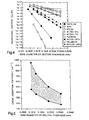
- Figure 4 shows the radiographic contrast versus outer diameter d2 in the Figure 1 configuration or sector thickness (t1 + t2) in the Figure 3 configuration for different material systems.
- the rectangular region defined by the solid lines along the x-axis-between 0.1016 to 0.2540 mm (0.0040 and 0.0100 inches) is a region of desired radiographic contrast.
- This region of desired radiographic contrast corresponds to ideal fluoroscopic conditions for stents composed of laminate layers in a tube configuration and for large diameter wire used in large diameter vessels such as an aortic or vena cava lumen.
- the rectangular region defined by the dotted lines along the x-axis in Figure 4 between 0.1270 to 0.1905 mm (0.0050 and 0.0075 inches) is a region of preferred radiographic contrast. This preferred region corresponds to ideal fluoroscopic conditions for coronary and peripheral stents composed of wire.
- Both the desirable and preferred radiographic contrast regions fall within the predetermined requisite radiographic contrast range along the y-axis of 1 x 10 -2 to 1 x 10 -4 .
- the radiographic contrast range of the present invention is particularly important in the case of stents which, when expanded, enter the vessel wall. After the resultant restenosis it is important to be able to see the vessel wall through the stent. For this reason, the endoprosthesis needs to be bright enough during X-ray fluoroscopy to be seen, but dim enough to be seen through. Being able to see through the endoprosthesis means that the X-ray signature from the endoprosthesis does not create an X-ray artifact which masks the surrounding vessel and tissue.
- the endoprostheses of the present invention are constructed to have a range of radiographic contrast between 1 x 10 -2 to 1 x 10 -4 , which strikes a balance between seeing the endoprosthesis and seeing the surrounding vessel wall or tissue during X-ray fluoroscopy.
- the sheath or outer tube 14 preferably has an outer diameter d2 ranging from 0.0508 to 0.3810 mm (0.0020 to 0.0150 inches). More preferably, the sheath 14 has an outer diameter d2 ranging from 0.1016 to 0.2540 mm (0.0040 to 0.0100 inches), as shown by the combined range of the desirable and preferred radiographic contrast regions in Figure 4. Even more preferably, the sheath 14 has an outer diameter d2 ranging from 0.1270 to 0.1905 mm (0.0050 to 0.0075 inches), as shown by the preferred dotted region in Figure 4. A core diameter d3 ranging from 0.0254 to 0.0635 mm (0.0010 to 0.0025 inches) achieves optimal radiographic contrast for all applications.
- the core and sheath diameters d1, d2 and d3 of the composite endoprosthesis 10 vary depending upon the intended use of the endoprosthesis 10.
- the outer diameter d2 ranges from 0.1270 to 0.1524 mm (0.0050 to 0.0060 inches).
- the outer diameter d2 ranges from 0.1397 to 0.1651 mm (0.0055 to 0.0065 inches).
- the outer diameter d2 ranges from 0.1905 to 0.2540 mm (0.0075 to 0.0100 inches).
- the laminate structure 16 has an overall size (t1 and t2) that varies depending upon the application of the endoprosthesis and may have the same sizes as the outer wire diameter d2 and the core diameter d3 discussed above.
- Figure 5 shows linear absorption coefficient as a function of wire diameter or section thickness.
- the shaded region shows the desired linear absorption coefficient across outer wire diameters d2 ranging from 0.1016 to 0.1905 mm (0.0040 to 0.0075 inches).
- Table I shows average atomic numbers, and hence elements that may be used, to form a composite endoprosthesis with radiographic contrast ranging from 1 x 10 -2 to 1 x 10 -4 .
- a unique and important characteristic of the present invention is its ability to use multiple materials that each exhibit superior performance for some of the required physical properties.
- the core is preferably selected to provide the composite endoprosthesis with good radiopacity while the sheath is preferably selected to provide the composite endoprosthesis with good physical properties.
- An endoprosthesis may thus be designed to have suitable radiographic contrast without adversely affecting the physical properties of the endoprosthesis.
- the first material includes one or more materials with an atomic number (elemental) or an average atomic number ranging from 24-71, as shown in Table I.
- the first material preferably includes one or more of gold, platinum, tantalum, iridium, tungsten, and alloys thereof.
- a preferred first material, tantalum may be obtained from the Cabot Corporation.
- the second material has chemical and physical properties that are compatible with the first material.
- the second material may be a nickel cobalt alloy such as an alloy including cobalt, carbon, manganese, silicon, phosphorus, sulfur, chromium, nickel, molybdenum, iron and titanium, or any combination thereof.
- Other materials may be used for the second material, such as an alloy including cobalt, carbon, manganese, silicon, chromium, nickel, phosphorus, molybdenum, sulfur and iron.
- composition for the second material is known as 304V (Registered Trade Mark) supplied by Carpenter Technology Corporation and has the following nominal composition (% by weight): carbon: 0.03 maximum; manganese: 2.00 maximum; silicon: 1.00 maximum; chromium: 18.0-20.0; nickel: 8.0-12.0; phosphorus: 0.045 maximum; sulphur: 0.03 maximum; with the balance being iron.
- 304V Registered Trade Mark
- composition for the second material is known as 316 LVM (Registered Trade Mark) supplied by Carpenter Technology Corporation and includes the following nominal composition (% by weight): carbon: 0.03 maximum; manganese: 2.00 maximum; silicon: 1.00 maximum; chromium: 16.0-18.0; nickel: 10.0-14.0%; phosphorus: 0.045% maximum; sulfur: 0.03% maximum; molybdenum: 2.0-3.0; with the balance being iron.
- 316 LVM Registered Trade Mark
- a preferred composition for the second material is known as MP35N (a Registered Trade Mark and supplied by Carpenter Technology Corporation and the Latrobe Steel Company) and has the following nominal composition (% by weight): carbon: 0.025 maximum; manganese: 0.15 maximum; silicon: 0.15 maximum; phosphorus: 0.015 maximum; sulfur: 0.010 maximum; chromium: 19.0-21.0 maximum; nickel: 33.0-37.0; molybdenum: 9.0-10.5; iron: 1.0 maximum; titanium: 1.0 maximum; with the balance being cobalt.
- MP35N a Registered Trade Mark and supplied by Carpenter Technology Corporation and the Latrobe Steel Company
- the first material is present in an amount of 2-9 % by volume based on the combined volume of the first and second materials.
- One preferred composite material includes 91 volume % MP35N and 9 volume % Ta.
- Other preferred composite materials include either 93 volume % MP35N and 7 volume % Ta or 96 volume % MP35N and 4 volume % Ta. These materials exhibit radiographic contrasts that fall completely within the preferred dotted region across wire diameters in the range of from 0.1270 to 0.1905 mm (0.0050 to 0.0075 inches).
- endoprosthesis materials are those that comprise only tantalum or platinum and a material including 67 volume % MP35N and 33 volume % Ta (MP35N-33Ta). These materials have X-ray fluoroscopic signatures that are generally too bright for the surrounding tissue or vessel wall to be seen.
- the lower limit of the desirable region of wire diameter is shown as 0.1016 mm (0.0040 inches) in Figure 4, a wire diameter of 0.1270 mm (0.0050 inches) or more is preferable. At wire diameters under 0.1270 (0.0050 inches), the endoprosthesis does not possess desirable hoop strength. A minimum hoop strength of 100 mm of Hg must be maintained for an endoprosthesis. An endoprosthesis having the configuration shown in Figure 1 should have a 0.1016 mm (0.0040 inch) diameter or greater to satisfy this hoop strength. An endoprosthesis having the configuration shown in Figure 3 may require a thickness of 0.0762 or 0.0508 mm (0.0030 or 0.0020 inches) to satisfy this hoop strength.
- the MP35N-33Ta composition and other materials with a high radiopaque material content may have acceptable radiographic contrast under 0.1270 mm (0.0050 inches) in wire diameter as shown in Figure 4, it may not be feasible to make endoprostheses from such materials, due to their undesirably low hoop strengths.
- an endoprosthesis composed of a single material system such as one of palladium, MP35N or 304V falls within the region of acceptable radiographic contrast as shown in Figure 4, these materials have certain drawbacks.
- Palladium is toxic in the human body and would require a protective coating to be usable.
- An endoprosthesis comprising either MP35N or 304V alone only has acceptable contrast for wire diameters in excess of about 0.1524 mm (0.0060 inches), which prevents these materials from being used for coronary stents.
- Iron-based materials are undesirable in the endoprosthesis of the present invention when present in excessive amounts.
- One such iron-based material that is undesirable for use in the present invention has the brand name of Elgiloy (Registered Trade Mark), and may be obtained from the Carpenter Technology Corporation.
- Such iron-containing stents in the body undesirably heat up and move when an MRI Spiral CT is performed on the patient.
- the endoprostheses of the present invention are made by obtaining composite filaments manufactured by a drawn filled tubing ("DFT") process such as that performed by Ft. Wayne Metals Research Products Corporation of Ft. Wayne, Indiana.
- a tube made of the second material has an inner diameter that permits a core wire made of the first material to be inserted into it and to be substantially radially centered in the tube.
- the inner and outer diameters of the tube and the diameter of the core wire vary depending on the materials used.
- the inside and outside diameter of the sheath material and the outside diameter of the core material at the start of the manufacturing process vary based upon the particular starting material and the desired percent by volume of the core.
- the tube and core wire may be at least twenty feet in length.
- the core wire is inserted into a central opening of the tube to form a composite filament.
- the filament then undergoes a plurality of alternating cold working and annealing steps.
- the filament may be drawn through three dies. In each die, the filament is cold worked in radial compression, which causes it to flow, thereby reducing its diameter and increasing its length.
- the tube may be radially reduced and lengthened more rapidly than the wire at first, due to a gap initially present between the wire and the tube. After the gap is closed, the core wire and tube are radially reduced and lengthened at substantially the same rate.
- each of the dies Passing through each of the dies induces strain hardening and other stresses into the filament, which are removed by one or more annealing steps.
- the filaments are heated at a temperature ranging from about 1038 to about 1260 °C (1900 to about 2300 °F).
- Each annealing step removes nearly all of the induced stresses from the filament.
- Each annealing step may last between, for example, 1 to 30 seconds at the annealing temperature, depending on the size of the filament.
- the number of cold working and annealing steps depends on the initial filament size, the materials used and the desired radial reduction.
- the composite material is drawn down in successive dies at a 10 % reduction in area per die. Between each annealing cycle there is a 30 to 50 % reduction in area.
- the resulting endoprosthesis may then be formed into a stent by a process known to those skilled in the art, such as that described in U.S. Patent Application Serial No. 08/123,440 to Williams, entitled “Endoprosthesis Having Laser Welded Junctions, Method and Procedure,” filed June 16, 1995.
- the laminate hypotube may be manufactured by one of two processes.
- the hypotube may be produced by hot rolling a series of layers of material into a laminate sheet.
- Each layer includes one or more layers of the second structural material such as MP35N and one or more layers of the first radiopaque material such as tantalum.
- the hot rolling process may be optimized to ensure mechanical bonding between the multiple layers and that the composite material has a tensile strength ranging from 483 to 827 MPa (70,000 to 120,000 psi) with 5 to 30 percent elongation. Elongation is defined as the percent increase in the length of a component prior to failure when a tensile load is applied to the component.
- the laminate sheets may then be rolled up around a mandrel and seam welded to form a tube. The seam welded tube can then be drawn to final size.
- the second process for making the hypotube is to place multiple layers of tubes within each other around a core mandrel.
- the composite structure may then be drawn and heat treated using conventional wire drawing practices until the finished tube diameter meets the physical properties and dimensions required.
- a sacrificial ductile core mandrel is placed within the hypotube prior to the wire drawing process.
- the composite system is then drawn to finish dimensions and the core mandrel is removed. Removal of the mandrel is achieved by reducing the cross section of the mandrel. By solely pulling the mandrel, the diameter of the mandrel can be reduced sufficiently to be easily removed.
- the structure may be loaded onto a lathe type tool and windows may be cut from this tube using, for example, a laser, a cutting tool, a water saw, or an electron discharge machining ("EDM”) process.
- EDM electron discharge machining
- a wire is used as a cutting tool and placed in contact with the part.
- An electrical pulse is transferred through the wire and an electrical discharge occurs, burning a fine cut in the part.
- the EDM process accurately cuts the part without inducing stresses in it.
- the tube may then be deburred by a procedure such as shot peening, abrasive tumbling, honing, electropolishing and electroetching.
- the windows are important to the function of the endoprosthesis.
- the endoprosthesis is in the form of a stent
- the stent is required to be crimped down onto a balloon catheter at a size smaller than the original hypotube and deployed to a size at less than twice the diameter of the hypotube.
- regions need to exist within the endoprosthesis where plastic deformation can result in thin sections allowing the expansion and contraction of the endoprosthesis to occur at a low pressure of approximately 2 atmospheres.
- the core and sheath materials are preferably selected to have physical properties, such as coefficients of thermal expansion, annealing temperature ranges, and elastic moduli, which are compatible with each other. Matching the Young's Moduli of the core and sheath materials is well within the ability of those skilled in the art in view of the instant disclosure, and is an important part of developing the material of the present invention.
- the component with the largest cross-sectional area must have a Young's Modulus equal or greater to the Young's Modulus of the other component. If this does not occur, the multiple layers of the endoprosthesis will delaminate during the manufacturing process or during in vivo use.
- the endoprosthesis material must also be biocompatible and not toxic so that it will not result in an inflammatory reaction from the body.
- Important mechanical properties for the endoprostheses of the present invention are toughness, tensile strength and hoop strength.
- the composite structure or alloy must have sufficient toughness, i.e., enough resistance to failure to prevent the initiation and propagation of cracks during the stress history of the endoprosthesis.
- the stress history includes the application of a load during the manufacturing process and during deployment, and cyclic loading in the human body.
- the endoprothesis may have a toughness ranging from 20 to 120 joules.
- the endoprosthesis, or a stent, for example, that is made from the endoprosthesis be plastically deployed by a balloon.
- Such an endoprosthesis or a stent made therefrom has an ultimate tensile strength in the range of 552 to 965 MPa (80,000 to 140,000 psi) and 10% minimum elongation and, more preferably, an ultimate tensile strength of 552 to 758 MPa (80,000 to 110,000 psi).
- a minimum hoop strength of 100 mm of Hg is required to keep a vessel open.
- the surface of the sheath or outer laminates is preferably free of imperfections with a surface finish of no more than 762 nm (30 ⁇ in) roughness. Such a surface finish minimizes the development of crack nucleation sites on the surface of the endoprosthesis. A defect-free surface minimizes the incidence of fatigue failure as well as the possibility of thrombus generation and tissue inflammation.
- the composite material must also be corrosion resistant as specified in the document, Guidance for the submission of Research and Marketing Applications For Interventional Cardiology Devices: PTCA Catheters Atherectomy Catheters Lasers Intervascular Stents, the Interventional Cardiology Branch Division of Cardiovascular, Respiratory and Neurological devices Office of Device Evaluation, May 1994.
- the composite structure is preferably sufficiently noble to prevent surface corrosion from degrading the endoprothesis, and must prevent crevice corrosion or galvanic corrosion from degrading the endoprothesis between the layers.
Description
- The present invention relates to endoprostheses, and in particular, to endoprostheses made of composite materials having radiographic contrast suitable for detection by X-ray fluoroscopy with minimal interference in rendering Quantitative Coronary Angiographic Analysis.
- One type of endoprosthesis device, commonly referred to as a stent, is placed or implanted within a blood vessel for treating stenoses, strictures, or aneurysms in the blood vessel. These devices are implanted within the vascular system to reinforce diseased, partially occluded, weakened or abnormally dilated sections of the blood vessel. Stents also have been successfully implanted in the urinary tract or the bile ducts to reinforce and prevent neoplastic growth in blood vessels. One common procedure for implanting the stent is to wrap the stent around a balloon catheter, to place the stent in the diseased portion of the vessel, for example, and then to inflate the balloon to secure the stent in place in the vessel.
- Stents must be manufacturable and have suitable physical properties including suitable radiopacity, biocompatibility, and mechanical properties such as hoop strength, fatigue resistance, and corrosion resistance. Many stents today are composed of stainless steel or other metals which in their product thickness are not easily detectable using X-ray fluoroscopy. Stents have been constructed from tantalum wire, as disclosed in U.S. Patent No. 5,135,536. However, tantalum wire is very radiopaque and thus, produces a very bright X-ray fluoroscopy image, which obscures the resulting X-ray image resulting from the surrounding tissue and prevents the use of Quantitative Coronary Angiographic techniques for lumen size determination.
- It is currently difficult to alter the radiopacity of an endoprosthesis without changing its physical properties. Physical properties of the endoprosthesis are very important. Some stents have very limited compliance characteristics, making them not particularly well suited for use in curved vessel pathways. For example, using stents having a generally rigid cylindrical shape in curved vessel pathways typically requires the stents to have a very short length and to be strung out along the curved pathway. Also, such stents are often delivered separately, thereby increasing the invasiveness of the procedure.
- Previous approaches in endoprosthesis construction have used devices with good hoop strength. When stents are provided in relatively large vessels or deployed within a vessel susceptible to external forces, such as within the leg, good hoop strength is important to resist forces which tend to collapse the endoprosthesis.
- WO 95/30384 discloses such an endoprosthesis, comprising two materials in a composite, wherein the first material forms a highly radiopaque core and the second material acts as a surrounding case, exhibiting high yield strength, such that the whole endoprosthesis exhibits high overall yield strength of at least 1 GPa (150,000 psi).
- WO 94/16646 discloses a process for manufacturing the endoprothesis disclosed in WO 95/30384.
- WO 93/19803 discloses a medical device having a metal outer member and an inner core with low elasticity, for enhancing the radiopacity of the device, the core being present in an amount of between 10 to 50% of the device by volume.
- Other endoprostheses exhibit less hoop strength but are more compliant and are better suited to conform to the contour of the vessel, rather than being so non-conforming as to misshape the vessel after deployment. A typical disadvantage of more compliant stent devices is that they tend to deform upon or after deployment and present stenting surfaces that can lack desirable uniformity throughout the working surface area of the stent. A non-uniform working surface area of the stent is especially evident during expansion of the stent from its collapsed, insertion diameter to its expanded, implanted diameter. At times, this lack of uniformity upon expansion is exacerbated by folds or other nonuniformities in the balloon on which the stent is mounted for deployment.
- The present invention is directed to a composite material endoprosthesis with predetermined radiopacity characteristics that do not compromise the physical properties of the endoprosthesis.
- In general, the invention relates to an endoprosthesis including a body structure formed of a biocompatible material. The body structure includes a first material having an average atomic number greater than 24 and a second material that is different than the first material. The first material is present in an amount not greater than 9% by volume based on the combined volume of the first material and the second material. The body structure has a mass absorption coefficient effective to provide a ratio of an intensity of an incident X-ray to an intensity of a transmitted X-ray in a range of 1 x 10⁻² to 1 x 10⁻⁴. More specifically, either the endoprosthesis itself or a stent made from this material has a tensile strength of 552 to 965 MPa (80,000-140,000 pounds per square inch ("psi")) with a minimum elongation of 10 percent.
- In a preferred embodiment, the body structure includes an elongated central cylindrical core and an elongated outer tubular member disposed around the core. One of the first and second materials comprises the core and the other comprises the tubular member. It is preferred that the first material comprise the core and the second material comprise the tubular member. However, an endoprosthesis may be constructed to have a tubular member comprised of the first material with a core comprised of the second material.
- Instead of having a tubular member and core, the body structure may include one or more generally planar layers, one of the first and second materials comprising one of the layers and the other comprising another of the layers. The body structure may also be in the form of a cylindrical tube comprising a central layer along with at least one sheath disposed around the central layer. The central layer is comprised of the first material and the sheath is comprised of the second material.
- The first material preferably comprises one or more of gold, platinum, tantalum, iridium, tungsten, and alloys thereof. The second material may be a cobalt alloy such as an alloy including cobalt, carbon, manganese, silicon, phosphorus, sulfur, chromium, nickel, molybdenum, titanium and iron, or any combination thereof. Other materials may be used for the second material, such as an alloy including cobalt, carbon, manganese, silicon, chromium, nickel, phosphorus, molybenum, iron and sulfur.
- Certain materials are not preferred for use in the endoprostheses of the present invention. For example, when present in excessive amounts, palladium, copper, zinc and lead are toxic in the human body and would require a protective coating to be usable. Magnetic or ferromagnetic materials are undesirable for use in the endoprostheses of the present invention when used in excessive amounts. When a patient has a stent made of a magnetic or ferromagnetic material in the body, the use of Magnetic Resonance Imaging ("MRI") could be a problem since the stent may cause an artifact of the MRI image, be displaced by the magnetic field or heat up in the magnetic field. This prevents stents made of magnetic and ferromagnetic materials from being used in the brain for which an MRI Spiral Computerized Tomography ("CT") procedure is commonly performed.
- Selecting the size of the tubular member is important for achieving the desired radiographic contrast depending upon the particular application. The tubular member has an outer diameter ranging from 0.0508 to 0.3810 mm (0.0020 to 0.0150 inches) and, more preferably, an outer diameter ranging from 0.1016 to 0.2540 mm (0.0040 to 0.0100 inches). Even more preferably, the outer diameter of the tubular member ranges from 0.1270 to 0.1905 mm (0.0050 to 0.0075 inches). The core has a diameter ranging from 0.0127 to 0.0762 mm (0.0005 to 0.0030 inches).
- The present invention avoids the problems of conventional endoprostheses materials having fluoroscopic signatures that are either too dim such as observed with stainless steel endoprostheses, or are too bright as in the case of endoprostheses comprising only tantalum. The endoprostheses of the present invention obtain good radiographic contrast without adversely altering their necessary physical properties. The radiographic contrast is obtained by selecting the mass absorption coefficient to provide a ratio of an intensity of an incident X-ray to an intensity of a transmitted X-ray in a range of 1 x 10⁻² to 1 x 10⁻⁴. Thus, the endoprostheses of the present invention are bright enough to be seen during X-ray fluoroscopy but dim enough to allow the surrounding vessel or tissue to be seen through the endoprostheses and to perform Quantitative Coronary Angiography techniques.
- The endoprostheses of the present invention are suitable for any application in which tailored radiographic contrast and physical properties are desirable. The endoprostheses may be formed into different sizes and shapes, as well as with different physical properties, depending upon where they are used in the body. The endoprostheses may advantageously be used to form coronary stents, peripheral stents, stent grafts and the like. The endoprostheses of the invention may also be used to form suture clips, vena cava filters, heart valves, guidewires and tube stiffening systems such as Palmaz (Registered Trade Mark) stents by Johnson & Johnson Interventional Systems.
- Other embodiments of the invention are contemplated to provide particular features and structural variants of the basic elements. The specific embodiments referred to as well as possible variations and the various features and advantages of the invention will become better understood from the detailed description that follows, together in connection with the accompanying drawings.
-
- Figure 1 is a perspective cross-sectional view showing one embodiment of an endoprosthesis constructed in accordance with the present invention;
- Figure 2 is a perspective cross-sectional view showing another embodiment of an endoprosthesis constructed in accordance with the present invention;
- Figure 3 is an endoprosthetic tube formed from the endoprosthesis shown in Figure 2;
- Figure 4 is a graph showing radiographic contrast as a function of wire diameter or section thickness; and
- Figure 5 is a graph showing linear absorption coefficient as a function of wire diameter or section thickness.
-
- Turning now to the drawings, Figure 1 shows one form of an
endoprosthesis 10 having a body structure including a biocompatible material. Eachendoprosthesis 10 of the present invention has a composition that preferably includes two or more materials, a radiopaque first material and a second material that is different than the first material and imparts certain properties to the body structure. - The body structure is preferably in the form of an elongated wire member including a central
cylindrical core 12 and an outertubular sheath 14 disposed around thecore 12. Thecore 12 and thesheath 14 both have a generally uniform transverse cross-sectional area along their lengths. Thesheath 14 has an inner diameter d1 and an outer diameter d2. The inner diameter d1 of thesheath 14 is of a size sufficient to accommodate thecore 12, which has a diameter d3. The body structure may have additional, generally annular layers disposed radially outside thesheath 14 or between thesheath 14 and thecore 12. Alternatively, the body member may be formed from a single composite material as a solid cylindrical wire without a tubular sheath and a central cylindrical core. - Figure 2 shows another form of the
endoprosthesis 10 of the present invention, including alaminate structure 16 having first andsecond layers first layer 18 has a thickness t1 and thesecond layer 20 has a thickness t2. Additional layers may also be used either between or outside the first andsecond layers - A
cylindrical hypotube 22 shown in Figure 3 may be formed from thelaminate structure 16 of Figure 2. In the hypotube configuration shown in Figure 3, thelayer 18 forms an inner tubular layer and thelayer 20 forms an outer tubular layer. - Openings or
windows 24 may be formed in the walls of thehypotube 22. The windows are preferably cut from thecomposite tube 22 to allow the endoprosthesis to be expandable to different diameters. The windows allow beam sections to develop between windows which will have elastic and plastic zones, which is consistent with the stent configuration by Palmaz developed by Johnson and Johnson Interventional Systems. - It is important to be able to detect the position of the
endoprosthesis 10 using X-ray fluoroscopy or Magnetic Resonance Imaging during deployment and post deployment inspections of the endoprosthesis. Theendoprosthesis 10 is detected when the material in the endoprosthesis body structure absorbs a sufficient intensity of a transmitted X-ray beam to be detected as a different intensity than the intensity of an initial X-ray beam. This relationship is empirically presented by the following equation: - Ix is the intensity of the transmitted X-ray beam after passing through a thickness x;
- I0 is the intensity of the incident X-ray beam;
- µ/ρ is the mass absorption coefficient of the endoprosthesis;
- µ is the linear absorption coefficient;
- ρ is the density of the endoprosthesis; and
- x is the thickness or diameter of the endoprosthesis.
-
- The mass absorption coefficient of the
composite endoprosthesis 10 used inEquation 1 is determined by summing the weight fractions of the mass absorption coefficients of each elemental component of the complete endoprosthesis. The mass absorption coefficient of each elemental component is related to the X-ray wavelength of the incident X-ray and the atomic number of each elemental component as follows: - µ/ρ is the mass absorption coefficient of each elemental component;
- k is a constant;
- X is the X-ray wavelength; and
- Z is the atomic number of each elemental component. By summing the elemental weight fraction multiplied by the elemental atomic number and the X-ray fluoroscope X-ray wavelength, for each element in the composite endoprosthesis, the mass absorption coefficient of the entire composite endoprosthesis can be determined.
-
- Radiographic contrast is the difference in X-ray intensity transmitted through one interaction area of a material as compared to that transmitted through another interaction area of the material. Radiographic contrast is the relationship between the transmitted X-ray beam through the endoprosthesis and the transmitted X-ray beam through the surrounding tissue. Radiographic contrast for an endoprosthesis is defined as follows:
- Is is the intensity of the X-ray beam transmitted through the endoprosthesis; and
- Il is the intensity of the X-ray beam through tissue. The X-ray intensity of the
-
- The present invention permits the radiographic contrast of the endoprosthesis to be predetermined by controlling the mass absorption coefficient. The mass absorption coefficient is controlled by selecting the composite material used and the thickness or diameter of the entire endoprosthesis, ie., d2 or t1+t2. By using preferably two or more materials, each having different physical properties, the radiographic contrast may be adjusted as desired without altering the physical properties of the entire endoprosthesis including fatigue resistance, corrosion resistance, tensile strength, toughness and biocompatibility. This is because by employing a structure having a tubular member and core, for example, the amount of the radiopaque material in the core can be adjusted while maintaining the amount of the structural material in the tubular member needed for the requisite physical properties.
- The mass absorption coefficients must be carefully selected to produce a radiographic contrast within a preferred range. It is important to design the composite structure so that the fluoroscopy signature of the endoprosthesis is adequately detectable or bright, and yet does not develop an X-ray artifact which interferes with X-ray signatures of the vessel wall. In other words, the X-ray fluoroscopy images of the radiopaque materials must not be excessively bright. Experimental studies on the radiopacity of endoprostheses of the present invention using adult mongrel canine and pygmy swine porcine have indicated that the ideal fluoroscopic signature correlates to a radiographic contrast in a range of 1 x 10⁻² to 1 x 10⁻⁴. This contrast range provides sufficient intensity to detect the endoprosthesis without, for example, altering quantitative angiographic measurement.
- Figure 4 shows the radiographic contrast versus outer diameter d2 in the Figure 1 configuration or sector thickness (t1 + t2) in the Figure 3 configuration for different material systems. The rectangular region defined by the solid lines along the x-axis-between 0.1016 to 0.2540 mm (0.0040 and 0.0100 inches) is a region of desired radiographic contrast. This region of desired radiographic contrast corresponds to ideal fluoroscopic conditions for stents composed of laminate layers in a tube configuration and for large diameter wire used in large diameter vessels such as an aortic or vena cava lumen.
- The rectangular region defined by the dotted lines along the x-axis in Figure 4 between 0.1270 to 0.1905 mm (0.0050 and 0.0075 inches) is a region of preferred radiographic contrast. This preferred region corresponds to ideal fluoroscopic conditions for coronary and peripheral stents composed of wire. The following description herein, unless otherwise indicated, refers to the wire embodiment shown in Figure 1, although it is equally applicable to the laminate and hypotube embodiments shown in Figures 2 and 3.
- Both the desirable and preferred radiographic contrast regions fall within the predetermined requisite radiographic contrast range along the y-axis of 1 x 10⁻² to 1 x 10⁻⁴. The radiographic contrast range of the present invention is particularly important in the case of stents which, when expanded, enter the vessel wall. After the resultant restenosis it is important to be able to see the vessel wall through the stent. For this reason, the endoprosthesis needs to be bright enough during X-ray fluoroscopy to be seen, but dim enough to be seen through. Being able to see through the endoprosthesis means that the X-ray signature from the endoprosthesis does not create an X-ray artifact which masks the surrounding vessel and tissue. This allows an accurate measurement of the vessel lumen size after implantation. At radioscopic contrast greater than 1 x 10⁻² the endoprosthesis is too dim for the endoprosthesis to be seen. X-ray images showing the radiographic contrast of 1 x 10⁻² were observed in a canine study of the endoprostheses of the present invention at the Institut de Cardiologie de Montreal and were presented on a real time video and on X-ray film. At radiographic contrast less than 1 x 10⁻⁴ the endoprosthesis is too bright for the surrounding tissue or vessel wall to be seen. Thus, the endoprostheses of the present invention are constructed to have a range of radiographic contrast between 1 x 10⁻² to 1 x 10⁻⁴, which strikes a balance between seeing the endoprosthesis and seeing the surrounding vessel wall or tissue during X-ray fluoroscopy.
- The sheath or
outer tube 14 preferably has an outer diameter d2 ranging from 0.0508 to 0.3810 mm (0.0020 to 0.0150 inches). More preferably, thesheath 14 has an outer diameter d2 ranging from 0.1016 to 0.2540 mm (0.0040 to 0.0100 inches), as shown by the combined range of the desirable and preferred radiographic contrast regions in Figure 4. Even more preferably, thesheath 14 has an outer diameter d2 ranging from 0.1270 to 0.1905 mm (0.0050 to 0.0075 inches), as shown by the preferred dotted region in Figure 4. A core diameter d3 ranging from 0.0254 to 0.0635 mm (0.0010 to 0.0025 inches) achieves optimal radiographic contrast for all applications. - The core and sheath diameters d1, d2 and d3 of the
composite endoprosthesis 10 vary depending upon the intended use of theendoprosthesis 10. When theendoprostheses 10 are used to form coronary stents, the outer diameter d2 ranges from 0.1270 to 0.1524 mm (0.0050 to 0.0060 inches). For use in saphenous vein grafts the outer diameter d2 ranges from 0.1397 to 0.1651 mm (0.0055 to 0.0065 inches). For peripheral stents, such as for use in iliac and biliary lumens, for use in the brain, and for abdominal aortic aneurysms, the outer diameter d2 ranges from 0.1905 to 0.2540 mm (0.0075 to 0.0100 inches). Thelaminate structure 16 has an overall size (t1 and t2) that varies depending upon the application of the endoprosthesis and may have the same sizes as the outer wire diameter d2 and the core diameter d3 discussed above. - Figure 5 shows linear absorption coefficient as a function of wire diameter or section thickness. The shaded region shows the desired linear absorption coefficient across outer wire diameters d2 ranging from 0.1016 to 0.1905 mm (0.0040 to 0.0075 inches).
- The following Table I shows average atomic numbers, and hence elements that may be used, to form a composite endoprosthesis with radiographic contrast ranging from 1 x 10⁻² to 1 x 10⁻⁴.
Wire Diameter or Section Thickness / mm (inch) Average atomic number 0.1016 (0.0040) 63-71 0.1270 (0.0050) 28-70 0.1905 (0.0075) 26-64 0.2540 (0.0100) 24-27 - A unique and important characteristic of the present invention is its ability to use multiple materials that each exhibit superior performance for some of the required physical properties. The core is preferably selected to provide the composite endoprosthesis with good radiopacity while the sheath is preferably selected to provide the composite endoprosthesis with good physical properties. An endoprosthesis may thus be designed to have suitable radiographic contrast without adversely affecting the physical properties of the endoprosthesis.
- The first material includes one or more materials with an atomic number (elemental) or an average atomic number ranging from 24-71, as shown in Table I. For example, the first material preferably includes one or more of gold, platinum, tantalum, iridium, tungsten, and alloys thereof. A preferred first material, tantalum, may be obtained from the Cabot Corporation.
- The second material has chemical and physical properties that are compatible with the first material. The second material may be a nickel cobalt alloy such as an alloy including cobalt, carbon, manganese, silicon, phosphorus, sulfur, chromium, nickel, molybdenum, iron and titanium, or any combination thereof. Other materials may be used for the second material, such as an alloy including cobalt, carbon, manganese, silicon, chromium, nickel, phosphorus, molybdenum, sulfur and iron.
- One composition for the second material is known as 304V (Registered Trade Mark) supplied by Carpenter Technology Corporation and has the following nominal composition (% by weight): carbon: 0.03 maximum; manganese: 2.00 maximum; silicon: 1.00 maximum; chromium: 18.0-20.0; nickel: 8.0-12.0; phosphorus: 0.045 maximum; sulphur: 0.03 maximum; with the balance being iron.
- Another composition for the second material is known as 316 LVM (Registered Trade Mark) supplied by Carpenter Technology Corporation and includes the following nominal composition (% by weight): carbon: 0.03 maximum; manganese: 2.00 maximum; silicon: 1.00 maximum; chromium: 16.0-18.0; nickel: 10.0-14.0%; phosphorus: 0.045% maximum; sulfur: 0.03% maximum; molybdenum: 2.0-3.0; with the balance being iron.
- A preferred composition for the second material is known as MP35N (a Registered Trade Mark and supplied by Carpenter Technology Corporation and the Latrobe Steel Company) and has the following nominal composition (% by weight): carbon: 0.025 maximum; manganese: 0.15 maximum; silicon: 0.15 maximum; phosphorus: 0.015 maximum; sulfur: 0.010 maximum; chromium: 19.0-21.0 maximum; nickel: 33.0-37.0; molybdenum: 9.0-10.5; iron: 1.0 maximum; titanium: 1.0 maximum; with the balance being cobalt.
- In the composite body structure of the present invention the first material is present in an amount of 2-9 % by volume based on the combined volume of the first and second materials. One preferred composite material includes 91 volume % MP35N and 9 volume % Ta. Other preferred composite materials include either 93 volume % MP35N and 7 volume % Ta or 96 volume % MP35N and 4 volume % Ta. These materials exhibit radiographic contrasts that fall completely within the preferred dotted region across wire diameters in the range of from 0.1270 to 0.1905 mm (0.0050 to 0.0075 inches).
- Other endoprosthesis materials are those that comprise only tantalum or platinum and a material including 67 volume % MP35N and 33 volume % Ta (MP35N-33Ta). These materials have X-ray fluoroscopic signatures that are generally too bright for the surrounding tissue or vessel wall to be seen.
- Although the lower limit of the desirable region of wire diameter is shown as 0.1016 mm (0.0040 inches) in Figure 4, a wire diameter of 0.1270 mm (0.0050 inches) or more is preferable. At wire diameters under 0.1270 (0.0050 inches), the endoprosthesis does not possess desirable hoop strength. A minimum hoop strength of 100 mm of Hg must be maintained for an endoprosthesis. An endoprosthesis having the configuration shown in Figure 1 should have a 0.1016 mm (0.0040 inch) diameter or greater to satisfy this hoop strength. An endoprosthesis having the configuration shown in Figure 3 may require a thickness of 0.0762 or 0.0508 mm (0.0030 or 0.0020 inches) to satisfy this hoop strength. Therefore, although the MP35N-33Ta composition and other materials with a high radiopaque material content may have acceptable radiographic contrast under 0.1270 mm (0.0050 inches) in wire diameter as shown in Figure 4, it may not be feasible to make endoprostheses from such materials, due to their undesirably low hoop strengths.
- Although an endoprosthesis composed of a single material system such as one of palladium, MP35N or 304V falls within the region of acceptable radiographic contrast as shown in Figure 4, these materials have certain drawbacks. Palladium is toxic in the human body and would require a protective coating to be usable. An endoprosthesis comprising either MP35N or 304V alone only has acceptable contrast for wire diameters in excess of about 0.1524 mm (0.0060 inches), which prevents these materials from being used for coronary stents.
- Iron-based materials are undesirable in the endoprosthesis of the present invention when present in excessive amounts. One such iron-based material that is undesirable for use in the present invention has the brand name of Elgiloy (Registered Trade Mark), and may be obtained from the Carpenter Technology Corporation. Such iron-containing stents in the body undesirably heat up and move when an MRI Spiral CT is performed on the patient.
- The endoprostheses of the present invention are made by obtaining composite filaments manufactured by a drawn filled tubing ("DFT") process such as that performed by Ft. Wayne Metals Research Products Corporation of Ft. Wayne, Indiana. A tube made of the second material has an inner diameter that permits a core wire made of the first material to be inserted into it and to be substantially radially centered in the tube. The inner and outer diameters of the tube and the diameter of the core wire vary depending on the materials used. The inside and outside diameter of the sheath material and the outside diameter of the core material at the start of the manufacturing process vary based upon the particular starting material and the desired percent by volume of the core. The tube and core wire may be at least twenty feet in length. The core wire is inserted into a central opening of the tube to form a composite filament.
- The filament then undergoes a plurality of alternating cold working and annealing steps. For example, the filament may be drawn through three dies. In each die, the filament is cold worked in radial compression, which causes it to flow, thereby reducing its diameter and increasing its length. The tube may be radially reduced and lengthened more rapidly than the wire at first, due to a gap initially present between the wire and the tube. After the gap is closed, the core wire and tube are radially reduced and lengthened at substantially the same rate.
- Passing through each of the dies induces strain hardening and other stresses into the filament, which are removed by one or more annealing steps. In each of the annealing steps the filaments are heated at a temperature ranging from about 1038 to about 1260 °C (1900 to about 2300 °F). Each annealing step removes nearly all of the induced stresses from the filament. Each annealing step may last between, for example, 1 to 30 seconds at the annealing temperature, depending on the size of the filament. The number of cold working and annealing steps depends on the initial filament size, the materials used and the desired radial reduction. In the wire drawing process, the composite material is drawn down in successive dies at a 10 % reduction in area per die. Between each annealing cycle there is a 30 to 50 % reduction in area.
- The resulting endoprosthesis may then be formed into a stent by a process known to those skilled in the art, such as that described in U.S. Patent Application Serial No. 08/123,440 to Williams, entitled "Endoprosthesis Having Laser Welded Junctions, Method and Procedure," filed June 16, 1995.
- The laminate hypotube may be manufactured by one of two processes. In the first process the hypotube may be produced by hot rolling a series of layers of material into a laminate sheet. Each layer includes one or more layers of the second structural material such as MP35N and one or more layers of the first radiopaque material such as tantalum. The hot rolling process may be optimized to ensure mechanical bonding between the multiple layers and that the composite material has a tensile strength ranging from 483 to 827 MPa (70,000 to 120,000 psi) with 5 to 30 percent elongation. Elongation is defined as the percent increase in the length of a component prior to failure when a tensile load is applied to the component. The laminate sheets may then be rolled up around a mandrel and seam welded to form a tube. The seam welded tube can then be drawn to final size.
- The second process for making the hypotube is to place multiple layers of tubes within each other around a core mandrel. The composite structure may then be drawn and heat treated using conventional wire drawing practices until the finished tube diameter meets the physical properties and dimensions required. A sacrificial ductile core mandrel is placed within the hypotube prior to the wire drawing process. The composite system is then drawn to finish dimensions and the core mandrel is removed. Removal of the mandrel is achieved by reducing the cross section of the mandrel. By solely pulling the mandrel, the diameter of the mandrel can be reduced sufficiently to be easily removed.
- Once a composite hypotube is obtained, the structure may be loaded onto a lathe type tool and windows may be cut from this tube using, for example, a laser, a cutting tool, a water saw, or an electron discharge machining ("EDM") process. In the EDM process a wire is used as a cutting tool and placed in contact with the part. An electrical pulse is transferred through the wire and an electrical discharge occurs, burning a fine cut in the part. The EDM process accurately cuts the part without inducing stresses in it. Once the windows are cut from the tube, the tube may then be deburred by a procedure such as shot peening, abrasive tumbling, honing, electropolishing and electroetching.
- The windows are important to the function of the endoprosthesis. When the endoprosthesis is in the form of a stent, the stent is required to be crimped down onto a balloon catheter at a size smaller than the original hypotube and deployed to a size at less than twice the diameter of the hypotube. To achieve this task, regions need to exist within the endoprosthesis where plastic deformation can result in thin sections allowing the expansion and contraction of the endoprosthesis to occur at a low pressure of approximately 2 atmospheres.
- The core and sheath materials are preferably selected to have physical properties, such as coefficients of thermal expansion, annealing temperature ranges, and elastic moduli, which are compatible with each other. Matching the Young's Moduli of the core and sheath materials is well within the ability of those skilled in the art in view of the instant disclosure, and is an important part of developing the material of the present invention. The component with the largest cross-sectional area must have a Young's Modulus equal or greater to the Young's Modulus of the other component. If this does not occur, the multiple layers of the endoprosthesis will delaminate during the manufacturing process or during in vivo use. The endoprosthesis material must also be biocompatible and not toxic so that it will not result in an inflammatory reaction from the body.
- Important mechanical properties for the endoprostheses of the present invention are toughness, tensile strength and hoop strength. The composite structure or alloy must have sufficient toughness, i.e., enough resistance to failure to prevent the initiation and propagation of cracks during the stress history of the endoprosthesis. The stress history includes the application of a load during the manufacturing process and during deployment, and cyclic loading in the human body. The endoprothesis may have a toughness ranging from 20 to 120 joules.
- It is preferred that the endoprosthesis, or a stent, for example, that is made from the endoprosthesis, be plastically deployed by a balloon. Such an endoprosthesis or a stent made therefrom has an ultimate tensile strength in the range of 552 to 965 MPa (80,000 to 140,000 psi) and 10% minimum elongation and, more preferably, an ultimate tensile strength of 552 to 758 MPa (80,000 to 110,000 psi). A minimum hoop strength of 100 mm of Hg is required to keep a vessel open.
- The surface of the sheath or outer laminates is preferably free of imperfections with a surface finish of no more than 762 nm (30 µin) roughness. Such a surface finish minimizes the development of crack nucleation sites on the surface of the endoprosthesis. A defect-free surface minimizes the incidence of fatigue failure as well as the possibility of thrombus generation and tissue inflammation.
- The composite material must also be corrosion resistant as specified in the document, Guidance for the Submission of Research and Marketing Applications For Interventional Cardiology Devices: PTCA Catheters Atherectomy Catheters Lasers Intervascular Stents, the Interventional Cardiology Branch Division of Cardiovascular, Respiratory and Neurological devices Office of Device Evaluation, May 1994. In a ten year product life in saline, the composite structure is preferably sufficiently noble to prevent surface corrosion from degrading the endoprothesis, and must prevent crevice corrosion or galvanic corrosion from degrading the endoprothesis between the layers.
Claims (10)
- An endoprosthesis including a body structure formed of a biocompatible material, wherein said body structure includes a first material having an average atomic number greater than 24 and a second material that is different than said first material, said first material being present in an amount not greater than 9% by volume based on the combined volume of said first material and said second material, wherein the combination of the first and second materials' mass absorption coefficients provide a ratio of an intensity of an incident X-ray to an intensity of a transmitted X-ray in a range of 1 x 10⁻² to 1 x 10⁻⁴, and wherein the endoprosthesis, through a combination of the first and second materials' tensile strengths, has an overall tensile strength ranging from 552 to 965 MPa.
- The endoprosthesis of claim 1 wherein said body structure comprises an elongated central cylindrical core and an elongated outer tubular member disposed around the core, one of said first and second materials comprising the core and the other comprising the tubular member.
- The endoprosthesis of claim 2 wherein said first material comprises the core and said second material comprises the tubular member.
- The endoprosthesis of claim 2 or claim 3, wherein the tubular member has an outer diameter ranging from 0.0508 mm to 0.3810 mm.
- The endoprosthesis of claim 1 wherein said body structure comprises one or more generally planar layers, one of said first and second materials comprising one of the layers and the other comprising another of the layers.
- The endoprosthesis of any one of claims 1 to 5, wherein said first material comprises one or more of gold, platinum, tantalum, iridium, tungsten, and alloys thereof.
- The endoprosthesis of any one of claims 1 to 6, wherein said second material comprises a nonmagnetic material.
- The endoprosthesis of any one of claims 1 to 7, wherein said second material comprises carbon, manganese, silicon, phosphorus, sulfur, chromium, nickel, molybdenum, iron, titanium or cobalt, or any combination thereof.
- The endoprosthesis of claim 8, wherein said second material comprises carbon, manganese, silicon, chromium, nickel, phosphorus, sulfur or iron.
- The endoprosthesis of claim 8, wherein said second material comprises a cobalt alloy.
Applications Claiming Priority (2)
| Application Number | Priority Date | Filing Date | Title |
|---|---|---|---|
| US08/654,165 US5733326A (en) | 1996-05-28 | 1996-05-28 | Composite material endoprosthesis |
| US654165 | 1996-05-28 |
Publications (3)
| Publication Number | Publication Date |
|---|---|
| EP0809998A2 EP0809998A2 (en) | 1997-12-03 |
| EP0809998A3 EP0809998A3 (en) | 1999-11-17 |
| EP0809998B1 true EP0809998B1 (en) | 2003-04-09 |
Family
ID=24623711
Family Applications (1)
| Application Number | Title | Priority Date | Filing Date |
|---|---|---|---|
| EP97303579A Expired - Lifetime EP0809998B1 (en) | 1996-05-28 | 1997-05-27 | Composite material endoprosthesis |
Country Status (5)
| Country | Link |
|---|---|
| US (1) | US5733326A (en) |
| EP (1) | EP0809998B1 (en) |
| JP (2) | JP4443642B2 (en) |
| CA (1) | CA2205194C (en) |
| DE (1) | DE69720592T2 (en) |
Cited By (3)
| Publication number | Priority date | Publication date | Assignee | Title |
|---|---|---|---|---|
| US8465539B2 (en) | 2002-03-25 | 2013-06-18 | Kieran Murphy, Llc | Device viewable under an imaging beam |
| US9375203B2 (en) | 2002-03-25 | 2016-06-28 | Kieran Murphy Llc | Biopsy needle |
| US9427254B2 (en) | 2002-03-25 | 2016-08-30 | Kieran Murphy Llc | Apparatus for use in a surgical procedure |
Families Citing this family (142)
| Publication number | Priority date | Publication date | Assignee | Title |
|---|---|---|---|---|
| US7101392B2 (en) * | 1992-03-31 | 2006-09-05 | Boston Scientific Corporation | Tubular medical endoprostheses |
| JPH07505316A (en) * | 1992-03-31 | 1995-06-15 | ボストン サイエンティフィック コーポレーション | medical wire |
| US6497709B1 (en) | 1992-03-31 | 2002-12-24 | Boston Scientific Corporation | Metal medical device |
| US5630840A (en) | 1993-01-19 | 1997-05-20 | Schneider (Usa) Inc | Clad composite stent |
| US20050059889A1 (en) * | 1996-10-16 | 2005-03-17 | Schneider (Usa) Inc., A Minnesota Corporation | Clad composite stent |
| US6027528A (en) * | 1996-05-28 | 2000-02-22 | Cordis Corporation | Composite material endoprosthesis |
| JP2000501328A (en) * | 1996-10-01 | 2000-02-08 | ヌームド インコーポレーテッド | Expandable stent |
| IT1291001B1 (en) * | 1997-01-09 | 1998-12-14 | Sorin Biomedica Cardio Spa | ANGIOPLASTIC STENT AND ITS PRODUCTION PROCESS |
| US6726829B2 (en) | 1997-04-08 | 2004-04-27 | Scimed Life Systems, Inc. | Method of manufacturing a stent |
| US10028851B2 (en) * | 1997-04-15 | 2018-07-24 | Advanced Cardiovascular Systems, Inc. | Coatings for controlling erosion of a substrate of an implantable medical device |
| US6240616B1 (en) * | 1997-04-15 | 2001-06-05 | Advanced Cardiovascular Systems, Inc. | Method of manufacturing a medicated porous metal prosthesis |
| US8172897B2 (en) * | 1997-04-15 | 2012-05-08 | Advanced Cardiovascular Systems, Inc. | Polymer and metal composite implantable medical devices |
| US6168570B1 (en) | 1997-12-05 | 2001-01-02 | Micrus Corporation | Micro-strand cable with enhanced radiopacity |
| US6159165A (en) | 1997-12-05 | 2000-12-12 | Micrus Corporation | Three dimensional spherical micro-coils manufactured from radiopaque nickel-titanium microstrand |
| US6193829B1 (en) | 1998-02-18 | 2001-02-27 | International Business Machines Corporation | Method and tooling for forming a stent |
| US5980566A (en) * | 1998-04-11 | 1999-11-09 | Alt; Eckhard | Vascular and endoluminal stents with iridium oxide coating |
| US6387060B1 (en) * | 1998-06-17 | 2002-05-14 | Advanced Cardiovascular Systems, Inc. | Composite radiopaque intracorporeal product |
| US6206915B1 (en) * | 1998-09-29 | 2001-03-27 | Medtronic Ave, Inc. | Drug storing and metering stent |
| US6234981B1 (en) | 1998-12-30 | 2001-05-22 | Advanced Cardiovascular Systems, Inc. | Vapor deposition coated intracorporeal device |
| US7645242B1 (en) * | 1998-12-31 | 2010-01-12 | Advanced Cardiovascular Systems, Inc. | Composite guidewire with drawn and filled tube construction |
| US7717864B1 (en) | 1998-12-31 | 2010-05-18 | Advanced Cardiovascular Systems, Inc. | Composite guidewire with drawn and filled tube construction |
| US6142975A (en) | 1998-12-31 | 2000-11-07 | Advanced Cardiovascular Systems, Inc. | Guidewire having braided wire over drawn tube construction |
| US6514063B2 (en) | 1999-01-07 | 2003-02-04 | International Business Machines Corporation | Tooling for forming a stent |
| US7018401B1 (en) | 1999-02-01 | 2006-03-28 | Board Of Regents, The University Of Texas System | Woven intravascular devices and methods for making the same and apparatus for delivery of the same |
| EP1152775A1 (en) * | 1999-02-26 | 2001-11-14 | Advanced Cardiovascular Systems, Inc. | Composite super elastic/shape memory alloy and malleable alloy stent |
| US6620192B1 (en) * | 1999-03-16 | 2003-09-16 | Advanced Cardiovascular Systems, Inc. | Multilayer stent |
| US7214229B2 (en) | 1999-03-18 | 2007-05-08 | Fossa Medical, Inc. | Radially expanding stents |
| US6709465B2 (en) | 1999-03-18 | 2004-03-23 | Fossa Medical, Inc. | Radially expanding ureteral device |
| NL1011779C2 (en) * | 1999-04-13 | 2000-10-16 | Elephant Dental Bv | Biomedical device or implant. |
| US6508832B1 (en) * | 1999-12-09 | 2003-01-21 | Advanced Cardiovascular Systems, Inc. | Implantable nickel-free stainless steel stents and method of making the same |
| US6471721B1 (en) * | 1999-12-30 | 2002-10-29 | Advanced Cardiovascular Systems, Inc. | Vascular stent having increased radiopacity and method for making same |
| US6492615B1 (en) | 2000-10-12 | 2002-12-10 | Scimed Life Systems, Inc. | Laser polishing of medical devices |
| US6641776B1 (en) * | 2000-11-15 | 2003-11-04 | Scimed Life Systems, Inc. | Method for preparing radiopaque surgical implement |
| DE20104145U1 (en) * | 2001-03-09 | 2002-10-31 | Mri Devices Daum Gmbh | Cardiovascular stent |
| US6926733B2 (en) * | 2001-08-02 | 2005-08-09 | Boston Scientific Scimed, Inc. | Method for enhancing sheet or tubing metal stent radiopacity |
| US7285304B1 (en) * | 2003-06-25 | 2007-10-23 | Advanced Cardiovascular Systems, Inc. | Fluid treatment of a polymeric coating on an implantable medical device |
| US7989018B2 (en) * | 2001-09-17 | 2011-08-02 | Advanced Cardiovascular Systems, Inc. | Fluid treatment of a polymeric coating on an implantable medical device |
| US6863683B2 (en) * | 2001-09-19 | 2005-03-08 | Abbott Laboratoris Vascular Entities Limited | Cold-molding process for loading a stent onto a stent delivery system |
| GB0206061D0 (en) * | 2002-03-14 | 2002-04-24 | Angiomed Ag | Metal structure compatible with MRI imaging, and method of manufacturing such a structure |
| US7029495B2 (en) * | 2002-08-28 | 2006-04-18 | Scimed Life Systems, Inc. | Medical devices and methods of making the same |
| US20060271168A1 (en) * | 2002-10-30 | 2006-11-30 | Klaus Kleine | Degradable medical device |
| US7758881B2 (en) | 2004-06-30 | 2010-07-20 | Advanced Cardiovascular Systems, Inc. | Anti-proliferative and anti-inflammatory agent combination for treatment of vascular disorders with an implantable medical device |
| US8435550B2 (en) | 2002-12-16 | 2013-05-07 | Abbot Cardiovascular Systems Inc. | Anti-proliferative and anti-inflammatory agent combination for treatment of vascular disorders with an implantable medical device |
| US20040143317A1 (en) * | 2003-01-17 | 2004-07-22 | Stinson Jonathan S. | Medical devices |
| US20040204737A1 (en) * | 2003-04-11 | 2004-10-14 | Scimed Life Systems, Inc. | Embolic filter loop fabricated from composite material |
| US7198675B2 (en) | 2003-09-30 | 2007-04-03 | Advanced Cardiovascular Systems | Stent mandrel fixture and method for selectively coating surfaces of a stent |
| GB0400571D0 (en) * | 2004-01-12 | 2004-02-11 | Angiomed Gmbh & Co | Implant |
| US7854756B2 (en) * | 2004-01-22 | 2010-12-21 | Boston Scientific Scimed, Inc. | Medical devices |
| US8632580B2 (en) * | 2004-12-29 | 2014-01-21 | Boston Scientific Scimed, Inc. | Flexible medical devices including metallic films |
| US8568469B1 (en) | 2004-06-28 | 2013-10-29 | Advanced Cardiovascular Systems, Inc. | Stent locking element and a method of securing a stent on a delivery system |
| US8241554B1 (en) | 2004-06-29 | 2012-08-14 | Advanced Cardiovascular Systems, Inc. | Method of forming a stent pattern on a tube |
| US7794493B2 (en) * | 2004-06-30 | 2010-09-14 | Cordis Corporation | Magnetic resonance imaging compatibility alloy for implantable medical devices |
| US20060020330A1 (en) * | 2004-07-26 | 2006-01-26 | Bin Huang | Method of fabricating an implantable medical device with biaxially oriented polymers |
| US8747879B2 (en) * | 2006-04-28 | 2014-06-10 | Advanced Cardiovascular Systems, Inc. | Method of fabricating an implantable medical device to reduce chance of late inflammatory response |
| US7731890B2 (en) * | 2006-06-15 | 2010-06-08 | Advanced Cardiovascular Systems, Inc. | Methods of fabricating stents with enhanced fracture toughness |
| US7971333B2 (en) * | 2006-05-30 | 2011-07-05 | Advanced Cardiovascular Systems, Inc. | Manufacturing process for polymetric stents |
| US8778256B1 (en) | 2004-09-30 | 2014-07-15 | Advanced Cardiovascular Systems, Inc. | Deformation of a polymer tube in the fabrication of a medical article |
| US8747878B2 (en) | 2006-04-28 | 2014-06-10 | Advanced Cardiovascular Systems, Inc. | Method of fabricating an implantable medical device by controlling crystalline structure |
| US20060041102A1 (en) * | 2004-08-23 | 2006-02-23 | Advanced Cardiovascular Systems, Inc. | Implantable devices comprising biologically absorbable polymers having constant rate of degradation and methods for fabricating the same |
| US9283099B2 (en) * | 2004-08-25 | 2016-03-15 | Advanced Cardiovascular Systems, Inc. | Stent-catheter assembly with a releasable connection for stent retention |
| US7229471B2 (en) * | 2004-09-10 | 2007-06-12 | Advanced Cardiovascular Systems, Inc. | Compositions containing fast-leaching plasticizers for improved performance of medical devices |
| US8043553B1 (en) | 2004-09-30 | 2011-10-25 | Advanced Cardiovascular Systems, Inc. | Controlled deformation of a polymer tube with a restraining surface in fabricating a medical article |
| US7875233B2 (en) | 2004-09-30 | 2011-01-25 | Advanced Cardiovascular Systems, Inc. | Method of fabricating a biaxially oriented implantable medical device |
| US8173062B1 (en) | 2004-09-30 | 2012-05-08 | Advanced Cardiovascular Systems, Inc. | Controlled deformation of a polymer tube in fabricating a medical article |
| US7628807B2 (en) * | 2004-11-04 | 2009-12-08 | Boston Scientific Scimed, Inc. | Stent for delivering a therapeutic agent having increased body tissue contact surface |
| US20060224226A1 (en) * | 2005-03-31 | 2006-10-05 | Bin Huang | In-vivo radial orientation of a polymeric implantable medical device |
| US7381048B2 (en) * | 2005-04-12 | 2008-06-03 | Advanced Cardiovascular Systems, Inc. | Stents with profiles for gripping a balloon catheter and molds for fabricating stents |
| US7291166B2 (en) * | 2005-05-18 | 2007-11-06 | Advanced Cardiovascular Systems, Inc. | Polymeric stent patterns |
| US20060271067A1 (en) * | 2005-05-24 | 2006-11-30 | C.R. Bard, Inc. | Laser-resistant surgical devices |
| US20060292690A1 (en) * | 2005-06-22 | 2006-12-28 | Cesco Bioengineering Co., Ltd. | Method of making cell growth surface |
| US7658880B2 (en) * | 2005-07-29 | 2010-02-09 | Advanced Cardiovascular Systems, Inc. | Polymeric stent polishing method and apparatus |
| US7297758B2 (en) * | 2005-08-02 | 2007-11-20 | Advanced Cardiovascular Systems, Inc. | Method for extending shelf-life of constructs of semi-crystallizable polymers |
| US20070038290A1 (en) * | 2005-08-15 | 2007-02-15 | Bin Huang | Fiber reinforced composite stents |
| US7476245B2 (en) * | 2005-08-16 | 2009-01-13 | Advanced Cardiovascular Systems, Inc. | Polymeric stent patterns |
| US20070045255A1 (en) * | 2005-08-23 | 2007-03-01 | Klaus Kleine | Laser induced plasma machining with an optimized process gas |
| US20070045252A1 (en) * | 2005-08-23 | 2007-03-01 | Klaus Kleine | Laser induced plasma machining with a process gas |
| US9248034B2 (en) * | 2005-08-23 | 2016-02-02 | Advanced Cardiovascular Systems, Inc. | Controlled disintegrating implantable medical devices |
| EP1769774A1 (en) * | 2005-10-03 | 2007-04-04 | Noureddine Frid | Radiopaque endoprostheses |
| US7867547B2 (en) | 2005-12-19 | 2011-01-11 | Advanced Cardiovascular Systems, Inc. | Selectively coating luminal surfaces of stents |
| US20070151961A1 (en) * | 2006-01-03 | 2007-07-05 | Klaus Kleine | Fabrication of an implantable medical device with a modified laser beam |
| US20070156230A1 (en) * | 2006-01-04 | 2007-07-05 | Dugan Stephen R | Stents with radiopaque markers |
| US7951185B1 (en) | 2006-01-06 | 2011-05-31 | Advanced Cardiovascular Systems, Inc. | Delivery of a stent at an elevated temperature |
| US20070179219A1 (en) * | 2006-01-31 | 2007-08-02 | Bin Huang | Method of fabricating an implantable medical device using gel extrusion and charge induced orientation |
| US7964210B2 (en) * | 2006-03-31 | 2011-06-21 | Abbott Cardiovascular Systems Inc. | Degradable polymeric implantable medical devices with a continuous phase and discrete phase |
| US20070254012A1 (en) * | 2006-04-28 | 2007-11-01 | Ludwig Florian N | Controlled degradation and drug release in stents |
| US8003156B2 (en) | 2006-05-04 | 2011-08-23 | Advanced Cardiovascular Systems, Inc. | Rotatable support elements for stents |
| US7761968B2 (en) * | 2006-05-25 | 2010-07-27 | Advanced Cardiovascular Systems, Inc. | Method of crimping a polymeric stent |
| US7951194B2 (en) | 2006-05-26 | 2011-05-31 | Abbott Cardiovascular Sysetms Inc. | Bioabsorbable stent with radiopaque coating |
| US8752268B2 (en) | 2006-05-26 | 2014-06-17 | Abbott Cardiovascular Systems Inc. | Method of making stents with radiopaque markers |
| US7959940B2 (en) * | 2006-05-30 | 2011-06-14 | Advanced Cardiovascular Systems, Inc. | Polymer-bioceramic composite implantable medical devices |
| US8343530B2 (en) * | 2006-05-30 | 2013-01-01 | Abbott Cardiovascular Systems Inc. | Polymer-and polymer blend-bioceramic composite implantable medical devices |
| US7842737B2 (en) | 2006-09-29 | 2010-11-30 | Abbott Cardiovascular Systems Inc. | Polymer blend-bioceramic composite implantable medical devices |
| US20070282434A1 (en) * | 2006-05-30 | 2007-12-06 | Yunbing Wang | Copolymer-bioceramic composite implantable medical devices |
| US20080058916A1 (en) * | 2006-05-31 | 2008-03-06 | Bin Huang | Method of fabricating polymeric self-expandable stent |
| US8034287B2 (en) * | 2006-06-01 | 2011-10-11 | Abbott Cardiovascular Systems Inc. | Radiation sterilization of medical devices |
| US20070281073A1 (en) * | 2006-06-01 | 2007-12-06 | Gale David C | Enhanced adhesion of drug delivery coatings on stents |
| US20070282433A1 (en) * | 2006-06-01 | 2007-12-06 | Limon Timothy A | Stent with retention protrusions formed during crimping |
| US8486135B2 (en) | 2006-06-01 | 2013-07-16 | Abbott Cardiovascular Systems Inc. | Implantable medical devices fabricated from branched polymers |
| US20070286941A1 (en) * | 2006-06-13 | 2007-12-13 | Bin Huang | Surface treatment of a polymeric stent |
| US8603530B2 (en) | 2006-06-14 | 2013-12-10 | Abbott Cardiovascular Systems Inc. | Nanoshell therapy |
| US8048448B2 (en) | 2006-06-15 | 2011-11-01 | Abbott Cardiovascular Systems Inc. | Nanoshells for drug delivery |
| US8535372B1 (en) | 2006-06-16 | 2013-09-17 | Abbott Cardiovascular Systems Inc. | Bioabsorbable stent with prohealing layer |
| US8333000B2 (en) | 2006-06-19 | 2012-12-18 | Advanced Cardiovascular Systems, Inc. | Methods for improving stent retention on a balloon catheter |
| US20070290412A1 (en) * | 2006-06-19 | 2007-12-20 | John Capek | Fabricating a stent with selected properties in the radial and axial directions |
| US8017237B2 (en) | 2006-06-23 | 2011-09-13 | Abbott Cardiovascular Systems, Inc. | Nanoshells on polymers |
| US9072820B2 (en) * | 2006-06-26 | 2015-07-07 | Advanced Cardiovascular Systems, Inc. | Polymer composite stent with polymer particles |
| US20070299511A1 (en) * | 2006-06-27 | 2007-12-27 | Gale David C | Thin stent coating |
| US8128688B2 (en) | 2006-06-27 | 2012-03-06 | Abbott Cardiovascular Systems Inc. | Carbon coating on an implantable device |
| US7794776B1 (en) | 2006-06-29 | 2010-09-14 | Abbott Cardiovascular Systems Inc. | Modification of polymer stents with radiation |
| US7740791B2 (en) * | 2006-06-30 | 2010-06-22 | Advanced Cardiovascular Systems, Inc. | Method of fabricating a stent with features by blow molding |
| US7823263B2 (en) | 2006-07-11 | 2010-11-02 | Abbott Cardiovascular Systems Inc. | Method of removing stent islands from a stent |
| US20080014244A1 (en) * | 2006-07-13 | 2008-01-17 | Gale David C | Implantable medical devices and coatings therefor comprising physically crosslinked block copolymers |
| US7998404B2 (en) * | 2006-07-13 | 2011-08-16 | Advanced Cardiovascular Systems, Inc. | Reduced temperature sterilization of stents |
| US7757543B2 (en) | 2006-07-13 | 2010-07-20 | Advanced Cardiovascular Systems, Inc. | Radio frequency identification monitoring of stents |
| US7794495B2 (en) * | 2006-07-17 | 2010-09-14 | Advanced Cardiovascular Systems, Inc. | Controlled degradation of stents |
| US7886419B2 (en) * | 2006-07-18 | 2011-02-15 | Advanced Cardiovascular Systems, Inc. | Stent crimping apparatus and method |
| US8016879B2 (en) * | 2006-08-01 | 2011-09-13 | Abbott Cardiovascular Systems Inc. | Drug delivery after biodegradation of the stent scaffolding |
| US20080091262A1 (en) * | 2006-10-17 | 2008-04-17 | Gale David C | Drug delivery after biodegradation of the stent scaffolding |
| US9173733B1 (en) | 2006-08-21 | 2015-11-03 | Abbott Cardiovascular Systems Inc. | Tracheobronchial implantable medical device and methods of use |
| US7923022B2 (en) * | 2006-09-13 | 2011-04-12 | Advanced Cardiovascular Systems, Inc. | Degradable polymeric implantable medical devices with continuous phase and discrete phase |
| EP3329882B1 (en) | 2006-10-22 | 2023-09-20 | IDEV Technologies, INC. | Methods for securing strand ends and the resulting devices |
| US8099849B2 (en) | 2006-12-13 | 2012-01-24 | Abbott Cardiovascular Systems Inc. | Optimizing fracture toughness of polymeric stent |
| US20080243228A1 (en) * | 2007-03-28 | 2008-10-02 | Yunbing Wang | Implantable medical devices fabricated from block copolymers |
| US8262723B2 (en) | 2007-04-09 | 2012-09-11 | Abbott Cardiovascular Systems Inc. | Implantable medical devices fabricated from polymer blends with star-block copolymers |
| US7829008B2 (en) * | 2007-05-30 | 2010-11-09 | Abbott Cardiovascular Systems Inc. | Fabricating a stent from a blow molded tube |
| US7959857B2 (en) * | 2007-06-01 | 2011-06-14 | Abbott Cardiovascular Systems Inc. | Radiation sterilization of medical devices |
| US8202528B2 (en) * | 2007-06-05 | 2012-06-19 | Abbott Cardiovascular Systems Inc. | Implantable medical devices with elastomeric block copolymer coatings |
| US8293260B2 (en) * | 2007-06-05 | 2012-10-23 | Abbott Cardiovascular Systems Inc. | Elastomeric copolymer coatings containing poly (tetramethyl carbonate) for implantable medical devices |
| US20080306582A1 (en) * | 2007-06-05 | 2008-12-11 | Yunbing Wang | Implantable medical devices with elastomeric copolymer coatings |
| US8425591B1 (en) | 2007-06-11 | 2013-04-23 | Abbott Cardiovascular Systems Inc. | Methods of forming polymer-bioceramic composite medical devices with bioceramic particles |
| US8048441B2 (en) | 2007-06-25 | 2011-11-01 | Abbott Cardiovascular Systems, Inc. | Nanobead releasing medical devices |
| US7901452B2 (en) * | 2007-06-27 | 2011-03-08 | Abbott Cardiovascular Systems Inc. | Method to fabricate a stent having selected morphology to reduce restenosis |
| US7955381B1 (en) | 2007-06-29 | 2011-06-07 | Advanced Cardiovascular Systems, Inc. | Polymer-bioceramic composite implantable medical device with different types of bioceramic particles |
| US20090198321A1 (en) * | 2008-02-01 | 2009-08-06 | Boston Scientific Scimed, Inc. | Drug-Coated Medical Devices for Differential Drug Release |
| WO2009149462A2 (en) * | 2008-06-06 | 2009-12-10 | Edwards Lifesciences Corporation | Low profile transcatheter heart valve |
| US8808353B2 (en) | 2010-01-30 | 2014-08-19 | Abbott Cardiovascular Systems Inc. | Crush recoverable polymer scaffolds having a low crossing profile |
| US8568471B2 (en) | 2010-01-30 | 2013-10-29 | Abbott Cardiovascular Systems Inc. | Crush recoverable polymer scaffolds |
| US8333801B2 (en) * | 2010-09-17 | 2012-12-18 | Medtronic Vascular, Inc. | Method of Forming a Drug-Eluting Medical Device |
| US8726483B2 (en) | 2011-07-29 | 2014-05-20 | Abbott Cardiovascular Systems Inc. | Methods for uniform crimping and deployment of a polymer scaffold |
| US9408636B2 (en) * | 2014-01-27 | 2016-08-09 | Luke Lu | Bone connection material |
| US9999527B2 (en) | 2015-02-11 | 2018-06-19 | Abbott Cardiovascular Systems Inc. | Scaffolds having radiopaque markers |
| US9700443B2 (en) | 2015-06-12 | 2017-07-11 | Abbott Cardiovascular Systems Inc. | Methods for attaching a radiopaque marker to a scaffold |
Family Cites Families (43)
| Publication number | Priority date | Publication date | Assignee | Title |
|---|---|---|---|---|
| US3278176A (en) * | 1964-10-05 | 1966-10-11 | Abolins Andrew | Split compression spring for radial assembly |
| US3868956A (en) * | 1972-06-05 | 1975-03-04 | Ralph J Alfidi | Vessel implantable appliance and method of implanting it |
| US3842441A (en) * | 1972-10-12 | 1974-10-22 | A Kaiser | A temporary implant and method for tendon surgery |
| US4023557A (en) * | 1975-11-05 | 1977-05-17 | Uop Inc. | Solar collector utilizing copper lined aluminum tubing and method of making such tubing |
| WO1980000007A1 (en) * | 1978-06-02 | 1980-01-10 | A Rockey | Medical sleeve |
| US4214587A (en) * | 1979-02-12 | 1980-07-29 | Sakura Chester Y Jr | Anastomosis device and method |
| US4763653A (en) * | 1985-02-19 | 1988-08-16 | Rockey Arthur G | Medical sleeve |
| US5102417A (en) * | 1985-11-07 | 1992-04-07 | Expandable Grafts Partnership | Expandable intraluminal graft, and method and apparatus for implanting an expandable intraluminal graft |
| US4733665C2 (en) * | 1985-11-07 | 2002-01-29 | Expandable Grafts Partnership | Expandable intraluminal graft and method and apparatus for implanting an expandable intraluminal graft |
| EP0257091B1 (en) * | 1986-02-24 | 1993-07-28 | Robert E. Fischell | An intravascular stent and percutaneous insertion system |
| US4878906A (en) * | 1986-03-25 | 1989-11-07 | Servetus Partnership | Endoprosthesis for repairing a damaged vessel |
| SE455834B (en) * | 1986-10-31 | 1988-08-15 | Medinvent Sa | DEVICE FOR TRANSLUMINAL IMPLANTATION OF A PRINCIPLE RODFORMALLY RADIALLY EXPANDABLE PROSTHESIS |
| US4800882A (en) * | 1987-03-13 | 1989-01-31 | Cook Incorporated | Endovascular stent and delivery system |
| US4813925A (en) * | 1987-04-21 | 1989-03-21 | Medical Engineering Corporation | Spiral ureteral stent |
| US4795458A (en) * | 1987-07-02 | 1989-01-03 | Regan Barrie F | Stent for use following balloon angioplasty |
| US5133732A (en) * | 1987-10-19 | 1992-07-28 | Medtronic, Inc. | Intravascular stent |
| US5266073A (en) * | 1987-12-08 | 1993-11-30 | Wall W Henry | Angioplasty stent |
| US4830003A (en) * | 1988-06-17 | 1989-05-16 | Wolff Rodney G | Compressive stent and delivery system |
| US5019090A (en) * | 1988-09-01 | 1991-05-28 | Corvita Corporation | Radially expandable endoprosthesis and the like |
| CA1322628C (en) * | 1988-10-04 | 1993-10-05 | Richard A. Schatz | Expandable intraluminal graft |
| US5001825A (en) * | 1988-11-03 | 1991-03-26 | Cordis Corporation | Catheter guidewire fabrication method |
| US4856516A (en) * | 1989-01-09 | 1989-08-15 | Cordis Corporation | Endovascular stent apparatus and method |
| US4994033A (en) * | 1989-05-25 | 1991-02-19 | Schneider (Usa) Inc. | Intravascular drug delivery dilatation catheter |
| CA2026604A1 (en) * | 1989-10-02 | 1991-04-03 | Rodney G. Wolff | Articulated stent |
| DK0441516T3 (en) * | 1990-02-08 | 1995-06-12 | Howmedica | Inflatable catheter |
| US5071407A (en) * | 1990-04-12 | 1991-12-10 | Schneider (U.S.A.) Inc. | Radially expandable fixation member |
| US5221261A (en) * | 1990-04-12 | 1993-06-22 | Schneider (Usa) Inc. | Radially expandable fixation member |
| US5064435A (en) * | 1990-06-28 | 1991-11-12 | Schneider (Usa) Inc. | Self-expanding prosthesis having stable axial length |
| US5344425A (en) * | 1990-09-14 | 1994-09-06 | Interface Biomedical Laboratories, Corp. | Intravascular stent and method for conditioning the surfaces thereof |
| JPH0717314Y2 (en) * | 1990-10-18 | 1995-04-26 | ソン ホーヨン | Self-expanding intravascular stent |
| US5984877A (en) * | 1991-02-05 | 1999-11-16 | Fleischhacker, Jr.; Joseph F. | Guide wire marker technique and coil spring marker technique |
| US5135536A (en) * | 1991-02-05 | 1992-08-04 | Cordis Corporation | Endovascular stent and method |
| US5314472A (en) * | 1991-10-01 | 1994-05-24 | Cook Incorporated | Vascular stent |
| US5234457A (en) * | 1991-10-09 | 1993-08-10 | Boston Scientific Corporation | Impregnated stent |
| GB2260287A (en) * | 1991-10-10 | 1993-04-14 | Micropore International Ltd | Drawing insulated tube |
| GR920100104A (en) * | 1992-03-13 | 1993-11-30 | Christodoulos I Stefanadis | Temporary luminal stent for the support of the vascular wall. |
| US5282823A (en) * | 1992-03-19 | 1994-02-01 | Medtronic, Inc. | Intravascular radially expandable stent |
| EP0565251B1 (en) * | 1992-03-25 | 1998-05-20 | Cook Incorporated | Vascular stent |
| JPH07505316A (en) * | 1992-03-31 | 1995-06-15 | ボストン サイエンティフィック コーポレーション | medical wire |
| US5201757A (en) * | 1992-04-03 | 1993-04-13 | Schneider (Usa) Inc. | Medial region deployment of radially self-expanding stents |
| ES2166370T3 (en) * | 1993-01-19 | 2002-04-16 | Schneider Usa Inc | IMPLANTABLE FILAMENT IN COMPOSITE MATERIAL. |
| IL108455A (en) * | 1993-01-27 | 1997-04-15 | Instent Inc | Vascular and coronary stents |
| CA2188429C (en) * | 1994-05-09 | 2000-10-31 | David W. Mayer | Clad composite stent |
-
1996
- 1996-05-28 US US08/654,165 patent/US5733326A/en not_active Expired - Lifetime
-
1997
- 1997-05-13 CA CA002205194A patent/CA2205194C/en not_active Expired - Lifetime
- 1997-05-27 EP EP97303579A patent/EP0809998B1/en not_active Expired - Lifetime
- 1997-05-27 DE DE69720592T patent/DE69720592T2/en not_active Expired - Lifetime
- 1997-05-27 JP JP15170297A patent/JP4443642B2/en not_active Expired - Lifetime
-
2007
- 2007-06-08 JP JP2007153139A patent/JP4652375B2/en not_active Expired - Lifetime
Cited By (4)
| Publication number | Priority date | Publication date | Assignee | Title |
|---|---|---|---|---|
| US8465539B2 (en) | 2002-03-25 | 2013-06-18 | Kieran Murphy, Llc | Device viewable under an imaging beam |
| US9028543B2 (en) | 2002-03-25 | 2015-05-12 | Kieran Murphy, Llc | Device viewable under an imaging beam |
| US9375203B2 (en) | 2002-03-25 | 2016-06-28 | Kieran Murphy Llc | Biopsy needle |
| US9427254B2 (en) | 2002-03-25 | 2016-08-30 | Kieran Murphy Llc | Apparatus for use in a surgical procedure |
Also Published As
| Publication number | Publication date |
|---|---|
| JPH1099445A (en) | 1998-04-21 |
| JP4443642B2 (en) | 2010-03-31 |
| CA2205194A1 (en) | 1997-11-28 |
| EP0809998A2 (en) | 1997-12-03 |
| CA2205194C (en) | 2008-10-14 |
| DE69720592T2 (en) | 2004-02-12 |
| JP4652375B2 (en) | 2011-03-16 |
| EP0809998A3 (en) | 1999-11-17 |
| JP2007252957A (en) | 2007-10-04 |
| DE69720592D1 (en) | 2003-05-15 |
| US5733326A (en) | 1998-03-31 |
Similar Documents
| Publication | Publication Date | Title |
|---|---|---|
| EP0809998B1 (en) | Composite material endoprosthesis | |
| EP0947204B1 (en) | Composite material endoprosthesis | |
| EP1334701B1 (en) | Tubular medical prostheses | |
| US6248190B1 (en) | Process of making composite stents with gold alloy cores | |
| US7101392B2 (en) | Tubular medical endoprostheses | |
| CA2783625C (en) | Endoprosthesis containing multi-phase ferrous steel | |
| JP3415158B2 (en) | Clad composite stent | |
| EP1877112B1 (en) | Medical devices and methods of making the same | |
| US8435280B2 (en) | Flexible stent with variable width elements | |
| US20060079953A1 (en) | Medical devices and methods of making the same | |
| US20130238081A1 (en) | Molybdenum Endoprostheses |
Legal Events
| Date | Code | Title | Description |
|---|---|---|---|
| PUAI | Public reference made under article 153(3) epc to a published international application that has entered the european phase |
Free format text: ORIGINAL CODE: 0009012 |
|
| AK | Designated contracting states |
Kind code of ref document: A2 Designated state(s): BE CH DE FR GB IE IT LI NL |
|
| PUAL | Search report despatched |
Free format text: ORIGINAL CODE: 0009013 |
|
| AK | Designated contracting states |
Kind code of ref document: A3 Designated state(s): BE CH DE FR GB IE IT LI NL |
|
| 17P | Request for examination filed |
Effective date: 20000425 |
|
| 17Q | First examination report despatched |
Effective date: 20010404 |
|
| GRAH | Despatch of communication of intention to grant a patent |
Free format text: ORIGINAL CODE: EPIDOS IGRA |
|
| GRAH | Despatch of communication of intention to grant a patent |
Free format text: ORIGINAL CODE: EPIDOS IGRA |
|
| GRAA | (expected) grant |
Free format text: ORIGINAL CODE: 0009210 |
|
| AK | Designated contracting states |
Designated state(s): BE CH DE FR GB IE IT LI NL |
|
| REG | Reference to a national code |
Ref country code: GB Ref legal event code: FG4D |
|
| REG | Reference to a national code |
Ref country code: CH Ref legal event code: EP |
|
| REG | Reference to a national code |
Ref country code: IE Ref legal event code: FG4D |
|
| REG | Reference to a national code |
Ref country code: CH Ref legal event code: NV Representative=s name: DR. LUSUARDI AG |
|
| ET | Fr: translation filed | ||
| PLBE | No opposition filed within time limit |
Free format text: ORIGINAL CODE: 0009261 |
|
| STAA | Information on the status of an ep patent application or granted ep patent |
Free format text: STATUS: NO OPPOSITION FILED WITHIN TIME LIMIT |
|
| 26N | No opposition filed |
Effective date: 20040112 |
|
| REG | Reference to a national code |
Ref country code: CH Ref legal event code: PFA Owner name: CORDIS CORPORATION Free format text: CORDIS CORPORATION#14201 N.W. 60TH AVENUE#MIAMI LAKES FLORIDA 33014 (US) -TRANSFER TO- CORDIS CORPORATION#14201 N.W. 60TH AVENUE#MIAMI LAKES FLORIDA 33014 (US) |
|
| REG | Reference to a national code |
Ref country code: FR Ref legal event code: PLFP Year of fee payment: 20 |
|
| PGFP | Annual fee paid to national office [announced via postgrant information from national office to epo] |
Ref country code: NL Payment date: 20160526 Year of fee payment: 20 |
|
| PGFP | Annual fee paid to national office [announced via postgrant information from national office to epo] |
Ref country code: GB Payment date: 20160527 Year of fee payment: 20 Ref country code: CH Payment date: 20160527 Year of fee payment: 20 Ref country code: IE Payment date: 20160527 Year of fee payment: 20 Ref country code: DE Payment date: 20160527 Year of fee payment: 20 |
|
| PGFP | Annual fee paid to national office [announced via postgrant information from national office to epo] |
Ref country code: FR Payment date: 20160530 Year of fee payment: 20 Ref country code: BE Payment date: 20160527 Year of fee payment: 20 Ref country code: IT Payment date: 20160520 Year of fee payment: 20 |
|
| REG | Reference to a national code |
Ref country code: DE Ref legal event code: R071 Ref document number: 69720592 Country of ref document: DE |
|
| REG | Reference to a national code |
Ref country code: CH Ref legal event code: PL Ref country code: NL Ref legal event code: MK Effective date: 20170526 |
|
| REG | Reference to a national code |
Ref country code: GB Ref legal event code: PE20 Expiry date: 20170526 |
|
| REG | Reference to a national code |
Ref country code: IE Ref legal event code: MK9A |
|
| PG25 | Lapsed in a contracting state [announced via postgrant information from national office to epo] |
Ref country code: IE Free format text: LAPSE BECAUSE OF EXPIRATION OF PROTECTION Effective date: 20170527 Ref country code: GB Free format text: LAPSE BECAUSE OF EXPIRATION OF PROTECTION Effective date: 20170526 |