EP0739066A2 - Apparatus for uncurling electric wires and method for using same - Google Patents
Apparatus for uncurling electric wires and method for using same Download PDFInfo
- Publication number
- EP0739066A2 EP0739066A2 EP96106110A EP96106110A EP0739066A2 EP 0739066 A2 EP0739066 A2 EP 0739066A2 EP 96106110 A EP96106110 A EP 96106110A EP 96106110 A EP96106110 A EP 96106110A EP 0739066 A2 EP0739066 A2 EP 0739066A2
- Authority
- EP
- European Patent Office
- Prior art keywords
- rollers
- wires
- wire
- subassembly
- entrance
- Prior art date
- Legal status (The legal status is an assumption and is not a legal conclusion. Google has not performed a legal analysis and makes no representation as to the accuracy of the status listed.)
- Withdrawn
Links
Images

Classifications
-
- H—ELECTRICITY
- H01—ELECTRIC ELEMENTS
- H01R—ELECTRICALLY-CONDUCTIVE CONNECTIONS; STRUCTURAL ASSOCIATIONS OF A PLURALITY OF MUTUALLY-INSULATED ELECTRICAL CONNECTING ELEMENTS; COUPLING DEVICES; CURRENT COLLECTORS
- H01R43/00—Apparatus or processes specially adapted for manufacturing, assembling, maintaining, or repairing of line connectors or current collectors or for joining electric conductors
- H01R43/28—Apparatus or processes specially adapted for manufacturing, assembling, maintaining, or repairing of line connectors or current collectors or for joining electric conductors for wire processing before connecting to contact members, not provided for in groups H01R43/02 - H01R43/26
-
- B—PERFORMING OPERATIONS; TRANSPORTING
- B21—MECHANICAL METAL-WORKING WITHOUT ESSENTIALLY REMOVING MATERIAL; PUNCHING METAL
- B21F—WORKING OR PROCESSING OF METAL WIRE
- B21F1/00—Bending wire other than coiling; Straightening wire
- B21F1/02—Straightening
Definitions
- the present invention generally relates to an apparatus for reshaping the configuration of electrical wires, and more particularly to removing curls from electrical wires after they have been unwound from supply spools.
- the wires When electrical wires are connected to electrical connectors, such as what occurs in the manufacture of wire harnesses, the wires are typically unrolled from supply spools of wire. These wires are measured as they are unrolled and often acquire a "curl" from being stored in a wound condition of the supply spool as well as during the measuring process, thus resulting in a significant amount of residual curl.
- Wire decurling apparatuses which use two sets of opposing rollers in which wires are arranged to travel between them, such as that shown in Japanese Utility Model application No. 6-9087. These decurling apparatuses are often referred to as wire straighteners or wire reshapers.
- the rollers of one set are shifted to lie between the rollers of the other set such that the rollers of the one group extend between two rollers of the other group in adjacent steps so that the rollers of these two opposing groups overlap each other vertically. This overlapping decreases in the direction of travel of the wires.
- One object of the present invention is to provide a decurling apparatus and method for decurling wires in which the registering of wires in the apparatus is facilitated.
- Another object of the present invention is to provide a wire decurling apparatus which facilitates the registration of wires, and which does not require a large amount of space for installation.
- a still further object of the present invention is to provide a decurling apparatus having two interengaging decurling roller assemblies which apply displacements in both the longitudinal and lateral directions to wires entering the apparatus.
- a method of decurling wires by causing the curled wires to zigzag between two groups of opposing wire rollers arranged so as to form a plurality of force-application points is improved according to the present invention in that it comprises the steps of: interposing a first set of spaced-apart wire rollers between a individual wire rollers of a second adjacent set of wire rollers that the opposing rollers of the two sets vertically overlap each other and displacing one group of rollers transversely or horizontally with respect to the other group of rollers.
- the horizontal, transverse displacement and the overlapping vertical displacement of the rollers is arranged to decrease from the entrance to the exit of the apparatus in the direction in which the wires travel through the apparatus.
- a plurality of electric wires which pass through the apparatus encounter a corresponding plurality of wire rollers arranged at each application point, thereby uncurling such a plurality of electric wires simultaneously.
- a single wire decurling apparatus which permits the simultaneous bending of wires in two directions in a reduced space.
- the registering of the wires is made simpler by raising the moveable frame assembly apart from the stationary frame assembly, thus opening the apparatus wide enough to facilitate the registering of the wires in place therein.
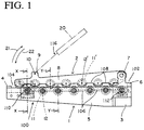
- FIGS. 1 and 2 illustrate an embodiment of a wire decurling apparatus 100 constructed in accordance with the principles of the present invention. It can be seen from these drawings that the apparatus 100 includes a lower wire-straightening frame assembly 1 and an upper wire-straightening frame assembly 2 which is pivoted to the lower frame 1 at a pair of brackets 6 which are located near the exit 102 of the apparatus 100.
- the lower frame assembly 1 is generally rectangular in shape and includes a base plate 3, a pair of brackets 6 fixed to the base plate 3 near the exit 102 of the lower frame assembly 1 and a pair of opposing side members 5 extending therefrom.
- the upper frame assembly 2 of the apparatus 100 is journaled for rotation in the brackets 6 by way of a pivot pin 7 extending between the brackets 6.
- the upper frame assembly 2 also includes a pair of opposing side members 8 which receive the lower member pivot pin 7 therebetween and which are further connected together by way of a lifting rod 10 which extends between two forward lugs 9 of the upper frame assembly 2 located near the entrance 104 of the apparatus 100.
- the upper frame assembly 2 is capable of rotation about the pivot pin 7 to rise away from and close upon the underlying lower frame assembly 1.
- a plurality of wire rolls, or rollers, 11, 11' are provided within the lower assembly frame 1 and the upper assembly frame 2, respectively.
- the lower frame 1 assembly is illustrated as having seven lower axles 12 fixed at regular intervals between its opposing side members 5.
- Each such axle 12 includes a plurality of rollers 11 rotatably mounted thereon by way associated bearings 13. (FIG. 5.)
- These axles 12 are spaced apart in a horizontal spacing so that an intervening space 106 is formed between adjacent rollers 11.
- the axles 12 are further mounted at equal elevations so that a generally level bed, or first set, of rollers 11 is defined in the lower frame assembly 1.
- the upper frame assembly 2 has seven similar upper axles 12' fixed at regular intervals between its opposing side members 8 and each axle 12' includes a plurality of wire-rollers 11' rotatably mounted thereon by way associated bearings 13'. These rollers 11' are also spaced apart from each other with intervening spaces 108 to define a bed, or second set, of wire rollers 11' in the upper frame assembly 2.
- each roller 11, 11' of the upper frame assembly 2 have a spacing which is equal to that of rollers 11 of lower frame assembly 1 but offset from the lower frame assembly 1 in that the upper rollers 11' are shifted longitudinally one half the distance between rollers 11 so that they are interposed between the rollers 11 of the lower frame assembly 1.
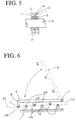
- each roller 11, 11' preferably has a circumferential groove 14 formed therein, which permits a wire to be inserted and held therein in order to decurl it. As shown in FIG. 5, the groove 14 is deep enough so as to provide significant lateral support to the wires in order to retain the wires within the rollers.
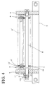
- an actuating member 15 extends lengthwise along one side of the lower frame 1 and is connected to another piston-cylinder type of drive unit 18.
- the actuating member 15 is mounted by way of a pin 17 at the base plate 3 of the lower frame 1 so that it is capable of pivotal movement in the direction indicated by arrow 19.
- This actuating member 15 is operatively connected to all of the axles 12 of the wire rollers of the lower frame assembly 1 except the axle adjacent base plate 3 by way of pins 16. This connection is shown best in FIG. 4.
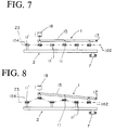
- FIG. 7 schematically illustrates the apparatus in a condition prior to this lateral displacement
- FIG. 8 schematically illustrates the apparatus after the lateral displacement has taken place. This displacement is divergent along the length of the apparatus and the amount of this transverse, or lateral displacement, is greatest near the entrance 104 of the apparatus 100 and gradually decreases toward the exit 102.
- the upper frame assembly 2 has a drive unit 20 associated therewith, which includes, as illustrated in FIG. 1, a piston-cylinder assembly 116 which engages the front lifting rod 10, thereby pivoting the upper frame assembly 2 about pivot pin 7 in the directions as indicated by arrows 21 and 22. Specifically, when the upper frame assembly 2 pivots upwardly about pivot pin 7 in the direction as indicated by arrow 21, it rises away from the underlying lower frame assembly 1 so that its rollers 11' move away from the rollers 11 of the lower frame assembly 1.
- wires 23 are decurled or straightened by utilization of the apparatus 100 in these drawings.
- the wires 23 are shown in phantom and are representative of wires which are fed off of wire supply spools for assembly and termination into wire harnesses or other components.
- the wires 23 enter the entrance 104 of the apparatus at a wire retainer 4 (FIG. 1) and exit from the apparatus at the exit 102 adjacent stationary plate 3.
- These wires 23 may be initially fed into the apparatus 100 through the wire retainer 4 when the upper frame assembly 2 is pivoted upwardly to the position indicated by arrow 21 to expose the rollers 11 of the lower frame 1.
- the wires 23 are then fed into the grooves 14 of the lower frame rollers 11 along the length of the apparatus 100 from the entrance 104 at the wire holder 4 to the exit 102 at plate 3.
- the lateral actuating rod 15 is initially positioned at its retracted position as shown in FIG. 7, wherein it extends parallel to and along the longitudinal side 8 of the lower frame assembly 1 in order to facilitate the feeding of the wires 23 through apparatus 100. In this initial position, rollers 11, 11' are in linear alignment.
- the upper frame assembly 2 After feeding the wires 23 through the lower frame assembly 1, the upper frame assembly 2 is pivoted downwardly, as indicated by arrow 22, until it rests on the underlying lower frame 1 with the rollers 11, 11' of each frame assembly overlapping each other vertically and with the wires 23 extending through rollers 11, 11'.
- the actuating rod 15 is then laterally displaced from the longitudinal side of the stationary frame 1 by pivoting the actuating rod 15 around its pivot pin with the aid of the piston-and-cylinder drive unit 18.
- the wires 23 can then be driven through the apparatus 100 from the entrance 104 to the exit 102 thereof in the ordinary course of manufacturing harnesses in order to decurl or straighten the wires.
- the wires 23 are simultaneously subjected to both vertical alternating displacement or bending (illustrated in phantom in FIG. 6) and lateral or horizontal alternating displacement or bending (illustrated in phantom in FIG. 8) as the wires 23 pass through the apparatus 100.
- the amount of vertical and lateral displacement decreases gradually in the direction of wire travel, namely from the entrance 104 to the exit 102 of the apparatus 100. This causes the wires 23 to be subjected to bending such that the curl of the wires 23 is gradually reduced little by little until a complete decurling is attained at the exit 102 of the wire straightening apparatus 100.
- the number of the bending increments depends on the number of axles 12, 12' which may be varied to meet the amount of decurling necessary. Therefore, the particular number of axles in the embodiment described above should not be considered as limiting.
- the number of the rollers 11, 11' at each axle will generally correspond to the number of circuits of the electrical connectors to which wires are to be connected.
Landscapes
- Engineering & Computer Science (AREA)
- Manufacturing & Machinery (AREA)
- Mechanical Engineering (AREA)
- Electric Cable Installation (AREA)
- Wire Processing (AREA)
Abstract
A wire decurling apparatus (100) occupies a minimum of space and has two interconnected subassemblies (1, 2) which are hinged together so that the upper subassembly (2) may pivot with respect to the lower subassembly (1). Each subassembly (1, 2) has a plurality of rollers (11, 11') arranged therein which are shifted in two directions with respect to each other, thus subjecting the wires to both to vertical and lateral bending simultaneously while passing through the apparatus (100).
Description
- The present invention generally relates to an apparatus for reshaping the configuration of electrical wires, and more particularly to removing curls from electrical wires after they have been unwound from supply spools.
- When electrical wires are connected to electrical connectors, such as what occurs in the manufacture of wire harnesses, the wires are typically unrolled from supply spools of wire. These wires are measured as they are unrolled and often acquire a "curl" from being stored in a wound condition of the supply spool as well as during the measuring process, thus resulting in a significant amount of residual curl.
- The feeding of these wires to a termination assembly usually occurs in a straightline path, and if the wires have any residual curl as they come off of the supply spools, this curl may affect the efficiency and reliability of the terminating assembly at which location the wires are terminated to electrical connectors. Thus, it becomes necessary to "decurl" these wires in order to facilitate the handling and termination of the wires to their associated connector elements.
- Wire decurling apparatuses are known which use two sets of opposing rollers in which wires are arranged to travel between them, such as that shown in Japanese Utility Model application No. 6-9087. These decurling apparatuses are often referred to as wire straighteners or wire reshapers. In the wire decurling apparatus in the aforementioned Utility Model application, the rollers of one set are shifted to lie between the rollers of the other set such that the rollers of the one group extend between two rollers of the other group in adjacent steps so that the rollers of these two opposing groups overlap each other vertically. This overlapping decreases in the direction of travel of the wires.
- With a view to attaining the complete decurling of wires, two individual wire straighteners are arranged in series, namely, one after another, in the direction in which the wires travel so that the wires are forced to uncurl in both the longitudinal and lateral directions. These forces effect a straightening of the wires. However, in this type of decurling apparatus, the threading of the wires through the opposing rollers of the wire straighteners in series is a tedious and time-consuming task. Apart from the tedium, another disadvantage of such a decurling apparatus is that the wire straighteners as arranged in series occupy a relatively large space.
- One object of the present invention is to provide a decurling apparatus and method for decurling wires in which the registering of wires in the apparatus is facilitated.
- Another object of the present invention is to provide a wire decurling apparatus which facilitates the registration of wires, and which does not require a large amount of space for installation.
- A still further object of the present invention is to provide a decurling apparatus having two interengaging decurling roller assemblies which apply displacements in both the longitudinal and lateral directions to wires entering the apparatus.
- These objects and advantages may be attained by providing a wire decurling apparatus having a plurality of opposing wire rollers which bend wires passing through the apparatus simultaneously in two different, intersecting directions.
- A method of decurling wires by causing the curled wires to zigzag between two groups of opposing wire rollers arranged so as to form a plurality of force-application points, is improved according to the present invention in that it comprises the steps of: interposing a first set of spaced-apart wire rollers between a individual wire rollers of a second adjacent set of wire rollers that the opposing rollers of the two sets vertically overlap each other and displacing one group of rollers transversely or horizontally with respect to the other group of rollers.
- In such a method, the horizontal, transverse displacement and the overlapping vertical displacement of the rollers is arranged to decrease from the entrance to the exit of the apparatus in the direction in which the wires travel through the apparatus. A plurality of electric wires which pass through the apparatus encounter a corresponding plurality of wire rollers arranged at each application point, thereby uncurling such a plurality of electric wires simultaneously.
- With the arrangement described above, a single wire decurling apparatus is provided which permits the simultaneous bending of wires in two directions in a reduced space. The registering of the wires is made simpler by raising the moveable frame assembly apart from the stationary frame assembly, thus opening the apparatus wide enough to facilitate the registering of the wires in place therein.
- These and other objects, features and advantages of the present invention will be clearly understood through a consideration of the following detailed description.
- In the course of the following description of the detailed description, reference will be made to the attached drawings wherein like reference numerals identify like parts and wherein:
- FIG. 1 is a side elevational view of a wire decurling apparatus constructed in accordance with the principles of the present invention;
- FIG. 2 is a top plan view of the wire decurling apparatus of FIG. 1;
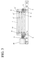
- FIG. 3 is a sectional view of the wire decurling apparatus of FIG. 1 taken generally along line X-X thereof;
- FIG. 4 is a sectional view of the wire decurling apparatus of FIG. 1 taken generally along line Y-Y thereof;
- FIG. 5 is a sectional view of a mounting end of one of the rollers of the decurling apparatus of FIG. 1;
- FIG. 6 is a schematic view illustrating how the upper wire-straightening frame moves in relation to the lower wire-straightening frame;
- FIG. 7 is a schematic view illustrating the lower wire-straightening frame prior to any horizontal displacement of any rollers therein; and
- FIG. 8 is a schematic view illustrating the lower wire-straightening frame after horizontal displacement of selected rollers thereof.
- FIGS. 1 and 2 illustrate an embodiment of a
wire decurling apparatus 100 constructed in accordance with the principles of the present invention. It can be seen from these drawings that theapparatus 100 includes a lower wire-straighteningframe assembly 1 and an upper wire-straighteningframe assembly 2 which is pivoted to thelower frame 1 at a pair ofbrackets 6 which are located near theexit 102 of theapparatus 100. - The
lower frame assembly 1 is generally rectangular in shape and includes abase plate 3, a pair ofbrackets 6 fixed to thebase plate 3 near theexit 102 of thelower frame assembly 1 and a pair ofopposing side members 5 extending therefrom. Theupper frame assembly 2 of theapparatus 100 is journaled for rotation in thebrackets 6 by way of apivot pin 7 extending between thebrackets 6. Theupper frame assembly 2 also includes a pair ofopposing side members 8 which receive the lowermember pivot pin 7 therebetween and which are further connected together by way of alifting rod 10 which extends between twoforward lugs 9 of theupper frame assembly 2 located near theentrance 104 of theapparatus 100. Theupper frame assembly 2 is capable of rotation about thepivot pin 7 to rise away from and close upon the underlyinglower frame assembly 1. - A plurality of wire rolls, or rollers, 11, 11' are provided within the
lower assembly frame 1 and theupper assembly frame 2, respectively. Specifically, thelower frame 1 assembly is illustrated as having sevenlower axles 12 fixed at regular intervals between itsopposing side members 5. Eachsuch axle 12 includes a plurality ofrollers 11 rotatably mounted thereon by way associatedbearings 13. (FIG. 5.) Theseaxles 12 are spaced apart in a horizontal spacing so that anintervening space 106 is formed betweenadjacent rollers 11. Preferably, theaxles 12 are further mounted at equal elevations so that a generally level bed, or first set, ofrollers 11 is defined in thelower frame assembly 1. Likewise, theupper frame assembly 2 has seven similar upper axles 12' fixed at regular intervals between itsopposing side members 8 and each axle 12' includes a plurality of wire-rollers 11' rotatably mounted thereon by way associated bearings 13'. These rollers 11' are also spaced apart from each other with interveningspaces 108 to define a bed, or second set, of wire rollers 11' in theupper frame assembly 2. - It should be noted that the rollers 11' of the
upper frame assembly 2 have a spacing which is equal to that ofrollers 11 oflower frame assembly 1 but offset from thelower frame assembly 1 in that the upper rollers 11' are shifted longitudinally one half the distance betweenrollers 11 so that they are interposed between therollers 11 of thelower frame assembly 1. As seen from FIG. 5, eachroller 11, 11' preferably has acircumferential groove 14 formed therein, which permits a wire to be inserted and held therein in order to decurl it. As shown in FIG. 5, thegroove 14 is deep enough so as to provide significant lateral support to the wires in order to retain the wires within the rollers. - As seen in FIG. 2, an actuating
member 15 extends lengthwise along one side of thelower frame 1 and is connected to another piston-cylinder type ofdrive unit 18. The actuatingmember 15 is mounted by way of apin 17 at thebase plate 3 of thelower frame 1 so that it is capable of pivotal movement in the direction indicated byarrow 19. This actuatingmember 15 is operatively connected to all of theaxles 12 of the wire rollers of thelower frame assembly 1 except the axleadjacent base plate 3 by way ofpins 16. This connection is shown best in FIG. 4. - In this regard, the
ends 114 of thelower axles 11 extend through one side member 5 (shown at the left in FIGS. 3 & 4) in order to effect the connection to the actuatingmember 15. When the actuatingmember 15 is pivoted aboutpin 17, it causes a lateral displacement in the horizontal plane of thelower axles 11 and theirrollers 12. FIG. 7 schematically illustrates the apparatus in a condition prior to this lateral displacement, while FIG. 8 schematically illustrates the apparatus after the lateral displacement has taken place. This displacement is divergent along the length of the apparatus and the amount of this transverse, or lateral displacement, is greatest near theentrance 104 of theapparatus 100 and gradually decreases toward theexit 102. - The
upper frame assembly 2 has adrive unit 20 associated therewith, which includes, as illustrated in FIG. 1, a piston-cylinder assembly 116 which engages thefront lifting rod 10, thereby pivoting theupper frame assembly 2 aboutpivot pin 7 in the directions as indicated byarrows upper frame assembly 2 pivots upwardly aboutpivot pin 7 in the direction as indicated byarrow 21, it rises away from the underlyinglower frame assembly 1 so that its rollers 11' move away from therollers 11 of thelower frame assembly 1. When theupper frame assembly 2 rotates in the opposite counter direction, toward thelower frame assembly 1 as indicated byarrow 22, it comes to rest on thelower frame assembly 1 with the upper frame rollers 11' overlapping therollers 11 of thelower frame assembly 1 and descending into the opposing interveningopen spaces 106 of thelower frame assembly 1 so that they are interposed between therollers 11 of thefirst frame assembly 1. As seen in FIG. 6, this "overlap" decreases gradually from theentrance 104 of theapparatus 100 towards theexit 102. For example, it can be seen that the lower surface of thegroove 14 of the upper roller 11' closest to theentrance 104 is substantially below the upper surface of thegroove 14 of the adjacentlower roller 11 closest toentrance 104. On the other hand, the lower surface of thegroove 14 of the upper roller 11' closest to exit 102 is close to the same level as the upper surface of thegroove 14 of the adjacentlower roller 11 closest to exit 102. - Referring to FIGS. 6, 7 and 8, the manner in which
wires 23 are decurled or straightened by utilization of theapparatus 100 is described below. In these drawings, thewires 23 are shown in phantom and are representative of wires which are fed off of wire supply spools for assembly and termination into wire harnesses or other components. Thewires 23 enter theentrance 104 of the apparatus at a wire retainer 4 (FIG. 1) and exit from the apparatus at theexit 102 adjacentstationary plate 3. Thesewires 23 may be initially fed into theapparatus 100 through thewire retainer 4 when theupper frame assembly 2 is pivoted upwardly to the position indicated byarrow 21 to expose therollers 11 of thelower frame 1. Thewires 23 are then fed into thegrooves 14 of thelower frame rollers 11 along the length of theapparatus 100 from theentrance 104 at thewire holder 4 to theexit 102 atplate 3. Thelateral actuating rod 15 is initially positioned at its retracted position as shown in FIG. 7, wherein it extends parallel to and along thelongitudinal side 8 of thelower frame assembly 1 in order to facilitate the feeding of thewires 23 throughapparatus 100. In this initial position,rollers 11, 11' are in linear alignment. - After feeding the
wires 23 through thelower frame assembly 1, theupper frame assembly 2 is pivoted downwardly, as indicated byarrow 22, until it rests on the underlyinglower frame 1 with therollers 11, 11' of each frame assembly overlapping each other vertically and with thewires 23 extending throughrollers 11, 11'. The actuatingrod 15 is then laterally displaced from the longitudinal side of thestationary frame 1 by pivoting the actuatingrod 15 around its pivot pin with the aid of the piston-and-cylinder drive unit 18. Thewires 23 can then be driven through theapparatus 100 from theentrance 104 to theexit 102 thereof in the ordinary course of manufacturing harnesses in order to decurl or straighten the wires. - Owing to the vertical overlapping and horizontal, lateral displacement of the
rollers 11 of the lower andupper frame assemblies wires 23 are simultaneously subjected to both vertical alternating displacement or bending (illustrated in phantom in FIG. 6) and lateral or horizontal alternating displacement or bending (illustrated in phantom in FIG. 8) as thewires 23 pass through theapparatus 100. The amount of vertical and lateral displacement decreases gradually in the direction of wire travel, namely from theentrance 104 to theexit 102 of theapparatus 100. This causes thewires 23 to be subjected to bending such that the curl of thewires 23 is gradually reduced little by little until a complete decurling is attained at theexit 102 of thewire straightening apparatus 100. - The number of the bending increments depends on the number of
axles 12, 12' which may be varied to meet the amount of decurling necessary. Therefore, the particular number of axles in the embodiment described above should not be considered as limiting. The number of therollers 11, 11' at each axle will generally correspond to the number of circuits of the electrical connectors to which wires are to be connected. - It will be appreciated that the embodiments of the present invention discussed herein are merely illustrative of a few applications of the principles of the invention. Numerous modifications may be made by those skilled in the art without departing from the true spirit and scope of the invention.
Claims (15)
- An apparatus (100) for removing curl from a plurality of electrical wires (23) after unwinding of the wires from a coiled wire supply in order to straighten said wires (23) prior to termination of said wires to an electrical component, said wires being passed through the apparatus (100) prior to termination, said apparatus (100) comprising:a plurality of first and second subassembly pairs (1,2), each first subassembly being operatively connected to a second subassembly, said apparatus having opposing entrance (104) and exit (102) portions;each first subassembly (1) having a plurality of first wire-engaging rollers (11), each of the first rollers (11) having at least one exterior working surface (14) disposed thereon for contacting a wire (23) fed into said apparatus (100), the first rollers (11) being generally arranged in a first set within said first subassembly (1), said first rollers (11) being spaced apart longitudinally between said entrance and exit portions so as to define first intervening open spaces (106) between adjacent first rollers (11);each second subassembly (2) having a plurality of second wire-engaging rollers (11'), each of the second rollers (11') also having at least one exterior working surface (14') disposed thereon for contacting a wire (23) fed into said apparatus (100), the second rollers (11') being generally arranged in a second set within said second subassembly (2), said second rollers (11') being spaced apart longitudinally between said entrance and exit portions so as to define second intervening open spaces (108) between adjacent second rollers (11');one of said first rollers being aligned with each said second intervening open spaces and one of said second rollers being aligned with each of said first intervening open spaces;said first and second rollers of each said first and second subassembly pairs cooperating to define a wire feeding path, the working surfaces of said first rollers being on a first side of said wire feeding path and the working surfaces of said second rollers being on a second, opposite side of said wire feeding path;the working surfaces of at least some of said first and second rollers of each said first and second subassembly pairs being offset in first and second generally perpendicular directions, said at least some of said first and second rollers being offset predetermined distances from a straight line extending between said entrance and exit portions, the distances between said working surfaces and said straight line decreasing along said apparatus from said entrance portion to said exit portion.
- The decurling apparatus as defined in claim 1, wherein said first rollers of each first subassembly generally lie in a first common plane extending lengthwise of said first subassembly (1), and said second rollers of each second subassembly generally lie in a second common plane extending lengthwise of said second subassembly, said first and second common planes being non-parallel.
- The decurling apparatus as defined in claim 1, wherein said first and second roller working surfaces (14,14') include outer circumferential grooves, said grooves being dimensioned so as to provide substantial lateral support to said wires.
- The decurling apparatus as defined in claim 3, wherein said grooves have a greater depth than width in order to provide such lateral support.
- The decurling apparatus as defined in claim 1, wherein said predetermined directions are horizontal and vertical.
- The decurling apparatus as defined in claim 1, further comprising a plurality of first and second axles (12,12'), a first roller of each first subassembly being located on each of said first axles and wherein said a second roller of each second subassembly being located on each of said second axles.
- The decurling apparatus as defined in claim 6, wherein said first axles are interconnected by an elongated first frame member (5) and said second axles are interconnected by an elongated second frame member (8).
- The decurling apparatus as defined in claim 1, further comprising selected first roller moving means (18) operatively associated with an elongated first actuating member (15) extending lengthwise along a path between said entrance and exit portions, said first roller moving means and said actuating member (15) being operative to move selected ones of said first rollers laterally in said first direction.
- The decurling apparatus as defined in claim 8, further comprising second roller moving means (20) operatively associated with said second frame member (8), said second frame member extending lengthwise along a path between said entrance and exit portions, said second roller moving means being operative to move second frame member and selected ones of said second rollers in said second direction.
- The decurling apparatus as defined in claim 8, wherein said first actuating member (15) is pivotally connected to said apparatus about a first pivot point near said exit portion (102) thereof, whereby upon actuating said selected first roller moving means (18), said first actuating member (15) pivots about said first pivot point and contacts selected end portions of said first rollers (114) to thereby create a divergent lateral displacement with respect to said wires (23) passing through said apparatus (100) and across said first and second rollers (11,11').
- The decurling apparatus as defined in claim 10, wherein said divergent lateral displacement is greatest at said entrance portion (104) of said apparatus (100).
- The decurling apparatus as defined in claim 10, wherein said divergent lateral displacement is greatest at said entrance portion (104) of said apparatus and is least at said exit portion (102) of said apparatus (100).
- A method of threading electrical wires through a decurling apparatus for subsequently feeding the wires through bi-directional displacement, comprising the steps of:providing a plurality of rollers (11,11') spaced apart from each and disposed in opposing first and second sets of rollers, each of the first and second rollers having a wire-engagement surface (14,14') disposed thereon;feeding a plurality of wires along said wire engagement surfaces of one of said sets of rollers;drawing said first and second roller sets (11,11') together such that rollers (11) of said first roller set are interposed between the rollers (11') of said second roller set and rollers of said second roller set are interposed between said rollers (11) of said first set, said wire engagement surfaces of the other of said sets of rollers engaging said wires, said wires (23) following said wire-engagement surfaces (14,14') of said first and second rollers in opposing vertical directions; anddisplacing one of said first and second roller sets transversely with respect to the other of said first and second roller sets to thereby displace wires (23) following said wire-engagement surfaces (14,14') of said first and second rollers (11,11') in opposing horizontal directions.
- The method of claim 13, wherein said displacements in said vertical and horizontal opposing directions are divergent lengthwise through said first and second rollers (11, 11').
- The method of claim 14, wherein said plurality of rollers are mounted within an apparatus (100) with defined entrance (104) and exit (102) portions, and said displacements in said vertical and horizontal opposing directions diverge between said entrance (104) and exit (102) portions of said apparatus (100), said displacements being greatest at said entrance portion (104) and being least at said exit portion (102).
Applications Claiming Priority (2)
| Application Number | Priority Date | Filing Date | Title |
|---|---|---|---|
| JP11911195A JP2932158B2 (en) | 1995-04-20 | 1995-04-20 | Wire habit removing method and device |
| JP119111/95 | 1995-04-20 |
Publications (2)
| Publication Number | Publication Date |
|---|---|
| EP0739066A2 true EP0739066A2 (en) | 1996-10-23 |
| EP0739066A3 EP0739066A3 (en) | 1997-07-23 |
Family
ID=14753195
Family Applications (1)
| Application Number | Title | Priority Date | Filing Date |
|---|---|---|---|
| EP96106110A Withdrawn EP0739066A3 (en) | 1995-04-20 | 1996-04-18 | Apparatus for uncurling electric wires and method for using same |
Country Status (2)
| Country | Link |
|---|---|
| EP (1) | EP0739066A3 (en) |
| JP (1) | JP2932158B2 (en) |
Cited By (5)
| Publication number | Priority date | Publication date | Assignee | Title |
|---|---|---|---|---|
| EP1559487A1 (en) * | 2004-02-02 | 2005-08-03 | UNIMAC S.r.l. | Method and apparatus for straightening one or more wires |
| EP2399856A1 (en) | 2010-06-23 | 2011-12-28 | Komax Holding AG | Aligning device for aligning cables and corresponding method |
| CN106654807A (en) * | 2016-12-30 | 2017-05-10 | 国网山东省电力公司高密市供电公司 | Cable core neatening device |
| WO2020089677A1 (en) * | 2018-10-31 | 2020-05-07 | Schleuniger Holding Ag | Aligning device for a wire processing machine and method for operating an aligning system |
| WO2024076546A1 (en) * | 2022-10-02 | 2024-04-11 | Ppc Broadband, Inc. | Handheld tool for straightening a fiber cable that is structurally configured to enhance placement of the fiber cable in a straightening path of the tool |
Families Citing this family (1)
| Publication number | Priority date | Publication date | Assignee | Title |
|---|---|---|---|---|
| JP5853578B2 (en) * | 2011-10-20 | 2016-02-09 | 住友電装株式会社 | Electric wire straightening device |
Citations (5)
| Publication number | Priority date | Publication date | Assignee | Title |
|---|---|---|---|---|
| DE529198C (en) * | 1928-06-27 | 1931-07-09 | Adam Kirvel | Straighteners for wires, tubular wires, etc. like |
| US1914975A (en) * | 1931-11-27 | 1933-06-20 | Sleeper & Hartley Inc | Wire straightening device |
| FR2138615A1 (en) * | 1971-05-27 | 1973-01-05 | Kieserling & Albrecht | |
| US3979937A (en) * | 1975-04-07 | 1976-09-14 | Jury Lukich Semenenko | Paired-roll straightening machine |
| US4949567A (en) * | 1988-11-04 | 1990-08-21 | Corbin Edward W | Apparatus and method for control of wire cast and helix |
-
1995
- 1995-04-20 JP JP11911195A patent/JP2932158B2/en not_active Expired - Lifetime
-
1996
- 1996-04-18 EP EP96106110A patent/EP0739066A3/en not_active Withdrawn
Patent Citations (5)
| Publication number | Priority date | Publication date | Assignee | Title |
|---|---|---|---|---|
| DE529198C (en) * | 1928-06-27 | 1931-07-09 | Adam Kirvel | Straighteners for wires, tubular wires, etc. like |
| US1914975A (en) * | 1931-11-27 | 1933-06-20 | Sleeper & Hartley Inc | Wire straightening device |
| FR2138615A1 (en) * | 1971-05-27 | 1973-01-05 | Kieserling & Albrecht | |
| US3979937A (en) * | 1975-04-07 | 1976-09-14 | Jury Lukich Semenenko | Paired-roll straightening machine |
| US4949567A (en) * | 1988-11-04 | 1990-08-21 | Corbin Edward W | Apparatus and method for control of wire cast and helix |
Cited By (10)
| Publication number | Priority date | Publication date | Assignee | Title |
|---|---|---|---|---|
| EP1559487A1 (en) * | 2004-02-02 | 2005-08-03 | UNIMAC S.r.l. | Method and apparatus for straightening one or more wires |
| EP2399856A1 (en) | 2010-06-23 | 2011-12-28 | Komax Holding AG | Aligning device for aligning cables and corresponding method |
| CN102366803A (en) * | 2010-06-23 | 2012-03-07 | 科马斯控股股份公司 | Aligning device for aligning cables and corresponding method |
| US8978435B2 (en) | 2010-06-23 | 2015-03-17 | Komax Holding Ag | Wire straightening apparatus |
| CN102366803B (en) * | 2010-06-23 | 2015-09-02 | 科马斯控股股份公司 | For aligning the straightener of cable and corresponding method |
| CN106654807A (en) * | 2016-12-30 | 2017-05-10 | 国网山东省电力公司高密市供电公司 | Cable core neatening device |
| CN106654807B (en) * | 2016-12-30 | 2022-07-29 | 国网山东省电力公司高密市供电公司 | Cable core wire arranging device |
| WO2020089677A1 (en) * | 2018-10-31 | 2020-05-07 | Schleuniger Holding Ag | Aligning device for a wire processing machine and method for operating an aligning system |
| CN112912187A (en) * | 2018-10-31 | 2021-06-04 | 施洛伊尼格股份公司 | Straightening device for a cable processing machine and method for operating a straightening mechanism |
| WO2024076546A1 (en) * | 2022-10-02 | 2024-04-11 | Ppc Broadband, Inc. | Handheld tool for straightening a fiber cable that is structurally configured to enhance placement of the fiber cable in a straightening path of the tool |
Also Published As
| Publication number | Publication date |
|---|---|
| JP2932158B2 (en) | 1999-08-09 |
| JPH08294210A (en) | 1996-11-05 |
| EP0739066A3 (en) | 1997-07-23 |
Similar Documents
| Publication | Publication Date | Title |
|---|---|---|
| US5230147A (en) | Electrical hardness termination apparatus and method | |
| US5142105A (en) | Electrical cable and method for manufacturing the same | |
| EP0739066A2 (en) | Apparatus for uncurling electric wires and method for using same | |
| US3996783A (en) | Method and apparatus for reforming round ducts into rectangular ducts | |
| US4976294A (en) | Method and apparatus for making specified-length wires for wire harness | |
| EP0813271A2 (en) | Wire end alignment assembly for wire crimping apparatus | |
| WO2020089677A1 (en) | Aligning device for a wire processing machine and method for operating an aligning system | |
| US5732457A (en) | Electrical wire harness binding apparatus | |
| US4204417A (en) | Apparatus and method for winding electrical coils | |
| EP0181780A2 (en) | Wire preparation system | |
| JP3166067B2 (en) | Harness manufacturing method and wire pressure welding apparatus | |
| JPS6135665B2 (en) | ||
| JPH05304747A (en) | Device for continuously winding band-shaped wire material and its control method | |
| JPH0680113U (en) | Wire length measuring device that prevents curling of wires | |
| US2793672A (en) | Method of close coiling sheathed spring wire | |
| US6260267B1 (en) | Manufacture of a wire harness | |
| US5673475A (en) | Wire-length measuring apparatus | |
| CA2412678C (en) | Assembly line method for and method of producing armature coils | |
| AU691685B2 (en) | Methods and apparatus for manufacturing helical products | |
| JP3341610B2 (en) | Correction method of irregular cross section | |
| JPS6021855Y2 (en) | Tape wire manufacturing equipment | |
| JPH0261334B2 (en) | ||
| US4578978A (en) | Roll forming apparatus | |
| JPH0366790B2 (en) | ||
| JP6720442B2 (en) | Pressure welding method, pressure welding device |
Legal Events
| Date | Code | Title | Description |
|---|---|---|---|
| PUAI | Public reference made under article 153(3) epc to a published international application that has entered the european phase |
Free format text: ORIGINAL CODE: 0009012 |
|
| AK | Designated contracting states |
Kind code of ref document: A2 Designated state(s): DE FR GB IT |
|
| PUAL | Search report despatched |
Free format text: ORIGINAL CODE: 0009013 |
|
| AK | Designated contracting states |
Kind code of ref document: A3 Designated state(s): DE FR GB IT |
|
| 17P | Request for examination filed |
Effective date: 19980107 |
|
| STAA | Information on the status of an ep patent application or granted ep patent |
Free format text: STATUS: THE APPLICATION IS DEEMED TO BE WITHDRAWN |
|
| 18D | Application deemed to be withdrawn |
Effective date: 19991103 |