EP0719600A1 - A rolling unit for rolling rod-shaped or tubular bodies - Google Patents
A rolling unit for rolling rod-shaped or tubular bodies Download PDFInfo
- Publication number
- EP0719600A1 EP0719600A1 EP95203118A EP95203118A EP0719600A1 EP 0719600 A1 EP0719600 A1 EP 0719600A1 EP 95203118 A EP95203118 A EP 95203118A EP 95203118 A EP95203118 A EP 95203118A EP 0719600 A1 EP0719600 A1 EP 0719600A1
- Authority
- EP
- European Patent Office
- Prior art keywords
- rolling
- rolls
- unit
- axis
- roll
- Prior art date
- Legal status (The legal status is an assumption and is not a legal conclusion. Google has not performed a legal analysis and makes no representation as to the accuracy of the status listed.)
- Granted
Links
- 238000005096 rolling process Methods 0.000 title claims abstract description 116
- 239000000969 carrier Substances 0.000 claims description 3
- 238000000034 method Methods 0.000 abstract description 2
- 230000010355 oscillation Effects 0.000 abstract description 2
- 230000008569 process Effects 0.000 abstract description 2
- 230000008901 benefit Effects 0.000 description 6
- 238000010276 construction Methods 0.000 description 3
- XEEYBQQBJWHFJM-UHFFFAOYSA-N Iron Chemical compound [Fe] XEEYBQQBJWHFJM-UHFFFAOYSA-N 0.000 description 2
- 238000012423 maintenance Methods 0.000 description 2
- 238000004519 manufacturing process Methods 0.000 description 2
- 229910000831 Steel Inorganic materials 0.000 description 1
- 230000009471 action Effects 0.000 description 1
- 230000004075 alteration Effects 0.000 description 1
- 238000012937 correction Methods 0.000 description 1
- 230000003247 decreasing effect Effects 0.000 description 1
- 238000013461 design Methods 0.000 description 1
- 238000006073 displacement reaction Methods 0.000 description 1
- 230000000694 effects Effects 0.000 description 1
- 229910052742 iron Inorganic materials 0.000 description 1
- 238000012986 modification Methods 0.000 description 1
- 230000004048 modification Effects 0.000 description 1
- 230000003534 oscillatory effect Effects 0.000 description 1
- 238000012545 processing Methods 0.000 description 1
- 230000000284 resting effect Effects 0.000 description 1
- 239000011265 semifinished product Substances 0.000 description 1
- 239000010959 steel Substances 0.000 description 1
- 238000011144 upstream manufacturing Methods 0.000 description 1
Images


Classifications
-
- B—PERFORMING OPERATIONS; TRANSPORTING
- B21—MECHANICAL METAL-WORKING WITHOUT ESSENTIALLY REMOVING MATERIAL; PUNCHING METAL
- B21B—ROLLING OF METAL
- B21B1/00—Metal-rolling methods or mills for making semi-finished products of solid or profiled cross-section; Sequence of operations in milling trains; Layout of rolling-mill plant, e.g. grouping of stands; Succession of passes or of sectional pass alternations
- B21B1/16—Metal-rolling methods or mills for making semi-finished products of solid or profiled cross-section; Sequence of operations in milling trains; Layout of rolling-mill plant, e.g. grouping of stands; Succession of passes or of sectional pass alternations for rolling wire rods, bars, merchant bars, rounds wire or material of like small cross-section
- B21B1/18—Metal-rolling methods or mills for making semi-finished products of solid or profiled cross-section; Sequence of operations in milling trains; Layout of rolling-mill plant, e.g. grouping of stands; Succession of passes or of sectional pass alternations for rolling wire rods, bars, merchant bars, rounds wire or material of like small cross-section in a continuous process
-
- B—PERFORMING OPERATIONS; TRANSPORTING
- B21—MECHANICAL METAL-WORKING WITHOUT ESSENTIALLY REMOVING MATERIAL; PUNCHING METAL
- B21B—ROLLING OF METAL
- B21B13/00—Metal-rolling stands, i.e. an assembly composed of a stand frame, rolls, and accessories
- B21B13/08—Metal-rolling stands, i.e. an assembly composed of a stand frame, rolls, and accessories with differently-directed roll axes, e.g. for the so-called "universal" rolling process
- B21B13/10—Metal-rolling stands, i.e. an assembly composed of a stand frame, rolls, and accessories with differently-directed roll axes, e.g. for the so-called "universal" rolling process all axes being arranged in one plane
- B21B13/103—Metal-rolling stands, i.e. an assembly composed of a stand frame, rolls, and accessories with differently-directed roll axes, e.g. for the so-called "universal" rolling process all axes being arranged in one plane for rolling bars, rods or wire
-
- B—PERFORMING OPERATIONS; TRANSPORTING
- B21—MECHANICAL METAL-WORKING WITHOUT ESSENTIALLY REMOVING MATERIAL; PUNCHING METAL
- B21B—ROLLING OF METAL
- B21B17/00—Tube-rolling by rollers of which the axes are arranged essentially perpendicular to the axis of the work, e.g. "axial" tube-rolling
- B21B17/02—Tube-rolling by rollers of which the axes are arranged essentially perpendicular to the axis of the work, e.g. "axial" tube-rolling with mandrel, i.e. the mandrel rod contacts the rolled tube over the rod length
- B21B17/04—Tube-rolling by rollers of which the axes are arranged essentially perpendicular to the axis of the work, e.g. "axial" tube-rolling with mandrel, i.e. the mandrel rod contacts the rolled tube over the rod length in a continuous process
-
- B—PERFORMING OPERATIONS; TRANSPORTING
- B21—MECHANICAL METAL-WORKING WITHOUT ESSENTIALLY REMOVING MATERIAL; PUNCHING METAL
- B21B—ROLLING OF METAL
- B21B17/00—Tube-rolling by rollers of which the axes are arranged essentially perpendicular to the axis of the work, e.g. "axial" tube-rolling
- B21B17/14—Tube-rolling by rollers of which the axes are arranged essentially perpendicular to the axis of the work, e.g. "axial" tube-rolling without mandrel, e.g. stretch-reducing mills
Definitions
- This invention relates to a rolling unit for rolling generic rod-shaped or tubular bodies, comprising an outer structure, at least three rolls journalled on respective swinging arms and whose rotation axis are substantially perpendicular to a rolling axis along which the unit is laid.
- Rolling units as outlined above are already known in the iron, steel and other related industries for rolling tubular or rod-shaped bodies, the latter definition encompassing any finished and semi-finished products which have a major longitudinal dimension with respect to the others, such as pipes, bars, generic hollow sections, wires, etc..
- the latter can be pulled out of the structure, respectively in an axial or radial direction relative to the rolling axis, so that the rolls can be replaced by moving out the carrier.
- the structure is provided with linear guides for the removal of the carrier which are laid axially or radially, according to the type of the unit structure, and with means for releasably locking the holders in their working position during the rolling process.
- the working rolls are carried on respective swinging arms hinged on the carrier, which extend inwardly of the latter toward the rolling axis.
- the rotation axes of the rolls lie in a plane perpendicular to the rolling axis which is also the plane in which the swing arms oscillate to allow the spacing of the rolls from the rolling axis to be adjusted.
- the construction of the disclosed rolling unit allows the use of three or more driven rolls affording significant advantages in terms of processing quality, while retaining a high degree of flexibility throughout the production process by providing the possibility of independently setting the rolls position with respect to the rolling axis, even during operation. Furthermore, also the rolls replacement is made simpler to carry out, as is the rolling unit overall maintenance.
- the rolls of those rolling units have a shaped outer surface whose intersection with a plane radial to the rolls describes a substantially circular arc, commonly referred to as throat, having substantially the same length as the portion to be rolled of the workpiece, which length is inversely proportional to the number of rolls: that is, in the instance of a three-roll unit, approximately equal to 1/3 of the outer circumference of the workpiece to be rolled, likewise in the instance of a four-roll unit equal to 1/4 and so on.
- the former devices allow for the adjustment to be made also during the rolling process, but cannot apply corrections exceeding a certain limit.
- the profile of the roll throat will move to a position different from the nominal one, which is not symmetrical about the plane P above containing the rolling axis.
- a rolling mill according to the invention, which is of the type described in Italian Patent Applications MI92A000917 and MI93A000704 filed by this Applicant and presently laid open. Accordingly, only a general description of this rolling mill will be given herein, with special regard to those elements which distinguish it from what is specified in the above documents, while for further details, reference shall be made to the content of the specifications of the cited applications, hereto incorporated.
- the rolling mill 1 comprises an outer structure 2 being laid along a rolling axis L and resting on a base B.
- the structure 2 of the rolling mill comprises a plurality of rigidly interconnected members 2a which are parts of respective structures S, joined continuously to one another, of rolling units 5 aligned along the rolling axis L to form the rolling mill 1.
- Each rolling unit 5 includes two members 2a laid side-by-side in the primary structure 2 of the rolling mill, the members 2a forming its outer structure S which accommodates an enclosing roll carrier 10 on its interior consisting, in this example, of a hexagonal frame.
- the carrier 10 is supported slidably along the rolling axis L on a pair of guides 12 disposed within the structure S; it can be locked into an operative position inside the structure S and slid to a non-operative position outside the latter.
- the carriers are packed into the structure 2, being borne on the guides 12 which extend lengthwise of the structure, and means, not shown in the drawings, are provided for the purpose of retaining them in that arrangement.
- rollers 20 Mounted in the carrier 10 are three rolls 20, journalled on respective chocks 21, adapted to be driven rotatively about respective coplanar axes A1, A2 and A3 which lie in a perpendicular plane to the rolling axis L, by means of corresponding extensions 23 to be attached to respective connection shafts 25 of the rolls.
- the rolling unit 5 and the rolling mill 1 include, of course, drive means M for driving the extensions 23.
- the chocks 21, in turn, are mounted on respective swinging arms 30 which are allowed to oscillate about a respective trunnion 31 located on the holder 10.
- Each swinging arm will pivot in a radial plane to the rolling axis L, that is in a perpendicular plane to the rotation axis A1, A2 or A3 of the corresponding roll which contains the rolling axis L.
- each roll in the unit there is also a device 35 for adjusting the position of the roll relative to the rolling axis; such adjustment devices comprise a fixed part 35a rigidly connected to the members 2a, and a moving part 35b which reciprocates along a radial direction to the rolling axis and acts on the roll chocks 21.
- a contrast means 38 effective to hold the rolls in an open position, that is away from the rolling axis, even when they are not acting on a workpiece to be rolled, to counteract the weight of each of them; in this example, this means consists of oil-operated cylinders.
- the roll carrier are staggered along the rolling axis L of the rolling mill such that the sliding directions of the moving portions of the adjustment devices for each roll are, in the instance of a rolling unit having three rolls, rotated 60° from one rolling unit to the next, and in general rotated through an angle of 180°/n, where n is the number of rolls per rolling unit.
- the rolling of rod-shaped or tubular body is carried out on a rolling mill according to the invention, this takes place gradually and accurately on account of at least the three driven rolls being provided for each rolling unit, with the other advantages that characterize rolling mills equipped with three or more driven rolls.
- the rod-shaped or tubular workpiece will be inserted directly or after being fitted over a mandrel, not shown in the drawings, from a feed-in end of the rolling mill and entrained to a feed-out end of the mill by the action of the rolls in the various rolling units.
- the setting of the rolls in each rolling unit can be adjusted to accommodate variations in the shape of their throats, as may result from the periodical re-turning of the rolls.
- the pins on which the arms are hinged will require no positional adjustment on the carrier because it is sufficient that the arm of each roll be rotated to set the roll to a proper distance for repositioning the roll throat relative to the rolling axis.
- the contrast means can be used to advantage for setting the rolls to their desired positions.
- a rolling unit according to the invention can offer a number of advantages.
- the layout of the swinging arms in radial planes to the rolling axis generally prevents the insurgence of roll asymmetries during the releasing and clamping movements from/to a workpiece or as a result of an increased or decreased distance of the roll rotation axis from the rolling axis; also, with the arms arranged as provided by the invention, it becomes possible to increase their radial shack on the pins to facilitate the assembly and disassembly of the swinging arm for the maintenance of the roll carrier.
- FIG. 5 a rolling unit is shown which has an outer structure S of the open type, that is one formed of members 2a which are generally C-shaped rather than being annular as in the previously discussed example.
- This embodiment also includes guides 12 along which the roll carrier 10 can be slid between an operative position where it is locked within the structure and a non-operative position for its removal.
- those structural members which, as shown in Figure 5, have the same functions in this modified embodiment as in the previous example, have been denoted by the same numerals.
- the layout of the swinging arms in radial planes to the rolling axis yields the same advantageous results as the previous example.
- the swinging arms could be arranged to oscillate about a respective pin mounted on a carrier extractable from an outer structure, and adjustment devices could be associated with each roll and provided with a moving part active on the arm and a fixed part mounted to the structure, as previously described.
- rolling units may also be used to advantage with rolling mills wherein the rotation axes of the driven or freely rotatable roll pairs are staggered 90° from one unit to the next.
Abstract
Description
- This invention relates to a rolling unit for rolling generic rod-shaped or tubular bodies, comprising an outer structure, at least three rolls journalled on respective swinging arms and whose rotation axis are substantially perpendicular to a rolling axis along which the unit is laid.
- Rolling units as outlined above are already known in the iron, steel and other related industries for rolling tubular or rod-shaped bodies, the latter definition encompassing any finished and semi-finished products which have a major longitudinal dimension with respect to the others, such as pipes, bars, generic hollow sections, wires, etc..
- Two recent examples of rolling units of this type, as well as of rolling mills incorporating them, are described in Italian Patent Applications MI92A000917 and MI93A000704 filed by this Applicant and presently laid open. In particular, these documents disclose a unit having a primary outer structure wherein a roll carrier of framed construction is mounted.
- Advantageously, the latter can be pulled out of the structure, respectively in an axial or radial direction relative to the rolling axis,
so that the rolls can be replaced by moving out the carrier. To this aim, the structure is provided with linear guides for the removal of the carrier which are laid axially or radially, according to the type of the unit structure, and with means for releasably locking the holders in their working position during the rolling process. - The working rolls are carried on respective swinging arms hinged on the carrier, which extend inwardly of the latter toward the rolling axis. The rotation axes of the rolls lie in a plane perpendicular to the rolling axis which is also the plane in which the swing arms oscillate to allow the spacing of the rolls from the rolling axis to be adjusted.
- As explained in the above Italian Applications, the construction of the disclosed rolling unit allows the use of three or more driven rolls affording significant advantages in terms of processing quality, while retaining a high degree of flexibility throughout the production process by providing the possibility of independently setting the rolls position with respect to the rolling axis, even during operation. Furthermore, also the rolls replacement is made simpler to carry out, as is the rolling unit overall maintenance.
- In accordance with the current trend to improve performances of such rolling units in order to expand their applicability, a demand exists for a solution to a problem which actually affects their operability and is connected with the prior art arrangements for mounting the rolls on the swinging arms.
- In fact, the rolls of those rolling units have a shaped outer surface whose intersection with a plane radial to the rolls describes a substantially circular arc, commonly referred to as throat, having substantially the same length as the portion to be rolled of the workpiece, which length is inversely proportional to the number of rolls: that is, in the instance of a three-roll unit, approximately equal to 1/3 of the outer circumference of the workpiece to be rolled, likewise in the instance of a four-roll unit equal to 1/4 and so on.
- During operation of a rolling mill employing rolling units like those described above, possible uncontrolled thermal lengthwise expansions of the arms due to the high temperatures at which the process is sometimes carried out, cause movements of the rolls of a rolling unit from their nominal setting.
- In this case, the positive results of this solution are partly reduced. Current rolling units are equipped with special adjustment devices arranged to act on the swinging arms which carry the rolls and to absorb the radial rolling forces; provision is also made for adjusting the position of the pins on which the arms are hinged.
- The former devices allow for the adjustment to be made also during the rolling process, but cannot apply corrections exceeding a certain limit.
- In fact, their operation produces a rotation of the arm about its pin (see Figure 1); this rotation causes the roll to be moved from its nominal working conditions, that is a condition wherein of a median plane P of the roll perpendicular to the rotation axis thereof, passes through the rolling axis L (in Figure 1, the intersection track of this plane with that of the drawing is vertical and is illustrated by a dot and dash line).
- Consequently to this displacement, the profile of the roll throat will move to a position different from the nominal one, which is not symmetrical about the plane P above containing the rolling axis.
- While for small oscillations of the swinging arms this may not be a problem, this effect must be compensated where adjustments on a wider range are involved.
- This is done in practice by adjusting the position of the pins of the arm of each roll (see, for example, the direction of the arrow in Figure 1), so that it is evident how the pin position setting has to be carried out each time, for instance, that the rolls are re-turned.
- It is the invention object to provide a rolling unit having such constructional and operational features as to allow the rolls to be set in position without incurring the problems with which the aforementioned prior art is concerned.
- This object is achieved, according to the invention, by a rolling unit as indicated in the preamble having the characterizing features set forth in the appended claims.
- Further features and the advantages of the invention will more clearly result by an embodiment thereof described herein below by way of example and not of limitation with reference to the accompanying drawings, in which:
- Figure 1 is, as already referred to, a detail view of a prior art rolling unit;
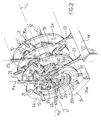
- Figure 2 is a perspective view of a rolling mill incorporating rolling units according to the invention;
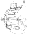
- Figure 3 is a part-sectional front view of a unit according to the invention;
- Figure 4 is a sectional side view of the rolling mill of Figure 2, taken along the line IV-IV in Figure 3;
- Figure 5 is a part-sectional front view of an alternative embodiment of the rolling unit shown in Figure 3.
- Referring to Figures 2 to 4, generally shown at 1 is a rolling mill according to the invention, which is of the type described in Italian Patent Applications MI92A000917 and MI93A000704 filed by this Applicant and presently laid open. Accordingly, only a general description of this rolling mill will be given herein, with special regard to those elements which distinguish it from what is specified in the above documents, while for further details, reference shall be made to the content of the specifications of the cited applications, hereto incorporated.
- The rolling mill 1 comprises an
outer structure 2 being laid along a rolling axis L and resting on a base B. Thestructure 2 of the rolling mill comprises a plurality of rigidly interconnectedmembers 2a which are parts of respective structures S, joined continuously to one another, of rolling units 5 aligned along the rolling axis L to form the rolling mill 1. - Each rolling unit 5 includes two
members 2a laid side-by-side in theprimary structure 2 of the rolling mill, themembers 2a forming its outer structure S which accommodates an enclosingroll carrier 10 on its interior consisting, in this example, of a hexagonal frame. - Specifically, the
carrier 10 is supported slidably along the rolling axis L on a pair ofguides 12 disposed within the structure S; it can be locked into an operative position inside the structure S and slid to a non-operative position outside the latter. - In the rolling mill, the carriers are packed into the
structure 2, being borne on theguides 12 which extend lengthwise of the structure, and means, not shown in the drawings, are provided for the purpose of retaining them in that arrangement. - Mounted in the
carrier 10 are threerolls 20, journalled onrespective chocks 21, adapted to be driven rotatively about respective coplanar axes A1, A2 and A3 which lie in a perpendicular plane to the rolling axis L, by means ofcorresponding extensions 23 to be attached torespective connection shafts 25 of the rolls. - To this aim, the rolling unit 5 and the rolling mill 1 include, of course, drive means M for driving the
extensions 23. - The
chocks 21, in turn, are mounted on respective swingingarms 30 which are allowed to oscillate about arespective trunnion 31 located on theholder 10. Each swinging arm will pivot in a radial plane to the rolling axis L, that is in a perpendicular plane to the rotation axis A1, A2 or A3 of the corresponding roll which contains the rolling axis L. - Associated with each roll in the unit there is also a
device 35 for adjusting the position of the roll relative to the rolling axis; such adjustment devices comprise afixed part 35a rigidly connected to themembers 2a, and a movingpart 35b which reciprocates along a radial direction to the rolling axis and acts on theroll chocks 21. - These devices are known per se, and may be either oil or electrically operated; in the latter case, the moving and the fixed parts would jointly form a helical pair and therefore, further to the reciprocating motion mentioned above, the former is provided with a rotative motion about the aforementioned radial direction.
- Furthermore, provided at each swinging arm of the rolling unit is a contrast means 38 effective to hold the rolls in an open position, that is away from the rolling axis, even when they are not acting on a workpiece to be rolled, to counteract the weight of each of them; in this example, this means consists of oil-operated cylinders.
- The roll carrier are staggered along the rolling axis L of the rolling mill such that the sliding directions of the moving portions of the adjustment devices for each roll are, in the instance of a rolling unit having three rolls, rotated 60° from one rolling unit to the next, and in general rotated through an angle of 180°/n, where n is the number of rolls per rolling unit.
- As to the way in which the rolling of rod-shaped or tubular body is carried out on a rolling mill according to the invention, this takes place gradually and accurately on account of at least the three driven rolls being provided for each rolling unit, with the other advantages that characterize rolling mills equipped with three or more driven rolls. Thus, the rod-shaped or tubular workpiece will be inserted directly or after being fitted over a mandrel, not shown in the drawings, from a feed-in end of the rolling mill and entrained to a feed-out end of the mill by the action of the rolls in the various rolling units.
- But more important is the fact that the rolling unit of this invention does achieve its previously stated object.
- In fact, it will be recognized from Figure 4 that on the occurrence of longitudinal expansions of the swinging arms of each unit, no geometrical alterations would be induced as may affect the position of a
roll 20 relative to the rolling axis L, because such expansions occur in a radial plane to the rolling axis L. This reflects favorably on production, in that a highly accurate rolling process can be obtained even when operating under conditions of uncontrolled thermal expansion. - Furthermore, it will be appreciated that the setting of the rolls in each rolling unit can be adjusted to accommodate variations in the shape of their throats, as may result from the periodical re-turning of the rolls. In fact, the pins on which the arms are hinged will require no positional adjustment on the carrier because it is sufficient that the arm of each roll be rotated to set the roll to a proper distance for repositioning the roll throat relative to the rolling axis. On this circumstance, the contrast means can be used to advantage for setting the rolls to their desired positions.
- A rolling unit according to the invention can offer a number of advantages.
- For example, the layout of the swinging arms in radial planes to the rolling axis generally prevents the insurgence of roll asymmetries during the releasing and clamping movements from/to a workpiece or as a result of an increased or decreased distance of the roll rotation axis from the rolling axis; also, with the arms arranged as provided by the invention, it becomes possible to increase their radial shack on the pins to facilitate the assembly and disassembly of the swinging arm for the maintenance of the roll carrier.
- Finally, it should be noted that, because of the oscillatory movements of the swinging arms occurring in radial planes, the rotation axis of each roll and the fixed axis located upstream of a drive extension will remain parallel to each other even while the arm is being moved.
- In addition, the possibility should not be ruled out of making changes and modifications to the rolling unit of this invention. One of such possible variations is shown in Figure 5, where a rolling unit is shown which has an outer structure S of the open type, that is one formed of
members 2a which are generally C-shaped rather than being annular as in the previously discussed example. This embodiment also includesguides 12 along which theroll carrier 10 can be slid between an operative position where it is locked within the structure and a non-operative position for its removal. In general, those structural members which, as shown in Figure 5, have the same functions in this modified embodiment as in the previous example, have been denoted by the same numerals. Here again, it will be appreciated that the layout of the swinging arms in radial planes to the rolling axis yields the same advantageous results as the previous example. - Finally, it should be understood that the arrangement of the rolls on the swinging arms in radial planes to the rolling axis could also be applied to rolling units wherein the arms and their rolls are not mounted in special carriers. In other words, this arrangements may be applied to rolling units, and hence rolling mills, other than those provided by the state of the art as previously discussed.
- Lastly, it should be understood that the teaching of this invention may also be applied to rolling units equipped with more than three rolls. For example, it would not be too difficult to design a rolling unit with four rolls, rotatable about respective axes lying on opposite sides and carried by swinging arms which oscillate in respective planes perpendicularly to the rotation axes and containing the rolling axis.
- Also, in this case, to make the construction of the rolling unit less complicated, a configuration could be provided wherein only one pair of opposite rolls be driven, and the other pair left freely rotatable. Here again, the swinging arms could be arranged to oscillate about a respective pin mounted on a carrier extractable from an outer structure, and adjustment devices could be associated with each roll and provided with a moving part active on the arm and a fixed part mounted to the structure, as previously described.
- Finally, it will be appreciated that such rolling units may also be used to advantage with rolling mills wherein the rotation axes of the driven or freely rotatable roll pairs are staggered 90° from one unit to the next.
Claims (10)
- A rolling unit for rod-shaped or tubular bodies, comprising an outer structure (S), at least three rolls (20) journalled on respective swinging arms (30) whose rotation axes (A1,A2,A3) lay substantially perpendicular to a rolling axis (L) along which the unit is laid, characterized in that said swinging arms can be oscillated in respective planes substantially perpendicular to the rotation axes of the corresponding rolls and containing said rolling axis.
- A rolling unit according to Claim 1, characterized in that at least two of said rolls (20) are driven rolls.
- A rolling unit according to either Claim 1 or 2, characterized in that said swinging arms (30) are mounted in a roll carrier (10) which is slidable in a guided manner between an operative position occupied during the rolling process and where it is locked within said structure (S) and a non-operative position outside said structure.
- A rolling unit according to any of the preceding claims, characterized in that said outer structure (S) is substantially cylindrical in shape and coaxial with the rolling axis.
- A rolling unit according to Claim 3, characterized in that said outer structure (S) is substantially C-shaped and open sideways to permit the sliding movement of said roll carrier (10).
- A rolling unit according to any of the preceding claims, characterized in that it comprises an adjustment device (35) associated with each swinging arm (30), which device includes a fixed part (35a) connected to the outer structure (S) of the unit and a moving part (35b) arranged to move along a radial direction to the rolling axis (L) and to act on the corresponding arm.
- A rolling mill for rolling rod-shaped or tubular bodies, characterized in that it comprises a plurality of rolling units as claimed in Claims 1 to 6 laid side-by-side along the rolling axis (L) between a feed-in end and a feed-out end for said rod-shaped or tubular bodies.
- A rolling mill according to Claim 7, characterized in that the outer structures of the side-by-side rolling units are interconnected rigidly to form a primary outer structure (2) of the rolling mill.
- A rolling mill according to either Claim 7 or 8 when depending on Claims 3 to 6, characterized in that the roll carriers (10) of the rolling units are identical with one another, and that the rolls of one unit and those of an adjacent unit in the rolling mill are staggered, the staggered layout being obtained by turning upside-down the carrier about an overturn axis which intersects the rolling axis (L) and extends parallel to one of the roll (20) axes (A1,A2,A3).
- A rolling mill according to Claim 9, characterized in that each roll carrier (10) carries three rolls having respective rotation axes (A1,A2,A3) which intersect one another at an angle of 60° when lying in the same plane.
Applications Claiming Priority (2)
| Application Number | Priority Date | Filing Date | Title |
|---|---|---|---|
| ITMI942661 | 1994-12-28 | ||
| ITMI942661A IT1271808B (en) | 1994-12-28 | 1994-12-28 | LAMINATION UNIT FOR TUBULAR BODIES OR ASTIFORMS IN GENERAL |
Publications (2)
| Publication Number | Publication Date |
|---|---|
| EP0719600A1 true EP0719600A1 (en) | 1996-07-03 |
| EP0719600B1 EP0719600B1 (en) | 1999-10-27 |
Family
ID=11370094
Family Applications (1)
| Application Number | Title | Priority Date | Filing Date |
|---|---|---|---|
| EP95203118A Expired - Lifetime EP0719600B1 (en) | 1994-12-28 | 1995-11-15 | A rolling unit for rolling rod-shaped or tubular bodies |
Country Status (8)
| Country | Link |
|---|---|
| US (1) | US5765423A (en) |
| EP (1) | EP0719600B1 (en) |
| JP (1) | JP3775839B2 (en) |
| KR (1) | KR960023914A (en) |
| CN (1) | CN1068803C (en) |
| AT (1) | ATE185988T1 (en) |
| DE (1) | DE69513002D1 (en) |
| IT (1) | IT1271808B (en) |
Cited By (6)
| Publication number | Priority date | Publication date | Assignee | Title |
|---|---|---|---|---|
| WO1998006515A1 (en) * | 1996-08-13 | 1998-02-19 | Demag Italimpianti S.P.A. | Rolling mill for sizing tubes or cylindrical bodies in general in the iron and steel industry |
| WO2007014911A1 (en) * | 2005-07-29 | 2007-02-08 | Danieli & C. Officine Meccaniche S.P.A. | Rolling mill with stands with three adjustable rolls |
| WO2007144905A1 (en) * | 2006-06-12 | 2007-12-21 | Sms Demag Innse S.P.A. | Retained mandrel rolling mill for seamless tubes |
| WO2010097232A1 (en) * | 2009-02-26 | 2010-09-02 | Kocks Technik Gmbh & Co.Kg | Roll stand, rolling train, and use of said roll stand and/or said rolling train for reducing rods and/or tubes |
| US8341994B2 (en) | 2008-05-22 | 2013-01-01 | Danieli & C. Officine Meccaniche S.P.A. | Rolling mill stand and related rolling mill for longitudinally rolling rod-shaped bodies |
| IT202000028772A1 (en) * | 2020-11-27 | 2022-05-27 | Danieli Off Mecc | CALIBRATING ROLLING MILL AND/OR REDUCER FOR ROD-SHAPED BODIES |
Families Citing this family (11)
| Publication number | Priority date | Publication date | Assignee | Title |
|---|---|---|---|---|
| IT1279085B1 (en) * | 1995-11-29 | 1997-12-04 | Innocenti Eng Spa | UNIT FOR LAMINATION FOR SPINDLE TUBES |
| IT1298750B1 (en) * | 1998-03-18 | 2000-02-02 | Demag Italimpianti Spa | ROLLING MILL WITH OSCILLATING ARMS, INTENDED IN PARTICULAR BUT NOT EXCLUSIVELY FOR THE LAMINATION OF SEAMLESS PIPES |
| CN1270085A (en) * | 1999-01-15 | 2000-10-18 | 张少渊 | Adjustable 4-roller cross rolling mill with single (or dual) ihnput drive axlecs) |
| DE19935647C2 (en) * | 1999-07-29 | 2003-10-09 | Kocks Technik | Process for rolling heated metallic material and plant for carrying out the process |
| DE102007013902A1 (en) * | 2007-03-20 | 2008-09-25 | Universität Dortmund | Device for profile bending |
| BR112013032680B1 (en) | 2011-06-22 | 2021-08-17 | Ashley Dean Olsson | LAMINATOR CHAIR, LAMINATOR AND LAMINATION METHOD |
| ITMI20111391A1 (en) * | 2011-07-26 | 2013-01-27 | Sms Innse Spa | ROLLER CARTRIDGE FOR A MILL |
| ITMI20130590A1 (en) * | 2013-04-11 | 2014-10-12 | Danieli Off Mecc | LAMINATION CAGE WITH THREE ROLLERS WITH SIDE CHANGE |
| CN103302101A (en) * | 2013-07-02 | 2013-09-18 | 中冶赛迪工程技术股份有限公司 | Swinging arm type rolling frame |
| CN103599938B (en) * | 2013-12-03 | 2016-08-17 | 中冶赛迪工程技术股份有限公司 | Four roller continuous pipe rolling mills |
| CN105728469A (en) * | 2016-05-10 | 2016-07-06 | 沈阳重机重矿机械设备制造有限公司 | High-strength rack of Y-shaped rolling mill |
Citations (3)
| Publication number | Priority date | Publication date | Assignee | Title |
|---|---|---|---|---|
| FR2398554A1 (en) * | 1977-07-26 | 1979-02-23 | Ch Polt I | LAMINATOR CAGE |
| EP0264849A2 (en) * | 1986-10-20 | 1988-04-27 | Sms Schloemann-Siemag Aktiengesellschaft | Process and arrangement for rolling profiled bars within small tolerances |
| EP0565772A1 (en) * | 1992-04-15 | 1993-10-20 | INNSE INNOCENTI ENGINEERING S.p.A. | A rolling stand, having three driven and adjustable rollers |
Family Cites Families (2)
| Publication number | Priority date | Publication date | Assignee | Title |
|---|---|---|---|---|
| DE547717C (en) * | 1926-06-04 | 1932-04-01 | E H Gustav Asbeck Dr Ing | Universal rolling mill |
| IT1264032B (en) * | 1993-04-08 | 1996-09-09 | Filippo Cattaneo | Rolling stand for rolling mills in general, with three or more controlled and adjustable rollers |
-
1994
- 1994-12-28 IT ITMI942661A patent/IT1271808B/en active IP Right Grant
-
1995
- 1995-11-15 DE DE69513002T patent/DE69513002D1/en not_active Expired - Lifetime
- 1995-11-15 AT AT95203118T patent/ATE185988T1/en active
- 1995-11-15 EP EP95203118A patent/EP0719600B1/en not_active Expired - Lifetime
- 1995-11-22 US US08/561,537 patent/US5765423A/en not_active Expired - Lifetime
- 1995-12-26 JP JP33904695A patent/JP3775839B2/en not_active Expired - Lifetime
- 1995-12-27 CN CN95120118A patent/CN1068803C/en not_active Expired - Lifetime
- 1995-12-28 KR KR1019950072199A patent/KR960023914A/en not_active Application Discontinuation
Patent Citations (4)
| Publication number | Priority date | Publication date | Assignee | Title |
|---|---|---|---|---|
| FR2398554A1 (en) * | 1977-07-26 | 1979-02-23 | Ch Polt I | LAMINATOR CAGE |
| EP0264849A2 (en) * | 1986-10-20 | 1988-04-27 | Sms Schloemann-Siemag Aktiengesellschaft | Process and arrangement for rolling profiled bars within small tolerances |
| EP0565772A1 (en) * | 1992-04-15 | 1993-10-20 | INNSE INNOCENTI ENGINEERING S.p.A. | A rolling stand, having three driven and adjustable rollers |
| WO1993020960A1 (en) * | 1992-04-15 | 1993-10-28 | Innse Innocenti Engineering S.P.A. | A rolling stand for generic rolling mills having three or more adjustable driven rolls |
Cited By (13)
| Publication number | Priority date | Publication date | Assignee | Title |
|---|---|---|---|---|
| US6116071A (en) * | 1996-08-13 | 2000-09-12 | Demag Italimpianti S.P.A. | Rolling mill for sizing tubes or cylindrical bodies in general in the iron and steel industry |
| WO1998006515A1 (en) * | 1996-08-13 | 1998-02-19 | Demag Italimpianti S.P.A. | Rolling mill for sizing tubes or cylindrical bodies in general in the iron and steel industry |
| US7849723B2 (en) | 2005-07-29 | 2010-12-14 | Danieli & C. Officine Meccaniche S.P.A. | Rolling mill with stands with three adjustable rolls |
| WO2007014911A1 (en) * | 2005-07-29 | 2007-02-08 | Danieli & C. Officine Meccaniche S.P.A. | Rolling mill with stands with three adjustable rolls |
| CN102189106B (en) * | 2005-07-29 | 2012-07-25 | 丹尼利机械设备股份公司 | Rolling mill with stands with three adjustable rolls |
| EA014479B1 (en) * | 2006-06-12 | 2010-12-30 | Смс Демаг Иннсе С.П.А. | Retained mandrel rolling mill for seamless tubes |
| WO2007144905A1 (en) * | 2006-06-12 | 2007-12-21 | Sms Demag Innse S.P.A. | Retained mandrel rolling mill for seamless tubes |
| US8341994B2 (en) | 2008-05-22 | 2013-01-01 | Danieli & C. Officine Meccaniche S.P.A. | Rolling mill stand and related rolling mill for longitudinally rolling rod-shaped bodies |
| US8640516B2 (en) | 2008-05-22 | 2014-02-04 | Danieli & C. Officine Meccanicite S.p.A. | Rolling mill stand and related rolling mill for longitudinally rolling rod-shaped bodies |
| US9180502B2 (en) | 2008-05-22 | 2015-11-10 | Danieli & C. Officine Meccaniche S.P.A. | Rolling mill stand and related rolling mill for longitudinally rolling rod-shaped bodies |
| WO2010097232A1 (en) * | 2009-02-26 | 2010-09-02 | Kocks Technik Gmbh & Co.Kg | Roll stand, rolling train, and use of said roll stand and/or said rolling train for reducing rods and/or tubes |
| IT202000028772A1 (en) * | 2020-11-27 | 2022-05-27 | Danieli Off Mecc | CALIBRATING ROLLING MILL AND/OR REDUCER FOR ROD-SHAPED BODIES |
| WO2022112986A1 (en) * | 2020-11-27 | 2022-06-02 | Danieli & C. Officine Meccaniche S.P.A. | Reducer and/or calibrating rolling mill for rod-shaped bodies |
Also Published As
| Publication number | Publication date |
|---|---|
| JPH08224607A (en) | 1996-09-03 |
| US5765423A (en) | 1998-06-16 |
| JP3775839B2 (en) | 2006-05-17 |
| KR960023914A (en) | 1996-07-20 |
| CN1068803C (en) | 2001-07-25 |
| EP0719600B1 (en) | 1999-10-27 |
| CN1132671A (en) | 1996-10-09 |
| ATE185988T1 (en) | 1999-11-15 |
| DE69513002D1 (en) | 1999-12-02 |
| IT1271808B (en) | 1997-06-09 |
| ITMI942661A1 (en) | 1996-06-28 |
| ITMI942661A0 (en) | 1994-12-28 |
Similar Documents
| Publication | Publication Date | Title |
|---|---|---|
| US5765423A (en) | Rolling unit for rolling rod-shaped or tubular bodies | |
| EP0593709B1 (en) | A rolling stand for generic rolling mills having three or more adjustable driven rolls | |
| EP1048371B1 (en) | Straightener for rolled ferrous products, having horizontally openable shoulders for fast change of the rolls | |
| EP0421575B1 (en) | Adjustable guide for rotating cylindrical member | |
| CN110038921B (en) | Sizing and straightening process for welded steel pipe | |
| US4574606A (en) | Adjusting the rolls in a rolling mill with obliquely oriented, conically contoured rolls | |
| US3543555A (en) | Form changing device for continuous casting | |
| EP0752284B1 (en) | Roll stand with separable roll parting adjustment module | |
| US4494394A (en) | Straightening machines and methods | |
| EP0976468B1 (en) | Roller mount with three-axis freedom | |
| KR19990077563A (en) | Adjustable turndown apparatus | |
| EP0780169B1 (en) | Compact rolling block | |
| US3347078A (en) | Tube reshaping machine | |
| US4198841A (en) | Roll mill stand | |
| US4803861A (en) | Guide structure for pierced hollows | |
| WO1997003771A1 (en) | Electric-resistance welded tube fin pass molding apparatus and double purpose roll apparatus utilizing the same | |
| RU2019333C1 (en) | Machine for bending rolled sheets | |
| US3459022A (en) | Roller-equipped straightening machine | |
| EP1060802B1 (en) | Piercing mill | |
| JP3297994B2 (en) | Punch rolling mill and cannon replacement method | |
| SU1731306A1 (en) | Rolling mill stand group | |
| SU1750781A1 (en) | Roller sheet-metal bending machine | |
| JPH1157813A (en) | Rolling stand element and rolling stand obtained therewith | |
| US6158262A (en) | Piercing mill and cannon exchange method | |
| RU2063283C1 (en) | Roller-bending machine |
Legal Events
| Date | Code | Title | Description |
|---|---|---|---|
| PUAI | Public reference made under article 153(3) epc to a published international application that has entered the european phase |
Free format text: ORIGINAL CODE: 0009012 |
|
| AK | Designated contracting states |
Kind code of ref document: A1 Designated state(s): AT DE ES FR GB IT |
|
| RAP1 | Party data changed (applicant data changed or rights of an application transferred) |
Owner name: INNSE INNOCENTI ENGINEERING SANTEUSTACCHIO S.P.A. |
|
| 17P | Request for examination filed |
Effective date: 19960928 |
|
| 17Q | First examination report despatched |
Effective date: 19980421 |
|
| GRAG | Despatch of communication of intention to grant |
Free format text: ORIGINAL CODE: EPIDOS AGRA |
|
| GRAG | Despatch of communication of intention to grant |
Free format text: ORIGINAL CODE: EPIDOS AGRA |
|
| GRAH | Despatch of communication of intention to grant a patent |
Free format text: ORIGINAL CODE: EPIDOS IGRA |
|
| GRAH | Despatch of communication of intention to grant a patent |
Free format text: ORIGINAL CODE: EPIDOS IGRA |
|
| GRAA | (expected) grant |
Free format text: ORIGINAL CODE: 0009210 |
|
| AK | Designated contracting states |
Kind code of ref document: B1 Designated state(s): AT DE ES FR GB IT |
|
| PG25 | Lapsed in a contracting state [announced via postgrant information from national office to epo] |
Ref country code: ES Free format text: THE PATENT HAS BEEN ANNULLED BY A DECISION OF A NATIONAL AUTHORITY Effective date: 19991027 |
|
| REF | Corresponds to: |
Ref document number: 185988 Country of ref document: AT Date of ref document: 19991115 Kind code of ref document: T |
|
| REF | Corresponds to: |
Ref document number: 69513002 Country of ref document: DE Date of ref document: 19991202 |
|
| PGFP | Annual fee paid to national office [announced via postgrant information from national office to epo] |
Ref country code: AT Payment date: 19991215 Year of fee payment: 5 |
|
| ITF | It: translation for a ep patent filed |
Owner name: JACOBACCI & PERANI S.P.A. |
|
| PG25 | Lapsed in a contracting state [announced via postgrant information from national office to epo] |
Ref country code: GB Free format text: LAPSE BECAUSE OF NON-PAYMENT OF DUE FEES Effective date: 20000127 |
|
| PG25 | Lapsed in a contracting state [announced via postgrant information from national office to epo] |
Ref country code: DE Free format text: LAPSE BECAUSE OF FAILURE TO SUBMIT A TRANSLATION OF THE DESCRIPTION OR TO PAY THE FEE WITHIN THE PRESCRIBED TIME-LIMIT Effective date: 20000128 |
|
| ET | Fr: translation filed | ||
| PLBE | No opposition filed within time limit |
Free format text: ORIGINAL CODE: 0009261 |
|
| STAA | Information on the status of an ep patent application or granted ep patent |
Free format text: STATUS: NO OPPOSITION FILED WITHIN TIME LIMIT |
|
| GBPC | Gb: european patent ceased through non-payment of renewal fee |
Effective date: 20000127 |
|
| 26N | No opposition filed | ||
| PG25 | Lapsed in a contracting state [announced via postgrant information from national office to epo] |
Ref country code: AT Free format text: LAPSE BECAUSE OF NON-PAYMENT OF DUE FEES Effective date: 20001115 |
|
| REG | Reference to a national code |
Ref country code: FR Ref legal event code: TP Ref country code: FR Ref legal event code: CD Ref country code: FR Ref legal event code: CA |
|
| REG | Reference to a national code |
Ref country code: FR Ref legal event code: CD Ref country code: FR Ref legal event code: CA |
|
| PGFP | Annual fee paid to national office [announced via postgrant information from national office to epo] |
Ref country code: FR Payment date: 20141201 Year of fee payment: 20 |
|
| PGFP | Annual fee paid to national office [announced via postgrant information from national office to epo] |
Ref country code: IT Payment date: 20141117 Year of fee payment: 20 |