EP0645125A1 - Intraluminal stent - Google Patents
Intraluminal stent Download PDFInfo
- Publication number
- EP0645125A1 EP0645125A1 EP19940306974 EP94306974A EP0645125A1 EP 0645125 A1 EP0645125 A1 EP 0645125A1 EP 19940306974 EP19940306974 EP 19940306974 EP 94306974 A EP94306974 A EP 94306974A EP 0645125 A1 EP0645125 A1 EP 0645125A1
- Authority
- EP
- European Patent Office
- Prior art keywords
- stent
- bends
- turn
- wire
- turns
- Prior art date
- Legal status (The legal status is an assumption and is not a legal conclusion. Google has not performed a legal analysis and makes no representation as to the accuracy of the status listed.)
- Granted
Links
Images


Classifications
-
- A—HUMAN NECESSITIES
- A61—MEDICAL OR VETERINARY SCIENCE; HYGIENE
- A61M—DEVICES FOR INTRODUCING MEDIA INTO, OR ONTO, THE BODY; DEVICES FOR TRANSDUCING BODY MEDIA OR FOR TAKING MEDIA FROM THE BODY; DEVICES FOR PRODUCING OR ENDING SLEEP OR STUPOR
- A61M29/00—Dilators with or without means for introducing media, e.g. remedies
-
- A—HUMAN NECESSITIES
- A61—MEDICAL OR VETERINARY SCIENCE; HYGIENE
- A61F—FILTERS IMPLANTABLE INTO BLOOD VESSELS; PROSTHESES; DEVICES PROVIDING PATENCY TO, OR PREVENTING COLLAPSING OF, TUBULAR STRUCTURES OF THE BODY, e.g. STENTS; ORTHOPAEDIC, NURSING OR CONTRACEPTIVE DEVICES; FOMENTATION; TREATMENT OR PROTECTION OF EYES OR EARS; BANDAGES, DRESSINGS OR ABSORBENT PADS; FIRST-AID KITS
- A61F2/00—Filters implantable into blood vessels; Prostheses, i.e. artificial substitutes or replacements for parts of the body; Appliances for connecting them with the body; Devices providing patency to, or preventing collapsing of, tubular structures of the body, e.g. stents
- A61F2/82—Devices providing patency to, or preventing collapsing of, tubular structures of the body, e.g. stents
- A61F2/86—Stents in a form characterised by the wire-like elements; Stents in the form characterised by a net-like or mesh-like structure
- A61F2/90—Stents in a form characterised by the wire-like elements; Stents in the form characterised by a net-like or mesh-like structure characterised by a net-like or mesh-like structure
-
- A—HUMAN NECESSITIES
- A61—MEDICAL OR VETERINARY SCIENCE; HYGIENE
- A61F—FILTERS IMPLANTABLE INTO BLOOD VESSELS; PROSTHESES; DEVICES PROVIDING PATENCY TO, OR PREVENTING COLLAPSING OF, TUBULAR STRUCTURES OF THE BODY, e.g. STENTS; ORTHOPAEDIC, NURSING OR CONTRACEPTIVE DEVICES; FOMENTATION; TREATMENT OR PROTECTION OF EYES OR EARS; BANDAGES, DRESSINGS OR ABSORBENT PADS; FIRST-AID KITS
- A61F2/00—Filters implantable into blood vessels; Prostheses, i.e. artificial substitutes or replacements for parts of the body; Appliances for connecting them with the body; Devices providing patency to, or preventing collapsing of, tubular structures of the body, e.g. stents
- A61F2/02—Prostheses implantable into the body
- A61F2/04—Hollow or tubular parts of organs, e.g. bladders, tracheae, bronchi or bile ducts
- A61F2/06—Blood vessels
- A61F2/07—Stent-grafts
- A61F2002/075—Stent-grafts the stent being loosely attached to the graft material, e.g. by stitching
-
- A—HUMAN NECESSITIES
- A61—MEDICAL OR VETERINARY SCIENCE; HYGIENE
- A61F—FILTERS IMPLANTABLE INTO BLOOD VESSELS; PROSTHESES; DEVICES PROVIDING PATENCY TO, OR PREVENTING COLLAPSING OF, TUBULAR STRUCTURES OF THE BODY, e.g. STENTS; ORTHOPAEDIC, NURSING OR CONTRACEPTIVE DEVICES; FOMENTATION; TREATMENT OR PROTECTION OF EYES OR EARS; BANDAGES, DRESSINGS OR ABSORBENT PADS; FIRST-AID KITS
- A61F2230/00—Geometry of prostheses classified in groups A61F2/00 - A61F2/26 or A61F2/82 or A61F9/00 or A61F11/00 or subgroups thereof
- A61F2230/0002—Two-dimensional shapes, e.g. cross-sections
- A61F2230/0028—Shapes in the form of latin or greek characters
- A61F2230/0054—V-shaped
Definitions
- the present invention relates to a stent and, more particularly, to a self-expandable stent for expanding the lumens of a blood vessel or liver in cases where these are constricted.
- a device is required for expanding a constricted passageway of a blood vessel or the liver, or maintaining an open passageway through a vessel portion.
- Such situations arise, for example, when the blood does not flow smoothly or the passageways of the vessel portion are constricted due to arteriosclerosis or the growth of a tumor.
- the elastic body is called a stent, which is, for example, a wire formed in a closed zigzag configuration, joined by a plurality of bends and wound cylindrically, as disclosed in EP 0177330.
- Each section of the stent of the above structure is formed by a plurality of connecting members which link sections to each other for practical use.
- a space is formed between a bend of a first stent section and a corresponding bend of a second stent section. This space allows restenosis of passageways or ducts in the body.
- U.S. Patent No. 4,733,665 discloses a graft which is formed by a tubular shaped member having first and second ends and a wall disposed between the first and second ends.
- the wall surface is formed by a plurality of intersecting elongate members, at least some of which intersect with one another intermediate the first and second ends of the tubular shaped member.
- the elasticity of the graft is formed only in the first and second ends of the tubular shaped member and it is weak therebetween.
- Another object of the present invention is to provide a stent which maintains its length in case of constriction or expansion thereof.
- a further object of the present invention is to provide a stent having a uniform elasticity.
- a stent comprising: a single length of wire bent into a zigzag configuration by forming alternating peaks and valleys, the zigzag configuration being spirally wrapped about an axis into a plurality of turns, the axis forming a longitudinal axis of the stent, and wherein peaks of one turn of the stent are interlocked with valleys of an adjacent turn of the stent.
- the wire has first and second end portions, each of which is bent towards and extends towards a central turn of the stent and is woven in and out of turns of the stent.
- the distal ends of the first and second end portions may be hooked around a portion of a turn.
- a stent for expanding a constricted passageway comprising a length of wire formed into a cylindrical configuration having a plurality of turns of a zigzag configuration consisting of a series of first and second straight sections joined by a plurality of bends consisting of lower and upper bends, wherein each of the first and second straight sections is defined between each of the upper and lower bends, the first straight section being longer than the second straight section and the upper bends of one turn being hooked with corresponding lower bends of an adjacent turn, and wherein the stent is resiliently compressible into a smaller first shape in which all of the straight sections are arranged side by side and closely adjacent one another for insertion into a passageway with the bends having a stress therein, the stent being resiliently expandable by release of said stress into a second shape in which all of the straight sections define a generally circular or cylindrical configuration for pressing against a wall of the passageway.
- the present invention provides a stent formed of one wire member which has a zigzag configuration which is then spiralled into turns, bends of the zigzag being cross-linked with each other at adjacent turns, and ends of the wire preferably being bent and woven between turns.
- the tips of the wire may be hooked around an intermediate turn.
- the first bend 1 is hooked around a first pin 3 on a jig 6, the left portion of the wire 8 is hung inside a second pin 4, and the right portion of the wire 8 is hung on a third pin 5, as shown in Figure 1B.
- the distance between the first and second pins 3 and 4 is longer than that between the first and third pins 3 and 5.
- the second and third pins 4 and 5 are different from the first pin 3, in that the second and third pins 4 and 5 are bent horizontally and have an inner space in which to insert the wire.
- the wire 8 is inserted into the space formed by the bent pin 4 and the wire 8 is bent around the second pin 4 to form a second bend 2 which is referred to as an upper bend. Then, the wire 8 is twisted to a predetermined angle so that the wire 8 can form a desired shape.
- a first straight section 7 is defined as the portion of the wire 8 between the first and second bends 1 and 2, as shown in Figure 1C.
- second bend 2 is hung on the third pin 5 and the portion of the wire to the left of the second bend 2 is bent about first pin 3 to form a third bend 11 and a second straight section 17, as shown in Figure 1D.
- the third bend 11 belongs to the category of lower bends.
- first straight section 7 is formed between the first and second pins 3 and 4 and the second straight section 17 is formed between the first and third pins 3 and 5, the first straight section 7 is longer than the second straight section 17. Further, the first straight section 7 is twisted from the second straight section 17 by a predetermined angle because of the second and third pins 4 and 5, the shapes of which are not important, but which help to form a twisted angle between the first and second straight sections 7 and 17.
- a number of bends is selected for a first turn of the zigzag structure of Figure 1E and the upper bends of such a turn are cross-linked with the corresponding lower bends of the next turn, as shown in Figure 2.
- the wire 8 has a plurality of spiral bends, thereby forming a cylindrical elastic body, as shown in Figure 3.
- the 18th bend 82 which is one of the upper bends 2, 12, 22, 32, 42, 52, 62, 72, 82, 92, 102, «, is cross-linked (or hooked) with the first bend 1.
- the 20th bend 92 which is also one of the upper bends, is cross-linked or hooked with a corresponding bend from the prior turn, namely the third bend 11, which is one of the lower bends.
- the 22nd bend 102 is stuck into the 5th bend 21 from inside to outside, and the 24th bend 112 is stuck into the 7th bend 31.
- the next turn, or a third turn is formed in the same way as the first and second turns. That is, each of the upper bends of the third turn is cross-linked with a corresponding lower bend of the second turn.
- each of the straight sections is preferably about 0.9 cm and the first straight sections 7 are slightly longer than the second straight sections 17.
- the length and the diameter of the stent are determined in accordance with the characteristics of the wire and the lumen where the stent is to be applied.
- Ends 9 and 10 of the wire 8 are disposed at a top position and at a bottom position of the stent, respectively.
- the upper end 9 of the wire 8 extends diagonally in the direction of the bottom of the stent in such a manner that it weaves in and out of every turn or every third turn of the stent from inner side to outer side and from outer side to inner side of each turn.
- the upper end 9 is fixed by being wound around a straight section of a certain turn.
- the lower end 10 extends in the direction of the first turn and is wound around a straight section of a certain turn in a similar manner as the upper end 9. This configuration of the end portions 9 and 10 restrains the deformation of the stent in every direction thereof. It is of no consequence which end is defined as an upper end or lower end.
- bends are arranged spirally and bends are hooked with each other like a chain link fence or net, and both ends are formed in the way described above. Therefore, the bends of the stent do not project outside the whole structure even in the case where the stent is bent due to the linking of the turns to themselves, which means that the passageway where the stent is applied maintains its opening and allows the blood to flow well.
- the interlinking of adjacent bends from each of the various turns serves to regulate and limit expansion and contraction of the stent. Further, the interlinking distributes force evenly and the elasticity of the stent is more uniform than that of prior stents. Still further, deformation in the longitudinal direction is limited by the ends being anchored (bent around) and woven through the different turns of the stent.
- the stent obtained by the above process may have a larger diameter than is practical, it may be necessary to put it into a sleeve of desirable diameter and to treat it with heat.
- the stent may have to be wrapped in a mesh 13, and upper and lower hems of the mesh folded towards the inside of the stent, and both hems respectively adhered or fixed to themselves through the stent's circumference or to the wire.
- the mesh is such that it is not exposed.
- the mesh 13 is made of nylon and the entire mesh has a coating 14 made of silicon rubber.
- the coating 14 is formed as a hose-type membrane which is fitted around the stent and adhered to it.
- the coating 14 can be formed directly around the wire 8, but to increase the adhesive force, the mesh 13 is preferably wrapped around the wire 8 inside of coating 14.
- the effect of the coating is already known in this field, namely to prevent the growth of any tissue or to prevent restenosis.
- the stent of this configuration is implanted in a blood vessel or other body cavity by means of an introducer or by implantation, as will be described below.
- the introducer comprises an inner tube D and a guide G.
- the inner tube D helps the whole introducer to pass through the body cavity smoothly.
- the introducer with the inner tube D inserted in the guide G, and with a stent c located between the guide G and the inner tube D, is inserted into the body cavity to a targeted position.
- the inner tube D is pulled out from the guide G, and the stent C, in its compressed shape, is pushed towards the opening of the guide G, at the desired position, by a pusher H.
- the guide G is pulled out of the body cavity and the stent C alone remains in the body cavity.
- the stent C subsequently expands and presses against a wall of the body cavity in order to maintain an open passageway.
- the stricture of a lumen due to the growth of the tissue can be prevented.
- the stent according to the present invention does not permit penetration of tissue of the lumen. Additionally, the stent has a greater elastic force than prior stents.
- the stent of the present invention does not change longitudinally even when the stent experiences compression or expansion. This means that the stent does not change its position when the stent is placed in a desired position within a body cavity. Thus, once the stent is positioned exactly, there will be no deleterious expansion, contraction or movement thereof.
Abstract
Description
- The present invention relates to a stent and, more particularly, to a self-expandable stent for expanding the lumens of a blood vessel or liver in cases where these are constricted.
- In many situations, a device is required for expanding a constricted passageway of a blood vessel or the liver, or maintaining an open passageway through a vessel portion. Such situations arise, for example, when the blood does not flow smoothly or the passageways of the vessel portion are constricted due to arteriosclerosis or the growth of a tumor.
- It is necessary to expand the passageway for smooth blood flow in such cases, and, for this purpose, devices are proposed and used for pushing a self-expandable elastic body into the constricted passageway. The elastic body is called a stent, which is, for example, a wire formed in a closed zigzag configuration, joined by a plurality of bends and wound cylindrically, as disclosed in EP 0177330.
- Each section of the stent of the above structure is formed by a plurality of connecting members which link sections to each other for practical use. Thus, when the stent is placed in a bent portion of the lumen, a space is formed between a bend of a first stent section and a corresponding bend of a second stent section. This space allows restenosis of passageways or ducts in the body.
- To avoid the use of numerous connecting members, U.S. Patent No. 4,733,665 discloses a graft which is formed by a tubular shaped member having first and second ends and a wall disposed between the first and second ends. The wall surface is formed by a plurality of intersecting elongate members, at least some of which intersect with one another intermediate the first and second ends of the tubular shaped member. In a graft of this configuration, since a plurality of elongate members intersect only with one another, the elasticity of the graft is formed only in the first and second ends of the tubular shaped member and it is weak therebetween.
- Accordingly, it is an object of the present invention to provide a stent which can form a passageway for blood in its bent state yet prevent tissue from penetrating it.
- Another object of the present invention is to provide a stent which maintains its length in case of constriction or expansion thereof.
- A further object of the present invention is to provide a stent having a uniform elasticity.
- According to the present invention, there is provided a stent comprising: a single length of wire bent into a zigzag configuration by forming alternating peaks and valleys, the zigzag configuration being spirally wrapped about an axis into a plurality of turns, the axis forming a longitudinal axis of the stent, and wherein peaks of one turn of the stent are interlocked with valleys of an adjacent turn of the stent.
- Preferably, the wire has first and second end portions, each of which is bent towards and extends towards a central turn of the stent and is woven in and out of turns of the stent.
- The distal ends of the first and second end portions may be hooked around a portion of a turn.
- According to the present invention, there is also provided a stent for expanding a constricted passageway comprising a length of wire formed into a cylindrical configuration having a plurality of turns of a zigzag configuration consisting of a series of first and second straight sections joined by a plurality of bends consisting of lower and upper bends, wherein each of the first and second straight sections is defined between each of the upper and lower bends, the first straight section being longer than the second straight section and the upper bends of one turn being hooked with corresponding lower bends of an adjacent turn, and wherein the stent is resiliently compressible into a smaller first shape in which all of the straight sections are arranged side by side and closely adjacent one another for insertion into a passageway with the bends having a stress therein, the stent being resiliently expandable by release of said stress into a second shape in which all of the straight sections define a generally circular or cylindrical configuration for pressing against a wall of the passageway.
- Thus, the present invention provides a stent formed of one wire member which has a zigzag configuration which is then spiralled into turns, bends of the zigzag being cross-linked with each other at adjacent turns, and ends of the wire preferably being bent and woven between turns. The tips of the wire may be hooked around an intermediate turn.
- Embodiments of the present invention will now be described, by way of example only, with reference to the accompanying drawings, in which:
- Figures 1A to 1E show several stages in the manufacture of a stent for expanding lumens;
- Figure 2 shows a further stage in the manufacture of the stent;
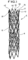
- Figure 3 is a perspective view of the stent;
- Figures 4A to 4D show steps for implantation of the stent into a lumen of a blood vessel or liver; and
- Figure 5 is a perspective view of another embodiment in which the stent is wrapped in a mesh and coated with silicon rubber.
- Referring to Figure 1A, a
wire 8 having upper andlower ends upper end portion 9 to form afirst bend 1 which is referred to as a lower bend. Thefirst bend 1 is hooked around afirst pin 3 on a jig 6, the left portion of thewire 8 is hung inside asecond pin 4, and the right portion of thewire 8 is hung on athird pin 5, as shown in Figure 1B. - The distance between the first and
second pins third pins third pins first pin 3, in that the second andthird pins wire 8 is inserted into the space formed by thebent pin 4 and thewire 8 is bent around thesecond pin 4 to form asecond bend 2 which is referred to as an upper bend. Then, thewire 8 is twisted to a predetermined angle so that thewire 8 can form a desired shape. - A first straight section 7 is defined as the portion of the
wire 8 between the first andsecond bends - Subsequently,
second bend 2 is hung on thethird pin 5 and the portion of the wire to the left of thesecond bend 2 is bent aboutfirst pin 3 to form athird bend 11 and a secondstraight section 17, as shown in Figure 1D. Thethird bend 11 belongs to the category of lower bends. - Since the first straight section 7 is formed between the first and
second pins straight section 17 is formed between the first andthird pins straight section 17. Further, the first straight section 7 is twisted from the secondstraight section 17 by a predetermined angle because of the second andthird pins straight sections 7 and 17. - If such a process is continued, as illustrated in Figure 1E, a wire of a zigzag configuration, which has a plurality of first and second
straight sections 7 and 17,lower bends upper bends end portions wire 8 are left unbent. - A number of bends is selected for a first turn of the zigzag structure of Figure 1E and the upper bends of such a turn are cross-linked with the corresponding lower bends of the next turn, as shown in Figure 2. Eventually, the
wire 8 has a plurality of spiral bends, thereby forming a cylindrical elastic body, as shown in Figure 3. - Referring to Figure 2, if the number of bends for a turn is 18, the
18th bend 82, which is one of theupper bends first bend 1. The20th bend 92, which is also one of the upper bends, is cross-linked or hooked with a corresponding bend from the prior turn, namely thethird bend 11, which is one of the lower bends. The22nd bend 102 is stuck into the5th bend 21 from inside to outside, and the24th bend 112 is stuck into the7th bend 31. The next turn, or a third turn, is formed in the same way as the first and second turns. That is, each of the upper bends of the third turn is cross-linked with a corresponding lower bend of the second turn. - Such a process is continued until a desired height of the stent, or a desired number of turns, is obtained. Then, the upper bends (2nd, 4th, 6th,8th, ..., and 18th bends) are arranged spirally, the lower bends (the 1st, 3rd, 5th, 7th ..., and 17th bends) are also arranged spirally, and the cylindrical body is obtained as shown in Figure 3.
- It is desirable to make the stent about 10 cm long. Each of the straight sections is preferably about 0.9 cm and the first straight sections 7 are slightly longer than the second
straight sections 17. However, the length and the diameter of the stent are determined in accordance with the characteristics of the wire and the lumen where the stent is to be applied. - Ends 9 and 10 of the
wire 8 are disposed at a top position and at a bottom position of the stent, respectively. Theupper end 9 of thewire 8 extends diagonally in the direction of the bottom of the stent in such a manner that it weaves in and out of every turn or every third turn of the stent from inner side to outer side and from outer side to inner side of each turn. Finally, theupper end 9 is fixed by being wound around a straight section of a certain turn. Thelower end 10 extends in the direction of the first turn and is wound around a straight section of a certain turn in a similar manner as theupper end 9. This configuration of theend portions - In the stent according to this invention, bends are arranged spirally and bends are hooked with each other like a chain link fence or net, and both ends are formed in the way described above. Therefore, the bends of the stent do not project outside the whole structure even in the case where the stent is bent due to the linking of the turns to themselves, which means that the passageway where the stent is applied maintains its opening and allows the blood to flow well. The interlinking of adjacent bends from each of the various turns serves to regulate and limit expansion and contraction of the stent. Further, the interlinking distributes force evenly and the elasticity of the stent is more uniform than that of prior stents. Still further, deformation in the longitudinal direction is limited by the ends being anchored (bent around) and woven through the different turns of the stent.
- Since the stent obtained by the above process may have a larger diameter than is practical, it may be necessary to put it into a sleeve of desirable diameter and to treat it with heat.
- Further, the stent may have to be wrapped in a
mesh 13, and upper and lower hems of the mesh folded towards the inside of the stent, and both hems respectively adhered or fixed to themselves through the stent's circumference or to the wire. The mesh is such that it is not exposed. It is preferable that themesh 13 is made of nylon and the entire mesh has acoating 14 made of silicon rubber. Thecoating 14 is formed as a hose-type membrane which is fitted around the stent and adhered to it. This structure is already disclosed in patent publication WO 92/06734 by Song, Ho-young and U.S. Patent No. 5,330,500. - The
coating 14 can be formed directly around thewire 8, but to increase the adhesive force, themesh 13 is preferably wrapped around thewire 8 inside ofcoating 14. The effect of the coating is already known in this field, namely to prevent the growth of any tissue or to prevent restenosis. - The stent of this configuration is implanted in a blood vessel or other body cavity by means of an introducer or by implantation, as will be described below.
- The introducer comprises an inner tube D and a guide G. The inner tube D helps the whole introducer to pass through the body cavity smoothly. First, the introducer, with the inner tube D inserted in the guide G, and with a stent c located between the guide G and the inner tube D, is inserted into the body cavity to a targeted position. The inner tube D is pulled out from the guide G, and the stent C, in its compressed shape, is pushed towards the opening of the guide G, at the desired position, by a pusher H. Finally, the guide G is pulled out of the body cavity and the stent C alone remains in the body cavity. The stent C subsequently expands and presses against a wall of the body cavity in order to maintain an open passageway.
- As described above, the stricture of a lumen due to the growth of the tissue can be prevented. In addition, the stent according to the present invention does not permit penetration of tissue of the lumen. Additionally, the stent has a greater elastic force than prior stents.
- In contrast to the stent disclosed in EP 0177330 issued to Cook Inc., which stent is connected by a plurality of straight line members for use, the stent of the present invention does not change longitudinally even when the stent experiences compression or expansion. This means that the stent does not change its position when the stent is placed in a desired position within a body cavity. Thus, once the stent is positioned exactly, there will be no deleterious expansion, contraction or movement thereof.
Claims (10)
- A stent for expanding a lumen comprising: a single length of wire (8) bent into a zigzag configuration by forming alternating peaks and valleys, the zigzag configuration being spirally wrapped about an axis into a plurality of turns, the axis forming a longitudinal axis of the stent, and wherein peaks of one turn of the stent are interlocked with valleys of an adjacent turn of the stent.
- A stent according to Claim 1, wherein the wire has first and second end portions (9,10) each of which is bent towards and extends towards a central turn of the stent and is woven in and out of turns of the stent.
- A stent according to Claim 2, wherein distal ends of the first and second end portions are hooked around a portion of a turn.
- A stent for expanding a constricted passageway comprising a length of wire (8) formed into a cylindrical configuration having a plurality of turns of a zigzag configuration consisting of a series of first and second straight sections joined by a plurality of bends consisting of lower and upper bends, wherein each of the first and second straight sections is defined between each of the upper and lower bends, the first straight section (7) being longer than the second straight section (17) and the upper bends (2,12,22..) of one turn being hooked with corresponding lower bends (1,11,21..) of an adjacent turn, and wherein the stent is resiliently compressible into a smaller first shape in which all of the straight sections are arranged side by side and closely adjacent one another for insertion into a passageway with the bends having a stress therein, the stent being resiliently expandable by release of said stress into a second shape in which all of the straight sections define a generally circular or cylindrical configuration for pressing against a wall of the passageway.
- A stent according to Claim 4, wherein the wire has top and bottom end portions (9,10) which extend in a generally diagonal direction towards the bottom and the top of the stent, respectively, and which are woven in and out of turns of the wire from top and bottom ends of the stent, respectively, towards a center of the stent.
- A stent according to Claim 5, wherein distal ends of the top and bottom end portions (9,10) are fixed by being wound around a turn.
- A stent, according to any one of Claims 4 to 6, resiliently compressed into said smaller first shape and located within a tubular guide (G).
- The stent according to any preceding claim, wherein the stent additionally comprises coating means for preventing a tumor from penetrating gaps created by the stent.
- The stent according to Claim 8, wherein the coating means is a nylon mesh (13).
- The stent according to Claim 9, wherein the mesh is additionally coated with silicon rubber (14).
Applications Claiming Priority (2)
| Application Number | Priority Date | Filing Date | Title |
|---|---|---|---|
| KR2019930019771U KR970004845Y1 (en) | 1993-09-27 | 1993-09-27 | Stent for expanding a lumen |
| KR9319771U | 1993-09-27 |
Publications (2)
| Publication Number | Publication Date |
|---|---|
| EP0645125A1 true EP0645125A1 (en) | 1995-03-29 |
| EP0645125B1 EP0645125B1 (en) | 1998-03-25 |
Family
ID=19364624
Family Applications (1)
| Application Number | Title | Priority Date | Filing Date |
|---|---|---|---|
| EP19940306974 Expired - Lifetime EP0645125B1 (en) | 1993-09-27 | 1994-09-23 | Intraluminal stent |
Country Status (5)
| Country | Link |
|---|---|
| US (1) | US5545211A (en) |
| EP (1) | EP0645125B1 (en) |
| JP (1) | JP2579741B2 (en) |
| KR (1) | KR970004845Y1 (en) |
| DE (1) | DE69409193T2 (en) |
Cited By (18)
| Publication number | Priority date | Publication date | Assignee | Title |
|---|---|---|---|---|
| EP0691108A1 (en) * | 1994-07-09 | 1996-01-10 | Strecker, Ernst Peter, Dr.-med.Prof. | Endoprothesis percutaneously implantable into the body of a patient |
| US5843168A (en) * | 1997-03-31 | 1998-12-01 | Medtronic, Inc. | Double wave stent with strut |
| EP0857471A3 (en) * | 1997-02-04 | 1998-12-02 | Solco Surgical Instruments Co., Ltd. | Stent for expanding body's lumen |
| EP0884029A1 (en) * | 1997-06-13 | 1998-12-16 | Gary J. Becker | Expandable intraluminal endoprosthesis |
| US5913896A (en) * | 1995-11-28 | 1999-06-22 | Medtronic, Inc. | Interwoven dual sinusoidal helix stent |
| US5928280A (en) * | 1995-09-11 | 1999-07-27 | William Cook Europe A/S | Expandable endovascular stent |
| US5968088A (en) * | 1996-03-07 | 1999-10-19 | William Cook, Europe A/S | Expandable stent |
| WO2001012256A1 (en) * | 1999-08-18 | 2001-02-22 | Taewoong Medical Co., Ltd | Flexible and self-expandable stent and inserting device for such stents |
| WO2000042947A3 (en) * | 1999-01-22 | 2001-05-25 | Gore Enterprise Holdings Inc | Covered endoprosthesis and delivery system |
| US6383216B1 (en) * | 1992-08-06 | 2002-05-07 | William Cook Europe A/S | Implantable self expanding prosthetic device |
| US6419694B1 (en) | 1994-04-29 | 2002-07-16 | Scimed Life Systems, Inc. | Medical prosthesis |
| EP1296739A1 (en) * | 2001-04-04 | 2003-04-02 | Taewoong Medical Co., Ltd. | Flexible self/expandable stent using shape memory alloy and method and apparatus for fabricating the same |
| US6673102B1 (en) | 1999-01-22 | 2004-01-06 | Gore Enterprises Holdings, Inc. | Covered endoprosthesis and delivery system |
| AU770017B2 (en) * | 1996-12-23 | 2004-02-12 | W.L. Gore & Associates, Inc. | Kink resistant bifurcated prosthesis |
| US7169175B2 (en) | 2000-05-22 | 2007-01-30 | Orbusneich Medical, Inc. | Self-expanding stent |
| AU2004242479B2 (en) * | 1994-02-09 | 2007-10-04 | Boston Scientific Technology Inc | Bifurcated endoluminal prosthesis |
| DE102007032338A1 (en) * | 2007-07-11 | 2009-01-15 | Acandis Gmbh & Co. Kg | Stent has short-pulse laser-etched structure, in which thicker grid surrounds cells with thin, perforated covering, all formed from single sheet or tube of material |
| US7780720B2 (en) | 1994-02-09 | 2010-08-24 | Scimed Life Systems, Inc. | Bifurcated endoluminal prosthesis |
Families Citing this family (261)
| Publication number | Priority date | Publication date | Assignee | Title |
|---|---|---|---|---|
| US6179824B1 (en) * | 1993-05-10 | 2001-01-30 | Arthrocare Corporation | System and methods for electrosurgical restenosis of body lumens |
| US5683448A (en) | 1992-02-21 | 1997-11-04 | Boston Scientific Technology, Inc. | Intraluminal stent and graft |
| US5540712A (en) * | 1992-05-01 | 1996-07-30 | Nitinol Medical Technologies, Inc. | Stent and method and apparatus for forming and delivering the same |
| US5632772A (en) * | 1993-10-21 | 1997-05-27 | Corvita Corporation | Expandable supportive branched endoluminal grafts |
| RU2089131C1 (en) * | 1993-12-28 | 1997-09-10 | Сергей Апполонович Пульнев | Stent-expander |
| US5575816A (en) * | 1994-08-12 | 1996-11-19 | Meadox Medicals, Inc. | High strength and high density intraluminal wire stent |
| US6331188B1 (en) | 1994-08-31 | 2001-12-18 | Gore Enterprise Holdings, Inc. | Exterior supported self-expanding stent-graft |
| US6015429A (en) | 1994-09-08 | 2000-01-18 | Gore Enterprise Holdings, Inc. | Procedures for introducing stents and stent-grafts |
| US7204848B1 (en) | 1995-03-01 | 2007-04-17 | Boston Scientific Scimed, Inc. | Longitudinally flexible expandable stent |
| EP0950385A3 (en) | 1995-12-14 | 1999-10-27 | Prograft Medical, Inc. | Stent-graft deployment apparatus and method |
| US6042605A (en) | 1995-12-14 | 2000-03-28 | Gore Enterprose Holdings, Inc. | Kink resistant stent-graft |
| CA2199890C (en) * | 1996-03-26 | 2002-02-05 | Leonard Pinchuk | Stents and stent-grafts having enhanced hoop strength and methods of making the same |
| US6006134A (en) * | 1998-04-30 | 1999-12-21 | Medtronic, Inc. | Method and device for electronically controlling the beating of a heart using venous electrical stimulation of nerve fibers |
| DE69719237T2 (en) * | 1996-05-23 | 2003-11-27 | Samsung Electronics Co Ltd | Flexible, self-expandable stent and method for its manufacture |
| US5928279A (en) | 1996-07-03 | 1999-07-27 | Baxter International Inc. | Stented, radially expandable, tubular PTFE grafts |
| US6551350B1 (en) | 1996-12-23 | 2003-04-22 | Gore Enterprise Holdings, Inc. | Kink resistant bifurcated prosthesis |
| US6352561B1 (en) | 1996-12-23 | 2002-03-05 | W. L. Gore & Associates | Implant deployment apparatus |
| AU741551B2 (en) * | 1997-02-07 | 2001-12-06 | Endosystems, Llc | Non-foreshortening intraluminal prosthesis |
| US20040267350A1 (en) * | 2002-10-30 | 2004-12-30 | Roubin Gary S. | Non-foreshortening intraluminal prosthesis |
| US5827321A (en) * | 1997-02-07 | 1998-10-27 | Cornerstone Devices, Inc. | Non-Foreshortening intraluminal prosthesis |
| AU757660B2 (en) * | 1997-02-07 | 2003-02-27 | Endosystems, Llc | Non-foreshortening intraluminal prosthesis |
| US6090128A (en) * | 1997-02-20 | 2000-07-18 | Endologix, Inc. | Bifurcated vascular graft deployment device |
| US6951572B1 (en) | 1997-02-20 | 2005-10-04 | Endologix, Inc. | Bifurcated vascular graft and method and apparatus for deploying same |
| US6258120B1 (en) * | 1997-12-23 | 2001-07-10 | Embol-X, Inc. | Implantable cerebral protection device and methods of use |
| WO1998056324A1 (en) | 1997-06-13 | 1998-12-17 | Arthrocare Corporation | Electrosurgical systems and methods for recanalization of occluded body lumens |
| US5824059A (en) * | 1997-08-05 | 1998-10-20 | Wijay; Bandula | Flexible stent |
| US6077296A (en) | 1998-03-04 | 2000-06-20 | Endologix, Inc. | Endoluminal vascular prosthesis |
| US6224627B1 (en) | 1998-06-15 | 2001-05-01 | Gore Enterprise Holdings, Inc. | Remotely removable covering and support |
| WO1999065419A1 (en) * | 1998-06-19 | 1999-12-23 | Endologix, Inc. | Self expanding bifurcated endovascular prosthesis |
| US6746489B2 (en) * | 1998-08-31 | 2004-06-08 | Wilson-Cook Medical Incorporated | Prosthesis having a sleeve valve |
| US7118600B2 (en) | 1998-08-31 | 2006-10-10 | Wilson-Cook Medical, Inc. | Prosthesis having a sleeve valve |
| JP4889151B2 (en) | 1998-09-08 | 2012-03-07 | 株式会社 京都医療設計 | Vascular stent |
| US6325820B1 (en) | 1998-11-16 | 2001-12-04 | Endotex Interventional Systems, Inc. | Coiled-sheet stent-graft with exo-skeleton |
| US6322585B1 (en) * | 1998-11-16 | 2001-11-27 | Endotex Interventional Systems, Inc. | Coiled-sheet stent-graft with slidable exo-skeleton |
| US6340366B2 (en) | 1998-12-08 | 2002-01-22 | Bandula Wijay | Stent with nested or overlapping rings |
| US20100318181A1 (en) * | 1998-12-11 | 2010-12-16 | Endologix, Inc. | Implantable vascular graft |
| US6187036B1 (en) * | 1998-12-11 | 2001-02-13 | Endologix, Inc. | Endoluminal vascular prosthesis |
| US6660030B2 (en) | 1998-12-11 | 2003-12-09 | Endologix, Inc. | Bifurcation graft deployment catheter |
| US6197049B1 (en) | 1999-02-17 | 2001-03-06 | Endologix, Inc. | Articulating bifurcation graft |
| US6733523B2 (en) | 1998-12-11 | 2004-05-11 | Endologix, Inc. | Implantable vascular graft |
| ATE303107T1 (en) | 1998-12-11 | 2005-09-15 | Endologix Inc | ENDOLUMINAL VASCULAR PROSTHESIS |
| US7018401B1 (en) | 1999-02-01 | 2006-03-28 | Board Of Regents, The University Of Texas System | Woven intravascular devices and methods for making the same and apparatus for delivery of the same |
| US8034100B2 (en) | 1999-03-11 | 2011-10-11 | Endologix, Inc. | Graft deployment system |
| US6261316B1 (en) | 1999-03-11 | 2001-07-17 | Endologix, Inc. | Single puncture bifurcation graft deployment system |
| US6245101B1 (en) | 1999-05-03 | 2001-06-12 | William J. Drasler | Intravascular hinge stent |
| US8016873B1 (en) | 1999-05-03 | 2011-09-13 | Drasler William J | Intravascular hinge stent |
| KR100351317B1 (en) * | 1999-08-05 | 2002-09-10 | 송호영 | Stent graft |
| KR100351319B1 (en) * | 1999-08-05 | 2002-09-10 | 송호영 | Stent graft |
| US8579966B2 (en) | 1999-11-17 | 2013-11-12 | Medtronic Corevalve Llc | Prosthetic valve for transluminal delivery |
| US7018406B2 (en) | 1999-11-17 | 2006-03-28 | Corevalve Sa | Prosthetic valve for transluminal delivery |
| US8016877B2 (en) | 1999-11-17 | 2011-09-13 | Medtronic Corevalve Llc | Prosthetic valve for transluminal delivery |
| AU1594301A (en) | 1999-12-02 | 2001-06-12 | Endologix, Inc. | Ptfe embedded low profile endoluminal prosthesis |
| US8241274B2 (en) | 2000-01-19 | 2012-08-14 | Medtronic, Inc. | Method for guiding a medical device |
| US7749245B2 (en) | 2000-01-27 | 2010-07-06 | Medtronic, Inc. | Cardiac valve procedure methods and devices |
| US6344044B1 (en) | 2000-02-11 | 2002-02-05 | Edwards Lifesciences Corp. | Apparatus and methods for delivery of intraluminal prosthesis |
| WO2002005888A1 (en) | 2000-06-30 | 2002-01-24 | Viacor Incorporated | Intravascular filter with debris entrapment mechanism |
| AU2001285078A1 (en) | 2000-08-18 | 2002-03-04 | Atritech, Inc. | Expandable implant devices for filtering blood flow from atrial appendages |
| WO2002039888A2 (en) * | 2000-11-15 | 2002-05-23 | Endologix, Inc. | Implantable vascular graft |
| EP1347794A2 (en) * | 2000-11-27 | 2003-10-01 | Medtronic, Inc. | Stents and methods for preparing stents from wires having hydrogel coating layers thereon |
| KR100457629B1 (en) * | 2001-04-04 | 2004-11-18 | (주) 태웅메디칼 | Flexible self-expandable stent and methods for making the stent for lumen |
| US8771302B2 (en) | 2001-06-29 | 2014-07-08 | Medtronic, Inc. | Method and apparatus for resecting and replacing an aortic valve |
| US8623077B2 (en) | 2001-06-29 | 2014-01-07 | Medtronic, Inc. | Apparatus for replacing a cardiac valve |
| US7544206B2 (en) | 2001-06-29 | 2009-06-09 | Medtronic, Inc. | Method and apparatus for resecting and replacing an aortic valve |
| FR2826863B1 (en) | 2001-07-04 | 2003-09-26 | Jacques Seguin | ASSEMBLY FOR PLACING A PROSTHETIC VALVE IN A BODY CONDUIT |
| FR2828091B1 (en) | 2001-07-31 | 2003-11-21 | Seguin Jacques | ASSEMBLY ALLOWING THE PLACEMENT OF A PROTHETIC VALVE IN A BODY DUCT |
| US7097659B2 (en) | 2001-09-07 | 2006-08-29 | Medtronic, Inc. | Fixation band for affixing a prosthetic heart valve to tissue |
| JP2003079743A (en) * | 2001-09-17 | 2003-03-18 | Piolax Medical Device:Kk | Stent and graft with stent |
| US20030077310A1 (en) | 2001-10-22 | 2003-04-24 | Chandrashekhar Pathak | Stent coatings containing HMG-CoA reductase inhibitors |
| DE10159708A1 (en) * | 2001-12-05 | 2003-06-18 | Bayer Ag | Alkaline chloride electrolysis cell with gas diffusion electrodes |
| US8721713B2 (en) | 2002-04-23 | 2014-05-13 | Medtronic, Inc. | System for implanting a replacement valve |
| US6733536B1 (en) | 2002-10-22 | 2004-05-11 | Scimed Life Systems | Male urethral stent device |
| US7604660B2 (en) | 2003-05-01 | 2009-10-20 | Merit Medical Systems, Inc. | Bifurcated medical appliance delivery apparatus and method |
| US7651529B2 (en) | 2003-05-09 | 2010-01-26 | Boston Scientific Scimed, Inc. | Stricture retractor |
| US9579194B2 (en) | 2003-10-06 | 2017-02-28 | Medtronic ATS Medical, Inc. | Anchoring structure with concave landing zone |
| US7186265B2 (en) | 2003-12-10 | 2007-03-06 | Medtronic, Inc. | Prosthetic cardiac valves and systems and methods for implanting thereof |
| US11278398B2 (en) | 2003-12-23 | 2022-03-22 | Boston Scientific Scimed, Inc. | Methods and apparatus for endovascular heart valve replacement comprising tissue grasping elements |
| US8182528B2 (en) | 2003-12-23 | 2012-05-22 | Sadra Medical, Inc. | Locking heart valve anchor |
| US8579962B2 (en) | 2003-12-23 | 2013-11-12 | Sadra Medical, Inc. | Methods and apparatus for performing valvuloplasty |
| US7780725B2 (en) | 2004-06-16 | 2010-08-24 | Sadra Medical, Inc. | Everting heart valve |
| US20050137687A1 (en) | 2003-12-23 | 2005-06-23 | Sadra Medical | Heart valve anchor and method |
| US20120041550A1 (en) | 2003-12-23 | 2012-02-16 | Sadra Medical, Inc. | Methods and Apparatus for Endovascular Heart Valve Replacement Comprising Tissue Grasping Elements |
| US8828078B2 (en) | 2003-12-23 | 2014-09-09 | Sadra Medical, Inc. | Methods and apparatus for endovascular heart valve replacement comprising tissue grasping elements |
| US7959666B2 (en) | 2003-12-23 | 2011-06-14 | Sadra Medical, Inc. | Methods and apparatus for endovascularly replacing a heart valve |
| US7329279B2 (en) | 2003-12-23 | 2008-02-12 | Sadra Medical, Inc. | Methods and apparatus for endovascularly replacing a patient's heart valve |
| US20050137694A1 (en) | 2003-12-23 | 2005-06-23 | Haug Ulrich R. | Methods and apparatus for endovascularly replacing a patient's heart valve |
| US7381219B2 (en) | 2003-12-23 | 2008-06-03 | Sadra Medical, Inc. | Low profile heart valve and delivery system |
| CN100589779C (en) | 2003-12-23 | 2010-02-17 | 萨德拉医学公司 | Repositionable heart valve |
| US7824442B2 (en) | 2003-12-23 | 2010-11-02 | Sadra Medical, Inc. | Methods and apparatus for endovascularly replacing a heart valve |
| US8840663B2 (en) | 2003-12-23 | 2014-09-23 | Sadra Medical, Inc. | Repositionable heart valve method |
| US9526609B2 (en) | 2003-12-23 | 2016-12-27 | Boston Scientific Scimed, Inc. | Methods and apparatus for endovascularly replacing a patient's heart valve |
| US7445631B2 (en) | 2003-12-23 | 2008-11-04 | Sadra Medical, Inc. | Methods and apparatus for endovascularly replacing a patient's heart valve |
| US7748389B2 (en) | 2003-12-23 | 2010-07-06 | Sadra Medical, Inc. | Leaflet engagement elements and methods for use thereof |
| US7824443B2 (en) | 2003-12-23 | 2010-11-02 | Sadra Medical, Inc. | Medical implant delivery and deployment tool |
| US8343213B2 (en) | 2003-12-23 | 2013-01-01 | Sadra Medical, Inc. | Leaflet engagement elements and methods for use thereof |
| US9005273B2 (en) | 2003-12-23 | 2015-04-14 | Sadra Medical, Inc. | Assessing the location and performance of replacement heart valves |
| US8287584B2 (en) | 2005-11-14 | 2012-10-16 | Sadra Medical, Inc. | Medical implant deployment tool |
| US8603160B2 (en) | 2003-12-23 | 2013-12-10 | Sadra Medical, Inc. | Method of using a retrievable heart valve anchor with a sheath |
| ITTO20040135A1 (en) | 2004-03-03 | 2004-06-03 | Sorin Biomedica Cardio Spa | CARDIAC VALVE PROSTHESIS |
| CN101052359A (en) | 2004-04-23 | 2007-10-10 | 3F医疗有限公司 | Implantable prosthetic valve |
| US20060052867A1 (en) | 2004-09-07 | 2006-03-09 | Medtronic, Inc | Replacement prosthetic heart valve, system and method of implant |
| US8562672B2 (en) | 2004-11-19 | 2013-10-22 | Medtronic, Inc. | Apparatus for treatment of cardiac valves and method of its manufacture |
| US7641681B2 (en) * | 2004-12-28 | 2010-01-05 | Boston Scientific Scimed, Inc. | Low profile stent-graft attachment |
| US20060149364A1 (en) * | 2004-12-31 | 2006-07-06 | Steven Walak | Low profile vascular graft |
| DE102005003632A1 (en) | 2005-01-20 | 2006-08-17 | Fraunhofer-Gesellschaft zur Förderung der angewandten Forschung e.V. | Catheter for the transvascular implantation of heart valve prostheses |
| ITTO20050074A1 (en) | 2005-02-10 | 2006-08-11 | Sorin Biomedica Cardio Srl | CARDIAC VALVE PROSTHESIS |
| US7962208B2 (en) | 2005-04-25 | 2011-06-14 | Cardiac Pacemakers, Inc. | Method and apparatus for pacing during revascularization |
| US7914569B2 (en) | 2005-05-13 | 2011-03-29 | Medtronics Corevalve Llc | Heart valve prosthesis and methods of manufacture and use |
| KR100633020B1 (en) * | 2005-07-15 | 2006-10-11 | 주식회사 스텐다드싸이텍 | Stent and method for manufacturing the same |
| US8702787B2 (en) | 2005-09-02 | 2014-04-22 | Medtronic Vascular, Inc. | Endoluminal prosthesis |
| US7712606B2 (en) | 2005-09-13 | 2010-05-11 | Sadra Medical, Inc. | Two-part package for medical implant |
| US20070078510A1 (en) | 2005-09-26 | 2007-04-05 | Ryan Timothy R | Prosthetic cardiac and venous valves |
| US20070213813A1 (en) | 2005-12-22 | 2007-09-13 | Symetis Sa | Stent-valves for valve replacement and associated methods and systems for surgery |
| US9078781B2 (en) | 2006-01-11 | 2015-07-14 | Medtronic, Inc. | Sterile cover for compressible stents used in percutaneous device delivery systems |
| KR100664531B1 (en) * | 2006-01-26 | 2007-01-04 | (주) 태웅메디칼 | Flexible self-expandable stent and methods for making the stent for lumen |
| EP1988851A2 (en) | 2006-02-14 | 2008-11-12 | Sadra Medical, Inc. | Systems and methods for delivering a medical implant |
| US8075615B2 (en) | 2006-03-28 | 2011-12-13 | Medtronic, Inc. | Prosthetic cardiac valve formed from pericardium material and methods of making same |
| US7625403B2 (en) | 2006-04-04 | 2009-12-01 | Medtronic Vascular, Inc. | Valved conduit designed for subsequent catheter delivered valve therapy |
| US7524331B2 (en) | 2006-04-06 | 2009-04-28 | Medtronic Vascular, Inc. | Catheter delivered valve having a barrier to provide an enhanced seal |
| US7591848B2 (en) | 2006-04-06 | 2009-09-22 | Medtronic Vascular, Inc. | Riveted stent valve for percutaneous use |
| US7740655B2 (en) | 2006-04-06 | 2010-06-22 | Medtronic Vascular, Inc. | Reinforced surgical conduit for implantation of a stented valve therein |
| US8834564B2 (en) | 2006-09-19 | 2014-09-16 | Medtronic, Inc. | Sinus-engaging valve fixation member |
| US8414643B2 (en) | 2006-09-19 | 2013-04-09 | Medtronic Ventor Technologies Ltd. | Sinus-engaging valve fixation member |
| US11304800B2 (en) | 2006-09-19 | 2022-04-19 | Medtronic Ventor Technologies Ltd. | Sinus-engaging valve fixation member |
| US9079762B2 (en) | 2006-09-22 | 2015-07-14 | Ethicon Endo-Surgery, Inc. | Micro-electromechanical device |
| EP2083901B1 (en) | 2006-10-16 | 2017-12-27 | Medtronic Ventor Technologies Ltd. | Transapical delivery system with ventriculo-arterial overflow bypass |
| EP3329882B1 (en) | 2006-10-22 | 2023-09-20 | IDEV Technologies, INC. | Methods for securing strand ends and the resulting devices |
| US7561317B2 (en) | 2006-11-03 | 2009-07-14 | Ethicon Endo-Surgery, Inc. | Resonant Fourier scanning |
| JP5593545B2 (en) | 2006-12-06 | 2014-09-24 | メドトロニック シーブイ ルクセンブルク エス.アー.エール.エル. | System and method for transapical delivery of a self-expanding valve secured to an annulus |
| US7713265B2 (en) | 2006-12-22 | 2010-05-11 | Ethicon Endo-Surgery, Inc. | Apparatus and method for medically treating a tattoo |
| US8273015B2 (en) | 2007-01-09 | 2012-09-25 | Ethicon Endo-Surgery, Inc. | Methods for imaging the anatomy with an anatomically secured scanner assembly |
| US8801606B2 (en) | 2007-01-09 | 2014-08-12 | Ethicon Endo-Surgery, Inc. | Method of in vivo monitoring using an imaging system including scanned beam imaging unit |
| US8523931B2 (en) | 2007-01-12 | 2013-09-03 | Endologix, Inc. | Dual concentric guidewire and methods of bifurcated graft deployment |
| US7589316B2 (en) | 2007-01-18 | 2009-09-15 | Ethicon Endo-Surgery, Inc. | Scanning beam imaging with adjustable detector sensitivity or gain |
| WO2008103295A2 (en) | 2007-02-16 | 2008-08-28 | Medtronic, Inc. | Replacement prosthetic heart valves and methods of implantation |
| US8221505B2 (en) | 2007-02-22 | 2012-07-17 | Cook Medical Technologies Llc | Prosthesis having a sleeve valve |
| US8216214B2 (en) | 2007-03-12 | 2012-07-10 | Ethicon Endo-Surgery, Inc. | Power modulation of a scanning beam for imaging, therapy, and/or diagnosis |
| US8626271B2 (en) * | 2007-04-13 | 2014-01-07 | Ethicon Endo-Surgery, Inc. | System and method using fluorescence to examine within a patient's anatomy |
| US7995045B2 (en) | 2007-04-13 | 2011-08-09 | Ethicon Endo-Surgery, Inc. | Combined SBI and conventional image processor |
| US7896915B2 (en) | 2007-04-13 | 2011-03-01 | Jenavalve Technology, Inc. | Medical device for treating a heart valve insufficiency |
| FR2915087B1 (en) | 2007-04-20 | 2021-11-26 | Corevalve Inc | IMPLANT FOR TREATMENT OF A HEART VALVE, IN PARTICULAR OF A MITRAL VALVE, EQUIPMENT INCLUDING THIS IMPLANT AND MATERIAL FOR PLACING THIS IMPLANT. |
| US20080300671A1 (en) * | 2007-06-04 | 2008-12-04 | Gil Vardi | Stent having high expansion ratio |
| US8160678B2 (en) | 2007-06-18 | 2012-04-17 | Ethicon Endo-Surgery, Inc. | Methods and devices for repairing damaged or diseased tissue using a scanning beam assembly |
| US7982776B2 (en) | 2007-07-13 | 2011-07-19 | Ethicon Endo-Surgery, Inc. | SBI motion artifact removal apparatus and method |
| US9125552B2 (en) | 2007-07-31 | 2015-09-08 | Ethicon Endo-Surgery, Inc. | Optical scanning module and means for attaching the module to medical instruments for introducing the module into the anatomy |
| US8747458B2 (en) | 2007-08-20 | 2014-06-10 | Medtronic Ventor Technologies Ltd. | Stent loading tool and method for use thereof |
| US7983739B2 (en) | 2007-08-27 | 2011-07-19 | Ethicon Endo-Surgery, Inc. | Position tracking and control for a scanning assembly |
| US7925333B2 (en) | 2007-08-28 | 2011-04-12 | Ethicon Endo-Surgery, Inc. | Medical device including scanned beam unit with operational control features |
| US10856970B2 (en) | 2007-10-10 | 2020-12-08 | Medtronic Ventor Technologies Ltd. | Prosthetic heart valve for transfemoral delivery |
| US9848981B2 (en) | 2007-10-12 | 2017-12-26 | Mayo Foundation For Medical Education And Research | Expandable valve prosthesis with sealing mechanism |
| JP5687070B2 (en) | 2008-01-24 | 2015-03-18 | メドトロニック,インコーポレイテッド | Stent for prosthetic heart valve |
| US8157852B2 (en) | 2008-01-24 | 2012-04-17 | Medtronic, Inc. | Delivery systems and methods of implantation for prosthetic heart valves |
| WO2009094197A1 (en) | 2008-01-24 | 2009-07-30 | Medtronic, Inc. | Stents for prosthetic heart valves |
| EP2254512B1 (en) | 2008-01-24 | 2016-01-06 | Medtronic, Inc. | Markers for prosthetic heart valves |
| US9393115B2 (en) | 2008-01-24 | 2016-07-19 | Medtronic, Inc. | Delivery systems and methods of implantation for prosthetic heart valves |
| US9149358B2 (en) | 2008-01-24 | 2015-10-06 | Medtronic, Inc. | Delivery systems for prosthetic heart valves |
| KR100988816B1 (en) * | 2008-01-29 | 2010-10-20 | 신경민 | A stent |
| US8221494B2 (en) | 2008-02-22 | 2012-07-17 | Endologix, Inc. | Apparatus and method of placement of a graft or graft system |
| WO2011104269A1 (en) | 2008-02-26 | 2011-09-01 | Jenavalve Technology Inc. | Stent for the positioning and anchoring of a valvular prosthesis in an implantation site in the heart of a patient |
| US9044318B2 (en) | 2008-02-26 | 2015-06-02 | Jenavalve Technology Gmbh | Stent for the positioning and anchoring of a valvular prosthesis |
| WO2009108355A1 (en) | 2008-02-28 | 2009-09-03 | Medtronic, Inc. | Prosthetic heart valve systems |
| US8313525B2 (en) | 2008-03-18 | 2012-11-20 | Medtronic Ventor Technologies, Ltd. | Valve suturing and implantation procedures |
| US8050520B2 (en) | 2008-03-27 | 2011-11-01 | Ethicon Endo-Surgery, Inc. | Method for creating a pixel image from sampled data of a scanned beam imager |
| US8430927B2 (en) | 2008-04-08 | 2013-04-30 | Medtronic, Inc. | Multiple orifice implantable heart valve and methods of implantation |
| US8236040B2 (en) | 2008-04-11 | 2012-08-07 | Endologix, Inc. | Bifurcated graft deployment systems and methods |
| US8312825B2 (en) | 2008-04-23 | 2012-11-20 | Medtronic, Inc. | Methods and apparatuses for assembly of a pericardial prosthetic heart valve |
| US8696743B2 (en) | 2008-04-23 | 2014-04-15 | Medtronic, Inc. | Tissue attachment devices and methods for prosthetic heart valves |
| US8332014B2 (en) | 2008-04-25 | 2012-12-11 | Ethicon Endo-Surgery, Inc. | Scanned beam device and method using same which measures the reflectance of patient tissue |
| EP2119417B2 (en) | 2008-05-16 | 2020-04-29 | Sorin Group Italia S.r.l. | Atraumatic prosthetic heart valve prosthesis |
| EP2293838B1 (en) | 2008-07-01 | 2012-08-08 | Endologix, Inc. | Catheter system |
| KR100974308B1 (en) * | 2008-08-05 | 2010-08-05 | 주식회사 엠아이텍 | stent |
| EP2358307B1 (en) | 2008-09-15 | 2021-12-15 | Medtronic Ventor Technologies Ltd. | Prosthetic heart valve having identifiers for aiding in radiographic positioning |
| US8721714B2 (en) | 2008-09-17 | 2014-05-13 | Medtronic Corevalve Llc | Delivery system for deployment of medical devices |
| CN102245256B (en) | 2008-10-10 | 2014-07-23 | 萨德拉医学公司 | Medical devices and delivery systems for delivering medical devices |
| US8137398B2 (en) | 2008-10-13 | 2012-03-20 | Medtronic Ventor Technologies Ltd | Prosthetic valve having tapered tip when compressed for delivery |
| US8986361B2 (en) | 2008-10-17 | 2015-03-24 | Medtronic Corevalve, Inc. | Delivery system for deployment of medical devices |
| EP2201911B1 (en) | 2008-12-23 | 2015-09-30 | Sorin Group Italia S.r.l. | Expandable prosthetic valve having anchoring appendages |
| US8512397B2 (en) * | 2009-04-27 | 2013-08-20 | Sorin Group Italia S.R.L. | Prosthetic vascular conduit |
| WO2010127040A1 (en) | 2009-04-28 | 2010-11-04 | Endologix, Inc. | Apparatus and method of placement of a graft or graft system |
| JP2012525239A (en) | 2009-05-01 | 2012-10-22 | エンドロジックス、インク | Transcutaneous methods and devices for treating dissociation (priority information and incorporation by reference) |
| US10772717B2 (en) | 2009-05-01 | 2020-09-15 | Endologix, Inc. | Percutaneous method and device to treat dissections |
| US8491646B2 (en) | 2009-07-15 | 2013-07-23 | Endologix, Inc. | Stent graft |
| WO2011017123A2 (en) | 2009-07-27 | 2011-02-10 | Endologix, Inc. | Stent graft |
| US8808369B2 (en) | 2009-10-05 | 2014-08-19 | Mayo Foundation For Medical Education And Research | Minimally invasive aortic valve replacement |
| US9226826B2 (en) | 2010-02-24 | 2016-01-05 | Medtronic, Inc. | Transcatheter valve structure and methods for valve delivery |
| US8652204B2 (en) | 2010-04-01 | 2014-02-18 | Medtronic, Inc. | Transcatheter valve with torsion spring fixation and related systems and methods |
| IT1400327B1 (en) | 2010-05-21 | 2013-05-24 | Sorin Biomedica Cardio Srl | SUPPORT DEVICE FOR VALVULAR PROSTHESIS AND CORRESPONDING CORRESPONDENT. |
| JP2013526388A (en) | 2010-05-25 | 2013-06-24 | イエナバルブ テクノロジー インク | Artificial heart valve, and transcatheter delivery prosthesis comprising an artificial heart valve and a stent |
| US9918833B2 (en) | 2010-09-01 | 2018-03-20 | Medtronic Vascular Galway | Prosthetic valve support structure |
| CN106073946B (en) | 2010-09-10 | 2022-01-04 | 西美蒂斯股份公司 | Valve replacement device, delivery device for a valve replacement device and method of producing a valve replacement device |
| US10111767B2 (en) | 2010-10-29 | 2018-10-30 | Abbott Cardiovascular Systems Inc. | Sheaths used in polymer scaffold delivery systems |
| JP6261339B2 (en) | 2010-11-02 | 2018-01-17 | エンドロジックス、インク | Apparatus and method for placement of a graft or graft system |
| WO2012068298A1 (en) | 2010-11-17 | 2012-05-24 | Endologix, Inc. | Devices and methods to treat vascular dissections |
| EP2486893B1 (en) | 2011-02-14 | 2017-07-05 | Sorin Group Italia S.r.l. | Sutureless anchoring device for cardiac valve prostheses |
| EP2486894B1 (en) | 2011-02-14 | 2021-06-09 | Sorin Group Italia S.r.l. | Sutureless anchoring device for cardiac valve prostheses |
| WO2012118901A1 (en) | 2011-03-01 | 2012-09-07 | Endologix, Inc. | Catheter system and methods of using same |
| EP2688516B1 (en) | 2011-03-21 | 2022-08-17 | Cephea Valve Technologies, Inc. | Disk-based valve apparatus |
| EP2520251A1 (en) | 2011-05-05 | 2012-11-07 | Symetis SA | Method and Apparatus for Compressing Stent-Valves |
| US8414528B2 (en) | 2011-05-27 | 2013-04-09 | Abbott Cardiovascular Systems Inc. | Polymer scaffold sheaths |
| US8852257B2 (en) | 2011-06-21 | 2014-10-07 | Abbott Cardiovascular Systems Inc. | Sheaths used with polymer scaffold |
| CA2835893C (en) | 2011-07-12 | 2019-03-19 | Boston Scientific Scimed, Inc. | Coupling system for medical devices |
| US9131926B2 (en) | 2011-11-10 | 2015-09-15 | Boston Scientific Scimed, Inc. | Direct connect flush system |
| US8940014B2 (en) | 2011-11-15 | 2015-01-27 | Boston Scientific Scimed, Inc. | Bond between components of a medical device |
| US8951243B2 (en) | 2011-12-03 | 2015-02-10 | Boston Scientific Scimed, Inc. | Medical device handle |
| US9277993B2 (en) | 2011-12-20 | 2016-03-08 | Boston Scientific Scimed, Inc. | Medical device delivery systems |
| US9510945B2 (en) | 2011-12-20 | 2016-12-06 | Boston Scientific Scimed Inc. | Medical device handle |
| EP2609893B1 (en) | 2011-12-29 | 2014-09-03 | Sorin Group Italia S.r.l. | A kit for implanting prosthetic vascular conduits |
| US10172708B2 (en) | 2012-01-25 | 2019-01-08 | Boston Scientific Scimed, Inc. | Valve assembly with a bioabsorbable gasket and a replaceable valve implant |
| US9883941B2 (en) | 2012-06-19 | 2018-02-06 | Boston Scientific Scimed, Inc. | Replacement heart valve |
| US9072590B2 (en) | 2012-12-07 | 2015-07-07 | Abbott Cardiovascular Systems Inc. | Sheaths reducing recoil and loss of retention for polymer scaffolds crimped to balloons |
| EP2991586A1 (en) | 2013-05-03 | 2016-03-09 | Medtronic Inc. | Valve delivery tool |
| US9788983B2 (en) | 2013-06-21 | 2017-10-17 | Abbott Cardiovascular Systems Inc. | Removable sheath assembly for a polymer scaffold |
| US9675483B2 (en) | 2013-06-21 | 2017-06-13 | Abbott Cardiovascular Systems Inc. | Protective sheath assembly for a polymer scaffold |
| US8870948B1 (en) | 2013-07-17 | 2014-10-28 | Cephea Valve Technologies, Inc. | System and method for cardiac valve repair and replacement |
| CN105491978A (en) | 2013-08-30 | 2016-04-13 | 耶拿阀门科技股份有限公司 | Radially collapsible frame for a prosthetic valve and method for manufacturing such a frame |
| US10098771B2 (en) | 2013-09-25 | 2018-10-16 | Abbott Cardiovascular Systems Inc. | Clip sheath for a polymer scaffold |
| US9913958B2 (en) | 2014-02-28 | 2018-03-13 | Abbott Cardiovascular Systems Inc. | Protective sheaths for medical devices |
| US9364361B2 (en) | 2014-03-13 | 2016-06-14 | Abbott Cardiovascular Systems Inc. | Striped sheaths for medical devices |
| KR101488972B1 (en) * | 2014-09-12 | 2015-02-02 | (주)시지바이오 | A Stent, and A Manufacturing Method The Same |
| US9901445B2 (en) | 2014-11-21 | 2018-02-27 | Boston Scientific Scimed, Inc. | Valve locking mechanism |
| US9439757B2 (en) | 2014-12-09 | 2016-09-13 | Cephea Valve Technologies, Inc. | Replacement cardiac valves and methods of use and manufacture |
| WO2016115375A1 (en) | 2015-01-16 | 2016-07-21 | Boston Scientific Scimed, Inc. | Displacement based lock and release mechanism |
| US9861477B2 (en) | 2015-01-26 | 2018-01-09 | Boston Scientific Scimed Inc. | Prosthetic heart valve square leaflet-leaflet stitch |
| US9788942B2 (en) | 2015-02-03 | 2017-10-17 | Boston Scientific Scimed Inc. | Prosthetic heart valve having tubular seal |
| WO2016126524A1 (en) | 2015-02-03 | 2016-08-11 | Boston Scientific Scimed, Inc. | Prosthetic heart valve having tubular seal |
| US10285809B2 (en) | 2015-03-06 | 2019-05-14 | Boston Scientific Scimed Inc. | TAVI anchoring assist device |
| US10426617B2 (en) | 2015-03-06 | 2019-10-01 | Boston Scientific Scimed, Inc. | Low profile valve locking mechanism and commissure assembly |
| US10080652B2 (en) | 2015-03-13 | 2018-09-25 | Boston Scientific Scimed, Inc. | Prosthetic heart valve having an improved tubular seal |
| US10709555B2 (en) | 2015-05-01 | 2020-07-14 | Jenavalve Technology, Inc. | Device and method with reduced pacemaker rate in heart valve replacement |
| WO2016183526A1 (en) | 2015-05-14 | 2016-11-17 | Cephea Valve Technologies, Inc. | Replacement mitral valves |
| EP3294220B1 (en) | 2015-05-14 | 2023-12-06 | Cephea Valve Technologies, Inc. | Cardiac valve delivery devices and systems |
| JP2018524025A (en) | 2015-06-30 | 2018-08-30 | エンドロジックス、インク | Lock assembly for coupling guidewire to delivery system |
| WO2017004377A1 (en) | 2015-07-02 | 2017-01-05 | Boston Scientific Scimed, Inc. | Adjustable nosecone |
| US10195392B2 (en) | 2015-07-02 | 2019-02-05 | Boston Scientific Scimed, Inc. | Clip-on catheter |
| US10179041B2 (en) | 2015-08-12 | 2019-01-15 | Boston Scientific Scimed Icn. | Pinless release mechanism |
| US10136991B2 (en) | 2015-08-12 | 2018-11-27 | Boston Scientific Scimed Inc. | Replacement heart valve implant |
| US10779940B2 (en) | 2015-09-03 | 2020-09-22 | Boston Scientific Scimed, Inc. | Medical device handle |
| US10342660B2 (en) | 2016-02-02 | 2019-07-09 | Boston Scientific Inc. | Tensioned sheathing aids |
| US10583005B2 (en) | 2016-05-13 | 2020-03-10 | Boston Scientific Scimed, Inc. | Medical device handle |
| EP3454795B1 (en) | 2016-05-13 | 2023-01-11 | JenaValve Technology, Inc. | Heart valve prosthesis delivery system for delivery of heart valve prosthesis with introducer sheath and loading system |
| US10245136B2 (en) | 2016-05-13 | 2019-04-02 | Boston Scientific Scimed Inc. | Containment vessel with implant sheathing guide |
| US10201416B2 (en) | 2016-05-16 | 2019-02-12 | Boston Scientific Scimed, Inc. | Replacement heart valve implant with invertible leaflets |
| US11331187B2 (en) | 2016-06-17 | 2022-05-17 | Cephea Valve Technologies, Inc. | Cardiac valve delivery devices and systems |
| AU2018203053B2 (en) | 2017-01-23 | 2020-03-05 | Cephea Valve Technologies, Inc. | Replacement mitral valves |
| CR20190381A (en) | 2017-01-23 | 2019-09-27 | Cephea Valve Tech Inc | Replacement mitral valves |
| CN110392557A (en) | 2017-01-27 | 2019-10-29 | 耶拿阀门科技股份有限公司 | Heart valve simulation |
| EP3634311A1 (en) | 2017-06-08 | 2020-04-15 | Boston Scientific Scimed, Inc. | Heart valve implant commissure support structure |
| EP3661458A1 (en) | 2017-08-01 | 2020-06-10 | Boston Scientific Scimed, Inc. | Medical implant locking mechanism |
| EP3668449A1 (en) | 2017-08-16 | 2020-06-24 | Boston Scientific Scimed, Inc. | Replacement heart valve commissure assembly |
| JP7055882B2 (en) | 2018-01-19 | 2022-04-18 | ボストン サイエンティフィック サイムド,インコーポレイテッド | Guidance mode indwelling sensor for transcatheter valve system |
| WO2019144071A1 (en) | 2018-01-19 | 2019-07-25 | Boston Scientific Scimed, Inc. | Medical device delivery system with feedback loop |
| US11147668B2 (en) | 2018-02-07 | 2021-10-19 | Boston Scientific Scimed, Inc. | Medical device delivery system with alignment feature |
| US11439732B2 (en) | 2018-02-26 | 2022-09-13 | Boston Scientific Scimed, Inc. | Embedded radiopaque marker in adaptive seal |
| US11229517B2 (en) | 2018-05-15 | 2022-01-25 | Boston Scientific Scimed, Inc. | Replacement heart valve commissure assembly |
| AU2018424859B2 (en) | 2018-05-23 | 2024-04-04 | Corcym S.R.L. | A cardiac valve prosthesis |
| US11241310B2 (en) | 2018-06-13 | 2022-02-08 | Boston Scientific Scimed, Inc. | Replacement heart valve delivery device |
| WO2020123486A1 (en) | 2018-12-10 | 2020-06-18 | Boston Scientific Scimed, Inc. | Medical device delivery system including a resistance member |
| US11439504B2 (en) | 2019-05-10 | 2022-09-13 | Boston Scientific Scimed, Inc. | Replacement heart valve with improved cusp washout and reduced loading |
| CN111803253B (en) * | 2020-07-20 | 2023-05-30 | 河南驼人贝斯特医疗器械有限公司 | Self-expanding alloy bracket and manufacturing method thereof |
| WO2022070228A1 (en) * | 2020-09-29 | 2022-04-07 | オリンパス株式会社 | Stent, stent delivery system, and stent production method |
| CN113133856B (en) * | 2021-04-20 | 2022-12-13 | 北京弘海微创科技有限公司 | Z-shaped woven support |
| WO2023047477A1 (en) | 2021-09-22 | 2023-03-30 | オリンパス株式会社 | Stent and stent delivery system |
Citations (7)
| Publication number | Priority date | Publication date | Assignee | Title |
|---|---|---|---|---|
| EP0357003A2 (en) * | 1988-09-01 | 1990-03-07 | Cordis Corporation | Radially expandable endoprothesis |
| EP0423916A1 (en) * | 1989-10-17 | 1991-04-24 | Cook Incorporated | Percutaneous stent |
| WO1992000043A1 (en) * | 1990-06-28 | 1992-01-09 | Schneider (Usa) Inc. | Self-expanding prosthesis having stable axial length |
| EP0480667A1 (en) * | 1990-10-09 | 1992-04-15 | Cook Incorporated | Percutaneous stent assembly |
| WO1992006734A1 (en) * | 1990-10-18 | 1992-04-30 | Ho Young Song | Self-expanding endovascular stent |
| WO1993013825A1 (en) * | 1992-01-15 | 1993-07-22 | Cook Incorporated | Spiral stent |
| EP0556850A1 (en) * | 1992-02-21 | 1993-08-25 | Mintec Inc | Intraluminal stent |
Family Cites Families (10)
| Publication number | Priority date | Publication date | Assignee | Title |
|---|---|---|---|---|
| US4596577A (en) * | 1982-04-21 | 1986-06-24 | Junkosha Co. Ltd. | Napped fluororesin materials having continuous pores, and a method of manufacturing the same |
| US4580568A (en) * | 1984-10-01 | 1986-04-08 | Cook, Incorporated | Percutaneous endovascular stent and method for insertion thereof |
| US4733665C2 (en) * | 1985-11-07 | 2002-01-29 | Expandable Grafts Partnership | Expandable intraluminal graft and method and apparatus for implanting an expandable intraluminal graft |
| US5133732A (en) * | 1987-10-19 | 1992-07-28 | Medtronic, Inc. | Intravascular stent |
| US4886062A (en) * | 1987-10-19 | 1989-12-12 | Medtronic, Inc. | Intravascular radially expandable stent and method of implant |
| US5192311A (en) * | 1988-04-25 | 1993-03-09 | Angeion Corporation | Medical implant and method of making |
| US4856516A (en) * | 1989-01-09 | 1989-08-15 | Cordis Corporation | Endovascular stent apparatus and method |
| US5116360A (en) * | 1990-12-27 | 1992-05-26 | Corvita Corporation | Mesh composite graft |
| US5151105A (en) * | 1991-10-07 | 1992-09-29 | Kwan Gett Clifford | Collapsible vessel sleeve implant |
| US5167614A (en) * | 1991-10-29 | 1992-12-01 | Medical Engineering Corporation | Prostatic stent |
-
1993
- 1993-09-27 KR KR2019930019771U patent/KR970004845Y1/en not_active IP Right Cessation
-
1994
- 1994-09-22 US US08/310,878 patent/US5545211A/en not_active Expired - Lifetime
- 1994-09-23 DE DE1994609193 patent/DE69409193T2/en not_active Expired - Lifetime
- 1994-09-23 EP EP19940306974 patent/EP0645125B1/en not_active Expired - Lifetime
- 1994-09-27 JP JP25764094A patent/JP2579741B2/en not_active Expired - Lifetime
Patent Citations (7)
| Publication number | Priority date | Publication date | Assignee | Title |
|---|---|---|---|---|
| EP0357003A2 (en) * | 1988-09-01 | 1990-03-07 | Cordis Corporation | Radially expandable endoprothesis |
| EP0423916A1 (en) * | 1989-10-17 | 1991-04-24 | Cook Incorporated | Percutaneous stent |
| WO1992000043A1 (en) * | 1990-06-28 | 1992-01-09 | Schneider (Usa) Inc. | Self-expanding prosthesis having stable axial length |
| EP0480667A1 (en) * | 1990-10-09 | 1992-04-15 | Cook Incorporated | Percutaneous stent assembly |
| WO1992006734A1 (en) * | 1990-10-18 | 1992-04-30 | Ho Young Song | Self-expanding endovascular stent |
| WO1993013825A1 (en) * | 1992-01-15 | 1993-07-22 | Cook Incorporated | Spiral stent |
| EP0556850A1 (en) * | 1992-02-21 | 1993-08-25 | Mintec Inc | Intraluminal stent |
Cited By (34)
| Publication number | Priority date | Publication date | Assignee | Title |
|---|---|---|---|---|
| US6383216B1 (en) * | 1992-08-06 | 2002-05-07 | William Cook Europe A/S | Implantable self expanding prosthetic device |
| US6814750B2 (en) | 1992-08-06 | 2004-11-09 | William Cook Europe A/S | Implantable, self-expanding prosthetic device |
| AU2004242479B2 (en) * | 1994-02-09 | 2007-10-04 | Boston Scientific Technology Inc | Bifurcated endoluminal prosthesis |
| US7942919B2 (en) | 1994-02-09 | 2011-05-17 | Scimed Life Systems, Inc. | Bifurcated endoluminal prosthesis |
| US7780720B2 (en) | 1994-02-09 | 2010-08-24 | Scimed Life Systems, Inc. | Bifurcated endoluminal prosthesis |
| US6419694B1 (en) | 1994-04-29 | 2002-07-16 | Scimed Life Systems, Inc. | Medical prosthesis |
| US6221100B1 (en) | 1994-07-09 | 2001-04-24 | Ernst Peter Strecker | Endoprosthesis percutaneously inplantable in the body of a patient |
| US6547819B2 (en) | 1994-07-09 | 2003-04-15 | Ernst Peter Strecker | Endoprosthesis percutaneously implantable in the body of a patient |
| EP0691108A1 (en) * | 1994-07-09 | 1996-01-10 | Strecker, Ernst Peter, Dr.-med.Prof. | Endoprothesis percutaneously implantable into the body of a patient |
| US5928280A (en) * | 1995-09-11 | 1999-07-27 | William Cook Europe A/S | Expandable endovascular stent |
| EP1266636A2 (en) | 1995-09-11 | 2002-12-18 | William Cook Europe ApS | An expandable endovascular stent |
| US5913896A (en) * | 1995-11-28 | 1999-06-22 | Medtronic, Inc. | Interwoven dual sinusoidal helix stent |
| AU734392B2 (en) * | 1996-03-07 | 2001-06-14 | Med Institute, Inc. | An expandable stent |
| US5968088A (en) * | 1996-03-07 | 1999-10-19 | William Cook, Europe A/S | Expandable stent |
| AU770017B2 (en) * | 1996-12-23 | 2004-02-12 | W.L. Gore & Associates, Inc. | Kink resistant bifurcated prosthesis |
| EP0857471A3 (en) * | 1997-02-04 | 1998-12-02 | Solco Surgical Instruments Co., Ltd. | Stent for expanding body's lumen |
| US5843168A (en) * | 1997-03-31 | 1998-12-01 | Medtronic, Inc. | Double wave stent with strut |
| US8372135B2 (en) | 1997-06-13 | 2013-02-12 | Orbusneich Medical, Inc. | Stent having helical elements |
| EP0884029A1 (en) * | 1997-06-13 | 1998-12-16 | Gary J. Becker | Expandable intraluminal endoprosthesis |
| US7967852B2 (en) | 1997-06-13 | 2011-06-28 | Orbusneich Medical, Inc. | Stent having helical elements |
| US7108714B1 (en) | 1997-06-13 | 2006-09-19 | Orbus Medical Technologies, Inc. | Expandable intraluminal endoprosthesis |
| US8382820B2 (en) | 1997-06-13 | 2013-02-26 | Orbusneich Medical, Inc. | Stent having helical elements |
| US8968385B2 (en) | 1997-06-13 | 2015-03-03 | Orbusneich Medical, Inc. | Stent having helical elements |
| US7942922B2 (en) | 1997-06-13 | 2011-05-17 | Orbusneich Medical, Inc. | Stent having helical elements |
| US6673102B1 (en) | 1999-01-22 | 2004-01-06 | Gore Enterprises Holdings, Inc. | Covered endoprosthesis and delivery system |
| US7056336B2 (en) | 1999-01-22 | 2006-06-06 | Gore Enterprise Holdings, Inc. | Covered endoprosthesis and delivery system |
| WO2000042947A3 (en) * | 1999-01-22 | 2001-05-25 | Gore Enterprise Holdings Inc | Covered endoprosthesis and delivery system |
| WO2001012256A1 (en) * | 1999-08-18 | 2001-02-22 | Taewoong Medical Co., Ltd | Flexible and self-expandable stent and inserting device for such stents |
| US7169175B2 (en) | 2000-05-22 | 2007-01-30 | Orbusneich Medical, Inc. | Self-expanding stent |
| US8419786B2 (en) | 2000-05-22 | 2013-04-16 | Orbusneich Medical, Inc. | Self-expanding stent |
| EP1296739A4 (en) * | 2001-04-04 | 2008-07-30 | Taewoong Medical Co Ltd | Flexible self/expandable stent using shape memory alloy and method and apparatus for fabricating the same |
| EP1296739A1 (en) * | 2001-04-04 | 2003-04-02 | Taewoong Medical Co., Ltd. | Flexible self/expandable stent using shape memory alloy and method and apparatus for fabricating the same |
| DE102007032338B4 (en) * | 2007-07-11 | 2009-08-20 | Acandis Gmbh & Co. Kg | Implant and method for producing such an implant |
| DE102007032338A1 (en) * | 2007-07-11 | 2009-01-15 | Acandis Gmbh & Co. Kg | Stent has short-pulse laser-etched structure, in which thicker grid surrounds cells with thin, perforated covering, all formed from single sheet or tube of material |
Also Published As
| Publication number | Publication date |
|---|---|
| KR970004845Y1 (en) | 1997-05-21 |
| US5545211A (en) | 1996-08-13 |
| EP0645125B1 (en) | 1998-03-25 |
| DE69409193D1 (en) | 1998-04-30 |
| JP2579741B2 (en) | 1997-02-12 |
| KR950008189U (en) | 1995-04-15 |
| JPH07265438A (en) | 1995-10-17 |
| DE69409193T2 (en) | 1998-07-16 |
Similar Documents
| Publication | Publication Date | Title |
|---|---|---|
| EP0645125B1 (en) | Intraluminal stent | |
| EP0357003B1 (en) | Radially expandable endoprothesis | |
| US5824059A (en) | Flexible stent | |
| EP0556850B1 (en) | Intraluminal stent | |
| US5843168A (en) | Double wave stent with strut | |
| US5226913A (en) | Method of making a radially expandable prosthesis | |
| US5833699A (en) | Extending ribbon stent | |
| US5092877A (en) | Radially expandable endoprosthesis | |
| US5217483A (en) | Intravascular radially expandable stent | |
| US5443498A (en) | Vascular stent and method of making and implanting a vacsular stent | |
| US6387122B1 (en) | Intraluminal stent and graft | |
| US6022370A (en) | Expandable stent | |
| EP0793458B1 (en) | A self-expanding endovascular stent assembly, a method for the manufacture thereof and a stent introducer set comprising such a stent assembly and an introducer catheter for introduction of said stent into a body passage or duct of a patient | |
| JP2691074B2 (en) | Spiral stent | |
| US5064435A (en) | Self-expanding prosthesis having stable axial length | |
| EP0887051B1 (en) | Stent with reinforcing struts and bimodal deployment | |
| US5749919A (en) | Resilient prosthesis for widening a channel, particularly a blood vessel, and method for making same | |
| CA2458911C (en) | Prostheses for curved lumens | |
| EP2119415B1 (en) | Helical stent design | |
| US5161547A (en) | Method of forming an intravascular radially expandable stent | |
| US5913896A (en) | Interwoven dual sinusoidal helix stent | |
| US20020040238A1 (en) | High strength and high density intraluminal wire stent | |
| US20070250148A1 (en) | Systems, apparatus and methods related to helical, non-helical or removable stents with rectilinear ends | |
| CZ289423B6 (en) | Expandable intravascular stent | |
| KR100267019B1 (en) | Stent for expanding body's lumen and method for manufacturing the same |
Legal Events
| Date | Code | Title | Description |
|---|---|---|---|
| PUAI | Public reference made under article 153(3) epc to a published international application that has entered the european phase |
Free format text: ORIGINAL CODE: 0009012 |
|
| 17P | Request for examination filed |
Effective date: 19941003 |
|
| AK | Designated contracting states |
Kind code of ref document: A1 Designated state(s): DE FR GB SE |
|
| 17Q | First examination report despatched |
Effective date: 19960718 |
|
| GRAG | Despatch of communication of intention to grant |
Free format text: ORIGINAL CODE: EPIDOS AGRA |
|
| GRAG | Despatch of communication of intention to grant |
Free format text: ORIGINAL CODE: EPIDOS AGRA |
|
| GRAH | Despatch of communication of intention to grant a patent |
Free format text: ORIGINAL CODE: EPIDOS IGRA |
|
| GRAH | Despatch of communication of intention to grant a patent |
Free format text: ORIGINAL CODE: EPIDOS IGRA |
|
| GRAA | (expected) grant |
Free format text: ORIGINAL CODE: 0009210 |
|
| AK | Designated contracting states |
Kind code of ref document: B1 Designated state(s): DE FR GB SE |
|
| REF | Corresponds to: |
Ref document number: 69409193 Country of ref document: DE Date of ref document: 19980430 |
|
| ET | Fr: translation filed | ||
| PLBE | No opposition filed within time limit |
Free format text: ORIGINAL CODE: 0009261 |
|
| STAA | Information on the status of an ep patent application or granted ep patent |
Free format text: STATUS: NO OPPOSITION FILED WITHIN TIME LIMIT |
|
| 26N | No opposition filed | ||
| REG | Reference to a national code |
Ref country code: GB Ref legal event code: IF02 |
|
| PGFP | Annual fee paid to national office [announced via postgrant information from national office to epo] |
Ref country code: SE Payment date: 20130911 Year of fee payment: 20 Ref country code: DE Payment date: 20130918 Year of fee payment: 20 |
|
| PGFP | Annual fee paid to national office [announced via postgrant information from national office to epo] |
Ref country code: FR Payment date: 20130910 Year of fee payment: 20 Ref country code: GB Payment date: 20130918 Year of fee payment: 20 |
|
| REG | Reference to a national code |
Ref country code: DE Ref legal event code: R071 Ref document number: 69409193 Country of ref document: DE |
|
| REG | Reference to a national code |
Ref country code: DE Ref legal event code: R071 Ref document number: 69409193 Country of ref document: DE |
|
| REG | Reference to a national code |
Ref country code: GB Ref legal event code: PE20 Expiry date: 20140922 |
|
| PG25 | Lapsed in a contracting state [announced via postgrant information from national office to epo] |
Ref country code: DE Free format text: LAPSE BECAUSE OF EXPIRATION OF PROTECTION Effective date: 20140924 |
|
| REG | Reference to a national code |
Ref country code: SE Ref legal event code: EUG |
|
| PG25 | Lapsed in a contracting state [announced via postgrant information from national office to epo] |
Ref country code: GB Free format text: LAPSE BECAUSE OF EXPIRATION OF PROTECTION Effective date: 20140922 |