EP0575646A1 - A method and a device for forming various workpieces - Google Patents
A method and a device for forming various workpieces Download PDFInfo
- Publication number
- EP0575646A1 EP0575646A1 EP92110480A EP92110480A EP0575646A1 EP 0575646 A1 EP0575646 A1 EP 0575646A1 EP 92110480 A EP92110480 A EP 92110480A EP 92110480 A EP92110480 A EP 92110480A EP 0575646 A1 EP0575646 A1 EP 0575646A1
- Authority
- EP
- European Patent Office
- Prior art keywords
- workpiece
- zones
- blank
- loading
- sections
- Prior art date
- Legal status (The legal status is an assumption and is not a legal conclusion. Google has not performed a legal analysis and makes no representation as to the accuracy of the status listed.)
- Withdrawn
Links
Images


Classifications
-
- B—PERFORMING OPERATIONS; TRANSPORTING
- B21—MECHANICAL METAL-WORKING WITHOUT ESSENTIALLY REMOVING MATERIAL; PUNCHING METAL
- B21D—WORKING OR PROCESSING OF SHEET METAL OR METAL TUBES, RODS OR PROFILES WITHOUT ESSENTIALLY REMOVING MATERIAL; PUNCHING METAL
- B21D26/00—Shaping without cutting otherwise than using rigid devices or tools or yieldable or resilient pads, i.e. applying fluid pressure or magnetic forces
- B21D26/02—Shaping without cutting otherwise than using rigid devices or tools or yieldable or resilient pads, i.e. applying fluid pressure or magnetic forces by applying fluid pressure
- B21D26/053—Shaping without cutting otherwise than using rigid devices or tools or yieldable or resilient pads, i.e. applying fluid pressure or magnetic forces by applying fluid pressure characterised by the material of the blanks
- B21D26/055—Blanks having super-plastic properties
-
- B—PERFORMING OPERATIONS; TRANSPORTING
- B21—MECHANICAL METAL-WORKING WITHOUT ESSENTIALLY REMOVING MATERIAL; PUNCHING METAL
- B21D—WORKING OR PROCESSING OF SHEET METAL OR METAL TUBES, RODS OR PROFILES WITHOUT ESSENTIALLY REMOVING MATERIAL; PUNCHING METAL
- B21D11/00—Bending not restricted to forms of material mentioned in only one of groups B21D5/00, B21D7/00, B21D9/00; Bending not provided for in groups B21D5/00 - B21D9/00; Twisting
- B21D11/20—Bending sheet metal, not otherwise provided for
-
- B—PERFORMING OPERATIONS; TRANSPORTING
- B21—MECHANICAL METAL-WORKING WITHOUT ESSENTIALLY REMOVING MATERIAL; PUNCHING METAL
- B21D—WORKING OR PROCESSING OF SHEET METAL OR METAL TUBES, RODS OR PROFILES WITHOUT ESSENTIALLY REMOVING MATERIAL; PUNCHING METAL
- B21D37/00—Tools as parts of machines covered by this subclass
- B21D37/16—Heating or cooling
-
- C—CHEMISTRY; METALLURGY
- C21—METALLURGY OF IRON
- C21D—MODIFYING THE PHYSICAL STRUCTURE OF FERROUS METALS; GENERAL DEVICES FOR HEAT TREATMENT OF FERROUS OR NON-FERROUS METALS OR ALLOYS; MAKING METAL MALLEABLE, e.g. BY DECARBURISATION OR TEMPERING
- C21D1/00—General methods or devices for heat treatment, e.g. annealing, hardening, quenching or tempering
-
- C—CHEMISTRY; METALLURGY
- C21—METALLURGY OF IRON
- C21D—MODIFYING THE PHYSICAL STRUCTURE OF FERROUS METALS; GENERAL DEVICES FOR HEAT TREATMENT OF FERROUS OR NON-FERROUS METALS OR ALLOYS; MAKING METAL MALLEABLE, e.g. BY DECARBURISATION OR TEMPERING
- C21D9/00—Heat treatment, e.g. annealing, hardening, quenching or tempering, adapted for particular articles; Furnaces therefor
- C21D9/0006—Details, accessories not peculiar to any of the following furnaces
- C21D9/0025—Supports; Baskets; Containers; Covers
-
- C—CHEMISTRY; METALLURGY
- C21—METALLURGY OF IRON
- C21D—MODIFYING THE PHYSICAL STRUCTURE OF FERROUS METALS; GENERAL DEVICES FOR HEAT TREATMENT OF FERROUS OR NON-FERROUS METALS OR ALLOYS; MAKING METAL MALLEABLE, e.g. BY DECARBURISATION OR TEMPERING
- C21D9/00—Heat treatment, e.g. annealing, hardening, quenching or tempering, adapted for particular articles; Furnaces therefor
- C21D9/46—Heat treatment, e.g. annealing, hardening, quenching or tempering, adapted for particular articles; Furnaces therefor for sheet metals
Definitions
- the present invention relates to plastic metal working and can be used in machine building industry for the manufacture of workpieces from sheets, sections, and monolithic and welded panels forming a working surface of single or double curvature.
- a method is well known in prior art to be used for forming a workpiece under conditions when its material creeps (see, for instance, United States Patent Specification Serial No. 3,739,617).
- a blank is placed on a heated die and pressed thereto over the entire surface thereof by means of a diaphragm. Then the die is heated up uniformly so that it reaches a predetermined temperature.
- the blank is loaded by blowing air into the diaphragm (i.e., by differential pressure) so as to pressurize the diaphragm continuously over the entire surface of the blank until it fits completely the die.
- This purpose is attained by the method of forming a workpiece from a flat blank or a curvilinear blank, wherein it is heated up and loaded under creeping conditions, said method being characterized in that said blank has the surface thereof subdivided into loadings zones, heating zones and cooling zones so that the loading zones are selected therewith depending upon the homogeneity of geometrical parameters and mechanical properties for every particular portion of said blank, whereas the heating zones and the cooling zones are selected depending upon the homogeneity of geometrical parameters and thermal physical properties of every particular portion of said blank.
- the maximum allowable deformations at a predetermined temperature, Ee is determined thereupon, and the value of the latter is used for determining the allowable displacements of the loading points within the boundaries of every loading zone.
- the number of blank deforming steps is determined from the ratio of whereupon the blank is heated up until a predetermined distribution of temperatures is reached within every such zone and then cooled down to have the unevenness of heating density smoothed out. After this, the blank is deformed step by step, the rate of deforming being varied at every step both by heating and by loading under creeping conditions below the limit of elasticity.
- the rate of deforming E T is varied in proportion to the value of e xT
- the rate H of deformation is varied in proportion to the value of ko m
- under the combined influence of heating and loading the deformation rate is varied in proportion to the value of e xT • k ⁇ m
- e natural logarithm base
- x coefficient depending upon the properties of the material used
- T heating temperature
- k coefficient of proportionality
- a deformation stress
- m exponent of power.
- a method of forming and heat-treating a workpiece in accordance with the present invention consists in the following.
- a flat blank or a curvilinear blank is subdivided into zones of deforming.
- the dimensions and configurations of these zones of deforming are to be selected so that the changes in the curvature and rigidity of the workpiece would not exceed appropriate predetermined values within a single particular zone.
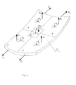
- Fig. 1 shows five of such deforming zones A, B, C, D, and E.
- the main curvature radii R A , R B , R c , R D , and R E vary insignificantly within their appropriate zones.
- An example of workpiece cross- section shown in Fig. 2 comprises three zones A, B, and C.
- the workpiece rigidity is the same within each of these zones.
- the heating-conditions are indicated in Fig. 5.
- the predetermined temperature conditions of heating over various zones is ensured by a heat flow radiated by infrared heaters.
- a different density of heat flow is predetermined within each zone.
- the heat flow density is determined in such a manner that the blank temperature would reach 195 °C simultaneously within all the zones in 0.5 hour. If uneven density of heating occurs during heating, the blank should be cooled down to have this unevenness smoothed out.
- the number of deforming steps is determined by us from the following relationship:
- the parameters of influence are established for every zone of the blank, they begin to deform the blank step by step.
- the deformation is carried out both by means of heating and by means of loading under creeping conditions below the limit of elasticity, thus ensuring that plastic deformations will not occur.
- the deforming forces are optimized, for which purpose the rate of deforming is established and varied within every zone in accordance with the emerging stresses.
- the rate of deforming is established and varied within every zone in accordance with the emerging stresses.
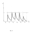
- the value of force is established within each zone which is relaxed to its minimum value (Fig. 6).
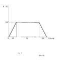
- the time of exposure in the loaded state in accordance with the curve of relaxation for this particular material at the temperature selected to be equal to 195 ° C reaches as long as 1.5 hours (Fig. 5).
- this force is reduced down to as low as zero (Fig. 6).
- the geometrical dimensions are maintained as obtained at this particular step of deforming the blank.
- the blank is subjected to heat treatment and to artificial ageing by cooling it down so that the resulting geometrical dimensions are maintained the same, said dimensions being those ones from which a judgement can be made that the predetermined contour of the workpiece is ready.
- the method according to the present invention allows also to produce the workpieces to any predetermined precision grade so that there is no need to size the workpiece any more after the process is carried out. Therewith, not only the manual labour is eliminated completely, but also the distortions are prevented that were possible earlier in the micro and macro structures of the material and could lead to a reduction in the service life of the article.
- a device is well known in prior art to be used for forming a workpiece under creeping conditions of its material in accordance with United States Patent Specification Serial No. 3,739,617.
- this device comprises a die, a diaphragm, a heating arrangement and air supply means.
- the blank is placed on the heatable die and pressed thereto over the entire surface thereof by means of the diaphragm.
- the loading is effected by blowing air into the diaphragm.
- the blank is pressed against the die by exposing the entire sirface of the blank as a whole to the differential pressure.
- a prior art device for forming various workpieces of double curvature under creeping conditions comprising a thermal chamber provided with upper rods and lower rods arranged to be disposed coaxially therein and provided with fixing units in the form of turnable plates shaped as individual parts of the contour as predetermined for the finished workpiece, said device comprising also individual driving members such as screw-and-nut pairs as well as an electric motor (see, for instance, Inventor's Certificate Specification Serial No. 1147471, Int. Cl. B21 D 11/20, i.e., the most relevant prior art).
- the devices described herein above are capable of ensuring only a restricted movement of the parallel rods limited only to one direction - a factor which does not allow to control the deforming of the blank and limits substantially the range of final configurations attainable for the workpieces thus produced.
- the third disadvantage consists in that with emerging over-stresses the necessary deformations lead to the distruction of the micro structure of the workpiece material, thereby laying the causes for the future destruction of the article already into the technology of its manufacture.
- the method according to the present invention can be implemented by using a device for forming various workpieces, comprising a thermal chamber provided with a heater and also with upper rods and lower rods having driving members and connected to the fixing units for fixing the workpiece, wherein, in conformity with the invention now claimed, said thermal chamber is provided additionally with a multisectional housing which is inserted therein and which has the sections thereof connected pivotally with each other and secured to said fixing units arranged to be disposed at the joints of the sections, said heater being therewith arranged to be disposed in each of said sections, whereas each of said sections is provided with a cooling arrangement inserted therein, and in each of said sections those portions of the workpiece are to be positioned which constitute essentially heating zones, cooling zones and loading zones, said fixing units for fixing the workpiece are provided with spherical pivots through which said fixing units are connected to the driving rods made in the form of hydraulic cylinders attached to the frame of said thermal chamber so that they are swivellable therein, said fixing units serving therewith as the
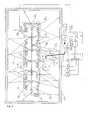
- the device for the manufacture of the workpieces in accordance with the present invention comprises a thermal chamber 1 provided with a supporting frame on which a heater 2 is arranged to be disposed, said device also comprises driving members 3 with upper and lower rods 4 connected to fixing units 5 for fixing a workpiece 6.
- the fixing unit 5 is provided with a plate 11
- the hydraulic cylinders 3 comprise displacement transducers 12 and load gauges 13 and they are attached to the frame of the thermal chamber so that they are capable of being swivelled therein.
- Each of the sections is provided with a sensor 14 for measuring the temperature and relative deformations therein as well as with a displacement measuring unit 15.
- the latter consists of a spherical pivot with a plate, wherein rods 16 of linear displacement transducers 17 attached pivotally to the wall of the thermal chamber 1 are secured.
- the multisectional housing is provided with grips 18 at the ends thereof for gripping the workpiece 6 thereby.
- All the sensing elements have their outputs connected through normalizers 19 to the appropriate inputs of analog-to-digital converter 20 of a control computing device 21.
- the outputs of the control computing device 21 are connected to an electrohydraulic commutator 22 and to an electrohydraulic transducer 23 which has the pressure and drain pipelines thereof connected to an oil pumping unit 24.
- Another output of the control computing device is connected to electric-power thyristor controllers 25 joined to bus-bars 26 to which the infra-red sources 2 are connected.
- FIG. 7 shows schematically only one thyristor controller, one hydraulic cylinder and one displacement transducer, whereas the positions of all the other elements is indicated by lines.
- the control computing device 21 comprises, besides the multichannel analog-to-digital converter 20, also a micro computer 27, a multichannel digital-to-analog converter 28, output means 29 for reading out the digitized signals, and a control element 30 for controlling the thyristors.
- the device for forming the workpieces in accordance with the present invention operates as follows (Fig. 7 and Fig. 8).
- the multisectional housing 7 is set by means of the rods 4 of the hydraulic cylinders 3 into its initial, for instance, horizontal position so that a clearance is thus ensured in between the fixing units of the upper and lower rods. Then a workpiece 6 is inserted into this clearance and clamped therein by means of the hydraulic cylinder rods.
- the displacement measuring units 15 of the linear displacement transducers 17 and the sensors 14 for measuring the temperature and relative deformations are mounted to the workpiece.
- control computing device 21 regulates the heating temperature of the workpiece 6 within the specified zones, using the thyristor controllers 25 to meter the electric power supplied to the infra-red sources 2. In doing so, use is made of the feedback ensured by the temperature sensors 14.
- control computing device 21 will load and deform the workpiece 6 by the rods 4 of the hydraulic cylinders 3 in accordance with the predetermined program.
- the design of the device now claimed makes it possible to ensure the three-dimensional loading and deformation of the blank due to that several push rods of hydraulic cylinders are united in a single fixing unit through the spherical pivot.
- the push rods of three hydraulic cylinders are united in a fixing unit, it becomes possible to control one normal component of the load and two tangential components of the load as applied to the workpiece.
- the displacements of the workpiece are monitored by the linear displacement transducers 17. If as many as up to three rods of linear displacement transducers are united in a single measuring unit through a spherical pivot, it becomes possible to take the measurements of the normal component and two tangential components of the workpiece displacement. These data are sent through the normalizers 19 and the multichannel analog-to-digital converter 20 to the micro computer 27 which compares the workpiece position against those specified in accordance with the program.
- the micro computer 27 sends appropriate signals to the multichannel analog-to-digital converter 28 and the digitized-signal output means 29 to control the forces developed and the displacements travelled by the push rods 8 of the hydraulic cylinders by means of the electrohydraulic transducer 23 to which the hydraulic cylinders 3 are connected in turn through the electrohydraulic commutator 22. Then, the workpiece thus formed is cooled down by means of the cooling arrangement 9. Every time this occurs, the fixing units maintain the resulting workpiece configuration. The process of forming is terminated as soon as the workpiece reaches its predetermined configuration (Fig. 8).
- the device now claimed ensures the opportunity for independent three-dimensional application of forces and moments, including the forces of tension/compression applied to the workpiece in the median plane, and this opportunity allows to deform the workpieces of complicated configuration with large deflections.
- the thermal chamber frame itself is made in the form of a multisectional housing, some sections of the housing being therewith provided with drives for the displacement thereof in the space, the housing sections of the thermal chamber frame are provided with drives mounted thereto and having rods for loading and deforming the blank directly, each of the sections is provided with heaters and cooling arrangements, whereas the sections are connected with each other by means of pivots.
- Fig. 9 illustrates such a device for forming a workpiece with large deflections of the blank.
- the housing of the thermal chamber frame consists of sections 31 provided with drives 32.
- the sections 31 are provided with local short-travel loading devices (or drives) 33 which are attached thereto and which deform the blank of workpiece 6 directly each within its own zone.
- the sections 31 are also provided with heaters 2 and cooling arrangements 9 attached thereto.
- the drives 32 and 33 are provided with displacement transducers and load gauges, and they are connected to the system of control over the process of forming in the same manner as the drives 3 in Fig. 7.
- the process of forming is carried out in accordance with the process described herein above, the loading being carried out within each of the zones by the local short-travel drives 33 within the ranges of their possible travels, whereas the control system 21 compensates for the inadequate rod travel of the local drives 33 by means of moving the sections 31 in the space by the drives 32 so that the sections 31 are positioned equidistantly with respect to the curved surface of the blank of the workpiece 6.
- Such a design of the device according to the present invention allows to carry out forming of the workpieces with rather large deflections of the blank.
- the loads are transmitted to the workpiece in a simpler manner, and the drives can operate easier within the hot zone since only short-travel drives are used here and the direction in which the forces exerted by these local drives are acting will change insignificantly in the process of forming the workpiece.
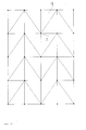
- the sections 31 may feature a triangular or polygonal configuration in the plan view, thus forming a plurality of approximating flat elements incorporated into a three-dimensional configuration (or a grid), wherein the pivots connecting the sections with each other serve as the units.
- Fig. 10 shows a layout of the sections 31 having a triangular configuration in the plan view and intended for forming a workpiece having a rectangular configuration in the plan view.
- the sections 31 can be connected with each other by means of spherical pivots 34.
- spherical pivots 34 In the most general case for an all-purpose device it is necessary to provide as many pivots 34 and drives 32 for moving the sections 31 as possible so that it would be possible to connect the pivots 34 and the drives 32 as required for working with a particular workpiece 6 depending upon the configuration class of these workpieces.
Abstract
A method of manufacturing workpieces (6) and a device for effecting the same are related to the field of plastic metal working and can be used in machine building industry.
In order to improve the precision and strength of the workpieces (6) and to extend their service life, the workpiece blank is subdivided into heating zones, loading zones and cooling zones. The number of deforming steps is determined, the workpiece (6) is deformed under creeping conditions with stresses below the limit of elasticity, and, to avoid irreversible deformations, the stresses are relaxed. For this purpose, the thermal chamber (1) is provided with a multisectional housing (7) which has its sections (8) connected pivotally with each other where each section (8) has its own heater (2) and cooler (9), and within each of the zones a portion of the workpiece blank (6) is to be positioned which has the same geometrical and thermal physical properties throughout it.
Description
- The present invention relates to plastic metal working and can be used in machine building industry for the manufacture of workpieces from sheets, sections, and monolithic and welded panels forming a working surface of single or double curvature. Incidentally, a method is well known in prior art to be used for forming a workpiece under conditions when its material creeps (see, for instance, United States Patent Specification Serial No. 3,739,617). A blank is placed on a heated die and pressed thereto over the entire surface thereof by means of a diaphragm. Then the die is heated up uniformly so that it reaches a predetermined temperature. The blank is loaded by blowing air into the diaphragm (i.e., by differential pressure) so as to pressurize the diaphragm continuously over the entire surface of the blank until it fits completely the die.
- However, when such forming is effected in accordance with this method of prior art knowledge by applying a uniform force ( caused by the pressure built up in the diaphragm), a number of various deformations cannot be realized as necessary for producing the workpieces having complicated configurations. A continuous uniform force applied to the blank fails to ensure high precision of the finished workpiece when it is made from a blank having different rigidities within various portions thereof. Because of the uniform continuous heating of the die, some portions of the blank, if it has variable thickness and rigidity, can get heated up unevenly - a factor which is detrimental to the accuracy of the finished workpiece and which increases the additional stresses, For these reasons, it is impossible to obtain such strength characteristics of the workpiece material that are high enough, since the stresses emerging in the processes of straining may be higher than the limit of elasticity for this material so that plastic fractures may result which lead to a reduction in the strength properties of the workpiece material.
- Also, another method is well known in prior art to be used in accordance with Inventor's Certificate Specification Serial No. 1147471, Int. Cl.
B21 D 11/20, wherein a blank is fixed in a plurality of points by means of movable rods arranged to be disposed coaxially with each other, then heated up to a predetermined temperature and deformed by moving the rods. This ensures the deformation of metal around the contour defined by the end faces of the stationary rods arranged to be disposed on the side of the workpiece bottom surface. - However, when such forming is affected in accordance with this method of prior art knowledge, the force applied to the fixed points of the workpiece throughout the entire process of deformation does not allow to realize a number of various deformations as necessary for producing the workpieces having complicated configurations. The deviation from the predetermined configuration seems to increase also due to the fact that it is actually impossible to make an exact allowance for the springing action since there are differences both in the geometrical parameters and in the thermal physical properties between various portions of the blank, i.e., the optimum conditions of deformation are not observed within some portions thereof - a factor which contributes to a reduction in the precision of forming as well as in the quality of the workpiece and its strength properties.
- Incidentally, the method as taught by Inventor's Certificate Specification Serial No. 1147471 is essentially the mearest one to the method now claimed as far as the material features thereof and the useful results attainable are concerned so that it is, therefore, this particular method that has been selected by us to be the most representative one of the state of prior art.
- It is an object of the present invention to improve the precision of forming the workpieces from flat blanks having a complicated relief of their surface as well as to improve their strength and service life by ensuring that the micro structure thereof is intact when irreversible deformations are made, This purpose is attained by the method of forming a workpiece from a flat blank or a curvilinear blank, wherein it is heated up and loaded under creeping conditions, said method being characterized in that said blank has the surface thereof subdivided into loadings zones, heating zones and cooling zones so that the loading zones are selected therewith depending upon the homogeneity of geometrical parameters and mechanical properties for every particular portion of said blank, whereas the heating zones and the cooling zones are selected depending upon the homogeneity of geometrical parameters and thermal physical properties of every particular portion of said blank. For every such zone its maximum value of deformation Emax is then determined depending upon the configuration of the finished workpiece in this particular zone. In addition to this, the maximum allowable deformations at a predetermined temperature, Ee, is determined thereupon, and the value of the latter is used for determining the allowable displacements of the loading points within the boundaries of every loading zone. Then, the number of blank deforming steps is determined from the ratio of whereupon the blank is heated up until a predetermined distribution of temperatures is reached within every such zone and then cooled down to have the unevenness of heating density smoothed out. After this, the blank is deformed step by step, the rate of deforming being varied at every step both by heating and by loading under creeping conditions below the limit of elasticity. During temperature strain, the rate of deforming ET is varied in proportion to the value of exT, whereas during loading the rate H of deformation is varied in proportion to the value of kom, whereas under the combined influence of heating and loading the deformation rate is varied in proportion to the value of exT • kσm, where e = natural logarithm base; x = coefficient depending upon the properties of the material used; T = heating temperature; k = coefficient of proportionality; a = deformation stress; and m = exponent of power.
- At the end of every step, for each zone the value of force is established which gets relaxed down to its minimum value, and at the end of the last step it gets relaxed down to zero. In doing so, in the process of relaxation the geometrical dimensions are maintained as obtained at this particular step of deforming the blank, and after the last step the blank is subjected to heat treatment and to artificial ageing by cooling it down so that the resulting geometrical dimensions are maintained the same, said dimensions being those ones from which a judgement can be made that the predetermined contour of the workpiece is ready.
- The method as claimed in accordance with the present invention will be discussed herein below in greater detail with reference to accompanying drawings Nos. 1, 2, 3, 4, 5, 6, 7, 8, 9 and 10 illustrating a particular embodiment thereof, wherein:
- Fig. 1 shows schematically a workpiece of variable-thickness double-curvature monolithic panel type in accordance with the present invention;
- Fig. 2 shows a cross section of a flat blank made from two materials of different kinds;
- Fig. 3 illustrates a step-by-step variation of the workpiece contour;
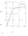
- Fig. 4 is a diagram showing the relationsip of σ-E;
- Fig. 5 indicates the heating conditions;
- Fig. 6 illustrates the steps of loading and relaxation under the heating conditions;
- Fig. 7 is a schematic diagram of a device for effecting the method in accordance with the present invention, said device being shown in its initial position;
- Fig. 8 shows the same, but when the device is in its working position;
- Fig. 9 is a schematic diagram of a device for effecting large deflections in accordance with the present invention; and
- Fig. 10 illustrates a triangular-shaped section of a multisectional housing.
- Now with reference to the accompanying drawings, a method of forming and heat-treating a workpiece in accordance with the present invention consists in the following.
- A flat blank or a curvilinear blank is subdivided into zones of deforming. The dimensions and configurations of these zones of deforming are to be selected so that the changes in the curvature and rigidity of the workpiece would not exceed appropriate predetermined values within a single particular zone. Fig. 1 shows five of such deforming zones A, B, C, D, and E. The main curvature radii RA, RB, Rc, RD, and RE vary insignificantly within their appropriate zones. An example of workpiece cross- section shown in Fig. 2 comprises three zones A, B, and C. The workpiece rigidity is the same within each of these zones.
- Let us give an example of forming a workpiece from a blank made of aluminium alloy Grade AK-1. The heating-conditions are indicated in Fig. 5. The predetermined temperature conditions of heating over various zones is ensured by a heat flow radiated by infrared heaters. A different density of heat flow is predetermined within each zone. The heat flow density is determined in such a manner that the blank temperature would reach 195 °C simultaneously within all the zones in 0.5 hour. If uneven density of heating occurs during heating, the blank should be cooled down to have this unevenness smoothed out. The curvature radius which must be obtained for the finished workpiece after forming is selected to be equal to R = 1100 mm.
- The maximum deformation required for the outermost fibre is determined from the analysis of the workpiece contour. In this particular case, it can be calculated using the following familiar formula: Emax = K , where y workpiece thickness; and R = curvature radius; Emax = 0.8 %.
- Realizing the curve of deforming σ-∈ (Fig. 4), at 195 °C we determine the portion thereof within which the relationship between the deformations and stresses is linear, and at this portion we select the value of maximum allowable elastic deformation Ee.
- In our case, Ee < 0.45 %, so we select Ee = 0.4 %.
- The number of deforming steps is determined by us from the following relationship:

- To our opinion, the process can be subdivided into two steps.
- Knowing the curvature of the beam bent axis R = M J, where M = bending moment; and J = moment of inertia in the cross section, one can determine the forces that are required as wall as the deflections and turning angles at every fixed point for particular calculated radii of curvature at every deforming step. With the blank thickness ratios selected, e.g., for the two zones (Fig. 2) to be hi = 2 mm and h2 = 6 mm, the bending moment M2 for the second zone is 24 times as high as Mi.
- After the parameters of influence are established for every zone of the blank, they begin to deform the blank step by step. At every step the deformation is carried out both by means of heating and by means of loading under creeping conditions below the limit of elasticity, thus ensuring that plastic deformations will not occur. In order to avoid accumulating the residual stresses in the deforming process, the deforming forces are optimized, for which purpose the rate of deforming is established and varied within every zone in accordance with the emerging stresses. Thus, during temperature strain the deformation rate ET is changed in proportion to the value of exT, whereas in loading they vary the deformation rate in proportion to the value kam. When both heating and loading are effected at the same time, the deformation rate is ; ø exTkam, where e = natural logarithm base; x = coefficient depending upon the properties of the material used; T = heating temperature; k = coefficient of proportionality; a = deformation stress; and m = exponent of power.
- Under these conditions, one-to-one correspondence is established between the deformation forces and the stresses emerging in the workpiece and the deformation rates at a predetermined temperature within every zone. Hence, by varying the magnitude of force or the temperature within a particular zone, they can vary the deformation rate.
- At the end of a step the value of force is established within each zone which is relaxed to its minimum value (Fig. 6). In our example the time of exposure in the loaded state in accordance with the curve of relaxation for this particular material at the temperature selected to be equal to 195 °C reaches as long as 1.5 hours (Fig. 5). At the end of the last step this force is reduced down to as low as zero (Fig. 6). In the process of relaxation the geometrical dimensions are maintained as obtained at this particular step of deforming the blank. After the last step the blank is subjected to heat treatment and to artificial ageing by cooling it down so that the resulting geometrical dimensions are maintained the same, said dimensions being those ones from which a judgement can be made that the predetermined contour of the workpiece is ready.
- As soon as the process of cooling and relieving the loads is over, the resulting shape is checked.
- The experiments have shown that the method of forming as described herein above allows to realize various kinds of loading the workpiece, i.e., the deforming procedure can be effected by uneven tension, compression and shear in the median surface, and this extends substantially the range of the workpiece shapes that can be obtained.
- Since the conditions of forming are optimized, the method according to the present invention allows also to produce the workpieces to any predetermined precision grade so that there is no need to size the workpiece any more after the process is carried out. Therewith, not only the manual labour is eliminated completely, but also the distortions are prevented that were possible earlier in the micro and macro structures of the material and could lead to a reduction in the service life of the article.
- A device is well known in prior art to be used for forming a workpiece under creeping conditions of its material in accordance with United States Patent Specification Serial No. 3,739,617. As it is taught by the above-mentioned patent specification, this device comprises a die, a diaphragm, a heating arrangement and air supply means. The blank is placed on the heatable die and pressed thereto over the entire surface thereof by means of the diaphragm. The loading is effected by blowing air into the diaphragm. The blank is pressed against the die by exposing the entire sirface of the blank as a whole to the differential pressure.
- It is a disadvantage of this prior art device that in forming a workpiece from a blank having a complicated relief of its surface where there are portions of various rigidities the desirable contour cannot be reached with the suitable precision, whereas some portions thereof are inevitably overstressed with a resulting destruction of the micro structure during irreversible deformations.
- The nearest to the invention now claimed in the technical essence and technical level is a prior art device for forming various workpieces of double curvature under creeping conditions, comprising a thermal chamber provided with upper rods and lower rods arranged to be disposed coaxially therein and provided with fixing units in the form of turnable plates shaped as individual parts of the contour as predetermined for the finished workpiece, said device comprising also individual driving members such as screw-and-nut pairs as well as an electric motor (see, for instance, Inventor's Certificate Specification Serial No. 1147471, Int. Cl.
B21 D 11/20, i.e., the most relevant prior art). - However, the devices described herein above are capable of ensuring only a restricted movement of the parallel rods limited only to one direction - a factor which does not allow to control the deforming of the blank and limits substantially the range of final configurations attainable for the workpieces thus produced.
- Another disadvantage of prior art devices is constituted by low precision attainable in the manufacture of the workpieces. This low precision in forming is caused by the springing action of the workpieces after they are formed to the shape, which springing action cannot have its magnitude taken accurately into account when making the forming equipment because of variations in the mechanical properties shown by the material of blanks and their geometrical dimensions within the tolerable limits.
- The third disadvantage consists in that with emerging over-stresses the necessary deformations lead to the distruction of the micro structure of the workpiece material, thereby laying the causes for the future destruction of the article already into the technology of its manufacture.
- It is an object of the device now claimed to improve the precision of deforming the workpieces from flat blanks having a complicated relief of their surface as well as to improve their strength and service life by ensuring that the micro structure thereof remains intact while irreversible deformations are being made.
- The method according to the present invention can be implemented by using a device for forming various workpieces, comprising a thermal chamber provided with a heater and also with upper rods and lower rods having driving members and connected to the fixing units for fixing the workpiece, wherein, in conformity with the invention now claimed, said thermal chamber is provided additionally with a multisectional housing which is inserted therein and which has the sections thereof connected pivotally with each other and secured to said fixing units arranged to be disposed at the joints of the sections, said heater being therewith arranged to be disposed in each of said sections, whereas each of said sections is provided with a cooling arrangement inserted therein, and in each of said sections those portions of the workpiece are to be positioned which constitute essentially heating zones, cooling zones and loading zones, said fixing units for fixing the workpiece are provided with spherical pivots through which said fixing units are connected to the driving rods made in the form of hydraulic cylinders attached to the frame of said thermal chamber so that they are swivellable therein, said fixing units serving therewith as the places for applying the loading forces thereto so that they are capable of being moved in accordance with deformation of the workpiece. The device according to the present invention can be understood from the accompanying drawings.
- Now with reference to the accompanying drawings (Fig. 7) the device for the manufacture of the workpieces in accordance with the present invention comprises a thermal chamber 1 provided with a supporting frame on which a
heater 2 is arranged to be disposed, said device also comprises drivingmembers 3 with upper andlower rods 4 connected to fixingunits 5 for fixing aworkpiece 6. What is novel here is that the thermal chamber 1 is provided additionally with amultisectional housing 7 which is inserted therein and which has a plurality ofsections 8 connected pivotally with each other and secured to the fixingunits 5, that theheater 2 has therewith its sections arranged to be disposed and fixed in each of thesections 8, whereas each of these sections is provided with acooling arrangement 9 inserted therein, that in each of the above-mentioned sections those portions of theworkpiece 6 are to be positioned which constitute essentially heating zones and cooling zones, that there are also loading zones defined by the fixingunits 5 designed for fixing theworkpiece 6, and that the fixingunits 5 are provided withspherical pivots 10 through which these fixing units are connected to therods 4 of the drives made in the form ofhydraulic cylinders 3 attached to the frame of the thermal chamber so that they are capable of being swivelled therein, the fixingunits 5 serving therewith as the places for applying the loading forces thereto so that they are capable of being moved in accordance to the deformation inflicted to theworkpiece 6. - In addition to this, the reference numerals used in Figs. 7 and 8 have the following meanings: the fixing
unit 5 is provided with aplate 11, thehydraulic cylinders 3 comprisedisplacement transducers 12 and load gauges 13 and they are attached to the frame of the thermal chamber so that they are capable of being swivelled therein. Each of the sections is provided with a sensor 14 for measuring the temperature and relative deformations therein as well as with adisplacement measuring unit 15. The latter consists of a spherical pivot with a plate, whereinrods 16 oflinear displacement transducers 17 attached pivotally to the wall of the thermal chamber 1 are secured. The multisectional housing is provided withgrips 18 at the ends thereof for gripping theworkpiece 6 thereby. - All the sensing elements have their outputs connected through
normalizers 19 to the appropriate inputs of analog-to-digital converter 20 of acontrol computing device 21. The outputs of thecontrol computing device 21 are connected to anelectrohydraulic commutator 22 and to anelectrohydraulic transducer 23 which has the pressure and drain pipelines thereof connected to anoil pumping unit 24. Another output of the control computing device is connected to electric-power thyristor controllers 25 joined to bus-bars 26 to which the infra-red sources 2 are connected. - For simplicity, Fig. 7 shows schematically only one thyristor controller, one hydraulic cylinder and one displacement transducer, whereas the positions of all the other elements is indicated by lines.
- The
control computing device 21 comprises, besides the multichannel analog-to-digital converter 20, also amicro computer 27, a multichannel digital-to-analog converter 28, output means 29 for reading out the digitized signals, and acontrol element 30 for controlling the thyristors. - The device for forming the workpieces in accordance with the present invention operates as follows (Fig. 7 and Fig. 8).
- The
multisectional housing 7 is set by means of therods 4 of thehydraulic cylinders 3 into its initial, for instance, horizontal position so that a clearance is thus ensured in between the fixing units of the upper and lower rods. Then aworkpiece 6 is inserted into this clearance and clamped therein by means of the hydraulic cylinder rods. Thedisplacement measuring units 15 of thelinear displacement transducers 17 and the sensors 14 for measuring the temperature and relative deformations are mounted to the workpiece. - The data related to the final configuration of the workpiece, to the allowable values of stresses, to the relative deformations, forces, displacements and temperatures and also to the time schedule of heating up and deforming the workpiece as well as such data characterizing this particular installation and necessary for shaping up the control influences as the coordinates of workpiece fixing points and hydraulic cylinder-to-thermal chamber frame attachment points, the calibration characteristics of sensing elements, the number of zones under control, their addresses, etc. are set into the
control computing device 21. - In conformity with heating time schedule, the
control computing device 21 regulates the heating temperature of theworkpiece 6 within the specified zones, using thethyristor controllers 25 to meter the electric power supplied to the infra-red sources 2. In doing so, use is made of the feedback ensured by the temperature sensors 14. - As soon as the predetermined distribution of temperatures is reached throughout the
workpiece 6, thecontrol computing device 21 will load and deform theworkpiece 6 by therods 4 of thehydraulic cylinders 3 in accordance with the predetermined program. - The design of the device now claimed makes it possible to ensure the three-dimensional loading and deformation of the blank due to that several push rods of hydraulic cylinders are united in a single fixing unit through the spherical pivot. Thus, in particular, if the push rods of three hydraulic cylinders are united in a fixing unit, it becomes possible to control one normal component of the load and two tangential components of the load as applied to the workpiece.
- The displacements of the workpiece are monitored by the
linear displacement transducers 17. If as many as up to three rods of linear displacement transducers are united in a single measuring unit through a spherical pivot, it becomes possible to take the measurements of the normal component and two tangential components of the workpiece displacement. These data are sent through thenormalizers 19 and the multichannel analog-to-digital converter 20 to themicro computer 27 which compares the workpiece position against those specified in accordance with the program. In case if the error exceeds the allowable value, themicro computer 27 sends appropriate signals to the multichannel analog-to-digital converter 28 and the digitized-signal output means 29 to control the forces developed and the displacements travelled by thepush rods 8 of the hydraulic cylinders by means of theelectrohydraulic transducer 23 to which thehydraulic cylinders 3 are connected in turn through theelectrohydraulic commutator 22. Then, the workpiece thus formed is cooled down by means of thecooling arrangement 9. Every time this occurs, the fixing units maintain the resulting workpiece configuration. The process of forming is terminated as soon as the workpiece reaches its predetermined configuration (Fig. 8). - Thus, the device now claimed ensures the opportunity for independent three-dimensional application of forces and moments, including the forces of tension/compression applied to the workpiece in the median plane, and this opportunity allows to deform the workpieces of complicated configuration with large deflections.
- This extends the range of the final configurations thus attainable as well as the range of workpiece types that can be manufactured in accordance with this technology. Since the forces applied and the displacements obtained are monitored and controlled, the process of forming can be adapted to the mechanical properties of each particular workpiece and the forming conditions optimized at every fixed point with a resulting improvement in the precision to which the workpieces thus produced conform the predetermined configuration and a reduction in the quantity of products rejected. In addition to this, the independent regulation of loads and temperatures in some zones to ensure the desirable configuration of the workpiece allows to reduce the manufacturing costs related with the manufacture of equipment for a particular workpiece together with the adjustment of this equipment that is to follow thereafter.
- In the case when very large deflections and displacements of the blank take place while the workpiece is being formed, it seems reasonable to make use of a modified device for effecting the method described above.
- In this implementation the thermal chamber frame itself is made in the form of a multisectional housing, some sections of the housing being therewith provided with drives for the displacement thereof in the space, the housing sections of the thermal chamber frame are provided with drives mounted thereto and having rods for loading and deforming the blank directly, each of the sections is provided with heaters and cooling arrangements, whereas the sections are connected with each other by means of pivots.
- Fig. 9 illustrates such a device for forming a workpiece with large deflections of the blank.
- The housing of the thermal chamber frame consists of sections 31 provided with
drives 32. The sections 31 are provided with local short-travel loading devices (or drives) 33 which are attached thereto and which deform the blank ofworkpiece 6 directly each within its own zone. The sections 31 are also provided withheaters 2 andcooling arrangements 9 attached thereto. Thedrives drives 3 in Fig. 7. - The process of forming is carried out in accordance with the process described herein above, the loading being carried out within each of the zones by the local short-travel drives 33 within the ranges of their possible travels, whereas the
control system 21 compensates for the inadequate rod travel of thelocal drives 33 by means of moving the sections 31 in the space by thedrives 32 so that the sections 31 are positioned equidistantly with respect to the curved surface of the blank of theworkpiece 6. Such a design of the device according to the present invention allows to carry out forming of the workpieces with rather large deflections of the blank. In addition to this, the loads are transmitted to the workpiece in a simpler manner, and the drives can operate easier within the hot zone since only short-travel drives are used here and the direction in which the forces exerted by these local drives are acting will change insignificantly in the process of forming the workpiece. - Where the workpieces to be formed have double curvature with large deflections, the sections 31 may feature a triangular or polygonal configuration in the plan view, thus forming a plurality of approximating flat elements incorporated into a three-dimensional configuration (or a grid), wherein the pivots connecting the sections with each other serve as the units.
- Fig. 10 shows a layout of the sections 31 having a triangular configuration in the plan view and intended for forming a workpiece having a rectangular configuration in the plan view. The sections 31 can be connected with each other by means of
spherical pivots 34. In the most general case for an all-purpose device it is necessary to provide asmany pivots 34 and drives 32 for moving the sections 31 as possible so that it would be possible to connect thepivots 34 and thedrives 32 as required for working with aparticular workpiece 6 depending upon the configuration class of these workpieces.
Claims (10)
1. Method of forming a work piece (6) from a flat blank or a curvilinear blank, wherein said workpiece (6) is heated up and loaded under creeping conditions, with a surface of said blank being subdivided into zones, characterized in that said zones are loading zones, heating zones and cooling zones, with the loading zones being selected such that the geometrical parameters and mechanical properties are as homogenous as possible for every particular portion of said blank, whereas the heating zones and cooling zones are selected such that the geometrical parameters and thermal physical properties of said blank are as homogenous as possible, that for every such zone the number of deforming steps is determined by the ratio of the maximum desired value of deformation Emax by the maximum allowable deformations Ee at a predetermined temperature, which is allowed for loading under creeping conditions below the limit of elasticity, whereupon the blank is heated up until a predetermined distribution of temperatures is reached with every such zone and then cooled down to have the unevenness of heating density smoothed out, with said single deformation step being repeated adapting the heating and loading at every step.
2. Method according to claim 1, characterized in that during temperature strain, the rate of deforming ;T is varied in proportion to the value exT, whereas during loading the rate of deforming EH is varied in proportion to the value k am, where
e = natural logarithm base;
x = coefficient depending upon the properties of the material used;
T = heating temperature;
k = coefficient of proportionality;
a = deformation stress;
m = exponent of power.
3. Method according to claim 2, characterized in that under the combined influence of heating and loading the deformation rate is varied in proportion to value exT * k a m.
4. Method according to one of the preceding claims characterized in that at the end of every step of deformation, the force exerted for each zone is reduced to its minimum value, and at the end of the last step relaxed down to zero, by this achieving a process of relaxation maintaining the geometrical dimensions as obtained at this particular step of deforming, and that after the last step the blank (6) is subjected to heat treatment and to artificial ageing by cooling it down so that the resulting geometrical dimensions are maintained, with said dimensions being those from which a judgement can be made that the predetermined contour of the workpiece is ready.
5. Device for forming various workpieces (6), comprising a thermal chamber (1) provided with a heater (2) and loading rods (4) arranged to be disposed inside the thermal chamber (1), said loading rods (4) having driving,members (3), characterized in that said thermal chamber (1) comprises a multisectional housing (7) for receiving a workpiece to be formed, said housing (7) being preferably inserted in said thermal chamber (1), and which housing (7) has sections (8) connected pivotally with each other and secured pivotally to workpiece fixing units (5).
6. Device recording to claim 5, characterized in that said workpiece fixing units (5) are arranged to be disposed at the joints of the sections (8), said heater (2) being therewith arranged to be disposed in each of said section (8), whereas each of said sections (8) is provided with a cooling arrangement (9) inserted therin, and inside each of said sections (8) those portions of the workpiece (6) are to be positioned which constitute essentially heating zones, cooling zones and loading zones.
7. Device according to one of the claims 5 and 6, characterized in that said workpiece fixing units (5) are provided with spherical pivots (4) through which said workpiece fixing units (5) are connected to the loading rods (4) of the drive elements made in the form of hydraulic cylinders (3) attached to said thermal chamber (1) so that they are capable of being swivelled therein, said workpiece fixing units (5) serving therewith as the places for applying the loading forces thereto so that they are capable of being moved in accordance with the deformation of the workpiece (6).
8. Device according to one of the claims 5, 6 and 7, characterized in that the faces of said sections (8) facing said workpiece (6) are made so that they are capable of being equidistant with respect to said workpiece surfaces while the latter are being deformed.
9. Device according to one of the claims 5 to 8, characterized in that the thermal chamber (1) and said multisectional housing (7) are combined with one another and are made integrally, that the hydraulic cylinders (33) of those rods which are in contact with the blank are secured pivotally directly to the housing (7) of the sections (8) and that the hydraulic cylinders (32) of those rods which are in contact with the sections (8) are secured pivotally to external supports.
10. Device according to one of the claims 5 to 9, characterized in that said multisectional housing (7) is made in the form of a spatially flat- type figure consisting of sections (31) having a predetermined geometrical configuration, e.g. a triangular prism.
Priority Applications (3)
| Application Number | Priority Date | Filing Date | Title |
|---|---|---|---|
| EP92110480A EP0575646A1 (en) | 1992-06-22 | 1992-06-22 | A method and a device for forming various workpieces |
| US07/973,104 US5345799A (en) | 1992-06-22 | 1992-11-06 | Method and device for forming various workpieces |
| CA002086579A CA2086579A1 (en) | 1992-06-22 | 1992-12-31 | Method and a device for forming various workpieces |
Applications Claiming Priority (1)
| Application Number | Priority Date | Filing Date | Title |
|---|---|---|---|
| EP92110480A EP0575646A1 (en) | 1992-06-22 | 1992-06-22 | A method and a device for forming various workpieces |
Publications (1)
| Publication Number | Publication Date |
|---|---|
| EP0575646A1 true EP0575646A1 (en) | 1993-12-29 |
Family
ID=8209733
Family Applications (1)
| Application Number | Title | Priority Date | Filing Date |
|---|---|---|---|
| EP92110480A Withdrawn EP0575646A1 (en) | 1992-06-22 | 1992-06-22 | A method and a device for forming various workpieces |
Country Status (3)
| Country | Link |
|---|---|
| US (1) | US5345799A (en) |
| EP (1) | EP0575646A1 (en) |
| CA (1) | CA2086579A1 (en) |
Cited By (4)
| Publication number | Priority date | Publication date | Assignee | Title |
|---|---|---|---|---|
| EP0904866A2 (en) * | 1997-09-24 | 1999-03-31 | Mitsubishi Heavy Industries, Ltd. | Automatic plate bending system using high frequency induction heating |
| EP0904867A2 (en) * | 1997-09-29 | 1999-03-31 | Mitsubishi Heavy Industries, Ltd. | Method and system for determining heating point and heating line in bending of steel plate |
| WO1999044765A1 (en) * | 1998-03-05 | 1999-09-10 | Jong Gye Shin | Automatic machine for the formation of ship's curved hull-pieces |
| WO2002051564A1 (en) * | 2000-12-23 | 2002-07-04 | Simone Rubbert | Method for shaping flat bodies to give irregular multi-dimensional curved objects |
Families Citing this family (13)
| Publication number | Priority date | Publication date | Assignee | Title |
|---|---|---|---|---|
| DE4405027A1 (en) * | 1993-02-18 | 1994-11-10 | Hasenclever Maschf Sms | Method and apparatus for applying a temperature profile to metal billets intended for extrusion |
| SE516374C2 (en) * | 2000-02-22 | 2002-01-08 | Workpiece controlled shaping of metal, preferably in the form of plates or bands, comprises heating the workpiece across notches or zones to reduce locally the tensile strength | |
| JP2002241835A (en) * | 2001-02-20 | 2002-08-28 | Aisin Takaoka Ltd | Method for partially strengthening work |
| GB2381764A (en) * | 2001-11-08 | 2003-05-14 | Farleydene Ltd | Autoclave suitable for heat treating parts |
| WO2004028718A1 (en) * | 2002-09-30 | 2004-04-08 | Zenji Horita | Method of working metal, metal body obtained by the method and metal-containing ceramic body obtained by the method |
| GB0229434D0 (en) * | 2002-12-18 | 2003-01-22 | Bae Systems Plc | Aircraft component manufacturing tool and method |
| US7523633B1 (en) * | 2005-10-27 | 2009-04-28 | Mielke Laurence H | Wire tray jig and bending method |
| GB2463642B (en) * | 2008-09-17 | 2012-08-29 | Rolls Royce Plc | Press tool arrangement |
| US8607603B2 (en) * | 2010-04-30 | 2013-12-17 | Warsaw Orthopedic, Inc. | Systems, devices and methods for multi-dimensional bending of an elongate member |
| US8298242B2 (en) * | 2010-04-30 | 2012-10-30 | Warsaw Orthopedic, Inc. | Systems, devices and methods for bending an elongate member |
| JP6194526B2 (en) * | 2013-06-05 | 2017-09-13 | 高周波熱錬株式会社 | Method and apparatus for heating plate workpiece and hot press molding method |
| KR102313910B1 (en) * | 2017-04-26 | 2021-10-19 | 한국재료연구원 | Blow molding apparatus available for continuous process |
| CN112427520A (en) * | 2020-10-26 | 2021-03-02 | 上海凌云汽车模具有限公司 | Hot forming method for unconventional section-type metal piece and annular workpiece |
Citations (1)
| Publication number | Priority date | Publication date | Assignee | Title |
|---|---|---|---|---|
| US4888973A (en) * | 1988-09-06 | 1989-12-26 | Murdock, Inc. | Heater for superplastic forming of metals |
Family Cites Families (10)
| Publication number | Priority date | Publication date | Assignee | Title |
|---|---|---|---|---|
| US2737224A (en) * | 1951-12-10 | 1956-03-06 | Boeing Co | Apparatus for forming sheet metal |
| US2850071A (en) * | 1954-10-18 | 1958-09-02 | Daniel W Kraybill | Method and apparatus for stretchforming metal and controlling direction of pull |
| US3739617A (en) * | 1970-09-21 | 1973-06-19 | Boeing Co | High temperature vacuum creep forming fixture |
| US3745805A (en) * | 1971-08-27 | 1973-07-17 | Ladish Co | Creep annealing and a multiple pin fixture for use therein |
| FR2237435A5 (en) * | 1973-07-10 | 1975-02-07 | Aerospatiale | |
| US4212188A (en) * | 1979-01-18 | 1980-07-15 | The Boeing Company | Apparatus for forming sheet metal |
| DE3124514A1 (en) * | 1981-06-23 | 1983-01-05 | Blohm + Voss Ag, 2000 Hamburg | Process for shaping ships' plates |
| DE3245755A1 (en) * | 1982-12-10 | 1984-06-14 | Dorstener Maschinenfabrik Ag, 4270 Dorsten | Method for correcting the bending line of the bending tool of a bending press, in particular a folding press |
| JPS6156738A (en) * | 1984-08-28 | 1986-03-22 | Toyota Motor Corp | Forming of component for vehicle |
| US4592537A (en) * | 1985-01-07 | 1986-06-03 | Tocco, Inc. | Apparatus for heat treating and sizing thin walled articles |
-
1992
- 1992-06-22 EP EP92110480A patent/EP0575646A1/en not_active Withdrawn
- 1992-11-06 US US07/973,104 patent/US5345799A/en not_active Expired - Fee Related
- 1992-12-31 CA CA002086579A patent/CA2086579A1/en not_active Abandoned
Patent Citations (1)
| Publication number | Priority date | Publication date | Assignee | Title |
|---|---|---|---|---|
| US4888973A (en) * | 1988-09-06 | 1989-12-26 | Murdock, Inc. | Heater for superplastic forming of metals |
Non-Patent Citations (1)
| Title |
|---|
| SOVIET INVENTIONS ILLUSTRATED Section PQ, Week 8541, 22 November 1985 Derwent Publications Ltd., London, GB; AN 85-255013/41 & SU-A-1 147 471 (HYDRO-DYNAMICS) 30 March 1985 * |
Cited By (11)
| Publication number | Priority date | Publication date | Assignee | Title |
|---|---|---|---|---|
| EP0904866A2 (en) * | 1997-09-24 | 1999-03-31 | Mitsubishi Heavy Industries, Ltd. | Automatic plate bending system using high frequency induction heating |
| EP0904866A3 (en) * | 1997-09-24 | 2000-08-02 | Mitsubishi Heavy Industries, Ltd. | Automatic plate bending system using high frequency induction heating |
| EP1129798A2 (en) * | 1997-09-24 | 2001-09-05 | Mitsubishi Heavy Industries, Ltd. | Automatic plate bending system using high frequency induction heating |
| EP1129798A3 (en) * | 1997-09-24 | 2001-12-05 | Mitsubishi Heavy Industries, Ltd. | Automatic plate bending system using high frequency induction heating |
| EP0904867A2 (en) * | 1997-09-29 | 1999-03-31 | Mitsubishi Heavy Industries, Ltd. | Method and system for determining heating point and heating line in bending of steel plate |
| EP0904867A3 (en) * | 1997-09-29 | 2000-08-02 | Mitsubishi Heavy Industries, Ltd. | Method and system for determining heating point and heating line in bending of steel plate |
| US6298310B1 (en) | 1997-09-29 | 2001-10-02 | Mitsubishi Heavy Industries, Ltd. | Method and system for determining heating point and heating line in bending of steel plate |
| US6385556B1 (en) | 1997-09-29 | 2002-05-07 | Mitsubishi Heavy Industries, Ltd. | Method and system for determining heating point and heating line in bending of steel plate |
| US6456957B1 (en) | 1997-09-29 | 2002-09-24 | Mitsubishi Heavy Industries, Ltd. | Method and system for determining heating point and heating line in bending of steel plate |
| WO1999044765A1 (en) * | 1998-03-05 | 1999-09-10 | Jong Gye Shin | Automatic machine for the formation of ship's curved hull-pieces |
| WO2002051564A1 (en) * | 2000-12-23 | 2002-07-04 | Simone Rubbert | Method for shaping flat bodies to give irregular multi-dimensional curved objects |
Also Published As
| Publication number | Publication date |
|---|---|
| US5345799A (en) | 1994-09-13 |
| CA2086579A1 (en) | 1993-12-23 |
Similar Documents
| Publication | Publication Date | Title |
|---|---|---|
| EP0575646A1 (en) | A method and a device for forming various workpieces | |
| AU2007209756B2 (en) | Active reconfigurable stretch forming | |
| US4306436A (en) | Method and apparatus for regulating preselected loads on forming dies | |
| CN104646475A (en) | Multi-point forming method for whole aluminum alloy wall plate of aircraft | |
| US6071360A (en) | Controlled strain rate forming of thick titanium plate | |
| JPH10166059A (en) | Plate bending method | |
| US6779564B2 (en) | Method and apparatus for setting a helical compression spring | |
| US5519623A (en) | Improved bending machine and a method for bending a part | |
| RU2056197C1 (en) | Method of shaping parts and appparatus for performing the method | |
| US3344968A (en) | Trimming glass sheets | |
| CN112469673B (en) | Method for producing thermoplastic plate with paraboloid and clamping device | |
| CA2510154A1 (en) | Aircraft component manufacturing tool and method | |
| JPH0262349B2 (en) | ||
| RU2403114C1 (en) | Method of plastic straightening of titanium alloy sections | |
| EP2578331B1 (en) | Method and equipment for shaping a cast component | |
| RU2036861C1 (en) | Device for treatment of glass sheets | |
| JP2920372B2 (en) | Age forming molding method | |
| JPH11179428A (en) | Method for bending steel by heating and device therefor | |
| KR20180067010A (en) | Method for forming various curve on the plate | |
| CN111847852B (en) | Spherical forming system and method for lobster eye optical device | |
| RU2768412C1 (en) | Method and device for controlling thermal power treatment | |
| SU967613A1 (en) | Method of forming parts to shape | |
| JP2742034B2 (en) | Spring support bracket and jig for age forming of long objects | |
| JP2012187600A (en) | Method for forming sheet material, sheet material-forming apparatus, method for determining forming condition for sheet material-forming apparatus, and device for determining forming condition for sheet material-forming apparatus | |
| RU2106251C1 (en) | Apparatus for vacuum-digester molding of panels from polymeric composite materials |
Legal Events
| Date | Code | Title | Description |
|---|---|---|---|
| PUAI | Public reference made under article 153(3) epc to a published international application that has entered the european phase |
Free format text: ORIGINAL CODE: 0009012 |
|
| AK | Designated contracting states |
Kind code of ref document: A1 Designated state(s): AT BE CH DE ES FR GB IT LI NL SE |
|
| K1C3 | Correction of patent application (complete document) published |
Effective date: 19931229 |
|
| 17P | Request for examination filed |
Effective date: 19940608 |
|
| 17Q | First examination report despatched |
Effective date: 19941114 |
|
| STAA | Information on the status of an ep patent application or granted ep patent |
Free format text: STATUS: THE APPLICATION IS DEEMED TO BE WITHDRAWN |
|
| 18D | Application deemed to be withdrawn |
Effective date: 19950525 |