EP0563253B1 - High security electronic dial combination lock - Google Patents
High security electronic dial combination lock Download PDFInfo
- Publication number
- EP0563253B1 EP0563253B1 EP92903007A EP92903007A EP0563253B1 EP 0563253 B1 EP0563253 B1 EP 0563253B1 EP 92903007 A EP92903007 A EP 92903007A EP 92903007 A EP92903007 A EP 92903007A EP 0563253 B1 EP0563253 B1 EP 0563253B1
- Authority
- EP
- European Patent Office
- Prior art keywords
- lever
- cam
- lock
- cam wheel
- dial
- Prior art date
- Legal status (The legal status is an assumption and is not a legal conclusion. Google has not performed a legal analysis and makes no representation as to the accuracy of the status listed.)
- Expired - Lifetime
Links
Images


Classifications
-
- E—FIXED CONSTRUCTIONS
- E05—LOCKS; KEYS; WINDOW OR DOOR FITTINGS; SAFES
- E05B—LOCKS; ACCESSORIES THEREFOR; HANDCUFFS
- E05B47/00—Operating or controlling locks or other fastening devices by electric or magnetic means
- E05B47/06—Controlling mechanically-operated bolts by electro-magnetically-operated detents
- E05B47/0676—Controlling mechanically-operated bolts by electro-magnetically-operated detents by disconnecting the handle
- E05B47/0684—Controlling mechanically-operated bolts by electro-magnetically-operated detents by disconnecting the handle radially
- E05B47/0688—Controlling mechanically-operated bolts by electro-magnetically-operated detents by disconnecting the handle radially with a pivotally moveable coupling element
-
- E—FIXED CONSTRUCTIONS
- E05—LOCKS; KEYS; WINDOW OR DOOR FITTINGS; SAFES
- E05B—LOCKS; ACCESSORIES THEREFOR; HANDCUFFS
- E05B37/00—Permutation or combination locks; Puzzle locks
- E05B37/08—Permutation or combination locks; Puzzle locks with tumbler discs on a single axis, all the discs being adjustable by a rotary knob which is not shifted for adjusting the discs
-
- E—FIXED CONSTRUCTIONS
- E05—LOCKS; KEYS; WINDOW OR DOOR FITTINGS; SAFES
- E05B—LOCKS; ACCESSORIES THEREFOR; HANDCUFFS
- E05B47/00—Operating or controlling locks or other fastening devices by electric or magnetic means
- E05B47/0001—Operating or controlling locks or other fastening devices by electric or magnetic means with electric actuators; Constructional features thereof
- E05B47/0002—Operating or controlling locks or other fastening devices by electric or magnetic means with electric actuators; Constructional features thereof with electromagnets
- E05B47/0003—Operating or controlling locks or other fastening devices by electric or magnetic means with electric actuators; Constructional features thereof with electromagnets having a movable core
- E05B47/0004—Operating or controlling locks or other fastening devices by electric or magnetic means with electric actuators; Constructional features thereof with electromagnets having a movable core said core being linearly movable
-
- E—FIXED CONSTRUCTIONS
- E05—LOCKS; KEYS; WINDOW OR DOOR FITTINGS; SAFES
- E05B—LOCKS; ACCESSORIES THEREFOR; HANDCUFFS
- E05B49/00—Electric permutation locks; Circuits therefor ; Mechanical aspects of electronic locks; Mechanical keys therefor
-
- Y—GENERAL TAGGING OF NEW TECHNOLOGICAL DEVELOPMENTS; GENERAL TAGGING OF CROSS-SECTIONAL TECHNOLOGIES SPANNING OVER SEVERAL SECTIONS OF THE IPC; TECHNICAL SUBJECTS COVERED BY FORMER USPC CROSS-REFERENCE ART COLLECTIONS [XRACs] AND DIGESTS
- Y10—TECHNICAL SUBJECTS COVERED BY FORMER USPC
- Y10T—TECHNICAL SUBJECTS COVERED BY FORMER US CLASSIFICATION
- Y10T70/00—Locks
- Y10T70/70—Operating mechanism
- Y10T70/7051—Using a powered device [e.g., motor]
- Y10T70/7062—Electrical type [e.g., solenoid]
- Y10T70/7068—Actuated after correct combination recognized [e.g., numerical, alphabetical, or magnet[s] pattern]
- Y10T70/7085—Using a dial having indicia or pointer and indicia
-
- Y—GENERAL TAGGING OF NEW TECHNOLOGICAL DEVELOPMENTS; GENERAL TAGGING OF CROSS-SECTIONAL TECHNOLOGIES SPANNING OVER SEVERAL SECTIONS OF THE IPC; TECHNICAL SUBJECTS COVERED BY FORMER USPC CROSS-REFERENCE ART COLLECTIONS [XRACs] AND DIGESTS
- Y10—TECHNICAL SUBJECTS COVERED BY FORMER USPC
- Y10T—TECHNICAL SUBJECTS COVERED BY FORMER US CLASSIFICATION
- Y10T70/00—Locks
- Y10T70/70—Operating mechanism
- Y10T70/7153—Combination
- Y10T70/7181—Tumbler type
- Y10T70/7198—Single tumbler set
- Y10T70/7237—Rotary or swinging tumblers
- Y10T70/7243—Interset tumblers
- Y10T70/7249—Tumblers released
- Y10T70/7254—Fence held spaced from tumblers
-
- Y—GENERAL TAGGING OF NEW TECHNOLOGICAL DEVELOPMENTS; GENERAL TAGGING OF CROSS-SECTIONAL TECHNOLOGIES SPANNING OVER SEVERAL SECTIONS OF THE IPC; TECHNICAL SUBJECTS COVERED BY FORMER USPC CROSS-REFERENCE ART COLLECTIONS [XRACs] AND DIGESTS
- Y10—TECHNICAL SUBJECTS COVERED BY FORMER USPC
- Y10T—TECHNICAL SUBJECTS COVERED BY FORMER US CLASSIFICATION
- Y10T70/00—Locks
- Y10T70/70—Operating mechanism
- Y10T70/7153—Combination
- Y10T70/735—Operating elements
- Y10T70/7356—Fences
- Y10T70/7362—Bolt or lock housing supported
Definitions
- This invention relates generally to electronic dial combination locks having improved tamper resistance, and more specifically to such locks wherein a locking mechanism is opened by rotation of the dial.
- Electronic dial combination locks allow authorized personnel to access otherwise inaccessible security regions such as safes, lock boxes, storage rooms and the like.
- One such class of lock is the electronic dial combination lock which uses a dial having divisions to enter a combination code to gain entrance to the secured area.
- the lock has a spindle journaled within the lock for both rotational and axial movement to cause a push pin located on an internal cam wheel to engage one of a plurality of pressure-sensitive switches within the lock located in an evenly-spaced circular pattern centered on the shaft's axis, each switch being capable of making a discrete, unique electrical connection.
- a circuit contained in the secured region senses the electrical connections and detects when a given subset of connections has been made corresponding to the lock's combination and initiates an electrical signal within the secured region.
- the signal may be used, e.g., to operate a solenoid to permit a conventional fence lever to engage the cam wheel such that a bolt within the lock may be withdrawn, such as in a safe door.
- a solenoid to permit a conventional fence lever to engage the cam wheel such that a bolt within the lock may be withdrawn, such as in a safe door.
- a lock is shown and described in U.S. Patent No. 4,745,784.
- the solenoid releases a fence lever so that a nose part formed thereon falls by gravity onto the circumferential surface of a cam wheel.
- the cam wheel is rotated by the combination dial until the nose part on the fence lever engages the slot in the circumference of the cam wheel to allow withdrawal of the bolt in the locking mechanism.
- a dial combination lock which does not allow an unauthorized user to obtain information about the characteristics of the gate tumbler wheels or the slotted cam wheel through manipulation of the combination dial and fence lever. Additionally, there is a need for a combination lock which prevents engagement of the fence lever with the tumbler wheels or the cam wheel until such time as the correct combination has been dialed into the lock mechanism and the nose part on the lever is aligned with the slot on the cam wheel. There is also a need for a combination lock which provides for positive movement of the lever into engagement with the slot in the cam wheel upon alignment through rotation of the combination dial.
- an electronically operated lock having a bolt, a dial, a dial operated cam, a bolt operating lever manipulated by engagement with the dial operated cam, and a lever retaining device operably connected to the lever and movable between a first position where the lever cannot engage the cam and a second position where the lever engages the cam, the lever retaining device being biased such that the lever is maintained in substantially the first position, characterised by:
- the cam comprises a rotatable cam wheel which has a circumferential surface portion defining a slot such that rotation of the cam wheel moves the slot.
- the bolt operating lever is coupled to the locking mechanism for changing the condition of the locking mechanism from the locked condition to the unlocked condition and is pivotably movable into and out of engagement with the cam wheel. The lever engages the cam wheel such that rotation of the cam wheel changes the condition of the locking mechanism.
- the bolt operating lever is maintained in the disengaged position until the proper code is received by the lock.
- This serves the distinct purposes of ensuring that the lever does not engage the cam wheel until such time as the proper code has been entered and also that the lever is properly aligned with the cam wheel to allow proper engagement therebetween. Therefore, contact between the lever and the cam wheel cannot be used to obtain information about the characteristics of the cam wheel simply by rotating the combination dial.
- the means for moving the lever from its disengaged position to engage the cam wheel provides positive movement of the lever for engaging the cam wheel so that engagement between the fence lever and the cam wheel is not dependent on the force of gravity.
- a solenoid is activated upon entry of the proper combination code for moving a detent into position to be contacted by a boss on the cam wheel.
- further rotation of the cam wheel moves the entire solenoid housing which in turn moves a cantilevered portion of the lever so that a nose part on the lever properly engages the slot on the cam wheel.
- the combination of the boss on the cam wheel, the configuration of the solenoid housing and the cantilevered portion of the lever are such that the slot in the cam wheel and the nose part on the lever are properly aligned when the lever is moved into contact with the cam wheel.
- a relock may be included to hold the lever in its disengaged position even after the solenoid or other parts of the lock are disabled or otherwise affected such as by tampering. In such a case, the locking mechanism thereafter cannot be moved into the unlocked condition.
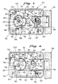
- FIG. 1 is a rear partial sectional view of the lock according to the preferred embodiment of the present invention mounted to a frame element and showing a locking mechanism in a locked condition.
- FIG. 2 is a bottom sectional view of the lock and frame element taken along the section line 2-2 shown in FIG. 1.
- FIG. 3 is a rear sectional view of the lock of FIG. 1 showing activation and the shifted position of a solenoid to engage a lever with a cam wheel slot.
- FIG. 4 is a rear sectional view of the lock of FIG. 1 showing a cam wheel rotated to longitudinally displace the lever and retract the bolt.
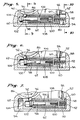
- FIG. 5 is a detailed sectional view of a portion of the lock of FIG. 1 showing the elements of the solenoid in the de-energized configuration.
- FIG. 6 is a detailed sectional view similar to FIG. 5 of a portion of the lock showing the solenoid energized.
- FIG. 7 is a detailed sectional view similar to FIG. 5 of a portion of the lock showing the solenoid energized and shifted to position the lever.
- FIG. 8 is a rear sectional view of a portion of the lock showing one of the steps in the entry of a combination code.
- FIG. 9 is a side sectional view of a portion of the lock taken along the section line 9-9 of FIG. 5 showing the solenoid and a portion of the cam wheel.
- FIG. 10 is a side sectional view of a portion of the lock taken along the section line 10-10 of FIG. 5 showing the solenoid and a detent on the lever received in a recess.
- FIG. 11 is a detailed side section of a portion of the lock of FIG. 1 taken along the section line 11-11 showing a relock mechanism.
- FIG. 12 is a side section similar to FIG. 11 showing the relock engaging the fence lever.
- An exemplary embodiment of the preferred electronic dial combination lock 20 in accordance with the present invention provides a high security lock which minimizes successful tampering, and provides positive engagement of a lever with a cam wheel when a protrusion on the lever is properly aligned with a slot on the cam wheel.
- the lock is preferably mounted on the inside surface of a door 22 or other frame element defining in part the closed or secured location protecting the secured area, such as the contents of a safe.
- the lock 20 keeps the door closed and locked against a frame element 24, which may be, for example, a safe enclosure.
- the lock 20 is contained substantially within a housing 26 mounted on the rear or inside surface of the door 22 by conventional fastening means, such as screws and bosses.
- a cover plate 28 closes the lock housing and is mounted thereto through bolts 30 in a conventional manner.
- the cover plate includes an aperture 32 permitting access to a screw 34.
- a locking mechanism in the form of a bolt 36 is slidably retained in the housing 26 to slide between a locked condition or position shown in FIGS. 1 and 2 and an unlocked condition or position (FIG. 4).
- the bolt slides in an opening in the side of the housing 26 into and out of a receptacle in the frame element 24.
- a pin 38 journaled through a portion of the bolt, interior to the housing 26, moves in a short track defined by a groove 40 formed in the base of the housing to limit the travel of the bolt between the locked position and the unlocked position.
- the pin has a reduced diameter portion 42 which extends to the side of the bolt opposite the groove 40 and into a milled out area 44 of the bolt.
- a lever 46 is pivotably coupled to the bolt through the reduced diameter portion 42 of the pin 38 for controlling the movement of the bolt 36 from the locked position to the unlocked position. Longitudinal movement of the lever within the housing moves the bolt, while rotational movement allows the lever to engage a cam wheel 47, as described more fully below.
- the lever extends from the pivot point at the pin 38 along a neck portion within the lock housing to a nose part 48 for engaging the cam wheel 47.
- the neck of the lever between the nose part and the pivot point includes a relock recess 50 formed in that side of the lever which is adjacent the housing, i.e., closest to the door 22, for receiving the pin of a relock mechanism (described more fully below in conjunction with FIGS. 11 and 12).
- the lever 46 includes a cantilever arm 52 for retaining or holding the lever 46 stationary and out of engagement with the cam wheel 47 when the cantilever arm is stationary and for pivoting the lever arm about the pivot point whenever the end of the cantilever arm is moved.
- the cantilever arm preferably extends from a portion of the lever close to the pivot point between the pivot point and the nose part 48.
- the cantilever arm includes a bore containing a detent pin 54 biased outwardly of the bore by a spring 56 so that the detent pin engages a recess 58 to block movement of the lever 46.
- the recess has a ramp surface 60 and is formed, in the preferred embodiment, integral with one end of a solenoid housing 62 (described more fully below).
- the recess 58 When the recess 58 is maintained in the position shown in FIG. 1, the lever is maintained in a position disengaged from the cam wheel for any rotational position of the cam wheel. Therefore, rotation of the cam wheel while the lever is in the disengaged position will not reveal any information about the configuration of the cam wheel or about the lever position.
- the recess 58 need not be integral with the solenoid housing but may be formed in a separate movable element which, when stationary, will maintain the lever 46 in a disengaged position from the cam wheel 47 for any rotational position of the cam wheel.
- the relative angular position of the cantilever arm is preferably less than 180° but more than 90° from the neck portion of the lever.
- the bolt 36 and the lever 46 are sandwiched between the housing 26 and a metal retaining plate 64.
- An opening in the metal plate accommodates rotation of the cam wheel 47, including the rubber finger used for entering the key code combination.
- a fish paper gasket 66 overlays the metal retaining plate and is coextensive with a printed circuit board 68 so that an appropriate combination code can be entered and received by the printed circuit board and processed in a manner such as that described in U.S. Patent No. 4,745,784.
- the circuits on the printed circuit board are powered by a suitable power source (not shown), such as a replaceable battery as is well known to one skilled in the art.
- the printed circuit board is held in place by a rubber gasket 70 covered by the cover plate 28. Holes are formed in the fish paper gasket 66, the printed circuit board 68 and the rubber gasket 70 to allow free rotation of the cam wheel and the screw 34.
- a shaft or spindle 72 passes through the front of the housing 26 and through a sleeve 74 in the door 22 to extend outwardly of the secured area such that an external shaft end is accessible from outside the secured area while an internal end is within the lock housing.
- the shaft 72 is journaled within the housing for both rotational and axial movement relative to the housing and the printed circuit board 68.
- a dial 76 of well known configuration is mounted to the external end of the shaft and includes a knurled knob 78 for both rotating and axially moving the dial, and therefore the shaft.
- a spring 80 between the door 22 and a recess in the dial biases the dial and shaft outwardly relative to the lock housing 26.
- the portion of the shaft 72 passing through the door 22 is round to permit smooth and reliable rotation of the dial and cam during manipulation of the dial. That portion of the shaft internal to housing 26 and extending a relatively short distance into the door 22 has preferably a square cross-section so that rotation of the shaft through the dial 76 rotates the cam wheel 47.
- the cam wheel 47 is mounted to the square portion of the shaft 72 for coaxial rotation and axial displacement of the cam wheel whenever the shaft is rotated or moved axially.
- the screw 34 fixes the cam wheel on the shaft 72.
- a rubber combination finger 82 is fixed in the cam wheel at an angular position corresponding to one discreet dial and shaft position and at a given radial position relative to the axis of the shaft so as to allow entering of the combination code through appropriate rotation and axial movement of the cam wheel, as described more fully in U.S. Patent No. 4,745,784.
- the cam wheel 47 has two circumferential operating surfaces, located axially on the cam wheel adjacent one another.
- the rear-most operating surface of the cam wheel is located in the same plane as the nose part 48 of the lever 46 and will be termed the lever cam surface 84.
- the axially next adjacent cam surface will be termed the solenoid cam surface 86 for moving the solenoid housing, as described more fully below.
- the lever cam surface 84 includes a gate or slot 88 to accept the nose part 48 of the lever such that upon rotation of the cam wheel by the dial 76 in the proper direction, the lever retracts the bolt 36 to unlock the lock.
- the lever cam surface also includes a slight outward bulge in the form of a lever lift cam 90 positioned, on the lever cam surface, counterclockwise from the slot 88, as viewed in FIG. 1 from the back of the lock, to insure that the nose part 48 of the lever is properly spaced from the cam wheel 47 when the locking mechanism is moved to the locked position.
- the solenoid cam surface 86 is generally circular in outline having a normal diameter less than the normal diameter of the lever cam surface 84.
- the solenoid cam surface includes a small sloped protrusion or boss 92 extending radially outwardly of the solenoid cam surface and extending axially across substantially the entire solenoid cam surface 86 for engaging and pushing an extended detent in the solenoid housing 62 upon rotation of the cam wheel.
- the point of the boss 92 extends approximately to the same maximum radius as the maximum radius of the adjacent portion of the lever cam surface 84.
- the solenoid housing 62 is a rigid body, preferably brass, movable in a channel 94 (FIGS. 3 and 4) for positively driving or moving the lever from its disengaged position to a position for engaging the nose part 48 on the lever 46 with the slot 88 on the cam wheel 47 in response to dial 76 rotation after the combination code has been entered so that rotation of the cam wheel in a given direction changes the locking mechanism from the locked position (FIG. 3) to the unlocked position (FIG. 4).
- the solenoid housing 62 is preferably substantially square in transverse outline (FIGS. 9 and 10) and is slidable in the channel 94.
- the solenoid housing is closed at the left end and includes a circular hole opening at the top of the housing for holding and guiding a spherical detent 96 which can extend or protrude outwardly of the solenoid housing to a detented position (FIGS. 6 and 7) upon actuation of the solenoid to allow the boss 92 to engage the extended detent and move the solenoid housing from left to right, as viewed in FIGS. 5-7.
- the detent 96 When the solenoid is not energized and the detent 96 is unextended, the detent 96 is supported below the opening by the shaft of a solenoid plunger 98.
- the plunger 98 is normally biased to the left (as viewed in FIG. 5) by a spring 100 biasing the plunger from the right end of the plunger.
- the unenergized configuration of the solenoid is shown in FIG. 5.
- the left end of the plunger includes a frustoconical section 102 having a sloped surface to allow the spherical detent 96, (upon actuation of the solenoid), to ride up the sloped surface and onto a cylindrical surface 104 at the end of the plunger so that the detent 96 protrudes from the solenoid housing and can then be engaged by the boss 92.
- the shaft of the plunger is supported and guided by a spool 106, which in turn is supported by the walls of the solenoid housing.
- the spool supports a coil 108 which actuates the solenoid plunger when the correct combination code is entered into the printed circuit board and an appropriate signal is produced from an output on the printed circuit board to the coil 108 in the solenoid, as would be known to one skilled in the art.
- the electrical connection between the output from the printed circuit board and the solenoid coil is conventional and not shown.
- An end cap or cup 110 closes the end of the solenoid housing to retain the plunger, spool and coil in place in the solenoid housing.
- the base of the cup contacting the flanges of the spool 106 supports the plunger spring 100 and stops the right-ward travel of the plunger when the solenoid is actuated.
- the cup incudes an interior cavity opening to the right outside end of the solenoid housing for accepting a compression spring 112 for biasing the entire solenoid housing in a direction to the left as viewed in FIGS. 5-7.
- a relock 114 (FIGS. 11 and 12) is mounted in and biased outwardly of a cavity in the lock housing 26.
- the relock is biased outwardly of the cavity by a relock spring 116 for relocking the lever 46 in the disengaged position (as viewed in FIG. 1) by means of a boss 118 on the relock entering the relock recess 50 in the neck of the lever 46.
- the relock is normally held in the retracted position by the metal retaining plate 64 when the retaining plate, fish paper gasket, printed circuit board, rubber gasket and the cover plate 28 are properly installed.
- the relock is pushed outwardly by the relock spring 116 to lock the lever in the disengaged position if the metal retaining plate 64 is ever moved, for example, by tampering with the shaft 72.
- the bolt 36 is normally in the locked position, the solenoid is de-energized and the dial, shaft and cam wheel are freely rotatable and axially movable.
- the cam wheel does not engage significantly either the lever 46 or the solenoid housing 62, and the lever 46 is maintained in a position substantially disengaged from the cam wheel regardless of the rotational position of the cam wheel.
- the solenoid housing 62 is at its left-most position, and the pin 54 of the lever arm engages the recess 58.
- the solenoid plunger 98 is also in its left-most position, the solenoid being unenergized, and the detent 96 rests on the plunger shaft below the top edge of the solenoid housing.
- the correct combination code can be entered by rotating the cam wheel and moving the cam wheel axially in the proper sequence so that the appropriate pressure pads on the printed circuit board 68 can be actuated by application of pressure through the combination finger 82, as would be understood by one skilled in the art.
- a suitable signal is produced at the output of the printed circuit board to the solenoid to actuate and move the plunger 98 to its right-most position.
- the solenoid As the solenoid is actuated, the plunger moves to the right under control of the coil 108 so that the spherical detent 96 rides up the frustoconical section 102 and onto the cylindrical portion 104 of the plunger.
- the spherical detent is then exposed above the top of the solenoid housing 62 so that it can be engaged by the boss 92 on the solenoid cam surface 86 of the cam wheel 47.
- the condition of the solenoid in the actuated state is shown in FIG. 6. At that point, the cam wheel may be in any rotational position, and the lever is still maintained in its disengaged position.
- the solenoid housing is also still in its left-most position in the channel 94.
- the dial can be turned clockwise (counterclockwise as viewed from the back of the lock housing) until the boss 92 engages the spherical detent 96.
- the boss 92 pushes the spherical detent 96 and therefore the solenoid housing along the channel 94 against the bias of spring 112. Movement of the solenoid housing also moves the recess 58 which holds the detent pin 54.
- the initial movement of the solenoid housing causes the pin 54 in the cantilever arm 52 to move so that the lever pivots until the nose part 48 engages the slot 88 on the cam wheel.
- the boss 92 on the solenoid cam surface 86 and the slot 88 on the lever cam surface 84 are positioned angularly relative to each other such that the nose part of the lever and the slot 88 are aligned for engagement as the boss 92 pushes the spherical detent 96.
- continued translation of the solenoid housing in the channel 94 causes the pin 54 in the cantilever arm 52 of the lever to ride up the ramp surface 60 and onto the outside of the solenoid housing so that the pin can freely move along the solenoid housing as the bolt is retracted by further rotation of the cam wheel.
- FIG. 3 The position of the pin 54 relative to the ramp 60 when the solenoid housing has reached the right-most extent of its travel in the channel 94 is shown in FIG. 3.
- the lever 46 has fully engaged the gate in the cam wheel 47 such that further rotation of the cam wheel moves the lever longitudinally and so that the bolt 36 can be moved from the locked position shown in FIG. 3 to the unlocked position shown in FIG. 4.
- the pin 54 can slide relative to the solenoid housing both as the bolt moves from the locked to the unlocked position and as the solenoid housing returns to its left-most position in the channel 94 as the solenoid becomes de-energized.
- the door can then be opened.
- the dial When the door is thereafter closed and the lock is to be moved back to its locked condition, the dial can be turned in the opposition direction so that the gate pushes the nose part 48 back in the opposite direction to return the bolt to its locked position. Any tendency of the lever to disengage from the gate is prevented by a bearing surface 120 formed in the housing (FIG. 4).
- the lever disengages from the gate and the lever lift cam 90 lifts the end of the lever into the recess in the housing between the bearing surface 120 and the relock 114 (FIG. 1), thereby properly positioning the lever in its disengaged position and the pin 54 in the recess 58.
- the lever lift cam 90 may still touch the nose part 48 of the lever 46 but this possible contact is not considered substantial.
Abstract
Description
- This invention relates generally to electronic dial combination locks having improved tamper resistance, and more specifically to such locks wherein a locking mechanism is opened by rotation of the dial.
- Electronic dial combination locks allow authorized personnel to access otherwise inaccessible security regions such as safes, lock boxes, storage rooms and the like. One such class of lock is the electronic dial combination lock which uses a dial having divisions to enter a combination code to gain entrance to the secured area. The lock has a spindle journaled within the lock for both rotational and axial movement to cause a push pin located on an internal cam wheel to engage one of a plurality of pressure-sensitive switches within the lock located in an evenly-spaced circular pattern centered on the shaft's axis, each switch being capable of making a discrete, unique electrical connection. A circuit contained in the secured region senses the electrical connections and detects when a given subset of connections has been made corresponding to the lock's combination and initiates an electrical signal within the secured region. The signal may be used, e.g., to operate a solenoid to permit a conventional fence lever to engage the cam wheel such that a bolt within the lock may be withdrawn, such as in a safe door. Such a lock is shown and described in U.S. Patent No. 4,745,784. In the lock of that patent, when the correct combination is entered, the solenoid releases a fence lever so that a nose part formed thereon falls by gravity onto the circumferential surface of a cam wheel. The cam wheel is rotated by the combination dial until the nose part on the fence lever engages the slot in the circumference of the cam wheel to allow withdrawal of the bolt in the locking mechanism.
- It has been recognized heretofore that it would be desirable to have a positive drive of the fence toward the tumbler wheel gates and the lever nose toward its cam wheel slot to ensure operation of the lever on entry of the combination. Generally these locks have employed a cam mechanism operated off of dial rotation to drive its fence lever toward the wheel once on each rotation of the dial. Such a lock is illustrated in U.S. Patent No. 4,910,981. However, there is the possibility of learning something about the lock's internal parts from such regular impacting of the wheel by its fence or unauthorized manipulation of the lock by lock experts.
- There is thus a need for a dial combination lock which does not allow an unauthorized user to obtain information about the characteristics of the gate tumbler wheels or the slotted cam wheel through manipulation of the combination dial and fence lever. Additionally, there is a need for a combination lock which prevents engagement of the fence lever with the tumbler wheels or the cam wheel until such time as the correct combination has been dialed into the lock mechanism and the nose part on the lever is aligned with the slot on the cam wheel. There is also a need for a combination lock which provides for positive movement of the lever into engagement with the slot in the cam wheel upon alignment through rotation of the combination dial.
- It is an object of the present invention to provide a high security electronic dial combination lock which provides improved means for minimizing tampering, and to provide more predictable operation of the lock by positively engaging the fence lever with the cam wheel when the nose part on the fence lever and the slot in the cam wheel are properly aligned.
- According to the invention, there is provided an electronically operated lock having a bolt, a dial, a dial operated cam, a bolt operating lever manipulated by engagement with the dial operated cam, and a lever retaining device operably connected to the lever and movable between a first position where the lever cannot engage the cam and a second position where the lever engages the cam, the lever retaining device being biased such that the lever is maintained in substantially the first position, characterised by:
- a first engaging element associated with the cam,
- a second engaging element associated with the lever retaining device, and
- a lever operating device adapted to move one of the first and second engaging elements into an orientation where the first and second engaging elements can contact one another, while maintaining the lever retaining device in substantially the first position, in response to an entry of a predetermined combination through rotation of the dial, whereby further rotation of the dial after said first and second engaging elements are in contact with one another will cause the lever retaining device to move to the second position.
- In the preferred embodiment of the invention, the cam comprises a rotatable cam wheel which has a circumferential surface portion defining a slot such that rotation of the cam wheel moves the slot. The bolt operating lever is coupled to the locking mechanism for changing the condition of the locking mechanism from the locked condition to the unlocked condition and is pivotably movable into and out of engagement with the cam wheel. The lever engages the cam wheel such that rotation of the cam wheel changes the condition of the locking mechanism.
- With the lock described herein, the bolt operating lever is maintained in the disengaged position until the proper code is received by the lock. This serves the distinct purposes of ensuring that the lever does not engage the cam wheel until such time as the proper code has been entered and also that the lever is properly aligned with the cam wheel to allow proper engagement therebetween. Therefore, contact between the lever and the cam wheel cannot be used to obtain information about the characteristics of the cam wheel simply by rotating the combination dial. The means for moving the lever from its disengaged position to engage the cam wheel provides positive movement of the lever for engaging the cam wheel so that engagement between the fence lever and the cam wheel is not dependent on the force of gravity.
- In a preferred embodiment, a solenoid is activated upon entry of the proper combination code for moving a detent into position to be contacted by a boss on the cam wheel. Upon contact with the detent, further rotation of the cam wheel moves the entire solenoid housing which in turn moves a cantilevered portion of the lever so that a nose part on the lever properly engages the slot on the cam wheel. The combination of the boss on the cam wheel, the configuration of the solenoid housing and the cantilevered portion of the lever are such that the slot in the cam wheel and the nose part on the lever are properly aligned when the lever is moved into contact with the cam wheel.
- A relock may be included to hold the lever in its disengaged position even after the solenoid or other parts of the lock are disabled or otherwise affected such as by tampering. In such a case, the locking mechanism thereafter cannot be moved into the unlocked condition.
- Skilled practitioners will obtain a more complete understanding of the present invention from a review of the following detailed description of a preferred embodiment, in conjunction with the drawings, of which the following is a brief description.
- FIG. 1 is a rear partial sectional view of the lock according to the preferred embodiment of the present invention mounted to a frame element and showing a locking mechanism in a locked condition.
- FIG. 2 is a bottom sectional view of the lock and frame element taken along the section line 2-2 shown in FIG. 1.
- FIG. 3 is a rear sectional view of the lock of FIG. 1 showing activation and the shifted position of a solenoid to engage a lever with a cam wheel slot.
- FIG. 4 is a rear sectional view of the lock of FIG. 1 showing a cam wheel rotated to longitudinally displace the lever and retract the bolt.
- FIG. 5 is a detailed sectional view of a portion of the lock of FIG. 1 showing the elements of the solenoid in the de-energized configuration.
- FIG. 6 is a detailed sectional view similar to FIG. 5 of a portion of the lock showing the solenoid energized.
- FIG. 7 is a detailed sectional view similar to FIG. 5 of a portion of the lock showing the solenoid energized and shifted to position the lever.
- FIG. 8 is a rear sectional view of a portion of the lock showing one of the steps in the entry of a combination code.
- FIG. 9 is a side sectional view of a portion of the lock taken along the section line 9-9 of FIG. 5 showing the solenoid and a portion of the cam wheel.
- FIG. 10 is a side sectional view of a portion of the lock taken along the section line 10-10 of FIG. 5 showing the solenoid and a detent on the lever received in a recess.
- FIG. 11 is a detailed side section of a portion of the lock of FIG. 1 taken along the section line 11-11 showing a relock mechanism.
- FIG. 12 is a side section similar to FIG. 11 showing the relock engaging the fence lever.
- An exemplary embodiment of the preferred electronic dial combination lock 20 (FIGS. 1 and 2) in accordance with the present invention provides a high security lock which minimizes successful tampering, and provides positive engagement of a lever with a cam wheel when a protrusion on the lever is properly aligned with a slot on the cam wheel. The lock is preferably mounted on the inside surface of a
door 22 or other frame element defining in part the closed or secured location protecting the secured area, such as the contents of a safe. Thelock 20 keeps the door closed and locked against aframe element 24, which may be, for example, a safe enclosure. - The
lock 20 is contained substantially within ahousing 26 mounted on the rear or inside surface of thedoor 22 by conventional fastening means, such as screws and bosses. Acover plate 28 closes the lock housing and is mounted thereto throughbolts 30 in a conventional manner. The cover plate includes anaperture 32 permitting access to ascrew 34. - A locking mechanism in the form of a
bolt 36 is slidably retained in thehousing 26 to slide between a locked condition or position shown in FIGS. 1 and 2 and an unlocked condition or position (FIG. 4). The bolt slides in an opening in the side of thehousing 26 into and out of a receptacle in theframe element 24. Apin 38 journaled through a portion of the bolt, interior to thehousing 26, moves in a short track defined by agroove 40 formed in the base of the housing to limit the travel of the bolt between the locked position and the unlocked position. The pin has a reduceddiameter portion 42 which extends to the side of the bolt opposite thegroove 40 and into a milled outarea 44 of the bolt. - A
lever 46 is pivotably coupled to the bolt through the reduceddiameter portion 42 of thepin 38 for controlling the movement of thebolt 36 from the locked position to the unlocked position. Longitudinal movement of the lever within the housing moves the bolt, while rotational movement allows the lever to engage acam wheel 47, as described more fully below. The lever extends from the pivot point at thepin 38 along a neck portion within the lock housing to anose part 48 for engaging thecam wheel 47. The neck of the lever between the nose part and the pivot point includes arelock recess 50 formed in that side of the lever which is adjacent the housing, i.e., closest to thedoor 22, for receiving the pin of a relock mechanism (described more fully below in conjunction with FIGS. 11 and 12). - The
lever 46 includes acantilever arm 52 for retaining or holding thelever 46 stationary and out of engagement with thecam wheel 47 when the cantilever arm is stationary and for pivoting the lever arm about the pivot point whenever the end of the cantilever arm is moved. The cantilever arm preferably extends from a portion of the lever close to the pivot point between the pivot point and thenose part 48. The cantilever arm includes a bore containing adetent pin 54 biased outwardly of the bore by aspring 56 so that the detent pin engages arecess 58 to block movement of thelever 46. The recess has aramp surface 60 and is formed, in the preferred embodiment, integral with one end of a solenoid housing 62 (described more fully below). When therecess 58 is maintained in the position shown in FIG. 1, the lever is maintained in a position disengaged from the cam wheel for any rotational position of the cam wheel. Therefore, rotation of the cam wheel while the lever is in the disengaged position will not reveal any information about the configuration of the cam wheel or about the lever position. It should be noted that therecess 58 need not be integral with the solenoid housing but may be formed in a separate movable element which, when stationary, will maintain thelever 46 in a disengaged position from thecam wheel 47 for any rotational position of the cam wheel. As can be seen in FIG. 1, the relative angular position of the cantilever arm is preferably less than 180° but more than 90° from the neck portion of the lever. - The
bolt 36 and thelever 46 are sandwiched between thehousing 26 and ametal retaining plate 64. An opening in the metal plate accommodates rotation of thecam wheel 47, including the rubber finger used for entering the key code combination. Afish paper gasket 66 overlays the metal retaining plate and is coextensive with a printedcircuit board 68 so that an appropriate combination code can be entered and received by the printed circuit board and processed in a manner such as that described in U.S. Patent No. 4,745,784. The circuits on the printed circuit board are powered by a suitable power source (not shown), such as a replaceable battery as is well known to one skilled in the art. The printed circuit board is held in place by arubber gasket 70 covered by thecover plate 28. Holes are formed in thefish paper gasket 66, the printedcircuit board 68 and therubber gasket 70 to allow free rotation of the cam wheel and thescrew 34. - A shaft or
spindle 72 passes through the front of thehousing 26 and through asleeve 74 in thedoor 22 to extend outwardly of the secured area such that an external shaft end is accessible from outside the secured area while an internal end is within the lock housing. Theshaft 72 is journaled within the housing for both rotational and axial movement relative to the housing and the printedcircuit board 68. A dial 76 of well known configuration is mounted to the external end of the shaft and includes a knurled knob 78 for both rotating and axially moving the dial, and therefore the shaft. Aspring 80 between thedoor 22 and a recess in the dial biases the dial and shaft outwardly relative to thelock housing 26. - The portion of the
shaft 72 passing through thedoor 22 is round to permit smooth and reliable rotation of the dial and cam during manipulation of the dial. That portion of the shaft internal tohousing 26 and extending a relatively short distance into thedoor 22 has preferably a square cross-section so that rotation of the shaft through the dial 76 rotates thecam wheel 47. Thecam wheel 47 is mounted to the square portion of theshaft 72 for coaxial rotation and axial displacement of the cam wheel whenever the shaft is rotated or moved axially. Thescrew 34 fixes the cam wheel on theshaft 72. Arubber combination finger 82 is fixed in the cam wheel at an angular position corresponding to one discreet dial and shaft position and at a given radial position relative to the axis of the shaft so as to allow entering of the combination code through appropriate rotation and axial movement of the cam wheel, as described more fully in U.S. Patent No. 4,745,784. - The
cam wheel 47 has two circumferential operating surfaces, located axially on the cam wheel adjacent one another. The rear-most operating surface of the cam wheel is located in the same plane as thenose part 48 of thelever 46 and will be termed thelever cam surface 84. The axially next adjacent cam surface will be termed thesolenoid cam surface 86 for moving the solenoid housing, as described more fully below. Thelever cam surface 84 includes a gate orslot 88 to accept thenose part 48 of the lever such that upon rotation of the cam wheel by the dial 76 in the proper direction, the lever retracts thebolt 36 to unlock the lock. The lever cam surface also includes a slight outward bulge in the form of alever lift cam 90 positioned, on the lever cam surface, counterclockwise from theslot 88, as viewed in FIG. 1 from the back of the lock, to insure that thenose part 48 of the lever is properly spaced from thecam wheel 47 when the locking mechanism is moved to the locked position. - The
solenoid cam surface 86 is generally circular in outline having a normal diameter less than the normal diameter of thelever cam surface 84. The solenoid cam surface includes a small sloped protrusion orboss 92 extending radially outwardly of the solenoid cam surface and extending axially across substantially the entiresolenoid cam surface 86 for engaging and pushing an extended detent in thesolenoid housing 62 upon rotation of the cam wheel. The point of theboss 92 extends approximately to the same maximum radius as the maximum radius of the adjacent portion of thelever cam surface 84. - The
solenoid housing 62 is a rigid body, preferably brass, movable in a channel 94 (FIGS. 3 and 4) for positively driving or moving the lever from its disengaged position to a position for engaging thenose part 48 on thelever 46 with theslot 88 on thecam wheel 47 in response to dial 76 rotation after the combination code has been entered so that rotation of the cam wheel in a given direction changes the locking mechanism from the locked position (FIG. 3) to the unlocked position (FIG. 4). - Considering the solenoid in more detail (FIGS. 5-7, 9 and 10), the
solenoid housing 62 is preferably substantially square in transverse outline (FIGS. 9 and 10) and is slidable in thechannel 94. The solenoid housing is closed at the left end and includes a circular hole opening at the top of the housing for holding and guiding aspherical detent 96 which can extend or protrude outwardly of the solenoid housing to a detented position (FIGS. 6 and 7) upon actuation of the solenoid to allow theboss 92 to engage the extended detent and move the solenoid housing from left to right, as viewed in FIGS. 5-7. When the solenoid is not energized and thedetent 96 is unextended, thedetent 96 is supported below the opening by the shaft of asolenoid plunger 98. Theplunger 98 is normally biased to the left (as viewed in FIG. 5) by aspring 100 biasing the plunger from the right end of the plunger. The unenergized configuration of the solenoid is shown in FIG. 5. The left end of the plunger includes afrustoconical section 102 having a sloped surface to allow thespherical detent 96, (upon actuation of the solenoid), to ride up the sloped surface and onto acylindrical surface 104 at the end of the plunger so that thedetent 96 protrudes from the solenoid housing and can then be engaged by theboss 92. - The shaft of the plunger is supported and guided by a
spool 106, which in turn is supported by the walls of the solenoid housing. The spool supports acoil 108 which actuates the solenoid plunger when the correct combination code is entered into the printed circuit board and an appropriate signal is produced from an output on the printed circuit board to thecoil 108 in the solenoid, as would be known to one skilled in the art. The electrical connection between the output from the printed circuit board and the solenoid coil is conventional and not shown. - An end cap or
cup 110 closes the end of the solenoid housing to retain the plunger, spool and coil in place in the solenoid housing. The base of the cup contacting the flanges of thespool 106 supports theplunger spring 100 and stops the right-ward travel of the plunger when the solenoid is actuated. The cup incudes an interior cavity opening to the right outside end of the solenoid housing for accepting acompression spring 112 for biasing the entire solenoid housing in a direction to the left as viewed in FIGS. 5-7. - A relock 114 (FIGS. 11 and 12) is mounted in and biased outwardly of a cavity in the
lock housing 26. The relock is biased outwardly of the cavity by arelock spring 116 for relocking thelever 46 in the disengaged position (as viewed in FIG. 1) by means of aboss 118 on the relock entering therelock recess 50 in the neck of thelever 46. The relock is normally held in the retracted position by themetal retaining plate 64 when the retaining plate, fish paper gasket, printed circuit board, rubber gasket and thecover plate 28 are properly installed. The relock is pushed outwardly by therelock spring 116 to lock the lever in the disengaged position if themetal retaining plate 64 is ever moved, for example, by tampering with theshaft 72. - In operation, the
bolt 36 is normally in the locked position, the solenoid is de-energized and the dial, shaft and cam wheel are freely rotatable and axially movable. The cam wheel does not engage significantly either thelever 46 or thesolenoid housing 62, and thelever 46 is maintained in a position substantially disengaged from the cam wheel regardless of the rotational position of the cam wheel. Thesolenoid housing 62 is at its left-most position, and thepin 54 of the lever arm engages therecess 58. Thesolenoid plunger 98 is also in its left-most position, the solenoid being unenergized, and thedetent 96 rests on the plunger shaft below the top edge of the solenoid housing. - By manipulation of the dial 76, the correct combination code can be entered by rotating the cam wheel and moving the cam wheel axially in the proper sequence so that the appropriate pressure pads on the printed
circuit board 68 can be actuated by application of pressure through thecombination finger 82, as would be understood by one skilled in the art. - Upon entry of the proper code, a suitable signal is produced at the output of the printed circuit board to the solenoid to actuate and move the
plunger 98 to its right-most position. As the solenoid is actuated, the plunger moves to the right under control of thecoil 108 so that thespherical detent 96 rides up thefrustoconical section 102 and onto thecylindrical portion 104 of the plunger. The spherical detent is then exposed above the top of thesolenoid housing 62 so that it can be engaged by theboss 92 on thesolenoid cam surface 86 of thecam wheel 47. The condition of the solenoid in the actuated state is shown in FIG. 6. At that point, the cam wheel may be in any rotational position, and the lever is still maintained in its disengaged position. The solenoid housing is also still in its left-most position in thechannel 94. - After the solenoid is actuated, the dial can be turned clockwise (counterclockwise as viewed from the back of the lock housing) until the
boss 92 engages thespherical detent 96. As the cam wheel continues to rotate, theboss 92 pushes thespherical detent 96 and therefore the solenoid housing along thechannel 94 against the bias ofspring 112. Movement of the solenoid housing also moves therecess 58 which holds thedetent pin 54. The initial movement of the solenoid housing causes thepin 54 in thecantilever arm 52 to move so that the lever pivots until thenose part 48 engages theslot 88 on the cam wheel. Theboss 92 on thesolenoid cam surface 86 and theslot 88 on thelever cam surface 84 are positioned angularly relative to each other such that the nose part of the lever and theslot 88 are aligned for engagement as theboss 92 pushes thespherical detent 96. After thenose part 48 engages theslot 88, continued translation of the solenoid housing in thechannel 94 causes thepin 54 in thecantilever arm 52 of the lever to ride up theramp surface 60 and onto the outside of the solenoid housing so that the pin can freely move along the solenoid housing as the bolt is retracted by further rotation of the cam wheel. - The position of the
pin 54 relative to theramp 60 when the solenoid housing has reached the right-most extent of its travel in thechannel 94 is shown in FIG. 3. Thelever 46 has fully engaged the gate in thecam wheel 47 such that further rotation of the cam wheel moves the lever longitudinally and so that thebolt 36 can be moved from the locked position shown in FIG. 3 to the unlocked position shown in FIG. 4. Simultaneously, thepin 54 can slide relative to the solenoid housing both as the bolt moves from the locked to the unlocked position and as the solenoid housing returns to its left-most position in thechannel 94 as the solenoid becomes de-energized. The door can then be opened. - When the door is thereafter closed and the lock is to be moved back to its locked condition, the dial can be turned in the opposition direction so that the gate pushes the
nose part 48 back in the opposite direction to return the bolt to its locked position. Any tendency of the lever to disengage from the gate is prevented by a bearingsurface 120 formed in the housing (FIG. 4). - As the
cam wheel 47 continues to turn, the lever disengages from the gate and thelever lift cam 90 lifts the end of the lever into the recess in the housing between thebearing surface 120 and the relock 114 (FIG. 1), thereby properly positioning the lever in its disengaged position and thepin 54 in therecess 58. Once thelever 46 has been moved to its disengaged position, thelever lift cam 90 may still touch thenose part 48 of thelever 46 but this possible contact is not considered substantial. - Having described an exemplary embodiment of the electronic dial combination lock in accordance with the present invention, it should now be apparent to those skilled in the art that the invention achieves the various objectives and advantages initially disclosed herein. It should also be understood by those skilled in the art that various modifications, adaptations and alternative embodiments of the lock of the present invention may be made within the scope and spirit of the present invention, which is defined by the following claims.
Claims (8)
- An electronically operated lock having a bolt (36), a dial (76), a dial operated cam (47), a bolt operating lever (46) manipulated by engagement with the dial operated cam, and a lever retaining device (62, 112) operably connected to the lever and movable between a first position where the lever cannot engage the cam and a second position where the lever engages the cam, the lever retaining device being biased such that the lever is maintained in substantially the first position, characterised by:a first engaging element (92) associated with the cam,a second engaging element (96) associated with the lever retaining device, anda lever operating device (98) adapted to move one of the first and second engaging elements into an orientation where the first and second engaging elements can contact one another, while maintaining the lever retaining device in substantially the first position, in response to an entry of a predetermined combination through rotation of the dial, whereby further rotation of the dial after said first (92) and second (96) engaging elements are in contact with one another will cause the lever retaining device (62, 112) to move to the second position.
- The lock of claim 1 wherein the second engaging element comprises a movable projecting element which is capable of projecting a sufficient distance relative to the cam to engage the first engaging element.
- The lock of claim 1 or claim 2 wherein the lever retaining device includes a shaft (62) having a first end associated with the second engaging element and a second end associated with the lever.
- The lock of any of claims 1 to 4 wherein the lever includes a cantilever portion (52) having a spring-biased detent (54) and the lever retaining device includes a recess (58) for receiving the spring biased detent.
- The lock of claim 4 wherein the recess includes a surface defining a ramp (60) to allow the spring-biased detent to travel up the ramp and out of the recess.
- The lock of any of claims 1 to 5 wherein the lever operating device includes an electro-mechanical solenoid.
- The lock of any of claims 1 to 6 wherein the cam further includes a cam slot (88) and rotation of the cam when the first and second engaging elements are in contact with one another moves the lever into engagement with the cam slot.
- The lock of claim 1, wherein the second engaging element (96) is movable between a withdrawn position spaced from the cam (47) to an engagement position relative to the cam (47) such that the first engaging element (92) engages the second engaging element (96) during at least part of the movement of the cam, the second engaging element (96) being positioned substantially at the withdrawn position before entry of the predetermined combination and movable to the engagement position only after entry of the predetermined combination.
Applications Claiming Priority (3)
| Application Number | Priority Date | Filing Date | Title |
|---|---|---|---|
| US07/629,119 US5307656A (en) | 1990-12-17 | 1990-12-17 | High security electronic dial combination lock |
| US629119 | 1990-12-17 | ||
| PCT/US1991/008788 WO1992011430A1 (en) | 1990-12-17 | 1991-11-22 | High security electronic dial combination lock |
Publications (3)
| Publication Number | Publication Date |
|---|---|
| EP0563253A1 EP0563253A1 (en) | 1993-10-06 |
| EP0563253A4 EP0563253A4 (en) | 1994-07-13 |
| EP0563253B1 true EP0563253B1 (en) | 1997-07-09 |
Family
ID=24521655
Family Applications (1)
| Application Number | Title | Priority Date | Filing Date |
|---|---|---|---|
| EP92903007A Expired - Lifetime EP0563253B1 (en) | 1990-12-17 | 1991-11-22 | High security electronic dial combination lock |
Country Status (4)
| Country | Link |
|---|---|
| US (4) | US5307656A (en) |
| EP (1) | EP0563253B1 (en) |
| DE (1) | DE69126794T2 (en) |
| WO (1) | WO1992011430A1 (en) |
Families Citing this family (54)
| Publication number | Priority date | Publication date | Assignee | Title |
|---|---|---|---|---|
| US5307656A (en) * | 1990-12-17 | 1994-05-03 | La Gard, Inc. | High security electronic dial combination lock |
| CA2071577A1 (en) * | 1991-06-21 | 1992-12-22 | Gerald L. Dawson | Electronic combination lock with high security features |
| JPH06229155A (en) * | 1992-01-13 | 1994-08-16 | C & M Technology Inc | Security lock mechanism |
| US5592838A (en) * | 1992-02-20 | 1997-01-14 | Mas-Hamilton Group | Anti-attack interlocks for a combination lock mechanism |
| US5343723A (en) * | 1992-09-03 | 1994-09-06 | Lockmasters, Inc. | Combination lock |
| DE4323493C1 (en) * | 1993-07-14 | 1994-10-27 | Kromer Theodor Gmbh & Co Kg | Number-combination lock with a rotary knob, with a cam disc and with a drop-in lever |
| EP0725877A4 (en) * | 1993-10-29 | 1997-01-02 | Sargent & Greenleaf | Electronic combination lock |
| US5473919A (en) * | 1994-02-28 | 1995-12-12 | Sargent & Greenleaf, Inc. | Manipulation resistant combination lock with magnets |
| GB9405701D0 (en) * | 1994-03-23 | 1994-05-11 | Intelligent Locking Sys Ltd | Improvements in or relating to locks |
| US5678868A (en) * | 1995-11-28 | 1997-10-21 | Williams; Gary Lin | Electronic door locking mechanism |
| JP3781823B2 (en) | 1996-05-27 | 2006-05-31 | シャープ株式会社 | Magneto-optical recording medium and reproducing method thereof |
| US6006561A (en) * | 1997-05-07 | 1999-12-28 | Mas-Hamilton Group, Inc. | Electronic reset for solenoid activated control in an electronic lock |
| US5893283A (en) * | 1997-05-07 | 1999-04-13 | Mas-Hamilton Group | Solenoid controlled bolt control for an electronic lock |
| US6209367B1 (en) | 1997-06-06 | 2001-04-03 | Richard G. Hyatt, Jr. | Electronic cam assembly |
| US6588243B1 (en) | 1997-06-06 | 2003-07-08 | Richard G. Hyatt, Jr. | Electronic cam assembly |
| US6094953A (en) * | 1998-11-10 | 2000-08-01 | Mas-Hamilton Group, Inc. | Electrically controlled slidebolt lock |
| DE19901838A1 (en) * | 1999-01-19 | 2000-07-20 | Winkhaus Fa August | Electromagnetically activatable locking mechanism |
| CA2299921A1 (en) | 1999-03-05 | 2000-09-05 | Strattec Security Corporation | Modular latch apparatus and method |
| US6786070B1 (en) | 1999-03-05 | 2004-09-07 | Sirattec Security Corporation | Latch apparatus and method |
| US6463773B1 (en) * | 1999-03-05 | 2002-10-15 | Strattec Security Corporation | Electronic latch apparatus and method |
| DE20010136U1 (en) * | 2000-06-06 | 2000-09-28 | Chen Yung Yuan | Mechanically and electronically combined combination lock for safes |
| US6575505B1 (en) | 2000-10-25 | 2003-06-10 | Strattec Security Corporation | Latch apparatus and method |
| US6776442B2 (en) | 2001-01-09 | 2004-08-17 | Strattec Security Corporation | Latch apparatus and method |
| US6978644B1 (en) * | 2002-03-05 | 2005-12-27 | Taper William D | Locking mechanism for handcuffs |
| IL154788A (en) * | 2003-03-06 | 2010-12-30 | Goldman Ilan | Electronic locking mechanism and lock containing it |
| US20050278186A1 (en) * | 2004-06-15 | 2005-12-15 | Carlos De La Huerga | Word puzzle assembly and methods related thereto |
| US20050288082A1 (en) * | 2004-06-15 | 2005-12-29 | Carlos De La Huerga | Word puzzle assembly and methods related thereto |
| US7549516B2 (en) * | 2005-02-11 | 2009-06-23 | Honeywell International Inc. | Elevator door interlock |
| CN100439640C (en) * | 2006-05-25 | 2008-12-03 | 张云山 | Electronic remote control anti-theft lock |
| CN101379257B (en) * | 2006-11-09 | 2013-03-20 | 克劳斯·W·加特纳 | Lock component containing rotary stop device and anti-arbitrary-use mechanism |
| PL2115250T3 (en) * | 2007-02-08 | 2014-02-28 | Knock Nlock Ltd | Solenoid-operated electromechanical lock |
| GB0719472D0 (en) * | 2007-10-05 | 2007-11-21 | Total Product Sales Ltd | Safes |
| EP2331780B1 (en) * | 2008-09-05 | 2018-08-22 | Lock II, L.L.C. | High security lock |
| US8635893B2 (en) | 2008-09-05 | 2014-01-28 | Lock II, L.L.C. | High security lock |
| MX2011004254A (en) * | 2008-10-24 | 2011-05-23 | Master Lock Co | Electromechanical locks and latching arrangements. |
| US8093986B2 (en) * | 2009-01-20 | 2012-01-10 | Lock II, L.L.C. | Self-powered electronic lock |
| US8970344B2 (en) * | 2009-07-14 | 2015-03-03 | Compx International Inc. | Method and system for data control in electronic locks |
| US8516864B2 (en) | 2009-09-10 | 2013-08-27 | Compx International Inc. | Electronic latch mechanism |
| US8742889B2 (en) * | 2009-09-29 | 2014-06-03 | Compx International Inc. | Apparatus and method for electronic access control |
| US8424934B2 (en) | 2010-01-27 | 2013-04-23 | Tim Askins | Electromechanical door locks for lifts |
| NZ607522A (en) * | 2010-08-05 | 2015-05-29 | Sargent & Greenleaf | High security lock |
| IT1402462B1 (en) * | 2010-11-03 | 2013-09-13 | Bastianini | ELECTROCOMED LOCK WITH ROTATING ARPION FOR AUTOMATED SLIDING GATES AND COMMAND METHOD OF THE SAME |
| US8495899B2 (en) * | 2011-05-23 | 2013-07-30 | Klaus W. Gartner | Electromechanical lock |
| EP2935732B1 (en) | 2012-12-19 | 2019-06-05 | Lock II, L.L.C. | Device and methods for preventing unwanted access to a locked enclosure |
| WO2015165267A1 (en) * | 2014-04-29 | 2015-11-05 | 闵浩 | Lock input unit and conversion apparatus |
| KR101567246B1 (en) * | 2014-10-17 | 2015-11-06 | 현대자동차주식회사 | Actuator integrated push opener |
| PL226449B1 (en) * | 2014-11-26 | 2017-07-31 | Ryszard Gawerski | Coded lock |
| CN106574468B (en) | 2015-02-09 | 2019-05-10 | 以劳克技术名义代理的Mg 技术中心私营公司 | Electronics and mechanical code lock |
| US9217263B1 (en) * | 2015-03-19 | 2015-12-22 | Getac Technology Corporation | Double-opening lock assembly |
| WO2017058243A1 (en) * | 2015-10-02 | 2017-04-06 | Gartner Klaus W | Dual input lock with removable dial |
| US11846121B2 (en) | 2017-06-02 | 2023-12-19 | Lock Ii, Llc | Device and methods for providing a lock for preventing unwanted access to a locked enclosure |
| US11176765B2 (en) | 2017-08-21 | 2021-11-16 | Compx International Inc. | System and method for combined electronic inventory data and access control |
| US11157789B2 (en) | 2019-02-18 | 2021-10-26 | Compx International Inc. | Medicinal dosage storage and method for combined electronic inventory data and access control |
| US20210372164A1 (en) * | 2020-05-29 | 2021-12-02 | Klaus W. Gartner | Electromechanical lock |
Family Cites Families (36)
| Publication number | Priority date | Publication date | Assignee | Title |
|---|---|---|---|---|
| US686073A (en) * | 1901-03-20 | 1901-11-05 | William H Hollar | Electrically-controlled combination-lock. |
| US1353257A (en) * | 1919-08-29 | 1920-09-21 | Adolph Z Mample | Electric combination-lock |
| US1867001A (en) * | 1929-05-18 | 1932-07-12 | Sargent & Greenleaf | Lock mechanism |
| US2079702A (en) * | 1934-05-15 | 1937-05-11 | Sargent & Greenleaf | Lock mechanism |
| US2775114A (en) * | 1949-01-03 | 1956-12-25 | Cora A Lee | Combination lock |
| US2925726A (en) * | 1951-10-03 | 1960-02-23 | Harry C Miller | Combination lock |
| US3045466A (en) * | 1960-02-08 | 1962-07-24 | Diebold Inc | Manipulation resistive combination lock |
| US3339382A (en) * | 1964-12-15 | 1967-09-05 | Sargent & Greenleaf | Combination lock for security cabinets and the like |
| US3376721A (en) * | 1966-01-05 | 1968-04-09 | Levine Seymour | Electromechanical combination lock |
| US3559430A (en) * | 1968-08-08 | 1971-02-02 | Russell S Waller | Locking mechanism |
| US3702070A (en) * | 1971-02-19 | 1972-11-07 | Klaus W Gartner | Sequential signal producing means |
| US3702551A (en) * | 1971-02-19 | 1972-11-14 | Mosler Safe Co | Time delay combination locks |
| US3758734A (en) * | 1971-05-24 | 1973-09-11 | K Gartner | R means sequential switch means with a linearly movable and rotatable actuato |
| US3980844A (en) * | 1974-04-05 | 1976-09-14 | Bianco Eric L | Combination lock and switch device |
| US3981167A (en) * | 1974-12-05 | 1976-09-21 | Phillips Peter J | Direct-dial combination lock |
| US3968667A (en) * | 1975-07-02 | 1976-07-13 | Sargent & Greenleaf, Inc. | Combination lock construction |
| US4038846A (en) * | 1975-10-24 | 1977-08-02 | Paul Klann | Electronic combination lock |
| US3991596A (en) * | 1976-01-30 | 1976-11-16 | Sargent & Greenleaf, Inc. | Tumbler wheel, changeable combination key lock construction |
| ZA77801B (en) * | 1976-03-11 | 1978-04-26 | Chubb & Sons Lock & Safe Co | Improvements relating to keyless combination locks |
| US4142388A (en) * | 1977-03-30 | 1979-03-06 | Klaus W. Gartner | Tumbler wheels for combination locks |
| US4148092A (en) * | 1977-08-04 | 1979-04-03 | Ricky Martin | Electronic combination door lock with dead bolt sensing means |
| US4328689A (en) * | 1979-12-20 | 1982-05-11 | Hans Keller | Spring bolt combination lock |
| US4541259A (en) * | 1981-08-03 | 1985-09-17 | La Gard, Inc. | Combination lock |
| US4532785A (en) * | 1983-05-19 | 1985-08-06 | La Gard, Inc. | Combination lock |
| US4628715A (en) * | 1985-03-01 | 1986-12-16 | La Gard, Inc. | Tumbler wheel assembly shield for combination locks |
| CH664794A5 (en) * | 1985-03-29 | 1988-03-31 | Relhor Sa | DEVICE FOR LIFTING A CONDITIONAL PROHIBITION OF THE OPERATION OF A LOCK. |
| DE8524683U1 (en) * | 1985-08-29 | 1985-10-31 | Mauer GmbH & Co KG, 5628 Heiligenhaus | Combination lock |
| US4756176A (en) * | 1985-11-30 | 1988-07-12 | La Gard, Inc. | Fence lever control device for a combination lock |
| US4831851A (en) * | 1986-04-10 | 1989-05-23 | Supra Products, Inc. | Combination/electronic lock system |
| US4745784A (en) * | 1986-04-21 | 1988-05-24 | Alan Uyeda | Electronic dial combination lock |
| US4754629A (en) * | 1987-11-10 | 1988-07-05 | Allen Mark L | Safe relocking system |
| DE3817696C1 (en) * | 1988-05-25 | 1989-11-30 | Pierre Dipl.-Ing. 8012 Ottobrunn De Meyers | Coupling system with driving plate, drop-in lever and detent element |
| US4904984A (en) * | 1988-06-10 | 1990-02-27 | Gartner Klaus W | Combination lock with an additional security lock |
| US4967577A (en) * | 1988-06-10 | 1990-11-06 | La Gard, Inc. | Electronic lock with manual combination override |
| US4910981A (en) * | 1989-03-17 | 1990-03-27 | Gartner Klaus W | Automatically locking and tumbler scrambling manipulation proof lock |
| US5307656A (en) * | 1990-12-17 | 1994-05-03 | La Gard, Inc. | High security electronic dial combination lock |
-
1990
- 1990-12-17 US US07/629,119 patent/US5307656A/en not_active Expired - Lifetime
-
1991
- 1991-11-22 EP EP92903007A patent/EP0563253B1/en not_active Expired - Lifetime
- 1991-11-22 WO PCT/US1991/008788 patent/WO1992011430A1/en active IP Right Grant
- 1991-11-22 DE DE69126794T patent/DE69126794T2/en not_active Expired - Fee Related
-
1994
- 1994-05-02 US US08/237,258 patent/US5540068A/en not_active Expired - Fee Related
-
1996
- 1996-06-26 US US08/669,748 patent/US5778711A/en not_active Expired - Fee Related
-
1998
- 1998-07-13 US US09/116,335 patent/US6295849B1/en not_active Expired - Fee Related
Also Published As
| Publication number | Publication date |
|---|---|
| EP0563253A4 (en) | 1994-07-13 |
| DE69126794D1 (en) | 1997-08-14 |
| EP0563253A1 (en) | 1993-10-06 |
| US5540068A (en) | 1996-07-30 |
| WO1992011430A1 (en) | 1992-07-09 |
| US5778711A (en) | 1998-07-14 |
| US6295849B1 (en) | 2001-10-02 |
| US5307656A (en) | 1994-05-03 |
| DE69126794T2 (en) | 1997-11-20 |
Similar Documents
| Publication | Publication Date | Title |
|---|---|---|
| EP0563253B1 (en) | High security electronic dial combination lock | |
| US5887467A (en) | Pawl & solenoid locking mechanism | |
| EP0378557B1 (en) | Battery-powered door lock assembly and method | |
| US6298699B1 (en) | Electronic input and dial entry lock | |
| US4736970A (en) | Electrically controlled door lock | |
| US4312198A (en) | Magnetic key operated hotel door lock | |
| US6718806B2 (en) | Electronic locking system with emergency exit feature | |
| US5033282A (en) | Self-locking electronic lock | |
| US8225629B2 (en) | Portable lock with electronic lock actuator | |
| US5953942A (en) | Catch mechanism for locks | |
| US4125008A (en) | Electrically operated lock | |
| US5845523A (en) | Electronic input and dial entry lock | |
| US10017964B2 (en) | Latch mechanism for an exit device | |
| JPH08135279A (en) | Lock handle device of door used for both right and left hands | |
| US5622067A (en) | User-codable magnetic lock | |
| US2766606A (en) | Combination lock | |
| GB2024924A (en) | Steering column locks | |
| EP4320325A1 (en) | Half-cylinder lock | |
| GB2297354A (en) | An electronic combination lock having a dial-shaped handle with a keypad | |
| JPS6128066B2 (en) | ||
| EP0229514B1 (en) | Lock bolts | |
| US20050179556A1 (en) | Alarm device for pickproofing a lock member | |
| CA1089899A (en) | Actuating mechanism for electrical switches | |
| JPH0213711B2 (en) | ||
| JPS5922216Y2 (en) | Door locking device |
Legal Events
| Date | Code | Title | Description |
|---|---|---|---|
| PUAI | Public reference made under article 153(3) epc to a published international application that has entered the european phase |
Free format text: ORIGINAL CODE: 0009012 |
|
| 17P | Request for examination filed |
Effective date: 19930623 |
|
| AK | Designated contracting states |
Kind code of ref document: A1 Designated state(s): DE FR GB |
|
| RHK1 | Main classification (correction) |
Ipc: E05B 47/06 |
|
| A4 | Supplementary search report drawn up and despatched | ||
| AK | Designated contracting states |
Kind code of ref document: A4 Designated state(s): DE FR GB |
|
| 17Q | First examination report despatched |
Effective date: 19951012 |
|
| GRAG | Despatch of communication of intention to grant |
Free format text: ORIGINAL CODE: EPIDOS AGRA |
|
| GRAH | Despatch of communication of intention to grant a patent |
Free format text: ORIGINAL CODE: EPIDOS IGRA |
|
| GRAH | Despatch of communication of intention to grant a patent |
Free format text: ORIGINAL CODE: EPIDOS IGRA |
|
| GRAA | (expected) grant |
Free format text: ORIGINAL CODE: 0009210 |
|
| AK | Designated contracting states |
Kind code of ref document: B1 Designated state(s): DE FR GB |
|
| REF | Corresponds to: |
Ref document number: 69126794 Country of ref document: DE Date of ref document: 19970814 |
|
| ET | Fr: translation filed | ||
| PLBE | No opposition filed within time limit |
Free format text: ORIGINAL CODE: 0009261 |
|
| STAA | Information on the status of an ep patent application or granted ep patent |
Free format text: STATUS: NO OPPOSITION FILED WITHIN TIME LIMIT |
|
| 26N | No opposition filed | ||
| REG | Reference to a national code |
Ref country code: GB Ref legal event code: IF02 |
|
| PGFP | Annual fee paid to national office [announced via postgrant information from national office to epo] |
Ref country code: GB Payment date: 20021122 Year of fee payment: 12 |
|
| PGFP | Annual fee paid to national office [announced via postgrant information from national office to epo] |
Ref country code: DE Payment date: 20021125 Year of fee payment: 12 |
|
| PGFP | Annual fee paid to national office [announced via postgrant information from national office to epo] |
Ref country code: FR Payment date: 20021227 Year of fee payment: 12 |
|
| PG25 | Lapsed in a contracting state [announced via postgrant information from national office to epo] |
Ref country code: GB Free format text: LAPSE BECAUSE OF NON-PAYMENT OF DUE FEES Effective date: 20031122 |
|
| PG25 | Lapsed in a contracting state [announced via postgrant information from national office to epo] |
Ref country code: DE Free format text: LAPSE BECAUSE OF NON-PAYMENT OF DUE FEES Effective date: 20040602 |
|
| GBPC | Gb: european patent ceased through non-payment of renewal fee |
Effective date: 20031122 |
|
| PG25 | Lapsed in a contracting state [announced via postgrant information from national office to epo] |
Ref country code: FR Free format text: LAPSE BECAUSE OF NON-PAYMENT OF DUE FEES Effective date: 20040730 |
|
| REG | Reference to a national code |
Ref country code: FR Ref legal event code: ST |