EP0538207A2 - Multi-function pipe bending machine - Google Patents
Multi-function pipe bending machine Download PDFInfo
- Publication number
- EP0538207A2 EP0538207A2 EP92830565A EP92830565A EP0538207A2 EP 0538207 A2 EP0538207 A2 EP 0538207A2 EP 92830565 A EP92830565 A EP 92830565A EP 92830565 A EP92830565 A EP 92830565A EP 0538207 A2 EP0538207 A2 EP 0538207A2
- Authority
- EP
- European Patent Office
- Prior art keywords
- pipe
- bending
- slide
- support body
- die
- Prior art date
- Legal status (The legal status is an assumption and is not a legal conclusion. Google has not performed a legal analysis and makes no representation as to the accuracy of the status listed.)
- Granted
Links
Images


Classifications
-
- B—PERFORMING OPERATIONS; TRANSPORTING
- B21—MECHANICAL METAL-WORKING WITHOUT ESSENTIALLY REMOVING MATERIAL; PUNCHING METAL
- B21D—WORKING OR PROCESSING OF SHEET METAL OR METAL TUBES, RODS OR PROFILES WITHOUT ESSENTIALLY REMOVING MATERIAL; PUNCHING METAL
- B21D7/00—Bending rods, profiles, or tubes
- B21D7/02—Bending rods, profiles, or tubes over a stationary forming member; by use of a swinging forming member or abutment
- B21D7/021—Construction of forming members having more than one groove
Landscapes
- Engineering & Computer Science (AREA)
- Mechanical Engineering (AREA)
- Bending Of Plates, Rods, And Pipes (AREA)
Abstract
Description
- The present invention relates to a multi-function pipe bending machine.
- It is known that in many types of applications the formation along the same pipe of several bendings which are close to each other and oriented in opposite directions is often required, which means that it is for example necessary first to execute a bending to the right in a pipe length, and then a bending to the left in another length of the same pipe, the second bending being close to the first one.
- In other cases bendings in succession are to be carried out in separate planes, for example in planes perpendicular to each other. In the known art, such bendings are achieved through the sequential use of one pipe bending machine for carrying out the bending to the right for example, and a second pipe bending machine for executing the left bending.
- In fact, if one would try to use the same machine for carrying out a bending in the opposite way with respect to the one provided by the machine, once the first bending has been executed he would be obliged to rotate the pipe. But this operation will be generally impossible when bendings are very close to each other because the pipe portion that has been already bent would interfere with the bending head. It is therefore absolutely necessary to remove the pipe from the first pipe bending machine, carry it to the second pipe bending machine and make all operations necessary for placement and mounting of the pipe to the second machine.
- The operation steps briefly described above involve important downtime and production slowing down that give rise to an increase in the production costs when several bendings in opposite ways are necessary.
- Attempts have been made to solve the above drawbacks by using bending heads equipped with a double locking arrangement available at two positions rotated through 180° from each other so that the bending to the right could be first carried out and subsequently the bending to the left. However these attemps have not been successful too, because in this solution important downtime periods during which the production operations are stopped are required for disassembling the head and carrying out its rotation.
- In addition pipe bending machines of known type often do not allow the bending dies, that is the shaped components to which pipe is forcedly made to adhere so that it may be suitably bent, to be easily replaced. In fact it is necessary to completely remove the pipe, replace the die and set the pipe in place again.
- In addition, often a reduced range of different dies can be used on a single because the distance between the positioning axis of the pipe and the engagement pin of the die is fixed. As a consequence, for a given outer diameter of the pipe, there is only one bending radius in each machine according to which the same pipe can be bent.
- Under this situation, the technical task underlying the present invention is to devise a multi-function pipe bending machine capable of substantially eliminating the above drawbacks.
- Within the scope of this technical task it is an important object of the invention to devise a multi-function pipe bending machine enabling bendings of pipes oriented in opposite ways and lying in different planes to be easily and readily carried out.
- Another important object of the invention is to provide a pipe bending machine enabling a wide variety of bending dies to be used so that bendings even of different radii along one and the same pipe can be easily and readily made.
- A further object of the invention is to device a pipe bending machine enabling a self-governing and automatic loading of the pipes without resorting to external manual interventions or to automatic handlers (robots).
- The technical task mentioned and the objects specified are substantially attained by a multi-function pipe bending machine comprising:
- a base structure,
- at least one bending die,
- at least one unit for positioning and locking a pipe to be bent against said bending die,
- a rotatably movable bending device active on said pipe against the action of said die,
characterized in that it comprises: - one support body slidably engaged to said base structure along one traverse direction,
- first actuation means for diplacing said first support body,
- a second support slidably engaged to said first body along a traverse direction perpendicular to said first traverse direction, and
- second actuation means for displacing said second support body,
- said bending die, positioning and locking unit and bending device being engaged to said second support body.
- A preferred embodiment of multi-function pipe bending machine in accordance with the present invention will be now described by way of non-limiting example with reference to the accompanying drawings, in which:
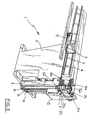
- Fig. 1 is a perspective view of a machine in accordance with the invention during an initial work step;
- Fig. 2 shows the machine of Fig. 1 while a first bending is being carried out; and
- Fig. 3 shows the machine of Fig. 1 as set for the formation of a second bending.
- Referring to the drawings, the multi-function pipe bending machine of the invention has been generally identified by
reference numeral 1. - It comprises a
base structure 2 to which, in a conventional and known manner, acarrage 3 horizontally movable onslide rails 4 is engaged. Provided on said carriage are members 5 (partly shown in the figures) designed to support, rotate and lock apipe 6 to be bent. - In an original manner, as clearly viewed from the figures, the
carriage 3 and the supportedpipe 6 are disposed in cantilevered fashion on one side of thebase structure 2. - Engaged at the end of the
base structure 2 is abending head 7 comprising one support body defined by aslide 8 movable on first guides 9 integral to thebase structure 2 and oriented horizontally along one traverse direction. - Slidably engaged to the
first slide 8 by means ofsecond guides 10 integral to the first slide itself and oriented vertically along a second traverse direction perpendicular to said first direction, is a second support body defined by asecond slide 11. - The first and second slides, 8 and 11, are driven in motion along the respective guides by actuation means for example comprising the electric motors and first and second operating screws, 12 and 13, oriented parallelly to the first guides 9 and
second guides 10, respectively. - Two bending dies 14a and 14b can be positioned on the
second slide 11. They are disposed spaced apart from each other in superposed relationship. Therefore an upper die 14a and alower die 14b are available and they can be used selectively depending on working requirements. - Two
units 15a and 15b for positioning and locking thepipe 6 to be bent are provided in the vicinity of said dies. They are comprised respectively of an upper jaw 16a set in motion by an upper fluid-operated locking cylinder 17a and a lower jaw 16b set in motion by a lower fluid-operated locking cylinder 17b (Fig. 2). - Provision is finally made for a
bending device 18 rotatably movable about an axis coincident with the positioning axis of thedies 14a and 14b and comprising an upper pusher 19a and alower pusher 19b, actuated by an upper fluid-operated bending cylinder 20a and a lower fluid-operated bending cylinder 20b and active on thepipe 6 against the action ofdies 14a and 14b. - Operation of the multi-function pipe bending machine described above mainly as regards structure, is a follows.
- After positioning the
pipe 6 on the support and locking means 5, the upper jaw 16a for example locks the pipe agaisnt the upper die 14a. Thebending device 18 by rotating and pressing thepipe 6 by means of the upper pusher 19a, carries out one bending according to the intended angle (see Fig. 2). - If for instance a second bending is required in the same pipe at a short distance from the first one and in a plane perpendicular to the plane in which the first bending has been executed thereby involving a downward rotation of the carried out bending, after bringing the
bending device 18 back to its starting position, in accordance with the working cycle it is now necessary to unlock the pipe both by acting on the upper fluid-operated cylinders 17a and 20a, and by initiating a displacement of thefirst slide 8 so as to get thepipe 6 free from the die groove. - Subsequently, appropriate movements of both the
second slide 11 in the vertical direction and thefirst slide 8 in the horizontal direction combined with the progress ofpipe 6 along its axis and its rotation through 90°, allow thelower die 14b to be positioned in register with the pipe portion along which a second bending is intended to be formed (see Fig. 3). - In greater detail, for changing from the pipe arrangement shown in Fig. 2 to the pipe arrangement shown in Fig. 3, once the pipe being worked has been unlocked, the
second slide 11 is caused to move downwardly, thefirst slide 8 being subsequently displaced to the right with reference to the drawings. - Afterwards, the
second slide 11 is brought upwardly while thefirst slide 8 is caused to slide to the left so as to bring the bending head in register with the pipe to be bent. - Finally the
second slide 11 is slightly moved down again in order to place thelower die 14b in an operating positioning close to the pipe to be bent. - It is noted that in case shown in the figures the use of the lower die together with the side arrangement in cantilevered fashion of the
carriage 3 enables interference to be avoided between the first pipe length already submitted to bending and some components of thebending head 7. - Should other types of bendings be desired, for example first one bending to the right and then one bending to the left, the movement possibilities offered by
slides device 18 to be disengaged from the first location and correctly placed for executing the following bending, while at the same time avoiding interferences with the pipe submitted to bending. - In addition it is pointed out that on pipe bending machines in accordance with the invention dies having different bending diameters can be used. In fact, the displacements of the
bending head 7 permit the distance between the center of each die and the longitudinal pipe axis to be properly adjusted. Consequently, for pipes having the same diameter it is possible to use several different dies which are interchangeable with each other so as to achieve bendings of different bending radius. - It is also to be noted that since the pipe bending machine of the invention has gripping members that are made movable in space by
slides locking elements 5. In this way the use of additional devices such as manipulators or robots for making the pipe supply steps automatic, can be avoided. - Likewise, the crossed movement in the horizontal and vertical directions of
slides - Another opportunity offered by the presence of
slides - Modifications and variations may be made to the machine as conceived, all of them falling within the scope of the invention as claimed in the following claims.
Claims (4)
- A multi-function pipe bending machine (1) comprising:- a base structure (2),- at least one bending die (7),- at least one unit (15a, 15b) for positioning and locking a pipe (6) to be sent against said bending die,- a rotatably movable bending device (18) active on said pipe (6) against the action of said die
characterized in that it comprises:- one support body (8) slidably engaged to said base structure (2) along one travers direction,- first actuation means (12) for displacing said first support body,- a second support body (11) slidably engaged to said first body along a traverse direction perpendicular to said first traverse direction, and- second actuation means (13) for displacing said second support body,- said bending die, positioning and locking unit and bending device being engaged to said second support body. - A pipe bending machine according to claim 1, characterized in that said first support body is defined by one slide (8) engaged to first guides (9) integral to said base structure and in that said second support body is defined by a second slide (11) engaged to second guides (10) integral to said first slide.
- A machine according to claim 1, characterized in that said first and second actuation means comprises first and second operating screws (12, 13) active on said first and second support bodies (8, 11), respectively.
- A machine according to claim 1, characterized in that two of said bending dies (14a, 14b) are provided which are disposed spaced apart from each other in superposed relationship and in that for each of said dies provision is made for a unit (15a, 15b) for positioning and locking said pipe (6), which pipe is disposed in cantilevered fashion and is movable along one side of the base structure.
Applications Claiming Priority (2)
| Application Number | Priority Date | Filing Date | Title |
|---|---|---|---|
| ITMI912737A IT1251934B (en) | 1991-10-16 | 1991-10-16 | MULTIPURPOSE PIPE BENDING MACHINE |
| ITMI912737 | 1991-10-16 |
Publications (3)
| Publication Number | Publication Date |
|---|---|
| EP0538207A2 true EP0538207A2 (en) | 1993-04-21 |
| EP0538207A3 EP0538207A3 (en) | 1993-06-30 |
| EP0538207B1 EP0538207B1 (en) | 1995-05-24 |
Family
ID=11360877
Family Applications (1)
| Application Number | Title | Priority Date | Filing Date |
|---|---|---|---|
| EP92830565A Expired - Lifetime EP0538207B1 (en) | 1991-10-16 | 1992-10-13 | Multi-function pipe bending machine |
Country Status (5)
| Country | Link |
|---|---|
| US (1) | US5263350A (en) |
| EP (1) | EP0538207B1 (en) |
| DE (1) | DE69202678T2 (en) |
| ES (1) | ES2072742T3 (en) |
| IT (1) | IT1251934B (en) |
Cited By (8)
| Publication number | Priority date | Publication date | Assignee | Title |
|---|---|---|---|---|
| FR2758281A1 (en) * | 1997-01-14 | 1998-07-17 | Robolix Sa | MACHINE FOR BENDING LOW DIAMETER TUBES, IN PARTICULAR LESS THAN 10MM, PRECUT AND PRESENTING CONNECTION SYSTEMS AT EACH OF THEIR ENDS, AND BENDING HEAD FOR SUCH A MACHINE |
| EP0990471A1 (en) * | 1998-09-30 | 2000-04-05 | FABBRICA MACCHINE CURVATUBI CRIPPA AGOSTINO S.p.A. | Bending machine |
| WO2000018527A1 (en) * | 1998-09-25 | 2000-04-06 | Pulzer Biegetechnik Gmbh | Pressure pad device for a bending machine |
| EP1291094A1 (en) * | 2001-10-02 | 2003-03-12 | FABBRICA MACCHINE CURVATUBI CRIPPA AGOSTINO S.p.A. | Draw-bending machine |
| EP1396295A1 (en) * | 2002-09-05 | 2004-03-10 | Trumpf Rohrtechnik GmbH + Co. KG | Bending machine with bending tools at opposite sides of a tool carrier |
| EP1396294A1 (en) * | 2002-09-05 | 2004-03-10 | Trumpf Rohrtechnik GmbH + Co. KG | Bending machine with bending tools at opposite sides of a tool carrier |
| US6715328B2 (en) * | 1998-09-25 | 2004-04-06 | Trumpf Pulzer Gmbh +Co. Kg | Bracing device for a bending machine |
| EP1914021A1 (en) | 2006-10-21 | 2008-04-23 | Felss Burger GmbH | Device for bending bars and/or rod shaped workpieces, in particular pipes, and bending tool for this device |
Families Citing this family (14)
| Publication number | Priority date | Publication date | Assignee | Title |
|---|---|---|---|---|
| IT1290141B1 (en) * | 1997-03-21 | 1998-10-19 | Blm Spa | MACHINE TO CURVE FILIFORM MATERIALS SUCH AS BAR TUBES OR PROFILES |
| US7131312B2 (en) * | 2000-12-25 | 2006-11-07 | Yamaha Hatsudoki Kabushiki Kaisha | Pipe bending apparatus and method |
| US6655183B1 (en) * | 2002-07-16 | 2003-12-02 | Chiao Sheng Machinery Co., Ltd. | Lifting mechanism for a head member of a pipe bender |
| EP1459816B1 (en) * | 2003-03-15 | 2006-09-06 | Trumpf Werkzeugmaschinen GmbH + Co. KG | Bending device with multi-level bending tool, clamping jaw unit and sliding support unit for such a bending device |
| US7021102B2 (en) * | 2003-03-15 | 2006-04-04 | Trumpf Rohrtechnik Gmbh + Co. Kg | Bending machine with bending tools on opposite sides of a tool platen |
| TWI243723B (en) * | 2004-06-08 | 2005-11-21 | Ying Lin Machine Ind Co Ltd | Dual-directional pipe-bending machine |
| US7254972B1 (en) * | 2006-06-28 | 2007-08-14 | Chia Sheng Machinery Co., Ltd. | Moving mold mechanism of a pipe bending machine |
| DE102008047542C5 (en) * | 2008-09-16 | 2016-02-18 | Tracto-Technik Gmbh & Co. Kg | Tube bending machine |
| PT3027334T (en) * | 2013-08-01 | 2018-06-06 | Addisonmckee Inc | Tie bar tensioning system |
| JP1525573S (en) * | 2014-11-26 | 2017-05-22 | ||
| JP1525570S (en) * | 2014-11-26 | 2017-05-22 | ||
| JP1525574S (en) * | 2014-11-26 | 2017-05-22 | ||
| JP1527322S (en) * | 2014-11-26 | 2017-06-05 | ||
| JP1525571S (en) * | 2014-11-26 | 2017-05-22 |
Citations (6)
| Publication number | Priority date | Publication date | Assignee | Title |
|---|---|---|---|---|
| US3017917A (en) * | 1959-12-10 | 1962-01-23 | Pines Engineering Co Inc | Tube bending machine |
| FR2530980A1 (en) * | 1982-08-02 | 1984-02-03 | Eaton Leonard Corp | BENDER WITH MULTIPLE CURVES |
| JPS61259836A (en) * | 1985-05-14 | 1986-11-18 | Ishikawajima Harima Heavy Ind Co Ltd | Bending device for tube |
| WO1987000775A1 (en) * | 1985-08-05 | 1987-02-12 | Gardner R F | Pipe bending machine |
| DE3644251A1 (en) * | 1986-05-31 | 1987-12-03 | Chuo Denki Seisakusho | BENDING MACHINE |
| EP0446819A2 (en) * | 1990-03-13 | 1991-09-18 | Mewag Maschinenfabrik Ag | Tube bending machine |
Family Cites Families (7)
| Publication number | Priority date | Publication date | Assignee | Title |
|---|---|---|---|---|
| US3299681A (en) * | 1960-03-22 | 1967-01-24 | Baldwin Lima Hamilton Corp | Program controlled tube bender |
| US3147792A (en) * | 1961-09-25 | 1964-09-08 | Charles F Hautau | Tube and bar bending machinery |
| US4112728A (en) * | 1975-08-22 | 1978-09-12 | Deutsche Babcock Aktiengesellschaft | Device for bending pipes |
| US5010758A (en) * | 1984-03-23 | 1991-04-30 | Chiyoda Kogyo Co., Ltd. | Bending machine |
| GB2187666B (en) * | 1986-03-15 | 1989-12-20 | Pressbend Ltd | Pipe bending apparatus |
| DE3618701A1 (en) * | 1986-06-04 | 1987-12-10 | Spaeth Gmbh & Co Kg Stahlbau B | METHOD AND DEVICE FOR COLD FORMING PROFILES FROM IRON AND NON-FERROUS METALS |
| CA1317868C (en) * | 1989-10-05 | 1993-05-18 | Hideyuki Togoshi | Bending machine |
-
1991
- 1991-10-16 IT ITMI912737A patent/IT1251934B/en active IP Right Grant
-
1992
- 1992-10-13 EP EP92830565A patent/EP0538207B1/en not_active Expired - Lifetime
- 1992-10-13 US US07/960,009 patent/US5263350A/en not_active Expired - Lifetime
- 1992-10-13 DE DE69202678T patent/DE69202678T2/en not_active Expired - Lifetime
- 1992-10-13 ES ES92830565T patent/ES2072742T3/en not_active Expired - Lifetime
Patent Citations (6)
| Publication number | Priority date | Publication date | Assignee | Title |
|---|---|---|---|---|
| US3017917A (en) * | 1959-12-10 | 1962-01-23 | Pines Engineering Co Inc | Tube bending machine |
| FR2530980A1 (en) * | 1982-08-02 | 1984-02-03 | Eaton Leonard Corp | BENDER WITH MULTIPLE CURVES |
| JPS61259836A (en) * | 1985-05-14 | 1986-11-18 | Ishikawajima Harima Heavy Ind Co Ltd | Bending device for tube |
| WO1987000775A1 (en) * | 1985-08-05 | 1987-02-12 | Gardner R F | Pipe bending machine |
| DE3644251A1 (en) * | 1986-05-31 | 1987-12-03 | Chuo Denki Seisakusho | BENDING MACHINE |
| EP0446819A2 (en) * | 1990-03-13 | 1991-09-18 | Mewag Maschinenfabrik Ag | Tube bending machine |
Non-Patent Citations (1)
| Title |
|---|
| PATENT ABSTRACTS OF JAPAN vol. 11, no. 114 (M-579)(2561) 10 April 1987 & JP-A-61 259 836 ( ISHIKAWAJIMA ) * |
Cited By (11)
| Publication number | Priority date | Publication date | Assignee | Title |
|---|---|---|---|---|
| FR2758281A1 (en) * | 1997-01-14 | 1998-07-17 | Robolix Sa | MACHINE FOR BENDING LOW DIAMETER TUBES, IN PARTICULAR LESS THAN 10MM, PRECUT AND PRESENTING CONNECTION SYSTEMS AT EACH OF THEIR ENDS, AND BENDING HEAD FOR SUCH A MACHINE |
| WO1998031484A1 (en) * | 1997-01-14 | 1998-07-23 | Robolix | Machine for bending tubes with small diameter |
| US6185969B1 (en) | 1997-01-14 | 2001-02-13 | Robolix | Machine for bending tubes with small diameter |
| WO2000018527A1 (en) * | 1998-09-25 | 2000-04-06 | Pulzer Biegetechnik Gmbh | Pressure pad device for a bending machine |
| US6715328B2 (en) * | 1998-09-25 | 2004-04-06 | Trumpf Pulzer Gmbh +Co. Kg | Bracing device for a bending machine |
| EP0990471A1 (en) * | 1998-09-30 | 2000-04-05 | FABBRICA MACCHINE CURVATUBI CRIPPA AGOSTINO S.p.A. | Bending machine |
| EP1291094A1 (en) * | 2001-10-02 | 2003-03-12 | FABBRICA MACCHINE CURVATUBI CRIPPA AGOSTINO S.p.A. | Draw-bending machine |
| US6694794B2 (en) | 2001-10-02 | 2004-02-24 | Fabbrica Macchine Curvatubi Crippa Agostino S.P.A. | Draw-bending machine |
| EP1396295A1 (en) * | 2002-09-05 | 2004-03-10 | Trumpf Rohrtechnik GmbH + Co. KG | Bending machine with bending tools at opposite sides of a tool carrier |
| EP1396294A1 (en) * | 2002-09-05 | 2004-03-10 | Trumpf Rohrtechnik GmbH + Co. KG | Bending machine with bending tools at opposite sides of a tool carrier |
| EP1914021A1 (en) | 2006-10-21 | 2008-04-23 | Felss Burger GmbH | Device for bending bars and/or rod shaped workpieces, in particular pipes, and bending tool for this device |
Also Published As
| Publication number | Publication date |
|---|---|
| EP0538207B1 (en) | 1995-05-24 |
| IT1251934B (en) | 1995-05-27 |
| EP0538207A3 (en) | 1993-06-30 |
| ES2072742T3 (en) | 1995-07-16 |
| US5263350A (en) | 1993-11-23 |
| DE69202678D1 (en) | 1995-06-29 |
| ITMI912737A1 (en) | 1993-04-16 |
| ITMI912737A0 (en) | 1991-10-16 |
| DE69202678T2 (en) | 1995-10-19 |
Similar Documents
| Publication | Publication Date | Title |
|---|---|---|
| US5263350A (en) | Multi-function pipe bending machine | |
| US5499522A (en) | Double-head pipe bending machine | |
| JP3442590B2 (en) | Punching machine and machining method | |
| EP0842718B1 (en) | Tube machining apparatus | |
| US4637108A (en) | Pallet changer | |
| GB2217244A (en) | Work manipulating apparatus for sheet bending machine | |
| US7104100B2 (en) | Bending device for tube | |
| US5099670A (en) | Plate bending machine | |
| US3431759A (en) | Forming apparatus | |
| EP0592798B1 (en) | Method to carry out bends and relative devices | |
| CN208583845U (en) | A kind of full-automatic metal plate bending machine | |
| US4567745A (en) | Tube bending machine | |
| CA1317868C (en) | Bending machine | |
| US5010758A (en) | Bending machine | |
| JP2006305692A (en) | Machine tool | |
| CN108465717A (en) | A kind of full-automatic metal plate bender | |
| JP2000042656A (en) | Gripper device for die | |
| JP4367692B2 (en) | Bending machine | |
| JP4112233B2 (en) | Work clamping device in machine tools | |
| JP4098412B2 (en) | Turret punch press | |
| JP3618162B2 (en) | Press machine | |
| JP2531034B2 (en) | Mold for thin plate | |
| US11850650B2 (en) | Tool and method for processing plate-shaped workpieces, in particular metal sheets | |
| JPH0197542A (en) | Pallet exchange method | |
| CN220426587U (en) | Pipe fitting clamping device for pipe bending |
Legal Events
| Date | Code | Title | Description |
|---|---|---|---|
| PUAI | Public reference made under article 153(3) epc to a published international application that has entered the european phase |
Free format text: ORIGINAL CODE: 0009012 |
|
| AK | Designated contracting states |
Kind code of ref document: A2 Designated state(s): CH DE ES FR GB IT LI NL SE |
|
| PUAL | Search report despatched |
Free format text: ORIGINAL CODE: 0009013 |
|
| AK | Designated contracting states |
Kind code of ref document: A3 Designated state(s): CH DE ES FR GB IT LI NL SE |
|
| 17P | Request for examination filed |
Effective date: 19930721 |
|
| 17Q | First examination report despatched |
Effective date: 19940628 |
|
| GRAA | (expected) grant |
Free format text: ORIGINAL CODE: 0009210 |
|
| ITF | It: translation for a ep patent filed |
Owner name: BUGNION S.P.A. |
|
| AK | Designated contracting states |
Kind code of ref document: B1 Designated state(s): CH DE ES FR GB IT LI NL SE |
|
| PG25 | Lapsed in a contracting state [announced via postgrant information from national office to epo] |
Ref country code: NL Free format text: LAPSE BECAUSE OF FAILURE TO SUBMIT A TRANSLATION OF THE DESCRIPTION OR TO PAY THE FEE WITHIN THE PRESCRIBED TIME-LIMIT Effective date: 19950524 Ref country code: LI Effective date: 19950524 Ref country code: CH Effective date: 19950524 |
|
| REF | Corresponds to: |
Ref document number: 69202678 Country of ref document: DE Date of ref document: 19950629 |
|
| ET | Fr: translation filed | ||
| REG | Reference to a national code |
Ref country code: ES Ref legal event code: FG2A Ref document number: 2072742 Country of ref document: ES Kind code of ref document: T3 |
|
| PG25 | Lapsed in a contracting state [announced via postgrant information from national office to epo] |
Ref country code: SE Effective date: 19950824 |
|
| REG | Reference to a national code |
Ref country code: CH Ref legal event code: PL |
|
| NLV1 | Nl: lapsed or annulled due to failure to fulfill the requirements of art. 29p and 29m of the patents act | ||
| PLBE | No opposition filed within time limit |
Free format text: ORIGINAL CODE: 0009261 |
|
| STAA | Information on the status of an ep patent application or granted ep patent |
Free format text: STATUS: NO OPPOSITION FILED WITHIN TIME LIMIT |
|
| 26N | No opposition filed | ||
| REG | Reference to a national code |
Ref country code: GB Ref legal event code: IF02 |
|
| PGFP | Annual fee paid to national office [announced via postgrant information from national office to epo] |
Ref country code: GB Payment date: 20101029 Year of fee payment: 19 Ref country code: IT Payment date: 20101026 Year of fee payment: 19 |
|
| PGFP | Annual fee paid to national office [announced via postgrant information from national office to epo] |
Ref country code: ES Payment date: 20111124 Year of fee payment: 20 Ref country code: FR Payment date: 20111115 Year of fee payment: 20 |
|
| PGFP | Annual fee paid to national office [announced via postgrant information from national office to epo] |
Ref country code: DE Payment date: 20120102 Year of fee payment: 20 |
|
| REG | Reference to a national code |
Ref country code: DE Ref legal event code: R071 Ref document number: 69202678 Country of ref document: DE |
|
| REG | Reference to a national code |
Ref country code: DE Ref legal event code: R071 Ref document number: 69202678 Country of ref document: DE |
|
| REG | Reference to a national code |
Ref country code: GB Ref legal event code: PE20 Expiry date: 20121012 |
|
| PG25 | Lapsed in a contracting state [announced via postgrant information from national office to epo] |
Ref country code: GB Free format text: LAPSE BECAUSE OF EXPIRATION OF PROTECTION Effective date: 20121012 |
|
| REG | Reference to a national code |
Ref country code: ES Ref legal event code: FD2A Effective date: 20130718 |
|
| PG25 | Lapsed in a contracting state [announced via postgrant information from national office to epo] |
Ref country code: ES Free format text: LAPSE BECAUSE OF EXPIRATION OF PROTECTION Effective date: 20121014 |