EP0520571A1 - Atomising nozzle - Google Patents
Atomising nozzle Download PDFInfo
- Publication number
- EP0520571A1 EP0520571A1 EP92201841A EP92201841A EP0520571A1 EP 0520571 A1 EP0520571 A1 EP 0520571A1 EP 92201841 A EP92201841 A EP 92201841A EP 92201841 A EP92201841 A EP 92201841A EP 0520571 A1 EP0520571 A1 EP 0520571A1
- Authority
- EP
- European Patent Office
- Prior art keywords
- orifice
- liquid
- nozzle
- nozzle according
- gap
- Prior art date
- Legal status (The legal status is an assumption and is not a legal conclusion. Google has not performed a legal analysis and makes no representation as to the accuracy of the status listed.)
- Granted
Links
Images


Classifications
-
- B—PERFORMING OPERATIONS; TRANSPORTING
- B05—SPRAYING OR ATOMISING IN GENERAL; APPLYING FLUENT MATERIALS TO SURFACES, IN GENERAL
- B05B—SPRAYING APPARATUS; ATOMISING APPARATUS; NOZZLES
- B05B11/00—Single-unit hand-held apparatus in which flow of contents is produced by the muscular force of the operator at the moment of use
- B05B11/0005—Components or details
- B05B11/0062—Outlet valves actuated by the pressure of the fluid to be sprayed
- B05B11/0064—Lift valves
-
- B—PERFORMING OPERATIONS; TRANSPORTING
- B05—SPRAYING OR ATOMISING IN GENERAL; APPLYING FLUENT MATERIALS TO SURFACES, IN GENERAL
- B05B—SPRAYING APPARATUS; ATOMISING APPARATUS; NOZZLES
- B05B11/00—Single-unit hand-held apparatus in which flow of contents is produced by the muscular force of the operator at the moment of use
- B05B11/0005—Components or details
- B05B11/0062—Outlet valves actuated by the pressure of the fluid to be sprayed
- B05B11/007—Outlet valves actuated by the pressure of the fluid to be sprayed being opened by deformation of a sealing element made of resiliently deformable material, e.g. flaps, skirts, duck-bill valves
-
- B—PERFORMING OPERATIONS; TRANSPORTING
- B05—SPRAYING OR ATOMISING IN GENERAL; APPLYING FLUENT MATERIALS TO SURFACES, IN GENERAL
- B05B—SPRAYING APPARATUS; ATOMISING APPARATUS; NOZZLES
- B05B11/00—Single-unit hand-held apparatus in which flow of contents is produced by the muscular force of the operator at the moment of use
- B05B11/0005—Components or details
- B05B11/0062—Outlet valves actuated by the pressure of the fluid to be sprayed
- B05B11/0072—A valve member forming part of an outlet opening
-
- B—PERFORMING OPERATIONS; TRANSPORTING
- B05—SPRAYING OR ATOMISING IN GENERAL; APPLYING FLUENT MATERIALS TO SURFACES, IN GENERAL
- B05B—SPRAYING APPARATUS; ATOMISING APPARATUS; NOZZLES
- B05B11/00—Single-unit hand-held apparatus in which flow of contents is produced by the muscular force of the operator at the moment of use
- B05B11/01—Single-unit hand-held apparatus in which flow of contents is produced by the muscular force of the operator at the moment of use characterised by the means producing the flow
- B05B11/10—Pump arrangements for transferring the contents from the container to a pump chamber by a sucking effect and forcing the contents out through the dispensing nozzle
- B05B11/1001—Piston pumps
- B05B11/1004—Piston pumps comprising a movable cylinder and a stationary piston
-
- B—PERFORMING OPERATIONS; TRANSPORTING
- B05—SPRAYING OR ATOMISING IN GENERAL; APPLYING FLUENT MATERIALS TO SURFACES, IN GENERAL
- B05B—SPRAYING APPARATUS; ATOMISING APPARATUS; NOZZLES
- B05B11/00—Single-unit hand-held apparatus in which flow of contents is produced by the muscular force of the operator at the moment of use
- B05B11/01—Single-unit hand-held apparatus in which flow of contents is produced by the muscular force of the operator at the moment of use characterised by the means producing the flow
- B05B11/10—Pump arrangements for transferring the contents from the container to a pump chamber by a sucking effect and forcing the contents out through the dispensing nozzle
- B05B11/1042—Components or details
- B05B11/1066—Pump inlet valves
- B05B11/1067—Pump inlet valves actuated by pressure
- B05B11/1069—Pump inlet valves actuated by pressure the valve being made of a resiliently deformable material or being urged in a closed position by a spring
-
- B—PERFORMING OPERATIONS; TRANSPORTING
- B05—SPRAYING OR ATOMISING IN GENERAL; APPLYING FLUENT MATERIALS TO SURFACES, IN GENERAL
- B05B—SPRAYING APPARATUS; ATOMISING APPARATUS; NOZZLES
- B05B11/00—Single-unit hand-held apparatus in which flow of contents is produced by the muscular force of the operator at the moment of use
- B05B11/01—Single-unit hand-held apparatus in which flow of contents is produced by the muscular force of the operator at the moment of use characterised by the means producing the flow
- B05B11/10—Pump arrangements for transferring the contents from the container to a pump chamber by a sucking effect and forcing the contents out through the dispensing nozzle
- B05B11/1042—Components or details
- B05B11/1073—Springs
- B05B11/1074—Springs located outside pump chambers
-
- B—PERFORMING OPERATIONS; TRANSPORTING
- B05—SPRAYING OR ATOMISING IN GENERAL; APPLYING FLUENT MATERIALS TO SURFACES, IN GENERAL
- B05B—SPRAYING APPARATUS; ATOMISING APPARATUS; NOZZLES
- B05B11/00—Single-unit hand-held apparatus in which flow of contents is produced by the muscular force of the operator at the moment of use
- B05B11/01—Single-unit hand-held apparatus in which flow of contents is produced by the muscular force of the operator at the moment of use characterised by the means producing the flow
- B05B11/10—Pump arrangements for transferring the contents from the container to a pump chamber by a sucking effect and forcing the contents out through the dispensing nozzle
- B05B11/1042—Components or details
- B05B11/1073—Springs
- B05B11/1077—Springs characterised by a particular shape or material
Definitions
- the invention relates to atomising nozzles commonly used for, but not limited to, hand held sprayers such as so-called aerosols and pump type atomisers, intended for the application of liquid household, cosmetic and pharmaceutical products.
- Aerosol type sprayers are used throughout the world for dispensing a wide range of products, for example hair lacquer, furniture polish, cleaners, paint, insect killers and medicaments.
- chlorofluorocarbons CFC's
- CFC's chlorofluorocarbons
- aerosol generators used for research and hospital applications, such as ultrasonic nebulisers and spinning disc generators, but neither is suitable for portable, convenient atomisers.
- high pressure (125 - 500 bars) spring or gas operated pumps are in common use to inject a jet of drug through the skin (“intra-dermal injection") without the use of needles, and attachments are available to convert the jet to a spray for administering drugs to the nasal passages of large animals such as swine.
- needle-less injectors are in common use to inject a jet of drug through the skin (“intra-dermal injection") without the use of needles, and attachments are available to convert the jet to a spray for administering drugs to the nasal passages of large animals such as swine.
- the smallest droplet size obtainable is in the order of 40 micrometers, and the range of applications for these injectors is limited.
- Compressed air atomisers such as air brushes and commercial paint sprayers consume large quantities of air, and to obtain droplets of 5 micrometers with water for example, a gas to liquid ratio of over 30,000:1 is required, which is impractical for convenient, portable sprayers.
- space sprays such as flying insect killers should contain droplets ideally in the range of 20-30 micrometers diameter to ensure a long flotation time in the air, and for metered dose inhalers (MDI's) used for treating certain respiratory disorders it is essential that the aerodynamic particle size should be less than 15 micrometers, preferably less than 5 micrometers, so that the droplets are able to penetrate and deposit in the tracheobronchial and alveolar regions of the lung.
- MDI's metered dose inhalers
- the aerodynamic particle size should be less than 15 micrometers, preferably less than 5 micrometers, so that the droplets are able to penetrate and deposit in the tracheobronchial and alveolar regions of the lung.
- more than 5% by weight of the droplets should have an aerodynamic size less than 6.4 micrometers, preferably more than 20 by weight of the particles have an aerodynamic size less than 6.4 micrometers.
- Inhalers may also be designed to deliver drugs to the alveolar sacs of the lung to provide a route for adsorption into the blood stream of drugs that are poorly adsorbed from the alimentary tract.
- the aerodynamic size of the particles is less than 10 micrometers, preferably 0.5-5 micrometers.
- drugs used in the treatment of respiratory disorders are insoluble in vehicles such as water and are dispensed as suspensions.
- the drugs are produced in a respirable size of 1-5 micrometers. Particles of this size tend to block the very small holes (5-10 micrometers) used by known devices to generate droplets of about 5 micrometers diameter.
- the present invention aims to provide a design of atomising nozzle which is capable, inter alia , of being used to give a nozzle which will produce a spray of droplets of a size suitable for inhalation, without the use of liquefied gas propellants.
- the present invention is believed to be capable of being used to give a nozzle which will produce a spray of droplets having a mean diameter anywhere in the range of from 0.5 to over 100 micrometers.
- an atomising nozzle for producing a spray of droplets from a liquid passing through the nozzle under pressure, which nozzle comprises means defining an orifice; a closure member for the orifice, the orifice-defining means and closure member being relatively movable with respect to one another between a first position in which the closure member cooperates with the orifice to close it and a second position in which the closure member is spaced from the orifice-defining means to define a gap therebetween; and a stop for limiting relative movement between the orifice-defining means and the closure member to ensure that the width of the gap cannot exceed that which will produce a fine spray.
- the invention is intended mainly for metered dose inhalers and manually operated pumps, it may also be applied in other applications requiring small droplets, for example in certain industrial processes.
- the nozzle has a circular orifice which is sealingly closed by a ball urged by a spring.
- the ball Under the action of liquid under pressure, the ball is displaced from the orifice by an amount determined by the stop, which may be fixed or adjustable, and the fluid flows through the gap thus formed and emerges as a thin circular sheet.
- the stop which may be fixed or adjustable, and the fluid flows through the gap thus formed and emerges as a thin circular sheet.
- the stop which may be fixed or adjustable
- the liquid to be sprayed is caused to flow past a spherical surface and through a gap formed between that surface and a circumambient hole in a plate.
- the plate is preferably made of a spring material and located so that it is in sealing contact with the spherical surface as a normally closed valve. Under the action of liquid under pressure, the plate is forced away from the spherical surface by an amount determined by the stop, which may be fixed or adjustable, and the fluid flows through the gap thus formed to emerge as a thin circular sheet. As the sheet of liquid expands, it becomes thinner, and the outer edge breaks into droplets, the diameter of which are determined by the size of the gap, the pressure of liquid and the physical properties of the liquid. When the pressure in the liquid is reduced below a predetermined level, the spring plate returns to its original position to seal against the spherical surface, thus preventing ingress of dirt, evaporation of the remaining product, and atmospheric contamination.
- the present invention provides for all combinations of surfaces and holes, but it is preferred that at least one of the components has a varying cross section so that the gap between them is opened or closed as a result of relative movement. Since the stop ensures that the gap is of substantially constant size when the components are fully apart, an even spray results from the passage of fluid throughout the length of the gap.
- the width of the gap is preferably of the order of 5 micrometers.
- the ratio of the length of the gap L to the width of the gap D is preferably not more than 1 and more preferably not more than 0.5.
- the surface finish of the co-operating components in the region of the gap should be sufficiently fine so as not to adversely affect the droplet size and pattern of the spray: for example, a groove in one component would cause a stream of liquid to issue therefrom, which would probably not have the required characteristics, and could lower the pressure in the liquid sufficiently to adversely affect the quality of spray emerging from the remainder of the gap.
- the finish should be sufficiently fine to ensure efficient sealing between the components when in the closed position.
- the invention further provides an atomising device which comprises an atomising nozzle according to the present invention, a supply of liquid, and means for providing liquid under pressure from said supply to said nozzle.
- the device is an inhalation device, and the liquid comprises a medicament suitable for inhalation.
- the liquid may contain the medicament in suspension or solution, and the liquid may be an aqueous or non-aqueous liquid which is physiologically acceptable.
- ball 1 is resiliently urged by a compression spring 6 into a position in which it is sealingly located on the circular orifice 3 of nozzle 2.
- Stop means 5 is located on the longitudinal axis of the ball and orifice, and has a gap 8 between the face 9 of the stop means 5 and the surface of ball 1.
- Nozzle 2 is in hydraulic communication with a dispensing means (not shown) and contains liquid 7 which is to be sprayed.
- the size of the droplets is controlled by the dimension of the gap 10 and the velocity of the liquid, which in turn depends on the pressure generated in the dispenser.
- a smaller gap 10 will generally produce smaller droplets, provided that the pressure in the liquid is sufficiently high to overcome the viscous drag created by the small gap, and accelerate the liquid to form a thin sheet. (If the pressure is too low, the liquid will merely ooze from the gap).
- the ball 1 When the pressure in the liquid 7 ceases, the ball 1 is returned to sealing contact with orifice 3 by spring 6. It is preferable that the contact line between the ball 1 and orifice 3 is very thin, which may be facilitated by chamfering the nozzle as at 4, so as to leave a knife edge. This may have the additional effect of allowing a wider spray angle Z than possible with a square-edged orifice.
- Figures 3 and 4 show a modification in which the stop means 5 is replaced by an alternative stop means 5a which has a recess 5b within which the spring 6 is housed.
- the nozzle goes from the closed position shown in Figure 3 to the open position shown in Figure 4, the ball 1 seats itself in the open end of the recess.
- the guidance which this provides ensures that the ball is correctly aligned with respect to the end of the conduit 2, with a uniform annular gap between the orifice 3 and the ball.
- the spray produced is thus substantially uniform both in distribution around the gap and in droplet size.
- Figure 5 shows a spherical surface 20 which is located at the outer edge of the discharge conduit 21 containing the liquid to be sprayed 22.
- a spring plate 24 having a circular orifice 25 is held against the spherical surface 20 so that the circular orifice 25 makes sealing contact with the spherical surface 25, and the outer edge of the spring plate 24 is in sealing contact with the abutment face 26 of conduit 21, thus preventing the passage of liquid 22.
- a plate 27 having a circular hole 29 is assembled on to the outer face of spring plate 24 so that the hole 29 is co-axial with orifice 25.
- a step or recess 30 in plate 27 provides a gap 28 between the spring plate 24 and plate 27, the assembly of the two plates being held in sealing contact with the abutment 26 by retaining member 33, which may be a crimped-on ring as shown.
- the liquid 22 is pressurised by the dispensing means (not shown), and forces plate 24 away from the spherical surface 20, against the inherent bias provided by the fact that the plate 24 is a spring plate, to create the gap 32 between the circular orifice 25 and spherical surface 20.
- the size of the gap 32 is determined by the size of the gap 28 and by the diameter of the hole 29 in the plate 27, which, between them, determine the extent to which the spring plate 24 can flex.
- the liquid issues from the gap 32 as a thin circular sheet, the outer edge of which breaks into droplets as previously described.
- the edge of the circular orifice 25 in spring plate 24 may have a chamfer 40 as shown in Figure 7, which may permit a wider spray angle than possible with a square-edged orifice.
- the spring plate 24 may have corrugations co-axial with the orifice 25 as shown in Figure 8, which will facilitate the flexing of the spring plate. When the pressure is removed from the liquid 22, the spring plate 24 returns to sealing contact with the spherical surface 20.
- Figures 5 and 6 the spherical surface 20 is shown diagrammatically as being at the end of a rod, and means (not shown) would be required to support the rod with respect to the fluid discharge conduit 21.
- Figures 9 and 10 show a modified embodiment in which there is a spherical surface 20a formed on a disc 50 which is secured to, or integral with, the inner wall of the conduit 21.
- the disc 50 is provided with at least one port 51 through which liquid can pass from the interior of the conduit 21 to the region immediately below the plate 24.
- Figures 11 to 13 show a spray device incorporating an atomising nozzle according to the present invention. It is intended for use as an inhalation device. It comprises a reservoir 60 of liquid 61.
- the liquid 61 may, for example, consist of an aqueous suspension of a medicament suitable for treatment of a condition such as asthma.
- the lower end of the reservoir is defined by a piston 62 which is longitudinally slidable within the reservoir. Beneath the piston is a stopper 63 which has at least one orifice 64 therein to permit air to enter the space beneath the piston.
- the upper end of the reservoir has a neck portion 65 to which a closure member 66 is secured.
- a portion 67 of the closure member extends within the neck, and an O-ring seal 68 provides a seal between the neck portion 65 and the portion 67.
- the closure member 66 has a passage 69 therethrough and a tube 70 is secured in the upper portion of this passage.
- the lower portion of the passage defines an orifice 71, above which is a tapered portion defining a seat for a check valve ball 72. The ball is urged against the seat by a compression spring 73.
- An outlet member 74 is mounted on the closure member 66 so as to be movable with respect thereto.
- the outlet member 74 comprises a generally cylindrical part 75 the lower end of which engages over the closure member 66.
- the part 75 is prevented from separating from the closure member 66 by interengaging flanges 76 and 77 thereon.
- the outlet member 74 further comprises an outlet spout 78 through which a user can inhale through his or her mouth. In the case of an inhaler for nasal use, the spout 78 would be replaced by an appropriate nasal outlet.
- the outlet member 74 has an inwardly extending wall 79 which serves to retain an atomising arrangement 80.
- the hollow portion 82 has an outwardly extending flange 84 at its upper end, and a compression spring 85 is mounted between the flange and the closure member 66.
- the interior of the hollow portion 82 communicates via a passage 86 with an atomising nozzle 90 according to the invention.
- This is shown on a larger scale in Figure 13. As can be seen there, it corresponds substantially to what is shown in Figures 9 and 10, and comprises a spring plate 91 which cooperates with a spherical surface 92 formed on a disc 93.
- the disc 93 is provided with at least one port 94 therethrough.
- the user places his or her mouth over the spout 78 and squeezes the reservoir 60 and outlet member 74 together against the force of the compression spring 85 to bring the device into the position shown in Figure 12.
- the ball 72 prevents liquid leaving the reservoir 60 through the orifice 71, and the tube 70 acts as a piston to expel part of the liquid above the ball through the nozzle 90 where it forms an atomised spray.
- the quantity of liquid expelled in this way constitutes a metered dose, metering being effected by the stroke of the piston.
- the user inhales this spray.
- the spring 85 forces them apart.
- Figure 14 shows another embodiment of spray device.
- the figure shows the device in the discharge position.
- a valve of similar design to that used as the atomising nozzle is used also as a non-return inlet valve.
- Figure 14 shows an actuator 101 sealingly located on a hollow stem 104 which is integral with a hollow piston 107.
- Piston 107 is slidingly located within the cylinder 115, the cylinder being formed as the inner part of a pump body 108.
- the body is retained by a snap fit or other convenient method of retention in a closure 105, a gasket 106 providing a seal between the stem 104 and the closure 105.
- Gasket 106 is free to flex with axial displacement of the piston and stem, whilst maintaining a seal.
- a plurality of cantilever springs 109 formed integrally with piston 107, urges the piston in an outward direction by reacting against a conical surface 110 formed in the lower part of the pump body 108.
- the piston is prevented from coming out of the pump body 108 by an abutment 116 closing on to the gasket 106 which is supported by the inside of the closure 105.
- the lower end of the pump body 108 contains a spherical surface 111.
- a flexible diaphragm 112 with a circular hole therein is sealingly located in the pump body 108 so that the edge of the hole is in sealing engagement with the spherical surface 111.
- the combination of diaphragm 112 and surface 111 acts as a normally closed non-return valve 120.
- the extreme lower part of the pump body 108 terminates in a diameter adapted to sealingly retain a dip tube 113.
- the conduit defined by the dip tube 113 and extreme lower part of the pump body 108 is in communication with an annulus 119 formed between the spherical surface 111 and the diaphragm 112 via one or more ports 117.
- the actuator 101 has a spherical surface 103, and a flexible diaphragm 102 with a circular hole therein, the edge of which hole is in sealing engagement with the spherical surface 103.
- the diaphragm 102 is sealingly located by a snap fit or other convenient method within the actuator 101, and the combination of diaphragm 102 and surface 103 acts as a combined non-return valve and atomising nozzle 121.
- the hollow stem 104 is in communication with annulus 114 via a port 118.
- the actuator is depressed and allowed to return several times to prime the pump, the valves 120 and 121 cooperating to draw liquid from a reservoir (not shown) and to discharge the liquid from the atomising nozzle.
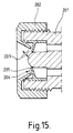
- Figure 15 shows an atomising nozzle in which, unlike those described so far, a means is provided for enabling the gap through which the liquid passes to be adjusted.
- the nozzle comprises a body 201 which has a threaded exterior to receive a threaded cap 202.
- the cap may be adjusted to alter a gap 203 formed between a face 204 of the cap and a flexible diaphragm 205. In this way the discharge characteristics may be readily adjusted; for example a spray may be adjusted from a fine to a coarse droplet size.
- liquid used in this specification includes solutions, suspensions and emulsions.
Abstract
Description
- The invention relates to atomising nozzles commonly used for, but not limited to, hand held sprayers such as so-called aerosols and pump type atomisers, intended for the application of liquid household, cosmetic and pharmaceutical products.
- Aerosol type sprayers are used throughout the world for dispensing a wide range of products, for example hair lacquer, furniture polish, cleaners, paint, insect killers and medicaments. Until recently, chlorofluorocarbons (CFC's) were the most common of the propellant gases used in aerosols because they are inert, miscible with a wide range of products, are easily liquefied under low pressures, give a substantially constant product flow-rate, and can produce sprays of droplets having mean diameters in the range of 3 to over 100 micrometers. However, in the 1970's it was confirmed that CFC's were probably responsible for depleting the Earth's protective ozone layer, and in 1987, most countries signed the Montreal Protocol to phase out the use of CFC's. Alternative propellants were then introduced - for example liquefied hydrocarbon gases such as butane, and carbon dioxide, which is dissolved in the product, - but these are flammable or otherwise harmful to the environment, or react with the product, and these propellant gases are gradually being phased out. There has been much development of aerosols powered by compressed gas (eg nitrogen, air), and manually operated pump atomisers, and for the majority of applications the performance of such sprayers is adequate.
- The main drawback of these non-CFC sprayers is that the smallest sized droplet that can be produced is about 40 micrometers diameter, and despite considerable development of so-called mechanical breakup nozzles, the use of high pressure (c 15 bars) pumps, and low viscosity/surface tension product formulations, 40 micrometers appears to be the lower limit achievable with prior art methods and devices.
- There are aerosol generators used for research and hospital applications, such as ultrasonic nebulisers and spinning disc generators, but neither is suitable for portable, convenient atomisers.
- It is also possible to force liquid at high pressure through a very small hole (5-10 micrometers diameter) to produce droplets of about 5 micrometers diameter, but these methods are unsuitable or uneconomic for large scale manufacture, mainly because of the difficulty in making very small holes in a suitable material, and, to prevent blockage of the hole, the need for exceptional cleanliness in the manufacture of the parts, together with ultrafiltration of the fluid to be sprayed.
- For veterinary and some human vaccination applications, high pressure (125 - 500 bars) spring or gas operated pumps (so-called needle-less injectors) are in common use to inject a jet of drug through the skin ("intra-dermal injection") without the use of needles, and attachments are available to convert the jet to a spray for administering drugs to the nasal passages of large animals such as swine. However, the smallest droplet size obtainable is in the order of 40 micrometers, and the range of applications for these injectors is limited.
- Compressed air atomisers such as air brushes and commercial paint sprayers consume large quantities of air, and to obtain droplets of 5 micrometers with water for example, a gas to liquid ratio of over 30,000:1 is required, which is impractical for convenient, portable sprayers.
- Nevertheless, there are some applications that rely on a smaller droplet size for maximum efficacy: space sprays such as flying insect killers should contain droplets ideally in the range of 20-30 micrometers diameter to ensure a long flotation time in the air, and for metered dose inhalers (MDI's) used for treating certain respiratory disorders it is essential that the aerodynamic particle size should be less than 15 micrometers, preferably less than 5 micrometers, so that the droplets are able to penetrate and deposit in the tracheobronchial and alveolar regions of the lung. For a spray composed of droplets with a range of sizes, more than 5% by weight of the droplets should have an aerodynamic size less than 6.4 micrometers, preferably more than 20 by weight of the particles have an aerodynamic size less than 6.4 micrometers.
- Inhalers may also be designed to deliver drugs to the alveolar sacs of the lung to provide a route for adsorption into the blood stream of drugs that are poorly adsorbed from the alimentary tract. To reach the alveoli it is essential that the aerodynamic size of the particles is less than 10 micrometers, preferably 0.5-5 micrometers.
- Many of the drugs used in the treatment of respiratory disorders are insoluble in vehicles such as water and are dispensed as suspensions. The drugs are produced in a respirable size of 1-5 micrometers. Particles of this size tend to block the very small holes (5-10 micrometers) used by known devices to generate droplets of about 5 micrometers diameter.
- The present invention aims to provide a design of atomising nozzle which is capable, inter alia, of being used to give a nozzle which will produce a spray of droplets of a size suitable for inhalation, without the use of liquefied gas propellants. However, the present invention is believed to be capable of being used to give a nozzle which will produce a spray of droplets having a mean diameter anywhere in the range of from 0.5 to over 100 micrometers.
- According to the present invention there is provided an atomising nozzle for producing a spray of droplets from a liquid passing through the nozzle under pressure, which nozzle comprises means defining an orifice; a closure member for the orifice, the orifice-defining means and closure member being relatively movable with respect to one another between a first position in which the closure member cooperates with the orifice to close it and a second position in which the closure member is spaced from the orifice-defining means to define a gap therebetween; and a stop for limiting relative movement between the orifice-defining means and the closure member to ensure that the width of the gap cannot exceed that which will produce a fine spray.
- Although the invention is intended mainly for metered dose inhalers and manually operated pumps, it may also be applied in other applications requiring small droplets, for example in certain industrial processes.
- In one embodiment of the present invention the nozzle has a circular orifice which is sealingly closed by a ball urged by a spring. Under the action of liquid under pressure, the ball is displaced from the orifice by an amount determined by the stop, which may be fixed or adjustable, and the fluid flows through the gap thus formed and emerges as a thin circular sheet. As the sheet of liquid expands it becomes thinner, and the outer edge breaks into droplets, the diameters of which are determined by the size of the gap, the pressure of liquid, and the physical properties of the liquid. When the pressure in the liquid is reduced below a predetermined level, the ball is urged by the spring sealingly onto the orifice, thus preventing ingress of dirt, evaporation of the product, and atmospheric contamination.
- In another embodiment of the invention, the liquid to be sprayed is caused to flow past a spherical surface and through a gap formed between that surface and a circumambient hole in a plate. The plate is preferably made of a spring material and located so that it is in sealing contact with the spherical surface as a normally closed valve. Under the action of liquid under pressure, the plate is forced away from the spherical surface by an amount determined by the stop, which may be fixed or adjustable, and the fluid flows through the gap thus formed to emerge as a thin circular sheet. As the sheet of liquid expands, it becomes thinner, and the outer edge breaks into droplets, the diameter of which are determined by the size of the gap, the pressure of liquid and the physical properties of the liquid. When the pressure in the liquid is reduced below a predetermined level, the spring plate returns to its original position to seal against the spherical surface, thus preventing ingress of dirt, evaporation of the remaining product, and atmospheric contamination.
- Whilst reference has been made above to the use of a ball or spherical surface in co-operation with a circular orifice in a plate or nozzle, other shapes could be used, for example, a conical surface co-operating with a circular hole. The precise profile of the surface and hole will be determined in part by the spray pattern required, and the present invention provides for all combinations of surfaces and holes, but it is preferred that at least one of the components has a varying cross section so that the gap between them is opened or closed as a result of relative movement. Since the stop ensures that the gap is of substantially constant size when the components are fully apart, an even spray results from the passage of fluid throughout the length of the gap. The width of the gap is preferably of the order of 5 micrometers. The ratio of the length of the gap L to the width of the gap D is preferably not more than 1 and more preferably not more than 0.5. By the "length" of the gap we mean the distance which the liquid has to travel in order to pass through the gap.
- The surface finish of the co-operating components in the region of the gap should be sufficiently fine so as not to adversely affect the droplet size and pattern of the spray: for example, a groove in one component would cause a stream of liquid to issue therefrom, which would probably not have the required characteristics, and could lower the pressure in the liquid sufficiently to adversely affect the quality of spray emerging from the remainder of the gap. The finish should be sufficiently fine to ensure efficient sealing between the components when in the closed position.
- The invention further provides an atomising device which comprises an atomising nozzle according to the present invention, a supply of liquid, and means for providing liquid under pressure from said supply to said nozzle.
- In one form, the device is an inhalation device, and the liquid comprises a medicament suitable for inhalation. The liquid may contain the medicament in suspension or solution, and the liquid may be an aqueous or non-aqueous liquid which is physiologically acceptable.
- In the accompanying drawings:
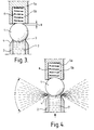
- Figure 1 illustrates the principle of the invention and is a cross sectional view of the basic elements in their normal, non-pressurised relationship.
- Figure 2 is a similar view to Figure 1, and shows the elements in the operating position.
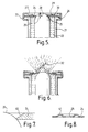
- Figures 3 and 4 show a modified form of the embodiment of Figures 1 and 2.
- Figures 5 and 6 show an alternative embodiment of the principle of the invention, in closed and open position respectively.
- Figure 7 is an enlarged part section showing the conjunction of the principal components illustrated in Figures 5 and 6.
- Figure 8 shows a section through a modified version of the spring plate used in the embodiment Figures 5 and 6.
- Figures 9 and 10 show a modified form of the embodiment of Figures 5 and 6.
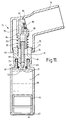
- Figures 11 and 12 show a spray device for use as an inhaler, incorporating a nozzle according to the present invention.
- Figure 13 shows the nozzle used in Figures 11 and 12, on a larger scale.
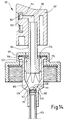
- Figure 14 shows another form of spray device incorporating the nozzle according to the invention.
- Figure 15 shows an embodiment of the nozzle having a gap of adjustable size.
- Referring to Figure 1, ball 1 is resiliently urged by a
compression spring 6 into a position in which it is sealingly located on thecircular orifice 3 ofnozzle 2.Stop means 5 is located on the longitudinal axis of the ball and orifice, and has agap 8 between theface 9 of the stop means 5 and the surface of ball 1.Nozzle 2 is in hydraulic communication with a dispensing means (not shown) and containsliquid 7 which is to be sprayed. - Referring now to Figure 2, which illustrates the same components as in Figure 1, pressure has been applied to the
liquid 7 by the dispensing means, and ball 1 is lifted from thecircular orifice 3 against the force ofspring 6 until it stops against theface 9 of stop means 5. Thus the ball 1 has moved by an amount controlled by thegap 8 to form agap 10, the size of which is less thangap 8 by an amount determined by the ratio of the diameters of the ball 1 andcircular orifice 3. Theliquid 7 issues through thegap 10 as a circular sheet of thickness initially determined by the size ofgap 10. As the liquid sheet expands it becomes thinner, until the surface tension of the liquid is unable to maintain homogeneity of the sheet, and the periphery of the sheet breaks into small droplets. The size of the droplets is controlled by the dimension of thegap 10 and the velocity of the liquid, which in turn depends on the pressure generated in the dispenser. Asmaller gap 10 will generally produce smaller droplets, provided that the pressure in the liquid is sufficiently high to overcome the viscous drag created by the small gap, and accelerate the liquid to form a thin sheet. (If the pressure is too low, the liquid will merely ooze from the gap). - When the pressure in the
liquid 7 ceases, the ball 1 is returned to sealing contact withorifice 3 byspring 6. It is preferable that the contact line between the ball 1 andorifice 3 is very thin, which may be facilitated by chamfering the nozzle as at 4, so as to leave a knife edge. This may have the additional effect of allowing a wider spray angle Z than possible with a square-edged orifice. - Figures 3 and 4 show a modification in which the stop means 5 is replaced by an alternative stop means 5a which has a
recess 5b within which thespring 6 is housed. When the nozzle goes from the closed position shown in Figure 3 to the open position shown in Figure 4, the ball 1 seats itself in the open end of the recess. The guidance which this provides ensures that the ball is correctly aligned with respect to the end of theconduit 2, with a uniform annular gap between theorifice 3 and the ball. The spray produced is thus substantially uniform both in distribution around the gap and in droplet size. - An alternative embodiment is shown in Figures 5 and 6. In this case, Figure 5 shows a
spherical surface 20 which is located at the outer edge of thedischarge conduit 21 containing the liquid to be sprayed 22. Aspring plate 24 having acircular orifice 25 is held against thespherical surface 20 so that thecircular orifice 25 makes sealing contact with thespherical surface 25, and the outer edge of thespring plate 24 is in sealing contact with theabutment face 26 ofconduit 21, thus preventing the passage ofliquid 22. Aplate 27 having acircular hole 29 is assembled on to the outer face ofspring plate 24 so that thehole 29 is co-axial withorifice 25. A step orrecess 30 inplate 27 provides agap 28 between thespring plate 24 andplate 27, the assembly of the two plates being held in sealing contact with theabutment 26 by retainingmember 33, which may be a crimped-on ring as shown. - Referring to Figure 6, the liquid 22 is pressurised by the dispensing means (not shown), and forces plate 24 away from the
spherical surface 20, against the inherent bias provided by the fact that theplate 24 is a spring plate, to create thegap 32 between thecircular orifice 25 andspherical surface 20. The size of thegap 32 is determined by the size of thegap 28 and by the diameter of thehole 29 in theplate 27, which, between them, determine the extent to which thespring plate 24 can flex. The liquid issues from thegap 32 as a thin circular sheet, the outer edge of which breaks into droplets as previously described. The edge of thecircular orifice 25 inspring plate 24 may have achamfer 40 as shown in Figure 7, which may permit a wider spray angle than possible with a square-edged orifice. Thespring plate 24 may have corrugations co-axial with theorifice 25 as shown in Figure 8, which will facilitate the flexing of the spring plate. When the pressure is removed from the liquid 22, thespring plate 24 returns to sealing contact with thespherical surface 20. - In Figures 5 and 6 the
spherical surface 20 is shown diagrammatically as being at the end of a rod, and means (not shown) would be required to support the rod with respect to thefluid discharge conduit 21. Figures 9 and 10 show a modified embodiment in which there is aspherical surface 20a formed on adisc 50 which is secured to, or integral with, the inner wall of theconduit 21. Thedisc 50 is provided with at least oneport 51 through which liquid can pass from the interior of theconduit 21 to the region immediately below theplate 24. - Figures 11 to 13 show a spray device incorporating an atomising nozzle according to the present invention. It is intended for use as an inhalation device. It comprises a
reservoir 60 ofliquid 61. The liquid 61 may, for example, consist of an aqueous suspension of a medicament suitable for treatment of a condition such as asthma. The lower end of the reservoir is defined by apiston 62 which is longitudinally slidable within the reservoir. Beneath the piston is astopper 63 which has at least oneorifice 64 therein to permit air to enter the space beneath the piston. - The upper end of the reservoir has a
neck portion 65 to which aclosure member 66 is secured. Aportion 67 of the closure member extends within the neck, and an O-ring seal 68 provides a seal between theneck portion 65 and theportion 67. Theclosure member 66 has apassage 69 therethrough and atube 70 is secured in the upper portion of this passage. The lower portion of the passage defines anorifice 71, above which is a tapered portion defining a seat for acheck valve ball 72. The ball is urged against the seat by acompression spring 73. - An
outlet member 74 is mounted on theclosure member 66 so as to be movable with respect thereto. Theoutlet member 74 comprises a generallycylindrical part 75 the lower end of which engages over theclosure member 66. Thepart 75 is prevented from separating from theclosure member 66 byinterengaging flanges outlet member 74 further comprises anoutlet spout 78 through which a user can inhale through his or her mouth. In the case of an inhaler for nasal use, thespout 78 would be replaced by an appropriate nasal outlet. - In the region of the junction between the
cylindrical part 75 and theoutlet 78, theoutlet member 74 has an inwardly extendingwall 79 which serves to retain an atomisingarrangement 80. This includes ablock 81 which has a hollowlower portion 82 which surrounds the upper end of thetube 70 and which is free to enter acavity 83 in the upper end of theclosure member 66. Thehollow portion 82 has an outwardly extendingflange 84 at its upper end, and acompression spring 85 is mounted between the flange and theclosure member 66. - The interior of the
hollow portion 82 communicates via apassage 86 with an atomisingnozzle 90 according to the invention. This is shown on a larger scale in Figure 13. As can be seen there, it corresponds substantially to what is shown in Figures 9 and 10, and comprises aspring plate 91 which cooperates with aspherical surface 92 formed on adisc 93. Thedisc 93 is provided with at least oneport 94 therethrough. - In operation, the user places his or her mouth over the
spout 78 and squeezes thereservoir 60 andoutlet member 74 together against the force of thecompression spring 85 to bring the device into the position shown in Figure 12. During this operation, theball 72 prevents liquid leaving thereservoir 60 through theorifice 71, and thetube 70 acts as a piston to expel part of the liquid above the ball through thenozzle 90 where it forms an atomised spray. The quantity of liquid expelled in this way constitutes a metered dose, metering being effected by the stroke of the piston. The user inhales this spray. When the user ceases to hold thereservoir 60 andoutlet member 74 together, thespring 85 forces them apart. This creates a suction effect within thetube 70 which draws theball 72 away from its seat and permits liquid to pass from the reservoir through theorifice 71 to replenish what has just been dispensed through thenozzle 90. As the volume of liquid within the reservoir is reduced, thepiston 62 slides upwardly under the force of the atmospheric pressure below it, air reaching the underside of the piston through theport 64. - Figure 14, shows another embodiment of spray device. The figure shows the device in the discharge position. In this embodiment, a valve of similar design to that used as the atomising nozzle is used also as a non-return inlet valve. Figure 14 shows an
actuator 101 sealingly located on ahollow stem 104 which is integral with ahollow piston 107.Piston 107 is slidingly located within thecylinder 115, the cylinder being formed as the inner part of apump body 108. The body is retained by a snap fit or other convenient method of retention in aclosure 105, agasket 106 providing a seal between thestem 104 and theclosure 105.Gasket 106 is free to flex with axial displacement of the piston and stem, whilst maintaining a seal. A plurality of cantilever springs 109, formed integrally withpiston 107, urges the piston in an outward direction by reacting against aconical surface 110 formed in the lower part of thepump body 108. The piston is prevented from coming out of thepump body 108 by anabutment 116 closing on to thegasket 106 which is supported by the inside of theclosure 105. - The lower end of the
pump body 108 contains aspherical surface 111. Aflexible diaphragm 112 with a circular hole therein is sealingly located in thepump body 108 so that the edge of the hole is in sealing engagement with thespherical surface 111. The combination ofdiaphragm 112 andsurface 111 acts as a normally closednon-return valve 120. The extreme lower part of thepump body 108 terminates in a diameter adapted to sealingly retain adip tube 113. The conduit defined by thedip tube 113 and extreme lower part of thepump body 108 is in communication with anannulus 119 formed between thespherical surface 111 and thediaphragm 112 via one ormore ports 117. Theactuator 101 has aspherical surface 103, and aflexible diaphragm 102 with a circular hole therein, the edge of which hole is in sealing engagement with thespherical surface 103. Thediaphragm 102 is sealingly located by a snap fit or other convenient method within theactuator 101, and the combination ofdiaphragm 102 andsurface 103 acts as a combined non-return valve and atomisingnozzle 121. Thehollow stem 104 is in communication withannulus 114 via aport 118. - In operation, the actuator is depressed and allowed to return several times to prime the pump, the
valves - Figure 15 shows an atomising nozzle in which, unlike those described so far, a means is provided for enabling the gap through which the liquid passes to be adjusted. The nozzle comprises a
body 201 which has a threaded exterior to receive a threadedcap 202. The cap may be adjusted to alter agap 203 formed between aface 204 of the cap and aflexible diaphragm 205. In this way the discharge characteristics may be readily adjusted; for example a spray may be adjusted from a fine to a coarse droplet size. - The description "liquid" used in this specification includes solutions, suspensions and emulsions.
Claims (22)
- An atomising nozzle for producing a spray of droplets from a liquid passing through the nozzle under pressure, which nozzle comprises means defining an orifice; a closure member for the orifice, the orifice-defining means and closure member being relatively movable with respect to one another between a first position in which the closure member cooperates with the orifice to close it and a second position in which the closure member is spaced from the orifice-defining means to define a gap therebetween, and a stop for limiting relative movement between the orifice-defining means and the closure member to ensure that the width of the said gap cannot exceed that which would produce a fine spray.
- A nozzle according to claim 1, wherein the orifice is circular.
- A nozzle according to claim 2, wherein the closure member has an at least partly spherical surface positioned to cooperate with the orifice.
- A nozzle according to any preceding claim, wherein the orifice-defining means is a flexible diaphragm.
- A nozzle according to claim 4, wherein the diaphragm is provided with at least one corrugation surrounding the orifice, whereby to increase the flexibility of the diaphragm.
- A nozzle according to claim 4 or 5, wherein the stop comprises an annular ring having a stop surface located adjacent to, but spaced from, the diaphragm.
- A nozzle according to any preceding claim, wherein the closure member is a spherical ball.
- A nozzle according to any preceding claim, wherein the orifice-defining means and the closure member are relatively movable with respect to one another under a force exerted by pressure of the liquid.
- A nozzle according to any preceding claim, wherein the orifice has a chamfered peripheral surface, the direction of chamfering being such as to reduce the length of the said gap.
- A nozzle according to any preceding claim, wherein the width of the said gap is of the order of 5 micrometers.
- A nozzle according to any preceding claim, wherein the value of L/D, where L is the length of the said gap and D is the width of the said gap, is not more than 1.
- A nozzle according to claim 11, wherein the value of L/D is not more than 0.5.
- A nozzle according to any preceding claim, wherein the orifice-defining means and the closure member are biassed to the said first position.
- A nozzle according to claim 13, wherein the said bias is a resilient bias.
- A nozzle according to claim 14, wherein the said resilient bias is provided by the orifice-defining member being resiliently movable.
- An atomising device, which comprises an atomising nozzle according to any preceding claim, a supply of the said liquid, and means for providing liquid under pressure from said supply to said nozzle.
- A device according to claim 16, comprising metering means for ensuring that the said liquid passes through the said nozzle in metered quantities.
- A device according to claim 16 or 17, wherein the said liquid comprises a medicament suitable for inhalation.
- A device according to claim 18, wherein the said liquid contains the said medicament in suspension.
- A device according to claim 18, wherein the said liquid contains the said medicament in solution.
- A device according to claim 18, 19 or 20, wherein the said liquid is a physiologically acceptable aqueous liquid.
- A device according to claim 18, 19 or 20, wherein the said liquid is a physiologically acceptable non-aqueous liquid.
Applications Claiming Priority (4)
| Application Number | Priority Date | Filing Date | Title |
|---|---|---|---|
| GB919114080A GB9114080D0 (en) | 1991-06-28 | 1991-06-28 | Atomising valve |
| GB9114080 | 1991-06-28 | ||
| GB929205969A GB9205969D0 (en) | 1991-06-28 | 1992-03-18 | Atomising pump |
| GB9205969 | 1992-03-18 |
Publications (2)
| Publication Number | Publication Date |
|---|---|
| EP0520571A1 true EP0520571A1 (en) | 1992-12-30 |
| EP0520571B1 EP0520571B1 (en) | 1998-09-09 |
Family
ID=26299156
Family Applications (1)
| Application Number | Title | Priority Date | Filing Date |
|---|---|---|---|
| EP92201841A Expired - Lifetime EP0520571B1 (en) | 1991-06-28 | 1992-06-23 | Atomising nozzle |
Country Status (14)
| Country | Link |
|---|---|
| EP (1) | EP0520571B1 (en) |
| JP (1) | JP3162487B2 (en) |
| AR (1) | AR247836A1 (en) |
| AT (1) | ATE170778T1 (en) |
| AU (1) | AU1859192A (en) |
| BR (1) | BR9202411A (en) |
| CA (1) | CA2072544A1 (en) |
| DE (1) | DE69226908T2 (en) |
| DK (1) | DK0520571T3 (en) |
| ES (1) | ES2119794T3 (en) |
| FI (1) | FI922965A (en) |
| IE (1) | IE80891B1 (en) |
| MX (1) | MX9203622A (en) |
| NZ (1) | NZ243321A (en) |
Cited By (26)
| Publication number | Priority date | Publication date | Assignee | Title |
|---|---|---|---|---|
| WO1996016746A1 (en) * | 1994-12-01 | 1996-06-06 | Josef Wischerath Gmbh & Co., Kg | Dispenser |
| US5881954A (en) * | 1993-04-30 | 1999-03-16 | Danmist Aps | Method and device for atomising fluids |
| US5964416A (en) * | 1995-10-04 | 1999-10-12 | Boehringer Ingelheim Gmbh | Device for producing high pressure in a fluid in miniature |
| DE19919461A1 (en) * | 1999-04-29 | 2000-11-02 | Elias Russegger | Closable nozzle for fluid media has outlet opening and closing element movable relative to each other against spring force where spring is formed by membrane which can be part of housing wall |
| EP1188486A2 (en) * | 2000-08-10 | 2002-03-20 | Carow International, Inc. | Pump actuator with plastic spring |
| WO2005107837A1 (en) * | 2004-05-03 | 2005-11-17 | Boehringer Ingelheim International Gmbh | Atomizer for distributing liquids for medical purposes |
| USRE43174E1 (en) | 2000-04-11 | 2012-02-14 | Trudell Medical International | Aerosol delivery apparatus |
| AT515995A1 (en) * | 2014-07-10 | 2016-01-15 | Tech Universität Graz | Apparatus and method for atomizing a liquid |
| US9545487B2 (en) | 2012-04-13 | 2017-01-17 | Boehringer Ingelheim International Gmbh | Dispenser with encoding means |
| US9682202B2 (en) | 2009-05-18 | 2017-06-20 | Boehringer Ingelheim International Gmbh | Adapter, inhalation device, and atomizer |
| US9700689B2 (en) | 2002-05-21 | 2017-07-11 | Trudell Medical International | Medication delivery apparatus and system and methods for the use and assembly thereof |
| US9724482B2 (en) | 2009-11-25 | 2017-08-08 | Boehringer Ingelheim International Gmbh | Nebulizer |
| US9744313B2 (en) | 2013-08-09 | 2017-08-29 | Boehringer Ingelheim International Gmbh | Nebulizer |
| US9757750B2 (en) | 2011-04-01 | 2017-09-12 | Boehringer Ingelheim International Gmbh | Medicinal device with container |
| US9827384B2 (en) | 2011-05-23 | 2017-11-28 | Boehringer Ingelheim International Gmbh | Nebulizer |
| US9943654B2 (en) | 2010-06-24 | 2018-04-17 | Boehringer Ingelheim International Gmbh | Nebulizer |
| US10004857B2 (en) | 2013-08-09 | 2018-06-26 | Boehringer Ingelheim International Gmbh | Nebulizer |
| US10011906B2 (en) | 2009-03-31 | 2018-07-03 | Beohringer Ingelheim International Gmbh | Method for coating a surface of a component |
| US10016568B2 (en) | 2009-11-25 | 2018-07-10 | Boehringer Ingelheim International Gmbh | Nebulizer |
| US10099022B2 (en) | 2014-05-07 | 2018-10-16 | Boehringer Ingelheim International Gmbh | Nebulizer |
| US10124125B2 (en) | 2009-11-25 | 2018-11-13 | Boehringer Ingelheim International Gmbh | Nebulizer |
| US10124129B2 (en) | 2008-01-02 | 2018-11-13 | Boehringer Ingelheim International Gmbh | Dispensing device, storage device and method for dispensing a formulation |
| US10195374B2 (en) | 2014-05-07 | 2019-02-05 | Boehringer Ingelheim International Gmbh | Container, nebulizer and use |
| WO2019086823A1 (en) * | 2017-10-31 | 2019-05-09 | Leafgreen Limited | Spray configuration |
| US10722666B2 (en) | 2014-05-07 | 2020-07-28 | Boehringer Ingelheim International Gmbh | Nebulizer with axially movable and lockable container and indicator |
| CN115089824A (en) * | 2022-06-15 | 2022-09-23 | 宁波司麦儿医学科技有限公司 | Atomizer |
Families Citing this family (3)
| Publication number | Priority date | Publication date | Assignee | Title |
|---|---|---|---|---|
| US6293279B1 (en) * | 1997-09-26 | 2001-09-25 | Trudell Medical International | Aerosol medication delivery apparatus and system |
| CN105104119A (en) * | 2015-08-19 | 2015-12-02 | 张萍 | Intelligent irrigation apparatus capable of implementing wireless communication for landscape gardening engineering |
| DE102016123993B4 (en) * | 2016-12-09 | 2021-12-30 | Aebi Schmidt Nederland Bv | Liquid jet shut-off nozzle |
Citations (2)
| Publication number | Priority date | Publication date | Assignee | Title |
|---|---|---|---|---|
| US3794247A (en) * | 1972-11-22 | 1974-02-26 | Corsette Douglas Frank | Spray fitment for squeeze bottles |
| US4437611A (en) * | 1979-10-10 | 1984-03-20 | Macmillan Bloedel Limited | Self protecting spray nozzle |
-
1992
- 1992-06-23 DK DK92201841T patent/DK0520571T3/en active
- 1992-06-23 DE DE69226908T patent/DE69226908T2/en not_active Expired - Fee Related
- 1992-06-23 AT AT92201841T patent/ATE170778T1/en not_active IP Right Cessation
- 1992-06-23 EP EP92201841A patent/EP0520571B1/en not_active Expired - Lifetime
- 1992-06-23 ES ES92201841T patent/ES2119794T3/en not_active Expired - Lifetime
- 1992-06-26 JP JP16958392A patent/JP3162487B2/en not_active Expired - Fee Related
- 1992-06-26 CA CA002072544A patent/CA2072544A1/en not_active Abandoned
- 1992-06-26 AU AU18591/92A patent/AU1859192A/en not_active Abandoned
- 1992-06-26 FI FI922965A patent/FI922965A/en not_active Application Discontinuation
- 1992-06-26 AR AR92322635A patent/AR247836A1/en active
- 1992-06-26 MX MX9203622A patent/MX9203622A/en unknown
- 1992-06-26 BR BR929202411A patent/BR9202411A/en not_active IP Right Cessation
- 1992-06-26 NZ NZ243321A patent/NZ243321A/en unknown
- 1992-07-01 IE IE922089A patent/IE80891B1/en not_active IP Right Cessation
Patent Citations (2)
| Publication number | Priority date | Publication date | Assignee | Title |
|---|---|---|---|---|
| US3794247A (en) * | 1972-11-22 | 1974-02-26 | Corsette Douglas Frank | Spray fitment for squeeze bottles |
| US4437611A (en) * | 1979-10-10 | 1984-03-20 | Macmillan Bloedel Limited | Self protecting spray nozzle |
Cited By (43)
| Publication number | Priority date | Publication date | Assignee | Title |
|---|---|---|---|---|
| US5881954A (en) * | 1993-04-30 | 1999-03-16 | Danmist Aps | Method and device for atomising fluids |
| WO1996016746A1 (en) * | 1994-12-01 | 1996-06-06 | Josef Wischerath Gmbh & Co., Kg | Dispenser |
| US5964416A (en) * | 1995-10-04 | 1999-10-12 | Boehringer Ingelheim Gmbh | Device for producing high pressure in a fluid in miniature |
| US6402055B1 (en) | 1995-10-04 | 2002-06-11 | Boehringer Ingelheim Gmbh | Device for producing high pressure in a fluid in miniature |
| US6497373B2 (en) | 1995-10-04 | 2002-12-24 | Boehringer International Gmbh | Device for producing high pressure in a fluid in miniature |
| US6918547B2 (en) | 1995-10-04 | 2005-07-19 | Joachim Jaeger | Device for producing high pressure in a fluid in miniature |
| US7104470B2 (en) | 1995-10-04 | 2006-09-12 | Boehringer Ingelheim International Gmbh | Device for producing high pressure in a fluid in miniature |
| DE19919461A1 (en) * | 1999-04-29 | 2000-11-02 | Elias Russegger | Closable nozzle for fluid media has outlet opening and closing element movable relative to each other against spring force where spring is formed by membrane which can be part of housing wall |
| USRE43174E1 (en) | 2000-04-11 | 2012-02-14 | Trudell Medical International | Aerosol delivery apparatus |
| USRE46050E1 (en) | 2000-04-11 | 2016-07-05 | Trudell Medical International | Aerosol delivery apparatus |
| USRE45068E1 (en) | 2000-04-11 | 2014-08-12 | Trudell Medical International | Aerosol delivery apparatus |
| EP1188486A3 (en) * | 2000-08-10 | 2002-05-15 | Carow International, Inc. | Pump actuator with plastic spring |
| EP1188486A2 (en) * | 2000-08-10 | 2002-03-20 | Carow International, Inc. | Pump actuator with plastic spring |
| US10881816B2 (en) | 2002-05-21 | 2021-01-05 | Trudell Medical International | Medication delivery apparatus and system and methods for the use and assembly thereof |
| US9814849B2 (en) | 2002-05-21 | 2017-11-14 | Trudell Medical International | Medication delivery apparatus and system and methods for the use and assembly thereof |
| US9700689B2 (en) | 2002-05-21 | 2017-07-11 | Trudell Medical International | Medication delivery apparatus and system and methods for the use and assembly thereof |
| US7819342B2 (en) | 2004-05-03 | 2010-10-26 | Boehringer Ingelheim International Gmbh | Atomizer for dispensing liquids for medical purposes |
| EA009854B1 (en) * | 2004-05-03 | 2008-04-28 | Бёрингер Ингельхайм Интернациональ Гмбх | Atomizer for distributing liquids for medical purposes |
| WO2005107837A1 (en) * | 2004-05-03 | 2005-11-17 | Boehringer Ingelheim International Gmbh | Atomizer for distributing liquids for medical purposes |
| US10124129B2 (en) | 2008-01-02 | 2018-11-13 | Boehringer Ingelheim International Gmbh | Dispensing device, storage device and method for dispensing a formulation |
| US10011906B2 (en) | 2009-03-31 | 2018-07-03 | Beohringer Ingelheim International Gmbh | Method for coating a surface of a component |
| US9682202B2 (en) | 2009-05-18 | 2017-06-20 | Boehringer Ingelheim International Gmbh | Adapter, inhalation device, and atomizer |
| US9724482B2 (en) | 2009-11-25 | 2017-08-08 | Boehringer Ingelheim International Gmbh | Nebulizer |
| US10016568B2 (en) | 2009-11-25 | 2018-07-10 | Boehringer Ingelheim International Gmbh | Nebulizer |
| US10124125B2 (en) | 2009-11-25 | 2018-11-13 | Boehringer Ingelheim International Gmbh | Nebulizer |
| US9943654B2 (en) | 2010-06-24 | 2018-04-17 | Boehringer Ingelheim International Gmbh | Nebulizer |
| US9757750B2 (en) | 2011-04-01 | 2017-09-12 | Boehringer Ingelheim International Gmbh | Medicinal device with container |
| US9827384B2 (en) | 2011-05-23 | 2017-11-28 | Boehringer Ingelheim International Gmbh | Nebulizer |
| US9545487B2 (en) | 2012-04-13 | 2017-01-17 | Boehringer Ingelheim International Gmbh | Dispenser with encoding means |
| US10220163B2 (en) | 2012-04-13 | 2019-03-05 | Boehringer Ingelheim International Gmbh | Nebuliser with coding means |
| US10004857B2 (en) | 2013-08-09 | 2018-06-26 | Boehringer Ingelheim International Gmbh | Nebulizer |
| US9744313B2 (en) | 2013-08-09 | 2017-08-29 | Boehringer Ingelheim International Gmbh | Nebulizer |
| US11642476B2 (en) | 2013-08-09 | 2023-05-09 | Boehringer Ingelheim International Gmbh | Nebulizer |
| US10894134B2 (en) | 2013-08-09 | 2021-01-19 | Boehringer Ingelheim International Gmbh | Nebulizer |
| US10716905B2 (en) | 2014-02-23 | 2020-07-21 | Boehringer Lngelheim International Gmbh | Container, nebulizer and use |
| US10195374B2 (en) | 2014-05-07 | 2019-02-05 | Boehringer Ingelheim International Gmbh | Container, nebulizer and use |
| US10722666B2 (en) | 2014-05-07 | 2020-07-28 | Boehringer Ingelheim International Gmbh | Nebulizer with axially movable and lockable container and indicator |
| US10099022B2 (en) | 2014-05-07 | 2018-10-16 | Boehringer Ingelheim International Gmbh | Nebulizer |
| AT515995A1 (en) * | 2014-07-10 | 2016-01-15 | Tech Universität Graz | Apparatus and method for atomizing a liquid |
| AT515995B1 (en) * | 2014-07-10 | 2018-08-15 | Univ Graz Tech | Apparatus and method for atomizing a liquid |
| WO2019086823A1 (en) * | 2017-10-31 | 2019-05-09 | Leafgreen Limited | Spray configuration |
| CN115089824A (en) * | 2022-06-15 | 2022-09-23 | 宁波司麦儿医学科技有限公司 | Atomizer |
| CN115089824B (en) * | 2022-06-15 | 2024-02-02 | 宁波司麦儿医学科技有限公司 | Atomizer |
Also Published As
| Publication number | Publication date |
|---|---|
| NZ243321A (en) | 1994-11-25 |
| MX9203622A (en) | 1993-11-01 |
| EP0520571B1 (en) | 1998-09-09 |
| JP3162487B2 (en) | 2001-04-25 |
| DE69226908T2 (en) | 1999-01-28 |
| JPH06178954A (en) | 1994-06-28 |
| CA2072544A1 (en) | 1992-12-29 |
| ES2119794T3 (en) | 1998-10-16 |
| BR9202411A (en) | 1993-01-26 |
| ATE170778T1 (en) | 1998-09-15 |
| DE69226908D1 (en) | 1998-10-15 |
| IE922089A1 (en) | 1992-12-30 |
| AR247836A1 (en) | 1995-04-28 |
| DK0520571T3 (en) | 1999-06-07 |
| AU1859192A (en) | 1993-01-07 |
| FI922965A (en) | 1992-12-29 |
| IE80891B1 (en) | 1999-05-19 |
| FI922965A0 (en) | 1992-06-26 |
Similar Documents
| Publication | Publication Date | Title |
|---|---|---|
| US5370318A (en) | Atomizing nozzle for producing a spray from a liquid under pressure | |
| EP0520571B1 (en) | Atomising nozzle | |
| US6056213A (en) | Modular system for atomizing a liquid | |
| US5152435A (en) | Ophthalmic dispensing pump | |
| US7681811B2 (en) | System comprising a nozzle and a fixing means therefor | |
| RU2104048C1 (en) | Apparatus for dosed dispensing of metered quantities of liquid in the form of drop flare under pressure | |
| US5341993A (en) | Topical sprayer with remotely actuated spray tip | |
| US20050263618A1 (en) | Atomizer for dispensing liquids for medical purposes | |
| WO2003051523A1 (en) | Dispensing means for dispensing atomized liquid | |
| PL185789B1 (en) | Fluid sprayer, containing miniaturized fluid compression device | |
| US20100116909A1 (en) | Nozzle and dispenser incorporating a nozzle | |
| CN108348931A (en) | Spray nozzle device | |
| US5350116A (en) | Dispensing apparatus | |
| DK142132B (en) | Aerosol nebulizer with manually operated atomisers. | |
| US5816504A (en) | Discharge apparatus for flowable media | |
| US20050023295A1 (en) | Dosing device with an application top | |
| JP4343314B2 (en) | Spray products | |
| US20240001382A1 (en) | Spray dispenser | |
| EP1917106A1 (en) | A nozzle and a dispenser having such a nozzle | |
| WO2017204828A1 (en) | Non-clog nozzle, actuator and valve assembly for bag-on-valve or can-on-valve systems |
Legal Events
| Date | Code | Title | Description |
|---|---|---|---|
| PUAI | Public reference made under article 153(3) epc to a published international application that has entered the european phase |
Free format text: ORIGINAL CODE: 0009012 |
|
| AK | Designated contracting states |
Kind code of ref document: A1 Designated state(s): AT BE CH DE DK ES FR GB GR IT LI LU MC NL PT SE |
|
| 17P | Request for examination filed |
Effective date: 19930510 |
|
| 17Q | First examination report despatched |
Effective date: 19940803 |
|
| RAP1 | Party data changed (applicant data changed or rights of an application transferred) |
Owner name: WESTON, TERENCE EDWARD |
|
| GRAG | Despatch of communication of intention to grant |
Free format text: ORIGINAL CODE: EPIDOS AGRA |
|
| RAP1 | Party data changed (applicant data changed or rights of an application transferred) |
Owner name: WESTON MEDICAL LIMITED |
|
| GRAG | Despatch of communication of intention to grant |
Free format text: ORIGINAL CODE: EPIDOS AGRA |
|
| GRAH | Despatch of communication of intention to grant a patent |
Free format text: ORIGINAL CODE: EPIDOS IGRA |
|
| GRAH | Despatch of communication of intention to grant a patent |
Free format text: ORIGINAL CODE: EPIDOS IGRA |
|
| GRAA | (expected) grant |
Free format text: ORIGINAL CODE: 0009210 |
|
| AK | Designated contracting states |
Kind code of ref document: B1 Designated state(s): AT BE CH DE DK ES FR GB GR IT LI LU MC NL PT SE |
|
| REF | Corresponds to: |
Ref document number: 170778 Country of ref document: AT Date of ref document: 19980915 Kind code of ref document: T |
|
| REG | Reference to a national code |
Ref country code: CH Ref legal event code: NV Representative=s name: TROESCH SCHEIDEGGER WERNER AG Ref country code: CH Ref legal event code: EP |
|
| REF | Corresponds to: |
Ref document number: 69226908 Country of ref document: DE Date of ref document: 19981015 |
|
| REG | Reference to a national code |
Ref country code: ES Ref legal event code: FG2A Ref document number: 2119794 Country of ref document: ES Kind code of ref document: T3 |
|
| ET | Fr: translation filed | ||
| REG | Reference to a national code |
Ref country code: PT Ref legal event code: SC4A Free format text: AVAILABILITY OF NATIONAL TRANSLATION Effective date: 19981113 |
|
| REG | Reference to a national code |
Ref country code: DK Ref legal event code: T3 |
|
| PG25 | Lapsed in a contracting state [announced via postgrant information from national office to epo] |
Ref country code: LU Free format text: LAPSE BECAUSE OF NON-PAYMENT OF DUE FEES Effective date: 19990623 |
|
| PLBE | No opposition filed within time limit |
Free format text: ORIGINAL CODE: 0009261 |
|
| STAA | Information on the status of an ep patent application or granted ep patent |
Free format text: STATUS: NO OPPOSITION FILED WITHIN TIME LIMIT |
|
| 26N | No opposition filed | ||
| PG25 | Lapsed in a contracting state [announced via postgrant information from national office to epo] |
Ref country code: MC Free format text: LAPSE BECAUSE OF NON-PAYMENT OF DUE FEES Effective date: 19991231 |
|
| REG | Reference to a national code |
Ref country code: GB Ref legal event code: IF02 |
|
| PGFP | Annual fee paid to national office [announced via postgrant information from national office to epo] |
Ref country code: FR Payment date: 20020610 Year of fee payment: 11 |
|
| PGFP | Annual fee paid to national office [announced via postgrant information from national office to epo] |
Ref country code: SE Payment date: 20020611 Year of fee payment: 11 Ref country code: PT Payment date: 20020611 Year of fee payment: 11 |
|
| PGFP | Annual fee paid to national office [announced via postgrant information from national office to epo] |
Ref country code: AT Payment date: 20020612 Year of fee payment: 11 |
|
| PGFP | Annual fee paid to national office [announced via postgrant information from national office to epo] |
Ref country code: DK Payment date: 20020614 Year of fee payment: 11 |
|
| PGFP | Annual fee paid to national office [announced via postgrant information from national office to epo] |
Ref country code: ES Payment date: 20020618 Year of fee payment: 11 |
|
| PGFP | Annual fee paid to national office [announced via postgrant information from national office to epo] |
Ref country code: GB Payment date: 20020619 Year of fee payment: 11 |
|
| PGFP | Annual fee paid to national office [announced via postgrant information from national office to epo] |
Ref country code: GR Payment date: 20020626 Year of fee payment: 11 Ref country code: DE Payment date: 20020626 Year of fee payment: 11 |
|
| PGFP | Annual fee paid to national office [announced via postgrant information from national office to epo] |
Ref country code: NL Payment date: 20020628 Year of fee payment: 11 |
|
| PGFP | Annual fee paid to national office [announced via postgrant information from national office to epo] |
Ref country code: CH Payment date: 20020702 Year of fee payment: 11 |
|
| PGFP | Annual fee paid to national office [announced via postgrant information from national office to epo] |
Ref country code: BE Payment date: 20020827 Year of fee payment: 11 |
|
| PG25 | Lapsed in a contracting state [announced via postgrant information from national office to epo] |
Ref country code: GB Free format text: LAPSE BECAUSE OF NON-PAYMENT OF DUE FEES Effective date: 20030623 Ref country code: AT Free format text: LAPSE BECAUSE OF NON-PAYMENT OF DUE FEES Effective date: 20030623 |
|
| PG25 | Lapsed in a contracting state [announced via postgrant information from national office to epo] |
Ref country code: SE Free format text: LAPSE BECAUSE OF NON-PAYMENT OF DUE FEES Effective date: 20030624 Ref country code: ES Free format text: LAPSE BECAUSE OF NON-PAYMENT OF DUE FEES Effective date: 20030624 |
|
| PG25 | Lapsed in a contracting state [announced via postgrant information from national office to epo] |
Ref country code: LI Free format text: LAPSE BECAUSE OF NON-PAYMENT OF DUE FEES Effective date: 20030630 Ref country code: DK Free format text: LAPSE BECAUSE OF NON-PAYMENT OF DUE FEES Effective date: 20030630 Ref country code: CH Free format text: LAPSE BECAUSE OF NON-PAYMENT OF DUE FEES Effective date: 20030630 Ref country code: BE Free format text: LAPSE BECAUSE OF NON-PAYMENT OF DUE FEES Effective date: 20030630 |
|
| BERE | Be: lapsed |
Owner name: *WESTON MEDICAL LTD Effective date: 20030630 |
|
| PG25 | Lapsed in a contracting state [announced via postgrant information from national office to epo] |
Ref country code: PT Free format text: LAPSE BECAUSE OF NON-PAYMENT OF DUE FEES Effective date: 20031231 |
|
| PG25 | Lapsed in a contracting state [announced via postgrant information from national office to epo] |
Ref country code: NL Free format text: LAPSE BECAUSE OF NON-PAYMENT OF DUE FEES Effective date: 20040101 Ref country code: DE Free format text: LAPSE BECAUSE OF NON-PAYMENT OF DUE FEES Effective date: 20040101 |
|
| PG25 | Lapsed in a contracting state [announced via postgrant information from national office to epo] |
Ref country code: GR Free format text: LAPSE BECAUSE OF NON-PAYMENT OF DUE FEES Effective date: 20040107 |
|
| EUG | Se: european patent has lapsed | ||
| REG | Reference to a national code |
Ref country code: DK Ref legal event code: EBP |
|
| GBPC | Gb: european patent ceased through non-payment of renewal fee |
Effective date: 20030623 |
|
| REG | Reference to a national code |
Ref country code: CH Ref legal event code: PL |
|
| PG25 | Lapsed in a contracting state [announced via postgrant information from national office to epo] |
Ref country code: FR Free format text: LAPSE BECAUSE OF NON-PAYMENT OF DUE FEES Effective date: 20040227 |
|
| NLV4 | Nl: lapsed or anulled due to non-payment of the annual fee |
Effective date: 20040101 |
|
| REG | Reference to a national code |
Ref country code: PT Ref legal event code: MM4A Free format text: LAPSE DUE TO NON-PAYMENT OF FEES Effective date: 20031231 |
|
| REG | Reference to a national code |
Ref country code: FR Ref legal event code: ST |
|
| REG | Reference to a national code |
Ref country code: ES Ref legal event code: FD2A Effective date: 20030624 |
|
| PG25 | Lapsed in a contracting state [announced via postgrant information from national office to epo] |
Ref country code: IT Free format text: LAPSE BECAUSE OF NON-PAYMENT OF DUE FEES;WARNING: LAPSES OF ITALIAN PATENTS WITH EFFECTIVE DATE BEFORE 2007 MAY HAVE OCCURRED AT ANY TIME BEFORE 2007. THE CORRECT EFFECTIVE DATE MAY BE DIFFERENT FROM THE ONE RECORDED. Effective date: 20050623 |