EP0491808B1 - Process and device for the production of an individual tooth replacement part - Google Patents
Process and device for the production of an individual tooth replacement part Download PDFInfo
- Publication number
- EP0491808B1 EP0491808B1 EP90914051A EP90914051A EP0491808B1 EP 0491808 B1 EP0491808 B1 EP 0491808B1 EP 90914051 A EP90914051 A EP 90914051A EP 90914051 A EP90914051 A EP 90914051A EP 0491808 B1 EP0491808 B1 EP 0491808B1
- Authority
- EP
- European Patent Office
- Prior art keywords
- data
- values
- plane
- data set
- coordinates
- Prior art date
- Legal status (The legal status is an assumption and is not a legal conclusion. Google has not performed a legal analysis and makes no representation as to the accuracy of the status listed.)
- Expired - Lifetime
Links
Images


Classifications
-
- A—HUMAN NECESSITIES
- A61—MEDICAL OR VETERINARY SCIENCE; HYGIENE
- A61C—DENTISTRY; APPARATUS OR METHODS FOR ORAL OR DENTAL HYGIENE
- A61C13/00—Dental prostheses; Making same
- A61C13/0003—Making bridge-work, inlays, implants or the like
- A61C13/0004—Computer-assisted sizing or machining of dental prostheses
-
- A—HUMAN NECESSITIES
- A61—MEDICAL OR VETERINARY SCIENCE; HYGIENE
- A61C—DENTISTRY; APPARATUS OR METHODS FOR ORAL OR DENTAL HYGIENE
- A61C19/00—Dental auxiliary appliances
- A61C19/04—Measuring instruments specially adapted for dentistry
-
- A—HUMAN NECESSITIES
- A61—MEDICAL OR VETERINARY SCIENCE; HYGIENE
- A61C—DENTISTRY; APPARATUS OR METHODS FOR ORAL OR DENTAL HYGIENE
- A61C5/00—Filling or capping teeth
- A61C5/70—Tooth crowns; Making thereof
- A61C5/77—Methods or devices for making crowns
-
- A—HUMAN NECESSITIES
- A61—MEDICAL OR VETERINARY SCIENCE; HYGIENE
- A61C—DENTISTRY; APPARATUS OR METHODS FOR ORAL OR DENTAL HYGIENE
- A61C9/00—Impression cups, i.e. impression trays; Impression methods
- A61C9/004—Means or methods for taking digitized impressions
- A61C9/0046—Data acquisition means or methods
- A61C9/0053—Optical means or methods, e.g. scanning the teeth by a laser or light beam
Definitions
- the invention relates to a method and a device of the type specified in the preamble of claims 1 and 6.
- a method and a device according to the first part of claims 1 and 6 are known from EP-A-0 054 785.
- the invention is based on the object of specifying a method and a device in order to improve the fitting accuracy of dentures with computer-aided means, in particular with regard to the individual bite of the patient.
- the invention is initially based on the knowledge that - in contrast to the known two-dimensional visual detection - only the three-dimensionally scanned surface of the counterbite ensures an exact fit of the bite can. From an imaginary horizontal reference plane (xy-direction), which is parallel to the bite plane, areas are determined for which the tooth surfaces of the upper and lower jaw have the same height values, i.e. if the jaw is closed, they come to lie on one another and thus the bite ( Occlusion).
- the height values of the tooth surfaces in the event that the height values of the tooth surfaces have to be determined by separate measurements in different directions, they can be adjusted by a corresponding relative shift of the height values stored in memories in association with the coordinates of the xy-plane by a lateral shift of the bite to compensate.
- the adjustment criterion is a maximization of the number of correspondingly determined height values, corresponding to a maximum area of tooth areas lying on one another when the bite is closed.
- the optimal bite position for the entire jaw is determined, which would in itself be sufficient to determine the maximum extent of the denture in the vertical direction in the area of tooth defects by decreasing the shape of the tooth surface of the opposing jaw, so that the denture also one offers exact bite shape.
- the aforementioned method does not yet offer optimal generation of an occlusion: namely, the actual bite of a patient deviates from the theoretically optimal bite.
- an arrangement is now additionally used according to the invention, which shows a flat image of the actual bite of the patient.
- electronic bite foils are known which, in areas in which a predetermined contact pressure is exceeded, each close one contact pair of a contact matrix and thus transmit an image of the actual bite to be stored in a memory to a computer scanning the intersecting matrix lines.
- this actual bite pattern is now used as a reference for the alignment of the images of the tooth surfaces of the lower and upper jaw recorded in the corresponding memories.
- the aim is to achieve a relative position of the images of the upper and lower jaw with respect to the data recorded in the memory in such a way that the corresponding height values, i.e. those values which come to lie on one another in the simulated bite present in the memory coincide with the real bite detected by means of the bite sheet, so that the stored replica of the bit assumes the position of the bit in the actual bite.
- a scanner for optically scanning the jaw region of interest is connected to a depth measuring device, the control signals for the scanner simultaneously forming address values of a measured value memory.
- a connected evaluation unit is used to determine and three-dimensional display of the surface coordinates of the measured upper and lower teeth. Occlusion and articulation are determined using a bite fork, preferably U-shaped, with a pressure-sensitive bite sheet. The contacts triggered by the tooth pressure are superimposed on the images of the upper and lower teeth. The relative position of the images of the lower jaw, the upper jaw and the bite impression can preferably be changed by mouse control, so that a clear assignment of the upper and lower jaw teeth corresponding to the occlusion can be set. In this way, missing tooth areas can also be added to the patient in terms of their existing antipodes.
- tooth areas that are not part of the occlusion stored ideal or mean value forms of corresponding size can also be used, taking into account an adapted transition.
- a subsequent computer unit processes these graphically determined superpositions into surface coordinates of the dental prosthesis part to be produced.
- contours of a similar defect-free ideal tooth or a corresponding group of teeth are used as a basis.
- the determined data are adapted to the format of the input data of a numerically controlled machine tool via a converter. This is used for automatic milling and, if necessary, for grinding and polishing the dental prosthetic item.
- At least one deflecting mirror or / and at least one prism is provided for guiding the measuring beam over the jaw region to be measured by scanning the control means.
- a double slide guide according to the principle of a plotter is preferably used for the movement.
- the control means force a certain course of movement of the deflection elements and thus a patterning of the surface. Since the control signals are uniquely assigned plane coordinates (x; y) of the projection of the measurement beam onto the tooth or jaw area to be measured, each control signal / measurement value [(x; y) / (z)] corresponds to exactly one point in space.
- the pairs of values are advantageously stored in a RAM read-only memory, the control signals forming the address values. This is the prerequisite for convenient further processing of the data.
- the distance measured values are essentially determined using known optical methods, for example the triangulation method or the dynamic focusing method. Accordingly, the measuring beam is a laser beam or a light beam, the wavelength of which is preferably in the infrared range.
- a photodetector arrangement, but also a CCD target, is particularly suitable as the photoelectric receiver.
- the scanning device shown in FIG. 1 essentially consists of two parallel guides in the form of rails 1 and 2, which are rigidly connected to one another by struts 3 and 4 in the form of spacers, a carriage which can move on the rails 1 and 2 and form a traverse 5 and a movable on this traverse runner 6, which is perpendicular to the carriage 5 is displaceable to the course of the rails 1 and 2. Due to its own displaceability on the carriage 5 and the displaceability of the carriage 5, the traverse 6 can reach any point on a plane spanned between the rails 1 and 2.
- Both the radiation source and the receiver of the measuring beam 8 are connected in a common housing to a measuring unit 10 located on the rotor element 6 via a beam guide channel 7, which is firmly connected to the rotor 6 and has approximately the length of a rail 1 or 2.
- the radiation source and receiver are consequently moved with the rotor.
- the measuring unit 10 forms a complete distance measuring device which determines the distance of an obstacle located below the measuring unit and outputs a signal which is representative of this distance related to a point of the runner.
- a system operating according to the principle of dynamic focusing as it corresponds to the scanner of a CD player, it is dynamically tracked and the position information that results when focusing is transmitted as a measured distance value.
- FIG. 1 shows two different positions of the measuring arrangement moved with carriage 5 and rotor 6.
- the carriage 5 and the runner 6 can be driven, for example, by stepper motors 11 and 12, the drivers 13 and 14 of which respectively set a spindle-shaped worm 15 or 16 adapted to the length of the rail or the carriage in rotation, the carriage 5 and the rotor 6 engage with the racks 15 and 16 by means of toothed racks and are thereby moved.
- the voltage profiles of the control voltages for the motors 11 and 12, which are assigned to the x / y values to be set for the respective position to be maintained, are supplied by an external module 17 and in the form of coded control signals 17a (x-position) and 17b (y -Position) supplied coded so that they can advantageously simultaneously form the address values for later storage of the measured values determined (z position), which are obtained at the output 17c.
- the rotor 6 with the measuring system 10 and the crossbar of the carriage 5 corresponds in its design to the guidance of a scanner in a conventional CD player, so that the corresponding miniaturized components available on the market can largely be used in the construction.
- the distance can also be scanned using other physical methods, which is to be called the triangulation. Such methods are also favorable which generate an echo signal, the delay of which permits conclusions to be drawn about the depth distance and which operate, for example, by means of ultrasound or a microwave.
- FIG. 2 shows an assembly overview for processing measured values for the automatic production of a tooth replacement part, in particular a crown or a bridge, taking into account the occlusion and the articulation.
- a scanning device 18, for example based on the type shown in Figure 1 is controlled by an external controller 19 such that the Measuring beam is guided with a certain movement over the tooth area to be measured. A unique point of the scanning level is assigned to each control signal.
- the controller 19 is connected via a coding device 20 to the address input 21 of a RAM read-only memory 22, while the measurement signals go directly to the assigned memory locations 24 via a measurement value determination 23.
- a computer 25 connected to the memory 22 processes the determined and stored surface coordinates of the upper jaw area and the associated lower jaw area, as a result of which both areas can be displayed as three-dimensional graphics on a connected monitor 26.
- a U-shaped bite fork 27 made of pressure-sensitive film, which is used to determine the terminal occlusion and the articulation.
- the pressure points or pressure zones determined are displayed on the monitor 26 on the same scale as the upper and lower jaw areas.
- the surface of the bite fork 27 has been immersed in a wax bath for better positioning in the mouth.
- the bite fork 27 can be sterilized without problems using a steam jet and / or thermal disinfector or in the customary sterilizers. Coating with a new wax layer is also possible without great effort.
- the image of the bite fork 27 is brought into alignment with the corresponding points of the lower jaw image and the upper jaw image via a mouse control 28.
- An evaluation unit 29 for determining the contours of the dental prosthetic item to be manufactured is connected to the computer 25 as well as to the monitor 26 and the memory 22, the monitor graphics being a clear one Assignment of the upper and lower jaw is reproduced in such a way that the contours to be determined fit into the given occlusion or articulation.
- the data of a defect-free ideal tooth or ideal tooth area contained in the memory 22 are used to complete the missing boundary surfaces of the dental prosthesis.
- the output data of the evaluation unit 29 characterize a measured negative impression of a tooth defect or a tooth gap, which was completed according to dentological aspects, taking into account the occlusion and the articulation, in such a way that the outlines of the dental prosthesis to be produced are thus given.
- These data are fed to a converter for adaptation to the format of the input data of a numerically controlled machine tool and are then used to control the machine tool 31, in particular a milling machine, which mills the dental prosthetic item out of a blank in an individually suitable form.
- a control unit (19) for, in particular scanning, guiding the measuring beam (8) and generating three-dimensional images of mutually facing regions of the upper and lower jaw by point-by-point scanning a measured value memory (22) for storing the images of the lower and Upper jaw in the form of individual measured value data corresponding to the measurement points as the first data record, a pressure-sensitive bite sheet (27), a unit for two-dimensional detection of areas of the bite sheet in which a predetermined contact pressure is exceeded during a test bite of the patient, and storage of these coordinate values as data in a second data set
- a computer unit (25) for determining areas in which the vertical components, taking into account the horizontal reference planes for the measured values separately recorded for the upper and lower jaw and the different measuring direction a control unit (19) for, in particular scanning, guiding the measuring beam (8) and generating three-dimensional images of mutually facing regions of the upper and lower jaw by point-by-point scanning, a measured value memory (22) for storing the images of the lower and Upper jaw in the form of individual measured value data
- missing areas can be supplemented according to the individual bite.
- the areas between the occlusions and the remaining tooth areas are optimally adapted to the transition areas added to existing (saved) tooth samples.
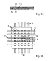
- FIGS. 3a An exemplary embodiment for the construction of a pressure-sensitive film is shown in FIGS. 3a in a sectional view and 3b in a plan view.
- the film essentially consists of two layers of crossed wires, 32 and 33, which are separated from one another by a rubber-like insulation layer 34, the insulation layer each having a hole 35 at the crossing points of the wires.
- the rubber-like insulation layer When pressure is exerted on the point 36, for example, the rubber-like insulation layer is pressed together so that the wires 37 of the layer 32 and 38 of the layer 33 touch within the hole 39. This closes a contact that irreversibly sets an electrical element of a circuit, not shown, in another state. In this way, each pressure point can be registered and displayed at any time on a monitor.
Abstract
Description
Die Erfindung betrifft ein Verfahren und eine Vorrichtung der im Oberbegriff der Ansprüche 1 und 6 angegebenen Art.The invention relates to a method and a device of the type specified in the preamble of
Die Funktion eines aus einer Druckschrift der Firma Siemens ("CEREC - Computer-Reconstruction, Druckvermerk: 0589) bekannt gewordenen Kompaktgerätes für die computergestützte Herstellung von Inlays, Onlays und Schalenverblendungen beruht auf einem optischen Vermessungsprinzip. Dabei wird mittels einer manuell positionierten Videoeinheit ein periodisches, bewegtes Muster paralleler Streifen auf den auszumessenden Zahn- oder Kieferbereich projiziert und die tiefentypischen Verzerrungen mit einer eingebauten Kamera aufgenommen. Nachteilig hierbei ist neben der manuellen Kameraführung vor allem die das Videobild überlagernde Darstellung der Meßinformation, die nicht unmittelbar auswertbar ist. Die Interpretation der resultierenden graphischen Muster stellt hohe Anforderungen an das räumliche Vorstellungsvermögen des behandelnden Zahnarztes. Wegen seiner transparenten Struktur und seiner spiegelnden Oberfläche muß der Zahnschmelz vor Anwendung des CEREC-Verfahrens mit einer dünnen Pulverschicht vorpräpariert sein.The function of one from a Siemens publication ("CEREC - Computer-Reconstruction, print note: 0589) compact device that has become known for the computer-assisted production of inlays, onlays and shell veneers is based on an optical measurement principle. Using a manually positioned video unit, a periodic, moving pattern of parallel stripes is projected onto the tooth or jaw area to be measured and the depth-typical distortions are recorded with a built-in camera. In addition to manual camera control, the disadvantage here is above all the display of the measurement information superimposed on the video image, which cannot be evaluated directly. The interpretation of the resulting graphic pattern places high demands on the spatial imagination of the dentist. Because of its transparent structure and its reflective surface, the tooth enamel must be prepared with a thin layer of powder before using the CEREC process.
Ein Verfahren und eine Vorrichtung gemäß dem ersten Teil der Ansprüche 1 und 6 sind aus der EP-A-0 054 785 bekannt.A method and a device according to the first part of
Der Erfindung liegt die Aufgabe zugrunde, ein Verfahren und eine Vorrichtung anzugeben, um mit computergestützten Mitteln die Paßgenauigkeit von Zahnersatz insbesondere im Hinblick auf den individuellen Biß des Patienten zu verbessern.The invention is based on the object of specifying a method and a device in order to improve the fitting accuracy of dentures with computer-aided means, in particular with regard to the individual bite of the patient.
Diese Aufgabe wird mit den kennzeichnenden Merkmalen der Ansprüche 1 bzw. 6 gelöst.This object is achieved with the characterizing features of
Die Erfindung beruht zunächst auf der Erkenntnis, daß - im Gegensatz zur bekannten zweidimensionalen visuellen Erfasssung - nur die dreidimensional abgetastete Oberfläche des Gegenbisses eine exakte Paßform des Bisses sicherstellen kann. Dabei werden von einer gedachten horizontalen Bezugsebene (x-y-Richtung) aus, die parallel zur Bißebene gelegen ist, Bereiche ermittelt, für die die Zahnoberflächen von Ober- und Unterkiefer gleiche Höhenwerte aufweisen, also bei geschlossenem Kiefer aufeinander zu liegen kommen und somit den Biß (Okklusion) bestimmen.The invention is initially based on the knowledge that - in contrast to the known two-dimensional visual detection - only the three-dimensionally scanned surface of the counterbite ensures an exact fit of the bite can. From an imaginary horizontal reference plane (xy-direction), which is parallel to the bite plane, areas are determined for which the tooth surfaces of the upper and lower jaw have the same height values, i.e. if the jaw is closed, they come to lie on one another and thus the bite ( Occlusion).
Bei der Erfindung lassen sich für den Fall, daß die Höhenwerte der Zahnoberflächen durch getrennte Messungen in unterschiedlichen Richtungen bestimmt werden müssen, durch entsprechene relative Verschiebung der in Speichern festgehaltenen Höhenwerte in Zuordnung zu den Koordinaten der x-y-Ebene abgleichen, um eine seitliche Verschiebung des Bisses zu kompensieren. Abgleichkriterium ist dabei eine Maximierung der Anzahl der übereinstimmenden ermittelten Höhenwerte, entsprechend einer maximalen Fläche von bei geschlossenem Biß aufeinander gelegenen Zahnbereichen.In the case of the invention, in the event that the height values of the tooth surfaces have to be determined by separate measurements in different directions, they can be adjusted by a corresponding relative shift of the height values stored in memories in association with the coordinates of the xy-plane by a lateral shift of the bite to compensate. The adjustment criterion is a maximization of the number of correspondingly determined height values, corresponding to a maximum area of tooth areas lying on one another when the bite is closed.
Auf diese Weise wird die optimale Bißlage für den Gesamtkiefer ermittelt, welche an und für sich bereits ausreichend wäre, um im Bereich von Zahndefekten durch Abnahme der Form der Zahnoberfläche des Gegenkiefers die maximale Ausdehnung des Zahnersatzes in Höhenrichtung zu bestimmen, so daß auch der Zahnersatz eine exakte Bißform bietet. Hierbei ist allerdings zunächst zu berücksichtigen, daß die im Biß aneinander anliegenden Bereiche der Zahnoberflächen des Gegenkiefers meist einander nur tangieren. Die übrigen Bereiche des Zahnersatzes sind also aus einem Modell zu ergänzen, welches eine Anzahl von natürlich wirkenden Zahnformen gespeichert enthält.In this way, the optimal bite position for the entire jaw is determined, which would in itself be sufficient to determine the maximum extent of the denture in the vertical direction in the area of tooth defects by decreasing the shape of the tooth surface of the opposing jaw, so that the denture also one offers exact bite shape. However, it must first be taken into account that the areas of the tooth surfaces of the opposing jaw that abut one another in the bite usually only touch one another. The remaining areas of the dentures are therefore to be supplemented from a model which contains a number of naturally acting tooth shapes stored.
Eine optimale Erzeugung einer Okklusion bietet das vorgenannte Verfahren jedoch noch nicht: Oftmals weicht nämlich der sich tatsächlich einstellende Biß eines Patienten von dem theoretisch sich einstellenden optimalen Biß ab.However, the aforementioned method does not yet offer optimal generation of an occlusion: namely, the actual bite of a patient deviates from the theoretically optimal bite.
Hierfür wird nun gemäß der Erfindung zusätzlich eine Anordnung verwendet, welche ein ebenes Bild des tatsächlichen Bisses des Patienten wiedergibt. Dazu sind elektronische Bißfolien bekannt, welche in Bereichen, in denen ein vorgegebener Anpreßdruck überschritten wird, jeweils ein Kontaktpaar einer Kontaktmatrix schließen und somit einem die sich kreuzenden Matrixleitungen scannend abtastenden Computer ein in einem Speicher festzuhaltendes Bild des tatsächlichen Bisses übermitteln.For this purpose, an arrangement is now additionally used according to the invention, which shows a flat image of the actual bite of the patient. For this purpose, electronic bite foils are known which, in areas in which a predetermined contact pressure is exceeded, each close one contact pair of a contact matrix and thus transmit an image of the actual bite to be stored in a memory to a computer scanning the intersecting matrix lines.
Nach der Erfindung wird dieses tatsächliche Bißbild nun als Bezug herangezogen für die Ausrichtung der in den entsprechenden Speichern festgehaltenen Abbildungen der Zahnoberflächen von Unter- und Oberkiefer. Durch relative Verschiebung der gespeicherten Höhenwerte von Ober- und Unterkiefer wird angestrebt, eine relative Position der Abbildungen von Ober- und Unterkiefer hinsichtlich der in dem Speicher festgehaltenen Daten in der Weise zu erzielen, daß die übereinstimmenden Höhenwerte, d.h. diejenigen Werte, welche beim im Speicher vorhandenen nachgebildeten Biß aufeinander zu liegen kommen, mit dem mittels der Bißfolie erfaßten realen Biß zusammenfallen, so daß die gespeicherte Nachbildung des Gebisses die Position des Gebisses beim tatsächlichen Biß einnimmt.According to the invention, this actual bite pattern is now used as a reference for the alignment of the images of the tooth surfaces of the lower and upper jaw recorded in the corresponding memories. By relative displacement of the stored height values of the upper and lower jaw, the aim is to achieve a relative position of the images of the upper and lower jaw with respect to the data recorded in the memory in such a way that the corresponding height values, i.e. those values which come to lie on one another in the simulated bite present in the memory coincide with the real bite detected by means of the bite sheet, so that the stored replica of the bit assumes the position of the bit in the actual bite.
Auf diese Weise gelingt es, ein durch scannende Abtastung gefundenes Bißbild, das nur zwei in getrennten Aufnahmen erfaßt werden kann, durch Prozessormittel über eine Verschiebung der Datenwerte im Speicher relativ zur Bißebene in die Position des realen Bisses zu überführen, so daß die für Gebißreparatur ermittelten Werte des Gegenbisses aus dieser realen Bißlage entnommen werden und der Zahnersatz entsprechend herstellbar ist.In this way it is possible to find a bite image found by scanning scanning, which is only two in separate images can be detected by processor means by moving the data values in the memory relative to the bite plane into the position of the real bite, so that the values of the opposite bite determined for denture repair are taken from this real bite position and the dentures can be produced accordingly.
Dabei ist insbesondere ein Scanner zur optischen Abtastung des interessierenden Kieferbereiches mit einer Tiefenmeßeinrichtung verbunden, wobei die Ansteuersignale für den Scanner gleichzeitig Adreßwerte eines Meßwertspeichers bilden. Eine angeschlossene Auswerteeinheit dient der Ermittlung und dreidimensionalen Darstellung der Oberflächenkoordinaten der vermessenen Ober- und Unterkieferzähne. Okklusion und Artikulation werden über eine mit einer drucksensitiven Bißfolie versehenen, vorzugsweise U-förmig gestalteten Bißgabel festgestellt. Die durch den Zahndruck ausgelösten Kontakte werden den Abbildern der Ober- und Unterkieferzähne überlagert. Die Relativlage der Abbilder des Unterkiefers, des Oberkiefers und des Bißabdruckes ist vorzugsweise mittels Maussteuerung veränderbar, so daß eine eindeutige, der Okklusion entsprechende Zuordnung der Ober- und der Unterkieferzähne einstellbar ist. Auf diese Weise lassen sich auch bei dem Patienten fehlende Zahnbereiche im Hinblick auf ihre vorhandenen Antipoden paßgenau ergänzen.In particular, a scanner for optically scanning the jaw region of interest is connected to a depth measuring device, the control signals for the scanner simultaneously forming address values of a measured value memory. A connected evaluation unit is used to determine and three-dimensional display of the surface coordinates of the measured upper and lower teeth. Occlusion and articulation are determined using a bite fork, preferably U-shaped, with a pressure-sensitive bite sheet. The contacts triggered by the tooth pressure are superimposed on the images of the upper and lower teeth. The relative position of the images of the lower jaw, the upper jaw and the bite impression can preferably be changed by mouse control, so that a clear assignment of the upper and lower jaw teeth corresponding to the occlusion can be set. In this way, missing tooth areas can also be added to the patient in terms of their existing antipodes.
Im Hinblick auf Zahnbereiche, die nicht Teil der Okklusionen sind, kann dabei ergänzend auf gespeicherte Ideal- oder Mittelwertformen entsprechender Größe unter Berücksichtigung eines angepaßten Übergangs zurückgegriffen werden.With regard to tooth areas that are not part of the occlusion, stored ideal or mean value forms of corresponding size can also be used, taking into account an adapted transition.
Eine sich anschließende Rechnereinheit verarbeitet diese graphisch ermittelten Überlagerungen zu Oberflächenkoordinaten des herzustellenden Zahnersatzzteiles. Dafür werden neben den ausgemessenen Zahnkonturen und der individuellen Okklusion vorzugsweise auch abgespeicherte Konturen eines gleichartigen defektlosen Idealzahnes oder einer entsprechenden Zahngruppe zugrundegelegt. Über einen Wandler werden die ermittelten Daten an das Format der Eingangsdaten einer numerisch gesteuerten Werkzeugmaschine angepaßt. Diese dient dem automatischen Ausfräsen und gegebenenfalls dem Schleifen und Polieren des Zahnersatzteiles.A subsequent computer unit processes these graphically determined superpositions into surface coordinates of the dental prosthesis part to be produced. For this purpose, in addition to the measured tooth contours and the individual occlusion, preferably also stored contours of a similar defect-free ideal tooth or a corresponding group of teeth are used as a basis. The determined data are adapted to the format of the input data of a numerically controlled machine tool via a converter. This is used for automatic milling and, if necessary, for grinding and polishing the dental prosthetic item.
Entsprechend einer vorteilhaften Weiterbildung der Erfindung ist zur Führung des Meßstrahles über den zu vermessenden Kieferbereich mindestens ein mittels der Ansteuermittel scannend bewegbarer Umlenkspiegel oder/und mindestens ein Prisma vorgesehen. Zur Bewegung dient dabei bevorzugt eine Doppelschlittenführung nach dem Prinzip eines Plotters.According to an advantageous development of the invention, at least one deflecting mirror or / and at least one prism is provided for guiding the measuring beam over the jaw region to be measured by scanning the control means. A double slide guide according to the principle of a plotter is preferably used for the movement.
Die Ansteuermittel erzwingen einen bestimmten Bewegungsablauf der Umlenkelemente und damit ein Durchmustern der Oberfläche. Da den Ansteuersignalen in eindeutiger Weise ebene Koordinaten (x; y) der Projektion des Meßstrahles auf den auszumessenden Zahn- oder Kieferbereich zugeordnet sind, entspricht jedem Wertepaar Ansteuersignal/Meßwert [(x; y)/(z)] genau ein Raumpunkt. Die Speicherung der Wertepaare erfolgt vorteilhafterweise in einem RAM-Festwertspeicher , wobei die Ansteuersignale die Adreßwerte bilden. Damit ist die Voraussetzung für eine bequeme Weiterverarbeitung der Daten gegeben.The control means force a certain course of movement of the deflection elements and thus a patterning of the surface. Since the control signals are uniquely assigned plane coordinates (x; y) of the projection of the measurement beam onto the tooth or jaw area to be measured, each control signal / measurement value [(x; y) / (z)] corresponds to exactly one point in space. The pairs of values are advantageously stored in a RAM read-only memory, the control signals forming the address values. This is the prerequisite for convenient further processing of the data.
Die Ermittlung der Abstandsmeßwerte erfolgt im wesentlichen nach bekannten optischen Verfahren, beispielsweise dem Triangulationsverfahren oder dem Verfahren der dynamischen Fokussierung. Dementsprechend ist der Meßstrahl ein Laserstrahl oder ein Lichtstrahl, dessen Wellenlänge vorzugsweise im Infrarot-Bereich liegt. Als lichtelektrischer Empfänger ist vor allem eine Fotodetektoranordnung aber auch ein CCD-Target geeignet.The distance measured values are essentially determined using known optical methods, for example the triangulation method or the dynamic focusing method. Accordingly, the measuring beam is a laser beam or a light beam, the wavelength of which is preferably in the infrared range. A photodetector arrangement, but also a CCD target, is particularly suitable as the photoelectric receiver.
Vorteilhafte Weiterbildungen der Erfindung sind in den Unteransprüchen gekennzeichnet bzw. werden nachstehend zusammen mit der Beschreibung der bevorzugten Ausführung der Erfindung anhand der Figuren näher dargestellt. Es zeigen:
- Figur 1 eine Draufsicht einer Abtastvorrichtung in schematisierter Darstellung,
Figur 2 eine Baugruppenübersicht zur Meßwertverarbeitung für die automatische Herstellung eines Zahnersatzteiles sowieFigur 3 eine Draufsicht auf ein Ausführungsbeispiel einer "elektronischen Bißfolie".
- FIG. 1 shows a top view of a scanning device in a schematic illustration,
- Figure 2 is an assembly overview for processing measured values for the automatic production of a dental prosthetic item and
- Figure 3 is a plan view of an embodiment of an "electronic bite sheet".
Die in Figur 1 wiedergegebene Abtastvorrichtung besteht im wesentlichen aus zwei parallelen Führungen in Form von Schienen 1 und 2, die durch in Form von Abstandhaltern ausgebildeten Streben 3 und 4 starr miteinander verbunden sind, einem auf den Schienen 1 und 2 beweglichen, eine Traverse bildenen Wagen 5 und einem auf dieser Traverse verschieblichen Läufer 6, welcher auf dem Wagen 5 senkrecht zum Verlauf der Schienen 1 und 2 verschiebbar ist. Die Traverse 6 kann durch seine eigene Verschiebbarkeit auf dem Wagen 5 und durch die Verschiebbarkeit des Wagens 5 jeden Punkt einer zwischen den Schienen 1 und 2 aufgespannten Ebene erreichen. Über einen mit dem Läufer 6 fest verbundenen Strahlführungskanal 7, der etwa die Länge einer Schiene 1 bzw. 2 aufweist, ist in einem gemeinsamen Gehäuse sowohl die Strahlungsquelle als auch der Empfänger des Meßstrahles 8 mit einer auf dem Läuferelement 6 befindlichen Meßeinheit 10 verbunden. Strahlungsquelle und Empfänger werden demzufolge mit dem Läufer mitbewegt. Die Meßeinheit 10 bildet eine komplette Entfernungsmeßeinrichtung, welche den Abstand eines unterhalb der Meßeinheit befindlichen Hindernisses ermittelt und ein Signal ausgibt, welches repräsentativ für diese, auf einen Punkt des Läufers bezogene Entfernung, ist. Bei einem nach dem Prinzip der dynamischen Fokussierung arbeitenden System, wie es dem Abtaster eines CD-Spielers entspricht, dynamisch nachgeführt wird und die bei Scharfeinstellung sich ergebende Positionsinformation als Abstandsmeßwert übermittelt.The scanning device shown in FIG. 1 essentially consists of two parallel guides in the form of
Die Ansteuerung des Wagens 5 und des Läufers 6 erfolgt entsprechend einem Plotter über miniaturisierte elektrische Antriebsmotore. Figur 1 zeigt zwei unterschiedliche Positionen der mit Wagen 5 und Läufer 6 verschobenen Meßanordnung. Der Antrieb des Wagens 5 und des Läufers 6 kann beispielsweise über Schrittmotoren 11 und 12 vorgenommen werden, deren Mitnehmer 13 und 14 jeweils eine der Schienenlänge bzw. der Wagenlänge angepaßte, spindelförmige Schnecke 15 bzw. 16 in Drehung versetzen, wobei der Wagen 5 und der Läufer 6 mittels Zahnstangen in die Schnecken 15 und 16 eingreifen und dadurch bewegt werden. Die Spannungsverläufe der Steuerspannungen für die Motoren 11 und 12, die den einzustellenden x/y-Werten der jeweils einzuhaltenden Position zugeordnet sind, werden von einer externen Baugruppe 17 her zugeführt und in Form von codierten Steuersignalen 17a (x-Position) und 17b (y-Position) codiert zugeführt, so daß sie vorteilhafterweise gleichzeitig die Adressenwerte für die spätere Speicherung der ermittelten Meßwerte (z-Position), die am Ausgang 17c erhalten werden, bilden können. Der Läufer 6 mit dem Meßsystem 10 und der Traverse des Wagens 5 entspricht in seiner Ausgestaltung der Führung eines Abtasters bei einem üblichen CD-Spieler, so daß die entsprechenden am Markt erhältlichen miniaturisierten Bauelemente großteils bei der Konstruktion benutzt werden können.The control of the
Die Abstandsabtastung kann auch nach anderen physikalischen Verfahren erfolgen, wobei das der Triangulation zu nennen ist. Günstig sind auch solche Verfahren, welche ein Echosignal erzeugen, dessen Verzögerung einen Rückschluß auf den Tiefenabstand zuläßt und beispielsweise mittels Ultraschall oder Mikrowelle arbeiten.The distance can also be scanned using other physical methods, which is to be called the triangulation. Such methods are also favorable which generate an echo signal, the delay of which permits conclusions to be drawn about the depth distance and which operate, for example, by means of ultrasound or a microwave.
In Figur 2 ist eine Baugruppenübersicht zur Meßwertverarbeitung für die automatische Herstellung eines Zahnersatzteiles, insbesondere einer Krone oder einer Brücke, unter Berücksichtigung der Okklusion und der Artikulation wiedergegeben. Eine Abtastvorrichtung 18, beispielsweise auf der Basis der in Figur 1 dargestellten Bauart, wird von einer externen Steuerung 19 derart angesteuert, daß der Meßstrahl mit einem bestimmten Bewegungsablauf über das zu vermessende Zahngebiet geführt wird. Jedem Ansteuersignal ist dabei ein eindeutiger Punkt der Scanningebene zugeordnet. Die Steuerung 19 ist über eine Codiereinrichtung 20 mit dem Adresseneingang 21 eines RAM-Festwertspeichers 22 verbunden, während die Meßsignale über eine Meßwertermittlung 23 direkt in die zugeordneten Speicherplätze 24 gelangen. Ein mit dem Speicher 22 verbundener Rechner 25 verarbeitet die ermittelten und gespeicherten Oberflächenkoordinaten des Oberkieferbereiches und des zugeordneten Unterkieferbereiches, wodurch beide Bereiche als dreidimensionale Grafiken auf einem angeschlossenen Monitor 26 darstellbar sind. An den Monitor 26 angeschlossen ist außerdem eine U-förmig gestaltete Bißgabel 27 aus drucksensitiver Folie, welche zur Feststellung der terminalen Okklusion und der Artikulation dient. Die ermittelten Druckpunkte bzw. Druckzonen werden auf dem Monitor 26 im gleichen Maßstab wie der Oberkiefer- und der Unterkieferbereich abgebildet. Die Oberfläche der Bißgabel 27 ist zur besseren Positionierung im Munde in ein Wachsbad getaucht worden. Die Sterilisation der Bißgabel 27 ist problemlos mit Dampfstrahler und/oder Thermodesinfektor bzw. in den praxisüblichen Sterilisatoren durchführbar. Auch die Beschichtung mit einer neuen Wachsschicht ist ohne großen Aufwand möglich. Über eine Maussteuerung 28 wird das Abbild der Bißgabel 27 mit den entsprechenden Punkten des Unterkieferabbildes und des Oberkieferabbildes in Deckung gebracht. Eine Auswerteeinheit 29 zur Ermittlung der Konturen des herzustellenden Zahnersatzteiles ist sowohl mit dem Rechner 25 als auch mit dem Monitor 26 und dem Speicher 22 verbunden, wobei die Monitorgrafik, die eine eindeutige Zuordnung von Ober- und Unterkiefer wiedergibt, in der Weise berücksichtigt wird, daß sich die zu ermittelnden Konturen in die gegebene Okklusion bzw. Artikulation einfügen. Gleichzeitig werden die in dem Speicher 22 enthaltenen Daten eines defektlosen Idealzahnes oder Idealzahngebietes zur Vervollständigung der fehlenden Begrenzungsflächen des Zahnersatzes herangezogen. Die Ausgangsdaten der Auswerteeinheit 29 charakterisieren einen vermessenen Negativabdruck eines Zahndefektes bzw. einer Zahnlücke, der nach dentologischen Gesichtspunkten unter Berücksichtigung der Okklusion und der Artikulation derart vervollständigt wurde, daß die Umrisse des herzustellenden Zahnersatzes damit gegeben sind. Diese Daten werden einem Wandler zur Anpassung an das Format der Eingangsdaten einer numerisch gesteuerten Werkzeugmaschine zugeführt und dienen dann zur Ansteuerung der Werkzeugmaschine 31, insbesondere einer Fräsmaschine, welche das Zahnersatzteil in individuell passender Form aus einem Rohling ausfräst.FIG. 2 shows an assembly overview for processing measured values for the automatic production of a tooth replacement part, in particular a crown or a bridge, taking into account the occlusion and the articulation. A
Bei der so dargestellten Vorrichtung zur individuellen Herstellung eines Zahnersatzteiles, insbesondere einer Krone oder eines Gebißteiles unter Verwendung eines, insbesondere optischen, Systems zur Zahndefekterkennung und einer numerisch gesteuerten Werkzeugmaschine, wobei die Steuersignale computergestützt von dem vermessenen Zahndefekt abgeleitet sind, sind somit vorgesehen: eine Ansteuereinheit (19) zur, insbesondere scannenden, Führung des Meßstrahles (8) und Erzeugung von dreidimensionalen Abbildern von einander zugewandten Bereichen von Ober- und Unterkiefer durch punktweise Abtastung, ein Meßwertspeicher (22) für die Speicherung der Abbilder von Unter- und Oberkiefer in Form von einzelnen, den Meßpunkten entsprechenden Meßwertdaten als erster Datensatz, eine drucksensitive Bißfolie (27), eine Einheit zur zweidimensionalen Erfassung von Bereichen der Bißfolie, in denen bei einem Probebiß des Patienten ein vorgegebener Anpreßdruck überschritten wird, und Speicherung dieser Koordinatenwerte als Daten in einem zweiten Datensatz, eine Rechnereinheit (25) zur Ermittlung von Bereichen, in denen die vertikalen Komponenten, unter Berücksichtigung der horizontalen Bezugsebenen für die jeweils für Ober-und Unterkiefer und der unterschiedlichen Meßrichtung, getrennt erfaßten Meßwerte eine übereinstimmende Höhenkomponente haben, und Speicherung dieser zweidimensionalen Daten in einem dritten Datensatz, elektronische Komponenten zur möglichst weitgehenden Überlagerung des zweiten und dritten Datensatzes, wobei die Daten des zweiten Datensatzes dem dritten Datensatz bezüglich ihrer Kordinatenwerte möglichst vollständig einbeschrieben sein sollen, insbesondere durch gleichmäßige Änderung der horizontalen Koordinatendaten für alle Punkte des zweiten Datensatzes relativ zu den Koordinaten des dritten Datensatzes, sowie das Ergänzen von im Ober- bzw. Unterkiefer fehlenden und daher nicht erfaßten Zahnbereichen entsprechend den Koordinaten der in diesen Bereichen ermittelten Höheninformationen des Gegenkiefers wieder unter Berücksichtigung der horizontalen Bezugsebenen.In the device for the individual production of a tooth replacement part, in particular a crown or denture part, using an, in particular optical, system for tooth defect detection and a numerically controlled machine tool, the control signals being derived from the measured tooth defect in a computer-assisted manner, the following are thus provided: a control unit (19) for, in particular scanning, guiding the measuring beam (8) and generating three-dimensional images of mutually facing regions of the upper and lower jaw by point-by-point scanning, a measured value memory (22) for storing the images of the lower and Upper jaw in the form of individual measured value data corresponding to the measurement points as the first data record, a pressure-sensitive bite sheet (27), a unit for two-dimensional detection of areas of the bite sheet in which a predetermined contact pressure is exceeded during a test bite of the patient, and storage of these coordinate values as data in a second data set, a computer unit (25) for determining areas in which the vertical components, taking into account the horizontal reference planes for the measured values separately recorded for the upper and lower jaw and the different measuring direction, have a corresponding height component, and storing them two-dimensional data in a third data set, electronic components for superimposing the second and third data sets as far as possible, the data of the second data set inscribing the coordinate values as completely as possible with respect to their coordinate values n should be, in particular by uniformly changing the horizontal coordinate data for all points of the second data set relative to the coordinates of the third data set, as well as supplementing tooth areas that are missing in the upper or lower jaw and therefore not recorded in accordance with the coordinates of the height information determined in these areas of the opposite jaw again taking into account the horizontal reference planes.
Auf diese Weise lassen sich auch fehlende Bereiche entsprechend dem individuellen Biß ergänzen. Die zwischen den Okklusionen und den restlichen Zahnbereichen vorhandenen Bezirke werden in optimaler Anpassung der Übergangsbereiche nach vorhandenen (gespeicherten) Zahnmustern ergänzt.In this way, missing areas can be supplemented according to the individual bite. The areas between the occlusions and the remaining tooth areas are optimally adapted to the transition areas added to existing (saved) tooth samples.
Ein Ausführungsbeispiel für den Aufbau einer drucksensitive Folie ist in den Figuren 3a in einem Schnittbild und 3b in einer Draufsicht wiedergegeben. Die Folie besteht im wesentlichen aus zwei Schichten gekreuzter Drähte,32 und 33, die durch eine gummiartige Isolationsschicht 34 voneinander getrennt sind, wobei die Isolationsschicht an den Kreuzungspunkten der Drähte jeweils ein Loch 35 aufweist. Bei Druck auf die Stelle 36 beispielsweise wird die gummiartige Isolationsschicht zusammengepreßt, so daß sich die Drähte 37 der Schicht 32 und 38 der Schicht 33 innerhalb des Loches 39 berühren. Dadurch wird ein Kontakt geschlossen, der ein elektrisches Element einer nicht dargestellten Schaltung irreversibel in einen anderen Zustand setzt. Auf diese Weise läßt sich jeder Druckpunkt registrieren und zu einem beliebigen Zeitpunkt über einen Monitor darstellen.An exemplary embodiment for the construction of a pressure-sensitive film is shown in FIGS. 3a in a sectional view and 3b in a plan view. The film essentially consists of two layers of crossed wires, 32 and 33, which are separated from one another by a rubber-
Die Erfindung beschränkt sich in ihrer Ausführung nicht auf das vorstehend angegebene bevorzugte Ausführungsbeispiel. Vielmehr ist eine Anzahl von Varianten denkbar, wie sie in den abhängigen Ansprüchen augegeben sind.The embodiment of the invention is not limited to the preferred exemplary embodiment specified above. Rather, a number of variants are conceivable, as they are given in the dependent claims.
Claims (16)
- A process for preparing individually a dental prosthesis, more particularly a crown or a denture part by the use of a system for detecting dental defects and a numerically controlled machine tool, the control signals for the machine tool being derived from the dental defect measured, with the aid of a computer, characterised by the following process steps:
guiding a measuring beam (8) across a dental zone to be measured and producing accordingly a three-dimensional picture of facing dental regions of the upper and lower jaw by scanning, point by point, the coordinates of the biting plane (xy-plane) or of a reference plane parallel to the biting plane, and ascertaining the altitude values (z- or -z-direction) associated with the x,y-coordinates,
storing the three-dimensional pictures of the upper and lower jaw in the form of individual altitude values, corresponding to the x,y-coordinates, as first or second partial data of a first set of data,
two-dimensional recording of regions, in which a predetermined contact pressure is exceeded by a sample bite taken from the patient, and storing the coordinate values of the biting plane (xy-plane) associated with said regions, as a second set of data,
detecting regions of the biting plane (xy-plane), in which the altitude values (z- or -z-direction) of the first and second partial data of the first data set conform in respect of identical x,y-coordinate values, while taking account of the relevant direction of measurement, and storage of the coordinate values of the biting plane, associated with said regions, as a third set of data,
superimposing the data of the second and third data set as much as possible such that the values of the second data set coincide with the values of the third data set as fully as possible, more particularly by changing the coordinates of the biting plane in respect of all the points of the second data set, relative to the coordinates of the third data set, the coordinates of the points, in respect of which the values of the second and third data set coincide after superposition, forming a fourth set of data, as well as supplementing missing altitude values (z- or -z-direction) of the upper or lower jaw within the region of dental defects by the corresponding altitude values of the opposite jaw of the first data set, obtained in respect of the respective x,y-coordinates in said region, and storage of the coordinate values as a fifth set of data, the altitude values being based on the biting plane (xy-plane). - A process according to claim 1, characterised by the input of the coordinates of an area of the biting plane in which there is a dental defect, at least as part of the fifth set of data.
- A process according to either claim 1 or 2, characterised in that the values of the second, third, fourth and/or fifth data set are stored as logical values and linked during the processing by means of logical AND-interconnection.
- A process according to any one of claims 1 to 3, characterised in that, when the data of the second and third data set are superimposed, various third data sets, produced in respect of different positions of the upper and lower jaw relative to one another, are successively compared with the second data set, and that data set is chosen as fourth data set, in respect of which there is a maximum conformity of the data of the third data set with the second data set.
- A process according to any one of claim 2 to 4, characterised by supplementing coordinate values for regions of the biting plane, in which there is a dental defect, which coordinate values form a fifth data set, by coordinate values of a dental cast contained in a cast memory, which coordinates values form a sixth data set, while continuously connecting them to the measured and processed altitude values.
- A device for carrying out the process according to any one of the preceding claims, characterised by a measuring arrangement comprising a control unit (19) for guiding a measuring beam (8), more particularly by scanning, across a dental region to be measured, and for producing accordingly a three-dimensional picture of facing dental regions of the upper and lower jaw, by the point-by-point scanning of the coordinates of the biting plane (xy-plane) or of a reference plane parallel to the biting plane, and determining the associated altitude values (z- or -z-direction),
a measurement memory (22) for storing the three-dimensional pictures of the lower and upper jaw in the form of individual coordinates corresponding to the measuring points, as first or second partial data of a first data set,
an arrangement (27) for detecting the bite pressure in the biting plane,
a unit for the two-dimensional recording of regions of the arrangement for detecting the bite pressure, in which regions a predetermined contact pressure is exceeded when a bite sample is taken from the patient, and storage of the results obtained as a function of the associated x,y-coordinate values of the biting plane (xy-plane), as a second set of data,
a computing unit (25) for detecting the regions of the biting plane (xy-plane), in which the altitude values (z- or -z-direction) of the first and second partial data of the first data set, in the case of the upper and lower jaw respectively, conform in respect of identical x,y-coordinate values, while taking account of the respective measuring direction, and for storing the results obtained as a function of the associated coordinate values of the biting plane in the measurement memory, as at least a third set of data,
an adjustment unit for as great as possible a super-position of the data of the second and third data set, the coordinate values of the second data set being intended to coincide with the coordinate values of the third data set as fully as possible, more particularly by changing the x,y-coordinates of the biting plane, in respect of all the points of the second data set, relative to the x,y-coordinates of the third data set, as well as
a unit for supplementing altitude values in the upper or lower jaw within the region of dental defects by altitude values of the opposite jaw of the first data set, which altitude values were detected in respect of the relevant x,y-coordinates in said region, as a fifth set of data, the altitude values being based on the biting plane. - A device according to claim 6, characterised in that an input device is provided for inputting a coordinate region of the biting plane, in which there is a dental defect.
- A device according to claim 7, characterised in that the adjustment unit and/or the supplementing unit have means for the logical AND-interconnection of the values of the second, third, fourth and/or fifth data set as stored logical values.
- A device according to any one of claims 6 to 8, characterised by an approximation arrangement for supplementing altitude values within the regions of the biting plane, in which there is a dental defect, by the corresponding altitude values of a dental cast contained in a cast memory, while continuously connecting them to the supplemented altitude values.
- A device according to any one of claims 6 to 9, characterised by a laser for producing the measuring beam (8).
- A device according to any one of claims 6 to 9, characterised in that the wavelength of the measuring beam (8) is within the infra-red range.
- A device according to any one of claims 6 to 11, characterised in that photo detectors are provided to receive and detect measured values, to which detectors a differential gain circuit is connected.
- A device according to any one of claim 6 to 11, characterised in that a CCD-target is provided as receiver.
- A device according to any one of claims 6 to 13, characterised in that the arrangement which ascertains the bite pressure is a pressure sensitive biting film, (27).
- A device according to claim 14, characterised in that the pressure-sensitive biting film (27) is in the form of a U-shaped bite registration holder.
- A device according to any one of the preceding claims, characterised by a mouse control (28) and a display, the relative position of the pictures in the form of data sets being changeable with the help of a mouse control (28) and the evaluation of the adjustment being effected by means of a display which shows the data sets, in each case in the superimposed state.
Applications Claiming Priority (2)
| Application Number | Priority Date | Filing Date | Title |
|---|---|---|---|
| DE3932149 | 1989-09-22 | ||
| DE3932149 | 1989-09-22 |
Publications (2)
| Publication Number | Publication Date |
|---|---|
| EP0491808A1 EP0491808A1 (en) | 1992-07-01 |
| EP0491808B1 true EP0491808B1 (en) | 1993-09-01 |
Family
ID=6390246
Family Applications (1)
| Application Number | Title | Priority Date | Filing Date |
|---|---|---|---|
| EP90914051A Expired - Lifetime EP0491808B1 (en) | 1989-09-22 | 1990-09-24 | Process and device for the production of an individual tooth replacement part |
Country Status (5)
| Country | Link |
|---|---|
| EP (1) | EP0491808B1 (en) |
| AU (1) | AU6435590A (en) |
| DE (3) | DE4091623D2 (en) |
| ES (1) | ES2043387T3 (en) |
| WO (1) | WO1991003989A1 (en) |
Families Citing this family (3)
| Publication number | Priority date | Publication date | Assignee | Title |
|---|---|---|---|---|
| US5273429A (en) * | 1992-04-03 | 1993-12-28 | Foster-Miller, Inc. | Method and apparatus for modeling a dental prosthesis |
| DE4214876C2 (en) * | 1992-05-05 | 2000-07-06 | Kaltenbach & Voigt | Optical measurement of teeth without a matt surface treatment |
| US9408686B1 (en) | 2012-01-20 | 2016-08-09 | Conformis, Inc. | Devices, systems and methods for manufacturing orthopedic implants |
Family Cites Families (4)
| Publication number | Priority date | Publication date | Assignee | Title |
|---|---|---|---|---|
| ATE14073T1 (en) * | 1980-12-24 | 1985-07-15 | Werner H Dr Med Dent Moermann | PROCESSES FOR THE MANUFACTURE OF MEDICAL AND DENTAL TECHNOLOGY ALLOPLASTIC, ENDO- AND EXOPROSTHETIC FITTING BODY. |
| FR2525103B1 (en) * | 1982-04-14 | 1985-09-27 | Duret Francois | IMPRESSION TAKING DEVICE BY OPTICAL MEANS, PARTICULARLY FOR THE AUTOMATIC PRODUCTION OF PROSTHESES |
| US4663720A (en) * | 1984-02-21 | 1987-05-05 | Francois Duret | Method of and apparatus for making a prosthesis, especially a dental prosthesis |
| US4734034A (en) * | 1985-03-29 | 1988-03-29 | Sentek, Incorporated | Contact sensor for measuring dental occlusion |
-
1990
- 1990-09-24 DE DE90DE9000729D patent/DE4091623D2/en not_active Expired - Lifetime
- 1990-09-24 DE DE90914051T patent/DE59002586D1/en not_active Expired - Lifetime
- 1990-09-24 EP EP90914051A patent/EP0491808B1/en not_active Expired - Lifetime
- 1990-09-24 AU AU64355/90A patent/AU6435590A/en not_active Abandoned
- 1990-09-24 WO PCT/DE1990/000729 patent/WO1991003989A1/en active IP Right Grant
- 1990-09-24 ES ES90914051T patent/ES2043387T3/en not_active Expired - Lifetime
- 1990-09-24 DE DE19904091623 patent/DE4091623A1/en not_active Withdrawn
Also Published As
| Publication number | Publication date |
|---|---|
| DE4091623A1 (en) | 1992-10-08 |
| ES2043387T3 (en) | 1993-12-16 |
| DE4091623D2 (en) | 1992-10-08 |
| WO1991003989A1 (en) | 1991-04-04 |
| DE59002586D1 (en) | 1993-10-07 |
| AU6435590A (en) | 1991-04-18 |
| EP0491808A1 (en) | 1992-07-01 |
Similar Documents
| Publication | Publication Date | Title |
|---|---|---|
| DE3723555C2 (en) | Process for the production of dentures | |
| EP1762821B1 (en) | Device and method for producing denture parts | |
| EP2039321B1 (en) | Surface recording and generation | |
| EP0250993B1 (en) | Method and apparatus for the three-dimensional representation and determination of prepared teeth | |
| DE3312245A1 (en) | DEVICE FOR DIAGNOSIS OF UNDERJACK MOTION | |
| EP1406555B1 (en) | Method and device for the there-dimensional determination and digitisation of a dental model | |
| DE10355384A1 (en) | Method and device for aligning an X-ray source and a detector at different distances between the source and the image | |
| CH688471A5 (en) | Engraving and method for its operation | |
| WO2000010482A1 (en) | Method for the computer-controlled production of dentures | |
| EP2457058B1 (en) | Generating a total data set | |
| WO1991003980A1 (en) | Device for scanning a region of a buccal cavity | |
| EP1710536B1 (en) | Method for determining the shape of a body in three dimensions | |
| EP0447531B1 (en) | Process and device for the three-dimensional optical measurement, especially of teeth in patients' buccal cavities | |
| DE3810455A1 (en) | Method and device for the contactless, three-dimensional measurement of an irregular body | |
| EP0455855B1 (en) | Method and device for the manufacture of medical in particular dental, prosthesis | |
| DE2259762B2 (en) | Process for the automatic evaluation of stereo images | |
| EP0491808B1 (en) | Process and device for the production of an individual tooth replacement part | |
| WO1991003988A1 (en) | Device for the production of tooth replacement parts | |
| EP3195826B1 (en) | Method for creating a digital dental model | |
| DE4415659C1 (en) | Computer-aided mfr. of articles using optically measured object data | |
| DE3123526C2 (en) | Method for one to three-dimensional measurement of jaw and jaw joint movements and arrangement for carrying out the method | |
| DE19735112A1 (en) | Method of setting freely programmable patient X=ray recording system | |
| DE4239039C2 (en) | Method for acquiring data from bond pads for controlling a bonder | |
| DE2641965A1 (en) | TEST DEVICE FOR A PHOTOGRAMMETRICAL INSTRUMENT | |
| DE4314602A1 (en) | Fitting or dental prosthesis to remaining stump |
Legal Events
| Date | Code | Title | Description |
|---|---|---|---|
| PUAI | Public reference made under article 153(3) epc to a published international application that has entered the european phase |
Free format text: ORIGINAL CODE: 0009012 |
|
| 17P | Request for examination filed |
Effective date: 19920422 |
|
| AK | Designated contracting states |
Kind code of ref document: A1 Designated state(s): CH DE ES FR GB IT LI |
|
| 17Q | First examination report despatched |
Effective date: 19921229 |
|
| GRAA | (expected) grant |
Free format text: ORIGINAL CODE: 0009210 |
|
| AK | Designated contracting states |
Kind code of ref document: B1 Designated state(s): CH DE ES FR GB IT LI |
|
| REF | Corresponds to: |
Ref document number: 59002586 Country of ref document: DE Date of ref document: 19931007 |
|
| ITF | It: translation for a ep patent filed |
Owner name: BARZANO' E ZANARDO MILA |
|
| REG | Reference to a national code |
Ref country code: ES Ref legal event code: FG2A Ref document number: 2043387 Country of ref document: ES Kind code of ref document: T3 |
|
| ET | Fr: translation filed | ||
| GBT | Gb: translation of ep patent filed (gb section 77(6)(a)/1977) |
Effective date: 19931201 |
|
| PLBE | No opposition filed within time limit |
Free format text: ORIGINAL CODE: 0009261 |
|
| STAA | Information on the status of an ep patent application or granted ep patent |
Free format text: STATUS: NO OPPOSITION FILED WITHIN TIME LIMIT |
|
| 26N | No opposition filed | ||
| REG | Reference to a national code |
Ref country code: GB Ref legal event code: IF02 |
|
| PGFP | Annual fee paid to national office [announced via postgrant information from national office to epo] |
Ref country code: ES Payment date: 20090928 Year of fee payment: 20 |
|
| PGFP | Annual fee paid to national office [announced via postgrant information from national office to epo] |
Ref country code: GB Payment date: 20090922 Year of fee payment: 20 Ref country code: CH Payment date: 20090923 Year of fee payment: 20 |
|
| PGFP | Annual fee paid to national office [announced via postgrant information from national office to epo] |
Ref country code: DE Payment date: 20091002 Year of fee payment: 20 |
|
| PGFP | Annual fee paid to national office [announced via postgrant information from national office to epo] |
Ref country code: IT Payment date: 20090924 Year of fee payment: 20 |
|
| REG | Reference to a national code |
Ref country code: CH Ref legal event code: PL |
|
| REG | Reference to a national code |
Ref country code: GB Ref legal event code: PE20 Expiry date: 20100923 |
|
| PG25 | Lapsed in a contracting state [announced via postgrant information from national office to epo] |
Ref country code: GB Free format text: LAPSE BECAUSE OF EXPIRATION OF PROTECTION Effective date: 20100923 |
|
| PGFP | Annual fee paid to national office [announced via postgrant information from national office to epo] |
Ref country code: FR Payment date: 20091005 Year of fee payment: 20 |
|
| REG | Reference to a national code |
Ref country code: ES Ref legal event code: FD2A Effective date: 20120510 |
|
| PG25 | Lapsed in a contracting state [announced via postgrant information from national office to epo] |
Ref country code: ES Free format text: LAPSE BECAUSE OF EXPIRATION OF PROTECTION Effective date: 20100925 |
|
| PG25 | Lapsed in a contracting state [announced via postgrant information from national office to epo] |
Ref country code: DE Free format text: LAPSE BECAUSE OF EXPIRATION OF PROTECTION Effective date: 20100924 |