EP0482842A1 - Method and equipment for automatic production of reinforcing steels for concrete elements - Google Patents
Method and equipment for automatic production of reinforcing steels for concrete elements Download PDFInfo
- Publication number
- EP0482842A1 EP0482842A1 EP91309653A EP91309653A EP0482842A1 EP 0482842 A1 EP0482842 A1 EP 0482842A1 EP 91309653 A EP91309653 A EP 91309653A EP 91309653 A EP91309653 A EP 91309653A EP 0482842 A1 EP0482842 A1 EP 0482842A1
- Authority
- EP
- European Patent Office
- Prior art keywords
- reinforcing
- reinforcing steel
- reinforcement
- steels
- longitudinal
- Prior art date
- Legal status (The legal status is an assumption and is not a legal conclusion. Google has not performed a legal analysis and makes no representation as to the accuracy of the status listed.)
- Granted
Links
Images

Classifications
-
- B—PERFORMING OPERATIONS; TRANSPORTING
- B21—MECHANICAL METAL-WORKING WITHOUT ESSENTIALLY REMOVING MATERIAL; PUNCHING METAL
- B21F—WORKING OR PROCESSING OF METAL WIRE
- B21F11/00—Cutting wire
-
- B—PERFORMING OPERATIONS; TRANSPORTING
- B21—MECHANICAL METAL-WORKING WITHOUT ESSENTIALLY REMOVING MATERIAL; PUNCHING METAL
- B21F—WORKING OR PROCESSING OF METAL WIRE
- B21F27/00—Making wire network, i.e. wire nets
- B21F27/08—Making wire network, i.e. wire nets with additional connecting elements or material at crossings
- B21F27/10—Making wire network, i.e. wire nets with additional connecting elements or material at crossings with soldered or welded crossings
-
- B—PERFORMING OPERATIONS; TRANSPORTING
- B21—MECHANICAL METAL-WORKING WITHOUT ESSENTIALLY REMOVING MATERIAL; PUNCHING METAL
- B21F—WORKING OR PROCESSING OF METAL WIRE
- B21F27/00—Making wire network, i.e. wire nets
- B21F27/12—Making special types or portions of network by methods or means specially adapted therefor
- B21F27/20—Making special types or portions of network by methods or means specially adapted therefor of plaster-carrying network
Definitions
- the invention relates to a method of automatically producing reinforcements for concrete elements, in which method a reinforcing steel needed for the production of the reinforcement is fed from a reel and straightened, whereafter the straightened reinforcing steel is cut into desired lengths, longitudinal reinforcing steels for the reinforcement are positioned side by side and reinforcing steels transverse to the longitudinal reinforcing steels are displaced one at a time upon the longitudinal reinforcing steels and the longitudinal and transverse reinforcing steels are welded together at the intersections after each displacement of a transverse reinforcing steel.
- the invention is also concerned with an equipment for automatically producing reinforcements for concrete elements, comprising at least one reel for reinforcing steel, straightening and cutting means for straightening the reinforcing steel fed from one of the reels and for cutting the straightened reinforcing steel into desired lengths, and means for positioning reinforcing steels both longitudinally and transversely of the reinforcement, and welding means for welding together the longitudinal and transverse reinforcing steels at their intersections.
- SE Published Specification 344417 discloses an equipment in which the longitudinal reinforcing steels of the reinforcement are fed from reels through straightening means all side by side, and one transverse reinforcing steel at a time is similarly fed from a reel through the straightening means upon the longitudinal reinforcing steels and welded to the longitudinal reinforcing steels, and then the longitudinal reinforcing steels are moved onwards and a new transverse reinforcing steel is fed upon them.
- a concrete element often comprises various window and door openings and openings for ventilation, electricity, and so on. These openings are left empty in connection with the casting of the element, and reinforcement within such areas hampers the construction and use of casting moulds. In addition to extra work, this involves a waste of material and time.
- the strength of the reinforcements and the reinforcing steel thicknesses always have to be dimensioned according to the maximum values, whereby thick reinforcements are used even in cases where a thinner reinforcement would be sufficient in view of the strength requirements.
- the object of the present invention is to provide a method and an equipment for automatic welding of reinforcements, which avoid the above drawbacks and provide reinforcements with openings for concrete elements of different shapes and comprising openings of different kinds.
- the reinforcements can be shaped suitably and may comprise, if required, reinforcing steels of different lengths and thicknesses so that a reinforcing steel of suitable thickness can be selected according to the strength requirements.
- the method according to the invention is characterized in that the longitudinal and transverse reinforcing steels of the reinforcement are fed one at a time, and in order to provide empty spaces for openings to be formed in the finished concrete element, the reinforcing steel is cut only into such lengths as required for the area of reinforcement outside the opening, and that all reinforcing steel portions to be positioned in line with each other are displaced in position simultaneously.
- the equipment according to the invention is characterized in that it comprises means for automatically dimensioning and cutting off reinforcing steel portions intended for a predetermined area in the reinforcement in such a way that the reinforcement is formed only outside an opening to be formed in a concrete element, and that the means for positioning the reinforcing steel portions comprise a displacing means for displacing reinforcing steel portions to be positioned in line with each other in the reinforcement simultaneously to the right position.
- reinforcing steel to be positioned at a certain point or on a certain line is cut into portions such that empty spaces are left within the area of the openings of the concrete element, whereby the reinforcing steel portions to be positioned in line with each other are displaced after cutting simultaneously to their right position, and so an opening of a predetermined shape in both the longitudinal and transverse direction is formed at a desired point in the reinforcement.
- the reinforcement can be produced automatically without any extra cutting step.
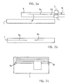
- Figure 2 is a schematic, more detailed view of the formation of a reinforcing steel.
- Figure 1 shows a reinforcing equipment comprising reels 1a to 1f for reinforcing steels. Concrete reinforcing steels of different thicknesses are wound on the reels, and so a reinforcing steel of required thickness can be selected for use.
- the term reinforcing steel refers to profiled, wire-like steel which may be smooth, profiled or deformed in cross-section and which is used in a well-known manner for reinforcing concrete products.
- the equipment further comprises transporting means 2, 3 and 4 positioned one after another.
- Reinforcing steel from one of the reels 1a to 1f is passed through a straightening apparatus 5, whereafter it extends in parallel with the direction of travel of the transporting means 2 to 4 of the welding apparatus. It is then cut into portions in such a way that the portions to be positioned in line with each other on both sides of an opening to be formed in the reinforcement are positioned in a corresponding order one after another.
- the reinforcing steel or its portions are displaced from a displacing means 6 provided in connection with the cutting apparatus to a displacing means 7 for longitudinal reinforcement elements, in which they are set out with the same mutual spacings as those between the reinforcing steels in the finished product, and then they are displaced by means of a displacing means 8 to the right position of the longitudinal reinforcing steels 9 on the transporting means 2.
- a displacing means 8 to the right position of the longitudinal reinforcing steels 9 on the transporting means 2.
- the first transverse reinforcing steel is positioned at the forward end of the longitudinal reinforcing steels 9, and similarly as the longitudinal reinforcing steels, the transverse reinforcing steel is straightened in the straightening apparatus 5 and cut into predetermined dimensions onto the displacing means 6 of the cutting apparatus, and it usually extends over the entire width of the reinforcement.
- the transverse reinforcing steels are then displaced onto a displacing means 10, whereon they are positioned in the longitudinal direction of the reinforcement with mutual spacings corresponding to their final positions. Thereafter all reinforcing steel portions to be positioned in line with each other are displaced upon the longitudinal reinforcing steels 9 by turning with a turning apparatus 11 and are welded to them by means of a welding apparatus 12.
- the reinforcement is displaced onwards by means of the transport means 3 in such a way that the following transverse reinforcing steel 13 or all reinforcing steel portions to be positioned in line with each other are welded at the right position.
- the reinforcement can be designed optimally by using mainly a reinforcing steel of a predetermined thickness, while a thicker reinforcing steel can be used within the areas of the edges of openings to increase the strength of the structure, if required. Accordingly, the entire reinforcement need not be dimensioned in accordance with the greatest load, but it can be adjusted according to the load at each point.
- the reinforcement is gradually displaced onto the displacing or transporting means 4 until it is completed, and then a reinforcement with openings or the like is displaced by means of a displacing means 15 into a pile 14 of reinforcements of different sizes, and a conventional reinforcement is displaced into a pile 16 of reinforcements by means of a displacing means 17.
- FIGs 2a to 2c show schematically the formation of reinforcing steel portions to be positioned at a certain point in the concrete reinforcement.
- a reinforcing steel 18 is passed from the right to the displacing means 6 of the cutting apparatus, whereby it is cut into reinforcing steel portions 9a and 9b of predetermined dimensions by means of the cutting apparatus 5 in accordance with the openings to be made in the concrete element.
- the reinforcing steel portions in this specific case, the portions 9a and 9b of the longitudinal reinforcing steel 9, are displaced onto the displacing means 7 shown in Figure 2a in such a way that a distance corresponding to the opening to be made in the concrete element remains between the portions, as shown in Figure 2b.
- the portions 9a and 9b are gripped by means of the displacing means 8 and they are displaced simultaneously onto a support surface formed by the transport means 2, and so there will be no reinforcing steels in the area of the openings of the concrete element, indicated by a rectangle drawn by broken lines in Figure 2c.
- the reinforcing steels or reinforcing steel portions are formed similarly for each particular area of the reinforcement, and all the reinforcing steel portions 9a and 9b are displaced simultaneously so that they are positioned appropriately. In this way, the formation of reinforcements is simple and easy even for concrete elements containing such complicated openings as shown in Figure 1 on the transporting means 2.
- transverse reinforcing steels are also formed and cut and displaced in position similarly as shown in Figures 2a-2c, that is, reinforcing steel portions to be positioned in line with each other are displaced simultaneously in position with proper lengths and spacings, whereby the openings required by the elements are formed also in the transverse direction.
- longitudinal and transverse reinforcing steels can be provided for longitudinal and transverse reinforcing steels, in which case it is possible to position the longitudinal and transverse reinforcing steels simultaneously, which speeds up the production.
- the longitudinal and transverse directions refer to the directions in the production process described, and they are not restricted to the directions of the reinforcing steels in the concrete element. Accordingly, the longitudinal reinforcing steels may be transversely positioned in the finished element or vertically positioned in a wall element, and correspondingly, the transverse reinforcing steels may extend in the longitudinal direction in the finished element.
Abstract
Description
- The invention relates to a method of automatically producing reinforcements for concrete elements, in which method a reinforcing steel needed for the production of the reinforcement is fed from a reel and straightened, whereafter the straightened reinforcing steel is cut into desired lengths, longitudinal reinforcing steels for the reinforcement are positioned side by side and reinforcing steels transverse to the longitudinal reinforcing steels are displaced one at a time upon the longitudinal reinforcing steels and the longitudinal and transverse reinforcing steels are welded together at the intersections after each displacement of a transverse reinforcing steel.
- The invention is also concerned with an equipment for automatically producing reinforcements for concrete elements, comprising at least one reel for reinforcing steel, straightening and cutting means for straightening the reinforcing steel fed from one of the reels and for cutting the straightened reinforcing steel into desired lengths, and means for positioning reinforcing steels both longitudinally and transversely of the reinforcement, and welding means for welding together the longitudinal and transverse reinforcing steels at their intersections.
- The production of concrete elements is automated and mechanized to a great extent, whereas the production of reinforcements is still largely carried out manually with little automation or mechanization. For automatic production of reinforcements, various equipments have been constructed which form a continuous mesh so that the finished reinforcement is a mesh-like product. Such an reinforcement is known e.g. from US Patent 3,405,743, in which reinforcing steels extending longitudinally of the reinforcement are positioned in a retainer provided with grooves and transverse reinforcing steels are then welded to the longitudinal reinforcing steels one at a time, and so a mesh-like rectangular reinforcement is obtained. Furthermore, SE Published Specification 344417 discloses an equipment in which the longitudinal reinforcing steels of the reinforcement are fed from reels through straightening means all side by side, and one transverse reinforcing steel at a time is similarly fed from a reel through the straightening means upon the longitudinal reinforcing steels and welded to the longitudinal reinforcing steels, and then the longitudinal reinforcing steels are moved onwards and a new transverse reinforcing steel is fed upon them.
- The known equipments described above have the drawback that the reinforcement is throughout in the form of a mesh, and so the reinforcement in the area of the openings of the concrete element always has to be cut off separately. A concrete element often comprises various window and door openings and openings for ventilation, electricity, and so on. These openings are left empty in connection with the casting of the element, and reinforcement within such areas hampers the construction and use of casting moulds. In addition to extra work, this involves a waste of material and time. In addition, the strength of the reinforcements and the reinforcing steel thicknesses always have to be dimensioned according to the maximum values, whereby thick reinforcements are used even in cases where a thinner reinforcement would be sufficient in view of the strength requirements. In the above-mentioned US Patent, the reinforcements have to be brought to the construction site as finished rods of final dimensions, which makes the handling difficult and requires plenty of room. A problem with the equipment of the above-mentioned SE Published Specification, in turn, is that it requires as many reels as longitudinal reinforcing steels, whereby the mesh density of the reinforcement is always constant and cannot be changed as required.
- The object of the present invention is to provide a method and an equipment for automatic welding of reinforcements, which avoid the above drawbacks and provide reinforcements with openings for concrete elements of different shapes and comprising openings of different kinds. The reinforcements can be shaped suitably and may comprise, if required, reinforcing steels of different lengths and thicknesses so that a reinforcing steel of suitable thickness can be selected according to the strength requirements. The method according to the invention is characterized in that the longitudinal and transverse reinforcing steels of the reinforcement are fed one at a time, and in order to provide empty spaces for openings to be formed in the finished concrete element, the reinforcing steel is cut only into such lengths as required for the area of reinforcement outside the opening, and that all reinforcing steel portions to be positioned in line with each other are displaced in position simultaneously.
- The equipment according to the invention is characterized in that it comprises means for automatically dimensioning and cutting off reinforcing steel portions intended for a predetermined area in the reinforcement in such a way that the reinforcement is formed only outside an opening to be formed in a concrete element, and that the means for positioning the reinforcing steel portions comprise a displacing means for displacing reinforcing steel portions to be positioned in line with each other in the reinforcement simultaneously to the right position.
- The basic idea of embodiments of the invention is that reinforcing steel to be positioned at a certain point or on a certain line is cut into portions such that empty spaces are left within the area of the openings of the concrete element, whereby the reinforcing steel portions to be positioned in line with each other are displaced after cutting simultaneously to their right position, and so an opening of a predetermined shape in both the longitudinal and transverse direction is formed at a desired point in the reinforcement. In this way, the reinforcement can be produced automatically without any extra cutting step.
- Certain embodiments of the invention will now be described, by way of example only with reference to the accompanying drawings in which Figure 1 illustrates schematically an equipment; and
- Figure 2 is a schematic, more detailed view of the formation of a reinforcing steel.
- Figure 1 shows a reinforcing
equipment comprising reels 1a to 1f for reinforcing steels. Concrete reinforcing steels of different thicknesses are wound on the reels, and so a reinforcing steel of required thickness can be selected for use. As used in the specification and claims of this patent application, the term reinforcing steel refers to profiled, wire-like steel which may be smooth, profiled or deformed in cross-section and which is used in a well-known manner for reinforcing concrete products. The equipment further comprises transporting means 2, 3 and 4 positioned one after another. Reinforcing steel from one of thereels 1a to 1f is passed through astraightening apparatus 5, whereafter it extends in parallel with the direction of travel of the transporting means 2 to 4 of the welding apparatus. It is then cut into portions in such a way that the portions to be positioned in line with each other on both sides of an opening to be formed in the reinforcement are positioned in a corresponding order one after another. Thereafter the reinforcing steel or its portions are displaced from adisplacing means 6 provided in connection with the cutting apparatus to adisplacing means 7 for longitudinal reinforcement elements, in which they are set out with the same mutual spacings as those between the reinforcing steels in the finished product, and then they are displaced by means of a displacing means 8 to the right position of the longitudinal reinforcingsteels 9 on the transportingmeans 2. After all the longitudinal reinforcingsteels 9 have been positioned in place, they are displaced by means of thetransporting means means 3, whereafter the positioning of transverse reinforcing steels is started. The first transverse reinforcing steel is positioned at the forward end of the longitudinal reinforcingsteels 9, and similarly as the longitudinal reinforcing steels, the transverse reinforcing steel is straightened in the straighteningapparatus 5 and cut into predetermined dimensions onto the displacing means 6 of the cutting apparatus, and it usually extends over the entire width of the reinforcement. The transverse reinforcing steels are then displaced onto adisplacing means 10, whereon they are positioned in the longitudinal direction of the reinforcement with mutual spacings corresponding to their final positions. Thereafter all reinforcing steel portions to be positioned in line with each other are displaced upon the longitudinal reinforcingsteels 9 by turning with a turningapparatus 11 and are welded to them by means of awelding apparatus 12. After the transverse reinforcingsteels 13 and the longitudinal reinforcingsteels 9 have been welded together at the intersections, the reinforcement is displaced onwards by means of the transport means 3 in such a way that the following transverse reinforcingsteel 13 or all reinforcing steel portions to be positioned in line with each other are welded at the right position. In this way, the reinforcement can be designed optimally by using mainly a reinforcing steel of a predetermined thickness, while a thicker reinforcing steel can be used within the areas of the edges of openings to increase the strength of the structure, if required. Accordingly, the entire reinforcement need not be dimensioned in accordance with the greatest load, but it can be adjusted according to the load at each point. The reinforcement is gradually displaced onto the displacing or transporting means 4 until it is completed, and then a reinforcement with openings or the like is displaced by means of a displacing means 15 into apile 14 of reinforcements of different sizes, and a conventional reinforcement is displaced into apile 16 of reinforcements by means of adisplacing means 17. - Figures 2a to 2c show schematically the formation of reinforcing steel portions to be positioned at a certain point in the concrete reinforcement. In Figure 2a, a reinforcing
steel 18 is passed from the right to the displacing means 6 of the cutting apparatus, whereby it is cut into reinforcingsteel portions cutting apparatus 5 in accordance with the openings to be made in the concrete element. Thereafter the reinforcing steel portions, in this specific case, theportions steel 9, are displaced onto thedisplacing means 7 shown in Figure 2a in such a way that a distance corresponding to the opening to be made in the concrete element remains between the portions, as shown in Figure 2b. Thereafter theportions transport means 2, and so there will be no reinforcing steels in the area of the openings of the concrete element, indicated by a rectangle drawn by broken lines in Figure 2c. The reinforcing steels or reinforcing steel portions are formed similarly for each particular area of the reinforcement, and all the reinforcingsteel portions transporting means 2. The transverse reinforcing steels are also formed and cut and displaced in position similarly as shown in Figures 2a-2c, that is, reinforcing steel portions to be positioned in line with each other are displaced simultaneously in position with proper lengths and spacings, whereby the openings required by the elements are formed also in the transverse direction. - An embodiment of the invention has been described an shown in the above description and the attached drawings by way of example, and it is in no way restricted to this example. The structure and operation of the displacing mechanism and the displacing means of the cutting apparatus may vary, provided that the reinforcing steels can be positioned appropriately with the right mutual spacings before they are displaced in position. In place of the turning displacing means shown in Figure 1, the transverse reinforcing steels can be displaced in position and shaped by means of a displacing means in which the reinforcing steel is transversely positioned and is cut into suitable dimensions and positioned appropriately. The choice of the thickness of the reinforcing steels at different points of the reinforcement and in accordance with the strength requirements of the reinforcement can be made in may different ways. Furthermore, separate straightening and displacing means can be provided for longitudinal and transverse reinforcing steels, in which case it is possible to position the longitudinal and transverse reinforcing steels simultaneously, which speeds up the production. As used in the specification and claims of this patent application, the longitudinal and transverse directions refer to the directions in the production process described, and they are not restricted to the directions of the reinforcing steels in the concrete element. Accordingly, the longitudinal reinforcing steels may be transversely positioned in the finished element or vertically positioned in a wall element, and correspondingly, the transverse reinforcing steels may extend in the longitudinal direction in the finished element.
Claims (6)
- A method of automatically producing reinforcements for concrete elements, in which method a reinforcing steel (18) needed for the production of the reinforcement is fed from a reel (1a to 1f) and straightened, whereafter the straightened reinforcing steel (18) is cut into desired lengths, longitudinal reinforcing steels (9) for the reinforcement are positioned side by side and reinforcing steels (13) transverse to the longitudinal reinforcing steels are displaced one at a time upon the longitudinal reinforcing steels and the longitudinal and transverse reinforcing steels (9, 13) are welded together at the intersections after each displacement of a transverse reinforcing steel (13), characterized in that the longitudinal and transverse reinforcing steels (9) of the reinforcement are fed one at a time, and in order to provide empty spaces for openings to be formed in the finished concrete element, the reinforcing steel (18) is cut only into such lengths as required for the area of reinforcement outside the opening, and that all reinforcing steel portions (9a, 9b) to be positioned in line with each other are displaced in position simultaneously.
- A method according to claim 1, characterized in that the longitudinal and transverse reinforcing steels (9, 13) of the reinforcement are fed from the same reinforcing steel reels (1a to 1f).
- A method according to claim 2, characterized in that the reinforcing steel is straightened so that it extends in parallel with the direction of the displacing movement of transporting means (2, 3), that the longitudinal reinforcing steels (9) are displaced in a direction transverse to the direction of the displacing movement of the transporting means to the right position, and that the transverse reinforcing steels (13) are displaced in position by turning them from said direction about a vertical axis transversely upon the longitudinal reinforcing steels.
- An equipment for automatically producing reinforcements for concrete elements, comprising at least one reel (1a to 1f) for reinforcing steel (18), straightening and cutting means (5) for straightening the reinforcing steel (18) fed from one of the reels (1a to 1f) and for cutting the straightened reinforcing steel (18) into desired lengths, and means (6 to 8, 10, 11) for positioning reinforcing steels (9, 13) both longitudinally and transversely of the reinforcement, and welding means (12) for welding together the longitudinal and transverse reinforcing steels (9, 13) at their intersections, characterized in that it comprises means for automatically dimensioning and cutting off reinforcing steel portions (9a, 9b) intended for a predetermined area in the reinforcement in such a way that the reinforcement is formed only outside an opening to be formed in a concrete element, and that the means for positioning the reinforcing steel portions (9a, 9b) comprise a displacing means (8) for displacing reinforcing steel portions (9a, 9b) to be positioned in line with each other in the reinforcement simultaneously to the right position.
- An equipment according to claim 4, characterized in that it comprises several reels (1a to 1f) each for a reinforcing steels (18) of different thickness, whereby a reinforcing steel (18) of desired thickness can be selected and fed to the straightening and cutting means (5).
- An equipment according to claim 4 or 5, characterized in that both the longitudinal and the transverse reinforcing steels (9, 13) are fed from the same reels (1a to 1f) through the same straightening and cutting means (5) so that they extend in parallel with the direction of travel of the transporting means (2, 3) of the equipment, that the means for positioning the reinforcing steels (9, 13) comprise a displacing means (11) mounted turnably about a vertical axis for turning the transverse reinforcing steel portions (13) upon the longitudinal reinforcing steels (9).
Applications Claiming Priority (2)
| Application Number | Priority Date | Filing Date | Title |
|---|---|---|---|
| FI905267A FI85957C (en) | 1990-10-25 | 1990-10-25 | Method and apparatus for the automatic manufacture of reinforcements for concrete elements |
| FI905267 | 1990-10-25 |
Publications (2)
| Publication Number | Publication Date |
|---|---|
| EP0482842A1 true EP0482842A1 (en) | 1992-04-29 |
| EP0482842B1 EP0482842B1 (en) | 1996-01-10 |
Family
ID=8531310
Family Applications (1)
| Application Number | Title | Priority Date | Filing Date |
|---|---|---|---|
| EP91309653A Expired - Lifetime EP0482842B1 (en) | 1990-10-25 | 1991-10-18 | Method and equipment for automatic production of reinforcing steels for concrete elements |
Country Status (4)
| Country | Link |
|---|---|
| EP (1) | EP0482842B1 (en) |
| AT (1) | ATE132779T1 (en) |
| DE (1) | DE69116304T2 (en) |
| FI (1) | FI85957C (en) |
Cited By (11)
| Publication number | Priority date | Publication date | Assignee | Title |
|---|---|---|---|---|
| WO1995006532A1 (en) * | 1993-08-30 | 1995-03-09 | Claudio Bernardinis | Automatic bar feeding device |
| FR2731247A1 (en) * | 1995-03-03 | 1996-09-06 | Primot Gilles | METHOD OF ASSEMBLING REINFORCEMENTS FOR CONCRETE PRODUCTS AND INSTALLATION SUITABLE FOR IMPLEMENTING IT |
| EP0733416A1 (en) * | 1995-03-24 | 1996-09-25 | Filzmoser, Franz | Method and device for the manufacture of reinforcing grids |
| EP0951955A2 (en) * | 1998-04-21 | 1999-10-27 | Rainer Knecht | Method and device for the manufacture of reinforcements |
| ITUD20100173A1 (en) * | 2010-09-27 | 2012-03-28 | Awm Spa | "METHOD OF POWER SUPPLY AND RELATIVE TRANSVERSAL POWER SUPPLY OF WHOLE BARS OR STEEL ROUNDS FOR AUTOMATIC FORMATION OF ELECTRO-WELDED METALLIC NETS WITH SPECIAL SHAPED SHAPES". |
| ITBO20100758A1 (en) * | 2010-12-23 | 2012-06-24 | Schnell Spa | METHOD AND EQUIPMENT FOR REALIZING REINFORCED CONCRETE REINFORCEMENTS |
| EP2740559A1 (en) | 2012-12-06 | 2014-06-11 | A.W.M. S.p.A. | Automatic machine for the production of electro-welded meshes |
| CN108405767A (en) * | 2018-07-12 | 2018-08-17 | 湖南三快而居住宅工业有限公司 | Reinforced mesh welding production line |
| EP3715009A1 (en) * | 2019-03-28 | 2020-09-30 | apilion Machines + Services GmbH | Mat welding system for producing reinforcement mats |
| WO2021209304A1 (en) * | 2020-04-15 | 2021-10-21 | Progress Maschinen & Automation Ag | Mat welding system for producing concrete steel mats and method using same |
| AT524506A1 (en) * | 2020-11-25 | 2022-06-15 | Progress Maschinen & Automation Ag | Method for calculating production parameters of at least one reinforcement |
Citations (3)
| Publication number | Priority date | Publication date | Assignee | Title |
|---|---|---|---|---|
| FR1215087A (en) * | 1958-11-05 | 1960-04-13 | Method of establishing reinforcements for reinforced concrete slabs | |
| US3405743A (en) * | 1965-09-29 | 1968-10-15 | Northwestern Steel & Wire Co | Reinforcing mat fabricating apparatus |
| EP0125716A1 (en) * | 1983-05-03 | 1984-11-21 | Pierre Decoux | Method and device for feeding the cross wires to machines for welding metal wire grates |
-
1990
- 1990-10-25 FI FI905267A patent/FI85957C/en not_active IP Right Cessation
-
1991
- 1991-10-18 DE DE69116304T patent/DE69116304T2/en not_active Expired - Fee Related
- 1991-10-18 EP EP91309653A patent/EP0482842B1/en not_active Expired - Lifetime
- 1991-10-18 AT AT91309653T patent/ATE132779T1/en active
Patent Citations (3)
| Publication number | Priority date | Publication date | Assignee | Title |
|---|---|---|---|---|
| FR1215087A (en) * | 1958-11-05 | 1960-04-13 | Method of establishing reinforcements for reinforced concrete slabs | |
| US3405743A (en) * | 1965-09-29 | 1968-10-15 | Northwestern Steel & Wire Co | Reinforcing mat fabricating apparatus |
| EP0125716A1 (en) * | 1983-05-03 | 1984-11-21 | Pierre Decoux | Method and device for feeding the cross wires to machines for welding metal wire grates |
Non-Patent Citations (1)
| Title |
|---|
| WELDING AND METAL FABRICATION vol. 49, no. 2, March 1981, SUSSEX GB pages 77 - 79; D. A. BOWMAN: 'MESH WELDING AT HIGH RATES AND TO NON-STANDARD PATTERNS' * |
Cited By (15)
| Publication number | Priority date | Publication date | Assignee | Title |
|---|---|---|---|---|
| WO1995006532A1 (en) * | 1993-08-30 | 1995-03-09 | Claudio Bernardinis | Automatic bar feeding device |
| FR2731247A1 (en) * | 1995-03-03 | 1996-09-06 | Primot Gilles | METHOD OF ASSEMBLING REINFORCEMENTS FOR CONCRETE PRODUCTS AND INSTALLATION SUITABLE FOR IMPLEMENTING IT |
| WO1996027462A1 (en) * | 1995-03-03 | 1996-09-12 | Gilles Primot | Method for assembling reinforcements for concrete elements, and apparatus therefor |
| EP0733416A1 (en) * | 1995-03-24 | 1996-09-25 | Filzmoser, Franz | Method and device for the manufacture of reinforcing grids |
| EP0951955A2 (en) * | 1998-04-21 | 1999-10-27 | Rainer Knecht | Method and device for the manufacture of reinforcements |
| EP0951955A3 (en) * | 1998-04-21 | 2001-01-24 | Rainer Knecht | Method and device for the manufacture of reinforcements |
| ITUD20100173A1 (en) * | 2010-09-27 | 2012-03-28 | Awm Spa | "METHOD OF POWER SUPPLY AND RELATIVE TRANSVERSAL POWER SUPPLY OF WHOLE BARS OR STEEL ROUNDS FOR AUTOMATIC FORMATION OF ELECTRO-WELDED METALLIC NETS WITH SPECIAL SHAPED SHAPES". |
| EP2433724A1 (en) * | 2010-09-27 | 2012-03-28 | A.W.M. s.p.a. | Feeding system and relevant transversal feeder for entire bars or steel bars suitable for automatic plants producing electric welding wire netting with particular shapes |
| ITBO20100758A1 (en) * | 2010-12-23 | 2012-06-24 | Schnell Spa | METHOD AND EQUIPMENT FOR REALIZING REINFORCED CONCRETE REINFORCEMENTS |
| EP2740559A1 (en) | 2012-12-06 | 2014-06-11 | A.W.M. S.p.A. | Automatic machine for the production of electro-welded meshes |
| CN108405767A (en) * | 2018-07-12 | 2018-08-17 | 湖南三快而居住宅工业有限公司 | Reinforced mesh welding production line |
| EP3715009A1 (en) * | 2019-03-28 | 2020-09-30 | apilion Machines + Services GmbH | Mat welding system for producing reinforcement mats |
| WO2021209304A1 (en) * | 2020-04-15 | 2021-10-21 | Progress Maschinen & Automation Ag | Mat welding system for producing concrete steel mats and method using same |
| AT524506A1 (en) * | 2020-11-25 | 2022-06-15 | Progress Maschinen & Automation Ag | Method for calculating production parameters of at least one reinforcement |
| AT17865U1 (en) * | 2020-11-25 | 2023-05-15 | Progress Maschinen & Automation Ag | Method for calculating production parameters of at least one reinforcement |
Also Published As
| Publication number | Publication date |
|---|---|
| DE69116304D1 (en) | 1996-02-22 |
| DE69116304T2 (en) | 1996-06-27 |
| EP0482842B1 (en) | 1996-01-10 |
| FI85957C (en) | 1992-06-25 |
| FI85957B (en) | 1992-03-13 |
| FI905267A (en) | 1992-03-13 |
| ATE132779T1 (en) | 1996-01-15 |
| FI905267A0 (en) | 1990-10-25 |
Similar Documents
| Publication | Publication Date | Title |
|---|---|---|
| EP0482842B1 (en) | Method and equipment for automatic production of reinforcing steels for concrete elements | |
| EP0507054B1 (en) | Shuttering element | |
| DE602004007051T2 (en) | Straight beam for use in curved suspended ceilings and method of making the same | |
| DE3201918C1 (en) | Device for storing reinforcement steel and method for its production and device for carrying out the method | |
| DE2613579C2 (en) | Method for producing a flat or three-dimensional reinforcement structure from parallel longitudinal reinforcing bars and transverse reinforcing bars arranged transversely to them | |
| EP2255938A2 (en) | Automatic cutting assembly of a casting station | |
| EP0733416B1 (en) | Method and device for the manufacture of reinforcing grids | |
| DE2316874C2 (en) | Spacer for supporting the reinforcement in concrete components and method for producing the spacer | |
| DE3932810C2 (en) | Device for inserting reinforcement into a pallet with compartment division | |
| EP2246499B1 (en) | Reinforcement element | |
| EP1132545B1 (en) | Shuttering material | |
| JPH10113735A (en) | Device for producing corrugated reinforcing mat | |
| EP0804658B1 (en) | Concrete steel mesh for large-surface reinforced concrete buildings | |
| EP0355776A2 (en) | Method for reinforcing of concrete slabs, device for carrying out the method as well as lattice girders | |
| EP0860218B1 (en) | Method and device for producing continuous spirals with closed polygon forms from wire, concrete steel or metal tube | |
| EP3687928B1 (en) | Method for spatially arranging coils in a coil store and combination of a processing machine and a coil store | |
| JP2005188064A (en) | Automatic binding equipment for reinforcement grating | |
| EP0394815B1 (en) | Steel reinforcing cage | |
| EP4135916A1 (en) | Mat welding system for producing concrete steel mats and method using same | |
| DE2658622A1 (en) | Concrete bonding formwork element - is formed of sprayed fibre concrete with fibres protruding on rear side | |
| JPH07217072A (en) | Reinforcing bar and manufacture thereof | |
| DE10037193C2 (en) | formwork | |
| EP0789116B1 (en) | Shuttering element | |
| DE102013018907A1 (en) | Apparatus and method for producing reinforcing mats and reinforcing mat | |
| EP0541880B1 (en) | Spacer means for bottom reinforcement |
Legal Events
| Date | Code | Title | Description |
|---|---|---|---|
| PUAI | Public reference made under article 153(3) epc to a published international application that has entered the european phase |
Free format text: ORIGINAL CODE: 0009012 |
|
| AK | Designated contracting states |
Kind code of ref document: A1 Designated state(s): AT BE CH DE DK FR GB IT LI NL SE |
|
| 17P | Request for examination filed |
Effective date: 19920908 |
|
| 17Q | First examination report despatched |
Effective date: 19940223 |
|
| GRAA | (expected) grant |
Free format text: ORIGINAL CODE: 0009210 |
|
| RAP1 | Party data changed (applicant data changed or rights of an application transferred) |
Owner name: PARTEK CONCRETE ENGINEERING OY AB |
|
| AK | Designated contracting states |
Kind code of ref document: B1 Designated state(s): AT BE CH DE DK FR GB IT LI NL SE |
|
| PG25 | Lapsed in a contracting state [announced via postgrant information from national office to epo] |
Ref country code: IT Free format text: LAPSE BECAUSE OF FAILURE TO SUBMIT A TRANSLATION OF THE DESCRIPTION OR TO PAY THE FEE WITHIN THE PRESCRIBED TIME-LIMIT;WARNING: LAPSES OF ITALIAN PATENTS WITH EFFECTIVE DATE BEFORE 2007 MAY HAVE OCCURRED AT ANY TIME BEFORE 2007. THE CORRECT EFFECTIVE DATE MAY BE DIFFERENT FROM THE ONE RECORDED. Effective date: 19960110 Ref country code: FR Effective date: 19960110 Ref country code: BE Effective date: 19960110 Ref country code: LI Effective date: 19960110 Ref country code: DK Effective date: 19960110 Ref country code: AT Effective date: 19960110 Ref country code: CH Effective date: 19960110 |
|
| REF | Corresponds to: |
Ref document number: 132779 Country of ref document: AT Date of ref document: 19960115 Kind code of ref document: T |
|
| REF | Corresponds to: |
Ref document number: 69116304 Country of ref document: DE Date of ref document: 19960222 |
|
| PG25 | Lapsed in a contracting state [announced via postgrant information from national office to epo] |
Ref country code: SE Effective date: 19960410 |
|
| EN | Fr: translation not filed | ||
| REG | Reference to a national code |
Ref country code: CH Ref legal event code: PL |
|
| PG25 | Lapsed in a contracting state [announced via postgrant information from national office to epo] |
Ref country code: GB Effective date: 19961018 |
|
| PLBE | No opposition filed within time limit |
Free format text: ORIGINAL CODE: 0009261 |
|
| STAA | Information on the status of an ep patent application or granted ep patent |
Free format text: STATUS: NO OPPOSITION FILED WITHIN TIME LIMIT |
|
| 26N | No opposition filed | ||
| GBPC | Gb: european patent ceased through non-payment of renewal fee |
Effective date: 19961018 |
|
| PGFP | Annual fee paid to national office [announced via postgrant information from national office to epo] |
Ref country code: NL Payment date: 19981015 Year of fee payment: 8 |
|
| PGFP | Annual fee paid to national office [announced via postgrant information from national office to epo] |
Ref country code: DE Payment date: 19981016 Year of fee payment: 8 |
|
| PG25 | Lapsed in a contracting state [announced via postgrant information from national office to epo] |
Ref country code: NL Free format text: LAPSE BECAUSE OF NON-PAYMENT OF DUE FEES Effective date: 20000501 |
|
| NLV4 | Nl: lapsed or anulled due to non-payment of the annual fee |
Effective date: 20000501 |
|
| PG25 | Lapsed in a contracting state [announced via postgrant information from national office to epo] |
Ref country code: DE Free format text: LAPSE BECAUSE OF NON-PAYMENT OF DUE FEES Effective date: 20000801 |