EP0467071A2 - Calling device for telecommunication terminals - Google Patents
Calling device for telecommunication terminals Download PDFInfo
- Publication number
- EP0467071A2 EP0467071A2 EP91109668A EP91109668A EP0467071A2 EP 0467071 A2 EP0467071 A2 EP 0467071A2 EP 91109668 A EP91109668 A EP 91109668A EP 91109668 A EP91109668 A EP 91109668A EP 0467071 A2 EP0467071 A2 EP 0467071A2
- Authority
- EP
- European Patent Office
- Prior art keywords
- call
- organ
- signal
- communication terminal
- user
- Prior art date
- Legal status (The legal status is an assumption and is not a legal conclusion. Google has not performed a legal analysis and makes no representation as to the accuracy of the status listed.)
- Withdrawn
Links
Images


Classifications
-
- G—PHYSICS
- G08—SIGNALLING
- G08B—SIGNALLING OR CALLING SYSTEMS; ORDER TELEGRAPHS; ALARM SYSTEMS
- G08B3/00—Audible signalling systems; Audible personal calling systems
- G08B3/10—Audible signalling systems; Audible personal calling systems using electric transmission; using electromagnetic transmission
-
- G—PHYSICS
- G08—SIGNALLING
- G08B—SIGNALLING OR CALLING SYSTEMS; ORDER TELEGRAPHS; ALARM SYSTEMS
- G08B6/00—Tactile signalling systems, e.g. personal calling systems
-
- H—ELECTRICITY
- H04—ELECTRIC COMMUNICATION TECHNIQUE
- H04M—TELEPHONIC COMMUNICATION
- H04M19/00—Current supply arrangements for telephone systems
- H04M19/02—Current supply arrangements for telephone systems providing ringing current or supervisory tones, e.g. dialling tone or busy tone
- H04M19/04—Current supply arrangements for telephone systems providing ringing current or supervisory tones, e.g. dialling tone or busy tone the ringing-current being generated at the substations
- H04M19/047—Vibrating means for incoming calls
Definitions
- the invention relates to a call organ for telecommunications terminals according to the preamble of claim 1.
- a cordless telephone is known.
- a call is received by the fixed part of the telephone set and converted into a digital ringing telegram which is emitted by the antenna.
- This signal is received in the movable part of the telephone set and sent via a line to a control unit which actuates an alarm clock.
- This is an acoustic call signal, which is of course not only perceptible to the user.
- the call signals are always perceptible by all those who are in the vicinity of the telephone set in question.
- Such call signals can be perceived as annoying when cordless telephones or pagers are used by people who always want to be reachable for a call and are, for example, in meetings or conferences. If calls arrive in such situations, this can, for example, disrupt a lecture.
- the object of the invention is to present a call organ, whereby a call criterion is formed, which discreetly notifies a person to be called of an existing call that uninvolved persons cannot become aware of it.
- the portable communication terminal with this call organ or the call organ as a single device should be so small and handy that it can be worn on the user's body.
- the call signal AS is fed to a multivibrator MV.
- Current vibrations are thus generated, which are supplied to a magnetic coil MS.
- There is an oscillating armature SA in the magnet coil which is set in vibration by the magnetic field that arises.
- the frequency of these vibrations of the oscillating armature SA and the other design of the call organ ensures that only vibrations are perceptible but no audible noises are produced.
- the call organ AO is installed in the communication terminal KE, as shown in FIG. 2, it is connected to the power supply located there. However, space is also provided in the call organ AO for its own power supply, which must be installed when the call organ AO is operated wirelessly outside of a communication terminal KE.
- a switch S is arranged, which can preferably be a mobile telephone.
- the acoustic call organs located in the communication terminal are deactivated.
- the call signal AS is then passed directly to the call organ AO, which generates an inaudible call criterion in the form of vibrations. If a communication terminal KE designed in this way is worn in the clothing of a user, then call signals are clearly perceptible without disturbing uninvolved persons.
- the call organ AO shown in FIG. 3 is an independently operating device which can receive the call signals transmitted wirelessly from a transmitter US located on the communication terminal KE.
- an ultrasound transmission link is provided for this.
- the call signal is thus implemented in the communication terminal KE and sent to an ultrasound transmitter US. This sends out the call signal provided with an individual coding, so that it can be received by the ultrasound receiver UE of the call organ AO.
- it can also be a stationary communication terminal KE, which must then be located in the same room.
- a switch S is provided on the communication terminal KE, whereby the acoustic call organ is switched off. At the same time, activation of the wireless transmission link is initiated by actuating the switch S.
- FIG. 4 shows how a call organ AO can be connected to a communication terminal KE via a connecting cable VK. Only a contact socket KB must then be provided on the communication terminal KE. When inserting the plug for the connecting cable VK, a contact is then actuated, which switches off the acoustic call organ. In this version, the call signal AS is transmitted via the connecting cable VK and the power supply is supplied, so that no separate battery is required in the call organ AO.
Abstract
Description
Die Erfindung betrifft ein Anruforgan für Telekommunikations-Endgeräte nach dem Oberbegriff des Patentanspruchs 1.The invention relates to a call organ for telecommunications terminals according to the preamble of
Aus der DE-OS 19 39 385, wo eine Schaltungsanordnung für Fernsprechteilnehmerstellen beschrieben wird, ist es bekannt, vom akustischen Anrufsignal ein zusätzliches optisches Anrufsignal zu gewinnen. Zum Einschalten einer Lampe, welche den Telefonapparat im Anrufzustand beleuchten soll, ist ein Relais vorgesehen. Dieses Relais wird durch eine mechanische oder elektrische Kopplung mit dem Anrufkreis des Fernsprechapparates betätigt. Mit dem Einschalten eines optischen Anrufsignals soll in einem verdunkelten Raum das Auffinden eines Fernsprechgerätes erleichtert werden. Außerdem soll insbesondere bei Nachtanrufen erreicht werden, daß nur derjenige aufgeweckt wird, in dessen Nähe sich die Fernsprechteilnehmerstation befindet. Sind jedoch mehrere Personen in einem Raum, so kann nicht erwartet werden, daß nur eine Person auf den Anruf aufmerksam wird. Bei einem derartigen Konzept werden also auch die Personen von einem Anruf gestört, für die der Anruf nicht bestimmt ist.From DE-OS 19 39 385, where a circuit arrangement for telephone subscriber stations is described, it is known to obtain an additional optical call signal from the acoustic call signal. A relay is provided for switching on a lamp which is intended to illuminate the telephone set in the call state. This relay is actuated by mechanical or electrical coupling with the call circuit of the telephone set. By turning on an optical call signal, finding a telephone in a darkened room should be made easier. In addition, especially in the case of night calls, the aim is to only wake up the person in the vicinity of which the subscriber station is located. However, if there are several people in a room, it cannot be expected that only one person will notice the call. With such a concept, the people who are not intended for the call are also disturbed by a call.
Aus der DE-OS 32 36 194 ist ein schnurloser Fernsprechapparat bekannt. Wie im letzten Absatz auf Seite 6 beschrieben ist, wird ein Anruf von dem ortsfesten Teil des Fernsprechapparates empfangen und in ein digitales Ruftelegramm umgewandelt, welches von der Antenne abgestrahlt wird. Im beweglichen Teil des Fernsprechapparates wird dieses Signal empfangen und über eine Leitung zu einer Steuerung gegeben, welche einen Wecker betätigt. Hierbei handelt es sich also um ein akustisches Anrufsignal, welches selbstverständlich nicht nur von dem jeweiligen Benutzer wahrnehmbar ist.From DE-OS 32 36 194 a cordless telephone is known. As described in the last paragraph on page 6, a call is received by the fixed part of the telephone set and converted into a digital ringing telegram which is emitted by the antenna. This signal is received in the movable part of the telephone set and sent via a line to a control unit which actuates an alarm clock. This is an acoustic call signal, which is of course not only perceptible to the user.
Bei Fernsprechapparaten mit akustischen und/oder optischen Anruforganen sind die Anrufsignale immer von all denjenigen Personen wahrnehmbar, welche sich in der Nähe des betreffenden Fernsprechapparates befinden. Derartige Anrufsignale können als störend empfunden werden, wenn schnurlose Fernsprechapparate oder Funkrufempfänger von Personen benutzt werden, welche immer für einen Anruf erreichbar sein wollen und sich beispielsweise in Besprechungen oder Konferenzen befinden. Wenn in solchen Situationen Anrufe ankommen, so kann dies beispielsweise zur Störung eines Vortrages führen.In telephone sets with acoustic and / or optical call organs, the call signals are always perceptible by all those who are in the vicinity of the telephone set in question. Such call signals can be perceived as annoying when cordless telephones or pagers are used by people who always want to be reachable for a call and are, for example, in meetings or conferences. If calls arrive in such situations, this can, for example, disrupt a lecture.
Ausgehend vom vorgenannten Stand der Technik besteht die Aufgabe der Erfindung darin, ein Anruforgan vorzustellen, womit ein Anrufkriterium gebildet wird, das eine anzurufende Person so diskret auf einen vorliegenden Anruf hinweist, daß unbeteiligte Personen nicht aufmerksam werden können. Dabei soll das tragbare Kommunikations-Endgerät mit diesem Anruforgan oder das Anruforgan als Einzelgerät so klein und handlich sein, daß es am Körper des Benutzers getragen werden kann.Starting from the aforementioned prior art, the object of the invention is to present a call organ, whereby a call criterion is formed, which discreetly notifies a person to be called of an existing call that uninvolved persons cannot become aware of it. The portable communication terminal with this call organ or the call organ as a single device should be so small and handy that it can be worn on the user's body.
Zur Lösung dieser Aufgabe sind Merkmale vorgesehen, wie sie im Patentanspruch 1 angegeben sind.To solve this problem, features are provided as specified in
Damit wird in vorteilhafter Weise erreicht, daß ein ankommender Anruf von einem Benutzer deutlich spürbar erkannt werden kann, ohne daß dies in der unmittelbaren Umgebung wahrgenommen wird. Der Benutzer kann dann je nach Situation entscheiden, ob er zur Beantwortung des Anrufes den Raum verlassen will, um andere Personen nicht zu stören.This advantageously ensures that an incoming call can be clearly recognized by a user, without this being perceived in the immediate vicinity. Depending on the situation, the user can then decide whether he wants to leave the room to answer the call so as not to disturb other people.
Bei den in den Unteransprüchen angegebenen Weiterbildungen der Erfindung wird aufgezeigt, wie das Anruforgan beschaffen sein kann und auf welche Weise es den betrieblichen Anforderungen anpaßbar ist.In the developments of the invention specified in the subclaims, it is shown how the call organ can be made and how it can be adapted to the operational requirements.
Ein Ausführungsbeispiel der Erfindung wird nachfolgend anhand von Zeichnungen näher erläutert.An embodiment of the invention is explained below with reference to drawings.
Es zeigt
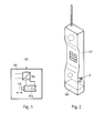
- Fig. 1: Das Blockschaltbild eines Anruforgans.
- Fig. 2: Ein Kommunikations-Endgerät mit eingebautem Anruforgan.
- Fig. 3: Ein Kommunikations-Endgerät mit externem Anruforgan und drahtloser Übertragung des Anrufsignals.
- Fig. 4: Ein Kommunikations-Endgerät mit über ein Kabel angeschlossenem Anruforgan.
- Fig. 1: The block diagram of a call organ.
- Fig. 2: A communication terminal with built-in call organ.
- Fig. 3: A communication terminal with an external call organ and wireless transmission of the call signal.
- Fig. 4: A communication terminal with a call organ connected via a cable.
Bei dem in Fig. 1 gezeigten Blockschaltbild des Anruforgans AO wird das Anrufsignal AS einem Multivibrator MV zugeführt. Damit werden Stromschwingungen erzeugt, welche einer Magnetspule MS zugeführt werden. In der Magnetspule befindet sich ein Schwinganker SA welcher durch das entstehende Magnetfeld in Vibrationen versetzt wird. Durch die Frequenz dieser Vibrationen des Schwingankers SA und die sonstige Ausführung des Anruforgans wird gewährleistet, daß nur Vibrationen wahrnehmbar sind, aber keine hörbare Geräusche entstehen. Wenn das Anruforgan AO in das Kommunikations-Endgerät KE eingebaut ist, wie dies in Fig. 2 dargestellt ist, so wird es an die dort befindliche Stromversorgung angeschlossen. In dem Anruforgan AO ist jedoch auch Raum für eine eigene Stromversorgung vorgesehen, welche dann eingebaut sein muß, wenn das Anruforgan AO außerhalb von einem Kommunikations-Endgerät KE drahtlos betrieben wird.In the block diagram of the call organ AO shown in FIG. 1, the call signal AS is fed to a multivibrator MV. Current vibrations are thus generated, which are supplied to a magnetic coil MS. There is an oscillating armature SA in the magnet coil which is set in vibration by the magnetic field that arises. The frequency of these vibrations of the oscillating armature SA and the other design of the call organ ensures that only vibrations are perceptible but no audible noises are produced. If the call organ AO is installed in the communication terminal KE, as shown in FIG. 2, it is connected to the power supply located there. However, space is also provided in the call organ AO for its own power supply, which must be installed when the call organ AO is operated wirelessly outside of a communication terminal KE.
Bei dem in Fig. 2 dargestellten Kommunikations-Endgerät sei angenommen, daß sich das Anruforgan AO im gleichen Gehäuse befindet. Es ist jedoch auch denkbar, daß das Anruforgan AO steckbar am Kommunikations-Endgerät KE befestigt ist. Am Kommunikations-Endgerät KE, wobei es sich vorzugsweise um ein Mobiltelefon handeln kann, ist ein Schalter S angeordnet. Wenn dieser Schalter S betätigt wird, werden die im Kommunikations-Endgerät befindlichen akustischen Anruforgane außer Betrieb gesetzt. Das Anrufsignal AS wird dann direkt zu dem Anruforgan AO geleitet, welches ein nicht hörbares Anrufkriterium in Form von Vibrationen erzeugt. Wenn ein derart ausgestaltetes Kommunikations-Endgerät KE in der Kleidung eines Benutzers getragen wird, so sind Anrufsignale deutlich wahrnehmbar, ohne daß unbeteiligte Personen gestört werden.In the communication terminal shown in Fig. 2 it is assumed that the call organ AO is in the same housing. However, it is also conceivable for the call organ AO to be plugged into the communication terminal KE. On the KE communication terminal, a switch S is arranged, which can preferably be a mobile telephone. When this switch S is actuated, the acoustic call organs located in the communication terminal are deactivated. The call signal AS is then passed directly to the call organ AO, which generates an inaudible call criterion in the form of vibrations. If a communication terminal KE designed in this way is worn in the clothing of a user, then call signals are clearly perceptible without disturbing uninvolved persons.
Bei dem in Fig. 3 dargestellten Anruforgan AO handelt es sich um ein unabhängig arbeitendes Gerät, welches die von einem am Kommunikations-Endgerät KE befindlichen Sender US drahtlos ausgesendeten Anrufsinale empfangen kann. Hierfür ist beispielsweise eine Ultraschall-Übertragungsstrecke vorgesehen. Das Anrufsignal wird also im Kommunikations-Endgerät KE umgesetzt und auf einen Ultraschallsender US gegeben. Dieser sendet das mit einer individuellen Codierung versehene Anrufsignal aus, so daß es vom Ultraschallempfänger UE des Anruforgans AO empfangen werden kann. Bei einer derartigen Betriebsweise genügt es, daß der Benutzer lediglich das relativ kleine Anruforgan AO bei sich trägt, ohne daß sich das Kommunikations-Endgerät KE in seiner unmittelbaren Nähe befinden muß. In diesem Fall kann es sich auch um ein ortsfestes Kommunikations-Endgerät KE handeln, welches sich dann im gleichen Raum befinden muß. Auch in diesem Betriebsfall ist ein Schalter S am Kommunikations-Endgerät KE vorgesehen, womit das akustische Anruforgan abgeschaltet wird. Gleichzeitig wird durch Betätigen des Schalters S die Aktivierung der drahtlosen Übertragungsstrecke veranlaßt.The call organ AO shown in FIG. 3 is an independently operating device which can receive the call signals transmitted wirelessly from a transmitter US located on the communication terminal KE. For example, an ultrasound transmission link is provided for this. The call signal is thus implemented in the communication terminal KE and sent to an ultrasound transmitter US. This sends out the call signal provided with an individual coding, so that it can be received by the ultrasound receiver UE of the call organ AO. In such a mode of operation, it is sufficient that the user only carries the relatively small call organ AO with him, without the communication terminal device KE having to be in its immediate vicinity. In this case, it can also be a stationary communication terminal KE, which must then be located in the same room. In this operating case too, a switch S is provided on the communication terminal KE, whereby the acoustic call organ is switched off. At the same time, activation of the wireless transmission link is initiated by actuating the switch S.
In der Fig. 4 ist dargestellt, wie ein Anruforgan AO über ein Verbindungskabel VK mit einem Kommunikations-Endgerät KE verbunden sein kann. Am Kommunikations-Endgerät KE muß dann lediglich eine Kontaktbuchse KB vorgesehen sein. Beim Einführen des Steckers für das Verbindungskabel VK wird dann ein Kontakt betätigt, welcher das akustische Anruforgan abschaltet. Bei dieser Version wird über das Verbindungskabel VK das Anrufsignal AS übertragen und die Stromversorgung zugeführt, so daß im Anruforgan AO keine eigene Batterie vorhanden sein muß.FIG. 4 shows how a call organ AO can be connected to a communication terminal KE via a connecting cable VK. Only a contact socket KB must then be provided on the communication terminal KE. When inserting the plug for the connecting cable VK, a contact is then actuated, which switches off the acoustic call organ. In this version, the call signal AS is transmitted via the connecting cable VK and the power supply is supplied, so that no separate battery is required in the call organ AO.
Claims (8)
dadurch gekennzeichnet,
daß in dem Anruforgan (AO) bei einem empfangenen Anrufsignal (AS) ein pulsierendes Kraftfeld erzeugt wird, wobei durch einen dadurch bewegten Schwinganker (SA) Vibrationen entstehen, die einem Benutzer einen Anruf signalisieren, ohne daß ein hörbares oder sichtbares Signal entsteht.1. call organ for telecommunication terminals, in particular mobile telephones and pagers, with which an electrical call signal arriving via a connecting line or wirelessly is converted into a criterion perceptible to the user, uninvolved persons not being disturbed,
characterized,
that a pulsating force field is generated in the call organ (AO) when a call signal (AS) is received, vibrations resulting from a moving armature (SA) thereby moving, which signal a user to a call without an audible or visible signal being produced.
dadurch gekennzeichnet,
daß für die Erzeugung eines elektromagnetischen Feldes eine Magnetspule (MS) vorgesehen ist.2. call organ according to claim 1,
characterized,
that a magnetic coil (MS) is provided for generating an electromagnetic field.
dadurch gekennzeichnet,
daß das Anruforgan (AO) als selbsttätig funktionsfähige Baugruppe in einem mobilen Kommunikations-Endgerät (KE) untergebracht ist und manuell durch einen dafür vorgesehenen Schalter (S) anstelle von akustischen oder optischen Anruforganen einschaltbar ist.3. call organ according to claim 1,
characterized,
that the call organ (AO) is housed as an automatically functional assembly in a mobile communication terminal (KE) and can be switched on manually by means of a switch (S) provided instead of acoustic or optical call organs.
dadurch gekennzeichnet,
daß das Anruforgan (AO) als selbsttätig funktionsfähige Baugruppe sich außerhalb eines Kommunikations-Endgerätes (KE) befindet und von diesem drahtlos Anrufsignale (AS) übermittelt bekommt, wenn dort ein dafür vorgesehener Schalter (S) betätigt ist, womit akustische oder optische Anruforgane ausgeschaltet sind.4. call organ according to claim 1,
characterized,
that the call organ (AO) as an automatically functional assembly is located outside of a communication terminal (KE) and receives wireless call signals (AS) from it when a switch (S) provided for this purpose is actuated, whereby acoustic or optical call organs are switched off .
dadurch gekennzeichnet,
daß bei der drahtlosen Übermittlung eines Anrufsignals (AS) vom Kommunikations-Endgerät (KE) zum Anruforgan (AO) eine individuelle Codierung vorgesehen ist.5. call organ according to claim 4,
characterized,
that an individual coding is provided for the wireless transmission of a call signal (AS) from the communication terminal (KE) to the call organ (AO).
dadurch gekennzeichnet,
daß das Anruforgan (AO) als selbsttätig funktionsfähige Baugruppe sich außerhalb eines Kommunikations-Endgerätes (KE) befindet und von diesem Anrufsignale (AS) über ein Verbindungskabel (VK) übermittelt bekommt, wobei akustische oder optische Anruforgane ausgeschaltet sind, wenn das Verbindungskabel (VK) gesteckt ist.6. call organ according to claim 1,
characterized,
that the call organ (AO) as an automatically functional assembly is located outside a communication terminal (KE) and receives call signals (AS) from it via a connecting cable (VK), acoustic or optical calling devices being switched off when the connecting cable (VK) is stuck.
dadurch gekennzeichnet,
daß die Frequenz der Vibrationen des Schwingankers (SA) niedriger ist als die Frequenzen hörbarer Töne.7. call organ according to claim 1,
characterized,
that the frequency of the vibrations of the vibrating armature (SA) is lower than the fre sequence audible tones.
dadurch gekennzeichnet,
daß der Rhythmus der Vibrationen des Schwingankers (SA) dem Rhythmus des Anrufsignals (AS) entspricht.8. call organ according to claim 1,
characterized,
that the rhythm of the vibrations of the oscillating armature (SA) corresponds to the rhythm of the call signal (AS).
Applications Claiming Priority (2)
| Application Number | Priority Date | Filing Date | Title |
|---|---|---|---|
| DE4022959 | 1990-07-19 | ||
| DE19904022959 DE4022959A1 (en) | 1990-07-19 | 1990-07-19 | ANRUFORGAN FOR TELECOMMUNICATION TERMINALS |
Publications (2)
| Publication Number | Publication Date |
|---|---|
| EP0467071A2 true EP0467071A2 (en) | 1992-01-22 |
| EP0467071A3 EP0467071A3 (en) | 1992-12-09 |
Family
ID=6410587
Family Applications (1)
| Application Number | Title | Priority Date | Filing Date |
|---|---|---|---|
| EP19910109668 Withdrawn EP0467071A3 (en) | 1990-07-19 | 1991-06-13 | Calling device for telecommunication terminals |
Country Status (3)
| Country | Link |
|---|---|
| EP (1) | EP0467071A3 (en) |
| CA (1) | CA2047450A1 (en) |
| DE (1) | DE4022959A1 (en) |
Cited By (12)
| Publication number | Priority date | Publication date | Assignee | Title |
|---|---|---|---|---|
| WO1995008235A2 (en) * | 1993-09-14 | 1995-03-23 | Henry Gifford | Dial tone annunciating system and method |
| GB2250891B (en) * | 1990-11-09 | 1995-05-24 | Matsushita Electric Ind Co Ltd | Improvements in and relating to portable telephone apparatus |
| EP0688125A1 (en) * | 1994-06-17 | 1995-12-20 | Nokia Mobile Phones Ltd. | Mobile phone with vibrating alarm |
| FR2723809A1 (en) * | 1994-06-23 | 1996-02-23 | Motorola Inc | WIRELESS COMMUNICATION DEVICE DESIGNED TO GENERATE A MULTIPLICITY OF DISTINCTIVE TOUCH ALERT STRUCTURES |
| GB2293518A (en) * | 1994-09-22 | 1996-03-27 | Nec Corp | Call alerting means remote from body of portable telephone |
| EP0746131A1 (en) * | 1995-06-03 | 1996-12-04 | Tonami Electronics Corporation | Radio communication apparatus |
| WO1998042154A2 (en) * | 1997-03-18 | 1998-09-24 | Ericsson, Inc. | System for alerting portable communication device user of incoming call |
| WO2000049791A1 (en) * | 1999-02-19 | 2000-08-24 | Siemens Aktiengesellschaft | Telecommunication terminal |
| US6324412B1 (en) | 1994-06-17 | 2001-11-27 | Nokia Mobile Phones, Ltd. | Telephone and module having a pin for providing temperature information and generating a silent alarm |
| DE4313531C2 (en) * | 1993-04-24 | 2003-03-27 | Bosch Gmbh Robert | Telecommunications terminal with a vibration motor |
| US7439872B2 (en) | 2003-02-06 | 2008-10-21 | Nokia Corporation | Method and mobile device for non-visually signaling the state of a mobile device |
| US8847734B2 (en) | 1999-11-26 | 2014-09-30 | Mobilemedia Ideas Llc | Method of giving the user information, portable device, and computer program product |
Families Citing this family (7)
| Publication number | Priority date | Publication date | Assignee | Title |
|---|---|---|---|---|
| DE19535612A1 (en) * | 1994-09-27 | 1996-03-28 | Dendorfer Claus | Mobile telephone with automatic call answering function |
| DE19648991A1 (en) * | 1996-11-26 | 1998-06-04 | Zeno Datenverarbeitungs Gmbh | Switching unit for mobile telephone |
| DE29709087U1 (en) * | 1997-05-23 | 1997-09-04 | Leguin Hermann | Device for directing a person's attention to a call |
| DE19740742A1 (en) * | 1997-09-16 | 1999-03-11 | Siemens Ag | Radio-controlled telephone accessory ringer |
| KR100334683B1 (en) | 2000-09-08 | 2002-05-04 | 윤종용 | Alert device utilizing ear jack in mobile phone |
| DE10065562B4 (en) * | 2000-12-28 | 2010-01-28 | Palm, Inc. (n.d.Ges. d. Staates Delaware), Sunnyvale | A method of warning against emitted from a communication terminal increased sound pressure levels |
| DE10161133A1 (en) * | 2001-12-12 | 2003-07-03 | Siemens Ag | Mobile telephone has vibration alarm emitter for outputting a number of vibration melodies; the vibration melody emitted when signaling an incoming call depends on the caller's identity |
Citations (8)
| Publication number | Priority date | Publication date | Assignee | Title |
|---|---|---|---|---|
| JPS5210603A (en) * | 1975-07-16 | 1977-01-27 | Hakko Kogyo Kk | Signal transmitting system by means of the sense of touch |
| DE2551875A1 (en) * | 1975-11-19 | 1977-05-26 | Otto Bertling | Personal receiver for deaf or partially deaf persons - enables receiver to be worn on wrist and vibrate in response to specifiec frequency generated by transmitter |
| FR2383488A1 (en) * | 1977-03-08 | 1978-10-06 | Besson Rene | Telephone call indicating system for persons with defective hearing - converts incoming electrical signal to actuate vibrating reed system on wearer's wrist |
| US4352091A (en) * | 1979-01-08 | 1982-09-28 | Nippon Electric Co. | Radio pager having optional annunciating means |
| JPS6089791A (en) * | 1983-10-24 | 1985-05-20 | Seikosha Co Ltd | Alarm wrist watch |
| EP0247601A2 (en) * | 1986-05-30 | 1987-12-02 | Nec Corporation | Paging receiver having audible and vibrator annunciating means |
| JPS63309093A (en) * | 1987-06-11 | 1988-12-16 | Takano Kk | Contact type oscillating body |
| WO1990008421A1 (en) * | 1989-01-17 | 1990-07-26 | Motorola, Inc. | Vibrator |
Family Cites Families (3)
| Publication number | Priority date | Publication date | Assignee | Title |
|---|---|---|---|---|
| JPH0650840B2 (en) * | 1987-02-27 | 1994-06-29 | 日本電気株式会社 | Wireless selective calling system |
| GB2207834A (en) * | 1987-07-30 | 1989-02-08 | Tetrel Ltd | Telephone paging system |
| FI82334C (en) * | 1989-02-16 | 1991-02-11 | Nokia Mobira Oy | BRUKSYSTEM FOER BILRADIO TELEPHONE. |
-
1990
- 1990-07-19 DE DE19904022959 patent/DE4022959A1/en not_active Withdrawn
-
1991
- 1991-06-13 EP EP19910109668 patent/EP0467071A3/en not_active Withdrawn
- 1991-07-19 CA CA 2047450 patent/CA2047450A1/en not_active Abandoned
Patent Citations (8)
| Publication number | Priority date | Publication date | Assignee | Title |
|---|---|---|---|---|
| JPS5210603A (en) * | 1975-07-16 | 1977-01-27 | Hakko Kogyo Kk | Signal transmitting system by means of the sense of touch |
| DE2551875A1 (en) * | 1975-11-19 | 1977-05-26 | Otto Bertling | Personal receiver for deaf or partially deaf persons - enables receiver to be worn on wrist and vibrate in response to specifiec frequency generated by transmitter |
| FR2383488A1 (en) * | 1977-03-08 | 1978-10-06 | Besson Rene | Telephone call indicating system for persons with defective hearing - converts incoming electrical signal to actuate vibrating reed system on wearer's wrist |
| US4352091A (en) * | 1979-01-08 | 1982-09-28 | Nippon Electric Co. | Radio pager having optional annunciating means |
| JPS6089791A (en) * | 1983-10-24 | 1985-05-20 | Seikosha Co Ltd | Alarm wrist watch |
| EP0247601A2 (en) * | 1986-05-30 | 1987-12-02 | Nec Corporation | Paging receiver having audible and vibrator annunciating means |
| JPS63309093A (en) * | 1987-06-11 | 1988-12-16 | Takano Kk | Contact type oscillating body |
| WO1990008421A1 (en) * | 1989-01-17 | 1990-07-26 | Motorola, Inc. | Vibrator |
Non-Patent Citations (3)
| Title |
|---|
| PATENT ABSTRACTS OF JAPAN vol. 1, no. 073 (E-029)14. Juli 1977 & JP-A-52 10 603 ( HAKKO KOGYO K.K. ) 27. Januar 1977 * |
| PATENT ABSTRACTS OF JAPAN vol. 13, no. 150 (E-742)12. April 1989 & JP-A-63 309 093 ( TAKANO KK ) 16. Dezember 1988 * |
| PATENT ABSTRACTS OF JAPAN vol. 9, no. 236 (P-390)21. September 1985 & JP-A-60 089 791 ( SEIKOUSHIYA:KK ) 20. Mai 1985 * |
Cited By (19)
| Publication number | Priority date | Publication date | Assignee | Title |
|---|---|---|---|---|
| GB2250891B (en) * | 1990-11-09 | 1995-05-24 | Matsushita Electric Ind Co Ltd | Improvements in and relating to portable telephone apparatus |
| DE4313531C2 (en) * | 1993-04-24 | 2003-03-27 | Bosch Gmbh Robert | Telecommunications terminal with a vibration motor |
| WO1995008235A3 (en) * | 1993-09-14 | 1995-04-13 | Henry Gifford | Dial tone annunciating system and method |
| WO1995008235A2 (en) * | 1993-09-14 | 1995-03-23 | Henry Gifford | Dial tone annunciating system and method |
| EP0688125A1 (en) * | 1994-06-17 | 1995-12-20 | Nokia Mobile Phones Ltd. | Mobile phone with vibrating alarm |
| US6324412B1 (en) | 1994-06-17 | 2001-11-27 | Nokia Mobile Phones, Ltd. | Telephone and module having a pin for providing temperature information and generating a silent alarm |
| US6160489A (en) * | 1994-06-23 | 2000-12-12 | Motorola, Inc. | Wireless communication device adapted to generate a plurality of distinctive tactile alert patterns |
| FR2723809A1 (en) * | 1994-06-23 | 1996-02-23 | Motorola Inc | WIRELESS COMMUNICATION DEVICE DESIGNED TO GENERATE A MULTIPLICITY OF DISTINCTIVE TOUCH ALERT STRUCTURES |
| GB2293518A (en) * | 1994-09-22 | 1996-03-27 | Nec Corp | Call alerting means remote from body of portable telephone |
| US5752203A (en) * | 1994-09-22 | 1998-05-12 | Nec Corporation | Portable radio apparatus having cable-incorporated hand strap |
| GB2293518B (en) * | 1994-09-22 | 1998-10-28 | Nec Corp | Portable radio apparatus |
| EP0746131A1 (en) * | 1995-06-03 | 1996-12-04 | Tonami Electronics Corporation | Radio communication apparatus |
| WO1998042154A2 (en) * | 1997-03-18 | 1998-09-24 | Ericsson, Inc. | System for alerting portable communication device user of incoming call |
| US6119022A (en) * | 1997-03-18 | 2000-09-12 | Ericsson Inc. | System for alerting portable communication device user of incoming call |
| AU735609B2 (en) * | 1997-03-18 | 2001-07-12 | Ericsson Inc. | System for alerting portable communication device user of incoming call |
| WO1998042154A3 (en) * | 1997-03-18 | 1998-12-03 | Ericsson Ge Mobile Inc | System for alerting portable communication device user of incoming call |
| WO2000049791A1 (en) * | 1999-02-19 | 2000-08-24 | Siemens Aktiengesellschaft | Telecommunication terminal |
| US8847734B2 (en) | 1999-11-26 | 2014-09-30 | Mobilemedia Ideas Llc | Method of giving the user information, portable device, and computer program product |
| US7439872B2 (en) | 2003-02-06 | 2008-10-21 | Nokia Corporation | Method and mobile device for non-visually signaling the state of a mobile device |
Also Published As
| Publication number | Publication date |
|---|---|
| DE4022959A1 (en) | 1992-01-23 |
| EP0467071A3 (en) | 1992-12-09 |
| CA2047450A1 (en) | 1992-01-20 |
Similar Documents
| Publication | Publication Date | Title |
|---|---|---|
| EP0467071A2 (en) | Calling device for telecommunication terminals | |
| DE3151334C2 (en) | PBX | |
| DE2823931A1 (en) | Telephone subscriber's appts. using PPM IR radiation - transmits voice signals from handset to main unit connected to telephone line obviating extension wires | |
| DE69836803T2 (en) | Vibration alarm generator and portable communication device having such a vibration generator device | |
| DE1487596B2 (en) | CIRCUIT ARRANGEMENT FOR A TELEPHONE EXTENSION SYSTEM WITH A SUBSCRIBER STATION | |
| DE4131421A1 (en) | Subscriber appts. controller switching between types of communication - deactivates calling signal generator when loop is closed and loop current monitored for presence of DC | |
| DE19629535A1 (en) | Mobile telephone e.g. for monitoring sleeping children | |
| DE19716599A1 (en) | Door intercom with several bus telephones, a door station and a power supply unit for the power supply of the same | |
| DE10004041B4 (en) | Personal emergency call system | |
| DE3917075A1 (en) | Electronic equipment for acoustic room monitoring - uses programmable circuitry powered by two wire supply in conjunction with telephone system | |
| US3984640A (en) | Telephone answering device without outgoing message tape | |
| EP1197004B1 (en) | Mobile telecommunication terminal | |
| DE4142742C2 (en) | System for forwarding a call arriving on a first connecting line via a second connecting line to another telephone connection | |
| DE3428355A1 (en) | Method for setting up communication links | |
| EP0856950A2 (en) | Wireless acoustical room monitoring system | |
| WO2000004523A2 (en) | Method and device for controlling electrotechnical or electronic apparatus and devices via telecommunication networks | |
| EP1151595B1 (en) | Telecommunication terminal with external vibration alarm | |
| DE1933716A1 (en) | Telephone subscriber station with a fixed telephone station and a cordless handset | |
| DE19536586C2 (en) | Network-supplied telecommunication terminal with a telephone handset connected to a telecommunication network via a terminal-specific digital signal processing device | |
| DE1616792C3 (en) | Additional device for a FernsprechanschluB for connecting a telephone subscriber to a portable radio device | |
| DE300232C (en) | ||
| DE3913754A1 (en) | CONTROL DEVICE | |
| DE406158C (en) | Device for the busy indication of radio telephony stations with intercom operation | |
| DE1944861C1 (en) | Circuit arrangement for controlling the two-way communication between two voice encryption devices connected to one another via a two-wire telephone line | |
| DE1184252B (en) | Arrangement for inductive signal transmission with audio frequency |
Legal Events
| Date | Code | Title | Description |
|---|---|---|---|
| PUAI | Public reference made under article 153(3) epc to a published international application that has entered the european phase |
Free format text: ORIGINAL CODE: 0009012 |
|
| AK | Designated contracting states |
Kind code of ref document: A2 Designated state(s): FR GB IT NL SE |
|
| PUAL | Search report despatched |
Free format text: ORIGINAL CODE: 0009013 |
|
| AK | Designated contracting states |
Kind code of ref document: A3 Designated state(s): FR GB IT NL SE |
|
| STAA | Information on the status of an ep patent application or granted ep patent |
Free format text: STATUS: THE APPLICATION IS DEEMED TO BE WITHDRAWN |
|
| 18D | Application deemed to be withdrawn |
Effective date: 19930610 |