EP0459971B2 - Method and apparatus for obtaining curved parts in hollow section strips - Google Patents
Method and apparatus for obtaining curved parts in hollow section strips Download PDFInfo
- Publication number
- EP0459971B2 EP0459971B2 EP91890106A EP91890106A EP0459971B2 EP 0459971 B2 EP0459971 B2 EP 0459971B2 EP 91890106 A EP91890106 A EP 91890106A EP 91890106 A EP91890106 A EP 91890106A EP 0459971 B2 EP0459971 B2 EP 0459971B2
- Authority
- EP
- European Patent Office
- Prior art keywords
- hollow
- section strip
- holding
- down clamp
- hollow profile
- Prior art date
- Legal status (The legal status is an assumption and is not a legal conclusion. Google has not performed a legal analysis and makes no representation as to the accuracy of the status listed.)
- Expired - Lifetime
Links
Images


Classifications
-
- B—PERFORMING OPERATIONS; TRANSPORTING
- B21—MECHANICAL METAL-WORKING WITHOUT ESSENTIALLY REMOVING MATERIAL; PUNCHING METAL
- B21D—WORKING OR PROCESSING OF SHEET METAL OR METAL TUBES, RODS OR PROFILES WITHOUT ESSENTIALLY REMOVING MATERIAL; PUNCHING METAL
- B21D53/00—Making other particular articles
- B21D53/74—Making other particular articles frames for openings, e.g. for windows, doors, handbags
-
- E—FIXED CONSTRUCTIONS
- E06—DOORS, WINDOWS, SHUTTERS, OR ROLLER BLINDS IN GENERAL; LADDERS
- E06B—FIXED OR MOVABLE CLOSURES FOR OPENINGS IN BUILDINGS, VEHICLES, FENCES OR LIKE ENCLOSURES IN GENERAL, e.g. DOORS, WINDOWS, BLINDS, GATES
- E06B3/00—Window sashes, door leaves, or like elements for closing wall or like openings; Layout of fixed or moving closures, e.g. windows in wall or like openings; Features of rigidly-mounted outer frames relating to the mounting of wing frames
- E06B3/66—Units comprising two or more parallel glass or like panes permanently secured together
- E06B3/673—Assembling the units
- E06B3/67304—Preparing rigid spacer members before assembly
- E06B3/67308—Making spacer frames, e.g. by bending or assembling straight sections
- E06B3/67313—Making spacer frames, e.g. by bending or assembling straight sections by bending
-
- E—FIXED CONSTRUCTIONS
- E06—DOORS, WINDOWS, SHUTTERS, OR ROLLER BLINDS IN GENERAL; LADDERS
- E06B—FIXED OR MOVABLE CLOSURES FOR OPENINGS IN BUILDINGS, VEHICLES, FENCES OR LIKE ENCLOSURES IN GENERAL, e.g. DOORS, WINDOWS, BLINDS, GATES
- E06B3/00—Window sashes, door leaves, or like elements for closing wall or like openings; Layout of fixed or moving closures, e.g. windows in wall or like openings; Features of rigidly-mounted outer frames relating to the mounting of wing frames
- E06B3/66—Units comprising two or more parallel glass or like panes permanently secured together
- E06B3/673—Assembling the units
- E06B2003/67395—Non-planar units or of curvilinear outline, e.g. for vehicles
Definitions
- the invention relates to a method for generating continuously curved sections in hollow profile strips, in which the hollow profile strip under one Hold-down device between guide jaws, from below supported, pushed forward and after the hold-down device from the conveying direction of the hollow profile bar a ramp surface inclined to the conveying direction a bending lever is deflected.
- Spacer frames and devices for Manufacture of these are from DE-GM 87 05 796, DE-PS 32 21 881, US-PS 4 836 005, FR-PS 2 449 222 and DE-OS 32 21 986 are known.
- DE-OS 33 12 764 from which it is known to use hollow profile strips for spacers for insulating glass panes, where in the area of the bending point from the inside against the Hollow profile bar attachable mandrel is provided.
- the Bending is done by pivoting a jaw, whereby the other end of the profile bar between one movable jaw and one on the inside abutment abutting the profile strip becomes.
- a problem with the known bending devices is that for use with insulating glass panes required sharp-edged turns cannot always be easily reached because partly there is a risk that the walls of the hollow profile strip tear during the bending process and the side surfaces the hollow profile strips in the corner area, i.e. not always flat where they have been bent run, but have corrugations that the subsequent processing of the spacer frame, especially the coating of the side surfaces the spacer frame with sealant or adhesive complicate and hinder.
- DE-AS 21 28 717 describes a method for Apply a metallic spacer to the Slice edges of one of the rectangular glass plates an insulating glazing known. With this procedure the spacer is continuously with a disc parallel Surface on a first edge of the pane the horizontally lying glass plate and then attached. Then the spacer with a disk-parallel surface on created and fastened the next pane edge. This Steps are repeated until the spacer frame is attached to all edges of the pane. Then the spacer is cut off and its Ends joined together.
- hollow profile strips become spacers for insulating glass panes bent by this advanced during bending and a bending lever oscillating to and from the abutment is moved away, while moving away the profile of the bending tool and with the next movement of the bending tool a neighboring point of the profile towards the abutment applied to the previously bent point and is bent.
- This can vary depending on the feed rate of the profile and the bending frequency or the bending stroke of the bending tool different Generates arcs and radii of curvature become. But there are no continuously curved arches, but preserved sections of the hollow profile strip, that are angled several times.
- Bending machines for hollow profile bars are also known, which are equipped with rollers. So describes DE-OS 30 34 436 a roll bending machine, which has three rotatably driven rollers, the hollow section bar of two rollers in plant is held to the third roller. The radius of the Curvature in the hollow section bar corresponds to the radius the third roller, around which the hollow section bar was bent.
- the object of the invention is a method and to provide a device with which continuously curved hollow profile strips can be, the radii of curvature and the length of the curved section of the hollow profile strip are largely freely selectable.
- the hollow profile strip to be curved from a feed device that is advantageous is designed as a gripper or has a gripper, is advanced.
- this saves drives for the roles, like this for the known devices are necessary and offers versus pulling the hollow profile strip has the advantage that manufactured in this curved or bent areas (Corners) are not deformed again.
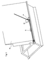
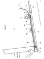
- a hollow profile bar 53 on a conveyor track 54 arranged at the lower end of a support wall 60 is up to a stop 57 in the area of a bending point 58/59 transported
- the stop 57 can also in front of the bending point in the conveyor track his.
- the stop 57 can with a Switch to be equipped of the feed conveyor (not shown) stops and the detection of the hollow profile bar 53 triggers by the gripper 51. So will the hollow profile bar 53 from the gripper 51 in a precisely defined Location recorded.
- the transported beyond the bending point 58/59 Section 53 'of the hollow profile bar 53 is on the Support wall 60 adjacent to the bending lever 59 Abutment 58 bent around.
- the bending point owns preferably that described below with reference to FIGS. 3 to 8 Construction.
- the device can, for example have the structure known from DE-GM 87 05 796 and a support finger (indicated in Fig. 9) have, as he also in the known device is provided.
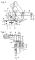
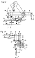
- the device shown in FIGS. 3 to 8 for Bending hollow profile strips 53 consists of a Clamp 2 with a stationary jaw 3 and one opposite to it movable jaw 4 (in 3, the jaw 4 is not shown).
- the moveable Clamping jaw 4 is over guide pins 5 and 6, which are arranged in pairs in the direction of the double arrow 7 displaceable, so that the mouth width the clamp 2 to the width of the hollow profile bar to be bent 53 can be adjusted.
- the bending device also has a hold-down device 20, which serves as an abutment during bending.
- the hold-down device 20 is exchangeable in a carrier 21 used.
- a groove 23 is in the carrier 21 recessed into which the hold-down 20 with sliding fit can be used and for example by a screw 24 is held.
- the carrier 21 for the hold-down device 20 is on one Lever 25 mounted around a machine frame fixed Warehouse 26, i.e. a camp opposite the stationary jaw 3 of terminal 2 is not movable with the help of a linear motor 27, e.g. one double-acting pressure medium cylinder, in the direction of the double arrow 28 from the continuous in Fig. 3 Lines shown operative position in the in Fig. 3rd Stand-by position shown in dash-dot lines is pivotable.
- a linear motor 27 e.g. one double-acting pressure medium cylinder
- the carrier 21 for the hold-down device 20 perpendicular to the plane of symmetry the terminal 2, namely in the direction of the in Fig. 4th drawn double arrow 29 adjustable.
- a linear motor in the exemplary embodiment shown] a double-acting pressure medium cylinder 32 is provided, whose piston rod 33 via a tie rod 34 is coupled to the carrier 21.
- the hold-down device 20 cannot only in a parallel to the plane of symmetry of terminal 2 Level pivoted (double arrow 28), but also in one to the plane of symmetry of terminal 2 vertical direction (double arrow 29) can be adjusted, so that the hold-down 20 entirely from the Bending area can be moved out.
- the hold-down 20 carries on its front End, that of two inclined surfaces 36, which extend longitudinally of the hold-down device 20 has an acute angle include, is formed, a bead-like Approach 35, which shows as Fig. 6, the upper surface of the Hollow profile 53, which is in the terminal 2 between the Jaws 3 and 4 is clamped before Start of the bending process when swiveling the Hold-down 20 bulges somewhat into its operative position.
- the bending device according to the invention provided that the front end of the Hold-down device 20 and there to the inclined surfaces 36 subsequent, bead-shaped approach 35 something narrower than the clear distance between the facing surfaces of the jaws 3 and 4 of clamp 2. So the side walls 40 of the hollow profile bar 53 to be bent during the bending process is also supported from the inside, as indicated in the section of FIG. 7.
- the bending device according to the invention also has a bending lever 59 with a bending attachment 62, which is pivotable about an axis that with the axis 37 of the bead 35 at the front end of the Hold-down device 20 collapses when it is in its active position is (the surfaces 41 lie on the surfaces 42 of the jaw 3).
- the swivel area of the bending lever 59 is not shown in FIG. 3 90 ° limited, but also goes above out so that after swinging out (arrow 28) and laterally shifting (arrow 29) the hold-down device 20 also acute angles between the two the corner 61 generated in the hollow profile bar 53 adjacent Leg of the hollow profile bar 53 bent can be.
- Terminal 2 opened and the hollow profile bar 53 on the upper guide pins 6 or on the conveyor track 54 transported to the pins 6.
- the inner surfaces of the Jaws 3 and 4 are then on the side surfaces 40 on, the hold-down 20 in its in the 3 and 6 the active position shown moves and bulges the upward-facing wall of the hollow profile strip 53 something down.
- the hollow profile bar 53 is located thus remains in a "zero" position at the same time the gripper 52 mounted on the slide 51 the hollow profile bar 53 firmly in place.
- the stop 57 will now sunk into the conveyor track 54 and the carriage 51 with moves the profile 53 clamped by the gripper 52 now in the direction of the bending lever 59 the distance that a process computer specifies and which corresponds to the length of the frame leg.
- the effectively driven length is from an incremental encoder 56 determined. If the sled 51 reaches the Endpoint of its predetermined and effectively measured Movement, the bending lever 59 bends the protruding Section 53 'along the backwards inclined support wall 60 around that of a process computer predetermined angle upwards.
- the exact measurement of those driven by the slide 51 Distance is determined by an incremental encoder 56, and the movement of the carriage 51 is over this controlled.
- the incremental encoder 56 is on the drive motor 55 or on the movement 54 of the slide 51 assembled.
- the carriage 51 is used, for example, by a Endless toothed belt driven, and is on one guided parallel to the conveyor track 54.
- the engagement of the toothed belt in the drive gear of the drive motor 55 is exact and free of play, so that also directly on the engine-gearbox unit mounted incremental encoder 56 the driven Register the exact distance of the slide 51 can.
- the effective route of the sledge 51 corresponds to the profile length which the process computer intended for a bending process.
- the hollow profile bar 53 turns and this is held by the jaws 3 and 4 , the gripper mounted on the slide 51 is released 52.
- the carriage 51 then travels at high speed to the starting position (reference point) back.
- the gripper 52 grips the hollow profile strip 53 again and the carriage 51 moves after the bending process again exactly the one from the process computer given route before, he the hollow profile bar 53 advances without slip.
- the conveyor track 54 be a simple slideway.
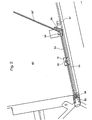
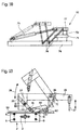
- a hollow profile bar 53 is conveyed by a conveyor, which, for example, the slide 51 with the Gripper 52 can be, for example, starting from the reference position determined by the fitting 57 is so far advanced that the over the Downholder 20 protruding section 53 'of the hollow profile bar 53 who decreased by a certain distance "x" Length of the first leg to be manufactured Spacer frame corresponds.
- This Position is shown in Fig. 9b.
- the lie down Bake 3 and 4 on the hollow profile bar 53 and the Carriage 51 returns to its original position, which in 9a is shown. After this return movement of the carriage 51 is finished, or still during the same, the section 53 'around the hold-down device 20 in the direction of the arrow in Fig. 9b Bending lever 59 bent upwards.
- the hollow profile bar 53rd released from jaws 3 and 4 and the sled 51 moves with from both sides or from above and below to the hollow profile bar 53 Gripper 52 in the position shown in Fig. 9c before, pushing the hollow profile bar 53 so far, that the next (second) position in which in the Hollow profile bar 53 is a corner 61 to create opposite the hold-down device 20 is aligned.
- Now jaws 3 and 4 close again and hold the hollow profile bar 53 immovably and the The next (second) bending process is done with the help of the bending lever 59 executed while the slide 51 returns to its original position.
- the slide 51 with the hollow profile bar 53 applied Gripper 52 by a distance that is the length of the next leg of the spacer frame to be manufactured corresponds so that the next (Third) bending point opposite the hold-down device 20 is aligned.
- the jaws close 3.4 again and hold the hollow profile bar 53, whereupon the third bending process is carried out.
- the fourth bending process is carried out the front end 172 of the supplied hollow profile strip 53 and / or section 173 of the partial finished spacer frame from the Bending plane can be deflected or just the front End 172 is moved down so that the fourth bending process is not hindered.
- At least one corner 61 and with at least one curved section 71 are to be produced (see FIG. 22), can also be used with a hold-down without freely rotatable roller 70, i.e. with a hold-down 20, as shown in Figs. 3 to 8, the at its front end an approach similar or identical to the approach 35, or the like 19 to 21 described below with reference to FIGS. is trained.
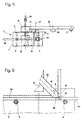
- the bending lever 59 is curved when generating Sections 71 in hollow profile strips 53 opposite the conveying direction of the hollow profile bar 53 according to the desired radius of curvature so slanted so that between the cheeks 3 and 4 emerging hollow profile bar 53 from the bending approach 62 deflected upwards on the bending lever 59 and is continuously curved.
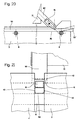
- the width of the roller 70 is, as in particular Fig. Figure 16 shows slightly narrower than the width of the one to be curved Hollow profile bar 53 so that the inner wall the hollow profile bar 53, as can also be seen in FIG. 16, during the curving process inwards is deformed. This will compress the inner wall the hollow profile bar 53 is reduced, so that a largely smooth inner wall in the curved Section 71 of the hollow profile bar 53 results.
- FIG. 18 A particularly favorable embodiment of a Gripper 51, the necessary friction for the exact feed of the hollow profile strip to be curved 53 is shown in Fig. 18. It can be seen that the lower jaw 75 with a in the conveying direction guided on at least one guide rail Carriage 76 is rigidly connected, whereas the upper Cheek 77 over parallelogram 78 through one Pressure motor 79 with respect to the jaw 75 is pivotable away. The movable jaw 77 can therefore pivoted behind the support wall 60 of the device be so that they are the removal of a Completely bent spacer frame is not hindered.
- the stop can 57 based on the conveying direction of the hollow profile bar 53 in front of the tool with the hold-down device 20 or 80 and the bending lever 59 are arranged his.
- the stop 57 with a limit switch is preferred equipped and is based on the conveying direction of the hollow profile bar 53, according to the End of the gripper stroke away from the tool 51.
- a hollow profile strip 53 promoted in the device up to the fitting 57 become, whereupon its switch is operated and controlled by a sequential circuit, the gripper 51 the hollow profile bar 53 in a precisely defined Location takes over.
- the device shown in Figs. 19 to 21 corresponds essentially to that with reference to FIGS. 10 to 17 described device, however, is in the hold-down device 80 instead of the freely rotatable roller 70 a slider 81 inserted through which the inner wall of the Hollow profile bar 53, as shown in Fig. 21, during of the curvature is deformed inwards.
- devices can has been, such as that described with reference to FIGS. 1 to 8 Device to be executed and also how shown in Fig. 9 can be used.
- Both the hold-down 80 with the roller 70, as the hold-down 20 with its neck 35 are also in the conveying direction, i.e. parallel to one of the guide pins 6 connecting level adjustable. So that can the position of the hold-down the geometric conditions be adjusted after changing the angular position of the lever 50 with the ramp surface 62 result.
- a hold-down 20 with extension 35 or a hold-down 80 bending tool equipped with approach 81 can Hollow profile strips 53 also for spacer frames for Insulating glass panes are bent, at least a sharp angled corner 61 and at least one for example after a partial arc have curved portion 71.
- An example for such a frame is shown in Fig. 22.
- the advantage here is that with the invention Device, if the hold-down 20 with the neck 35 or the hold-down device 80 with the attachment 81 is used, even without changing tools sharp corners when creating these corners the feed for the hollow profile bar 53 when moving up of the bending lever 59 shut down - as well (Arc-shaped) curved sections - thereby the feed for the hollow profile bar 53 is more or bending lever 59 pivoted up little actuated with the ramp surface 62 - are produced can.
Abstract
Description
Die Erfindung betrifft ein Verfahren zum Erzeugen kontinuierlich gekrümmter Abschnitte in Hohlprofilleisten, bei dem die Hohlprofilleiste unter einem Niederhalter zwischen Führungsbacken, von unten abgestützt, vorgeschoben und nach dem Niederhalter aus der Förderrichtung der Hohlprofilleiste durch eine zur Förderrichtung schräggestellte Auflauffläche eines Biegehebels abgelenkt wird.The invention relates to a method for generating continuously curved sections in hollow profile strips, in which the hollow profile strip under one Hold-down device between guide jaws, from below supported, pushed forward and after the hold-down device from the conveying direction of the hollow profile bar a ramp surface inclined to the conveying direction a bending lever is deflected.
Einstückig, mit mehr oder weniger scharfkantig
abgebogenen Ecken aus Hohlprofilleisten bestehende
Abstandhalterrahmen sowie Vorrichtungen zum
Herstellen derselben sind aus dem DE-GM 87 05 796,
der DE-PS 32 21 881, der US-PS 4 836 005, der FR-PS
2 449 222 und der DE-OS 32 21 986 bekannt.In one piece, with more or less sharp edges
bent corners consisting of hollow profile strips
Spacer frames and devices for
Manufacture of these are from DE-GM 87 05 796,
DE-PS 32 21 881, US-
Es ist noch auf die DE-OS 33 12 764 zu verweisen, aus der es bekannt ist, Hohlprofilleisten zu Abstandhaltern für Isolierglasscheiben zu biegen, wobei im Bereich der Biegestelle ein von innen gegen die Hohlprofilleiste anlegbarer Dorn vorgesehen ist. Das Biegen erfolgt durch Verschwenken einer Backe, wobei das andere Ende der Profilleiste zwischen einer beweglichen Spannbacke und einem an der Innenseite der Profilleiste anliegenden Widerlager geklemmt wird.It should still be referred to DE-OS 33 12 764 from which it is known to use hollow profile strips for spacers for insulating glass panes, where in the area of the bending point from the inside against the Hollow profile bar attachable mandrel is provided. The Bending is done by pivoting a jaw, whereby the other end of the profile bar between one movable jaw and one on the inside abutment abutting the profile strip becomes.
Ein Problem bei den bekannten Biegevorrichtungen ist es, daß die für die Verwendung bei Isolierglasscheiben geforderten scharfkantigen Abbiegungen nicht immer problemlos erreicht werden können, da zum Teil die Gefahr besteht, daß die Wände der Hohlprofilleiste beim Biegevorgang einreißen und die Seitenflächen der Hohlprofilleisten im Eckbereich, d.h. dort, wo sie gebogen worden sind, nicht immer plan verlaufen, sondern Wellungen aufweisen, welche die nachträgliche Verarbeitung des Abstandhalterrahmens, insbesondere die Beschichtung der Seitenflächen der Abstandhalterrahmen mit Dicht- bzw. Klebemasse erschweren und behindern.A problem with the known bending devices is that for use with insulating glass panes required sharp-edged turns cannot always be easily reached because partly there is a risk that the walls of the hollow profile strip tear during the bending process and the side surfaces the hollow profile strips in the corner area, i.e. not always flat where they have been bent run, but have corrugations that the subsequent processing of the spacer frame, especially the coating of the side surfaces the spacer frame with sealant or adhesive complicate and hinder.
Aus der DE-AS 21 28 717 ist ein Verfahren zum Aufbringen eines metallischen Abstandhalters auf die Scheibenränder einer der rechteckigen Glasplatten einer Isolierverglasung bekannt. Bei diesem Verfahren wird der Abstandhalter for tlaufend mit einer scheibenparallelen Fläche an einem ersten Scheibenrand der horizontal liegenden Glasplatte in Berührung gebracht und anschließend befestigt. Dann wird derAbstandhalter mit einer scheibenparallelen Fläche am nächsten Scheibenrand angelegt und befestigt. Diese Arbeitsschritte werden wiederholt, bis der Abstandhalterrahmen an allen Scheibenrändern befestigt ist. Hierauf wird der Abstandhalter abgeschnitten und seine Enden aneinandergefügt. Bei diesem Verfahren wird so vorgegangen, daß die Glasplatte nach dem Befestigen des Abstandhalters an einem Scheibenrand, jedoch vor ihrer Verschwenkung parallel zu diesem Scheibenrand um eine dessen Länge entsprechenden Strecke verschoben wird, daß die Verschwenkung der Glasplatte jeweils um eine gleiche festgelegte Schwenkachse erfolgt und daß der Abstandhalter um diese Schwenkachse gebogen wird. Dabei wird der Abstandhalter anfangs nur auf einem Teil der Länge des ersten Scheibenrandes angeordnet und der Abstandhalter nach seiner Befestigung an der scheibenparallelen Fläche des letzten Scheibenrandes mit einem Überstand abgeschnitten. Erst dann wird der überstehende Teil um die Schwenkachse der Glasscheibe um 90° gebogen und an der Glasscheibe befestigt.DE-AS 21 28 717 describes a method for Apply a metallic spacer to the Slice edges of one of the rectangular glass plates an insulating glazing known. With this procedure the spacer is continuously with a disc parallel Surface on a first edge of the pane the horizontally lying glass plate and then attached. Then the spacer with a disk-parallel surface on created and fastened the next pane edge. This Steps are repeated until the spacer frame is attached to all edges of the pane. Then the spacer is cut off and its Ends joined together. With this procedure is done so that the glass plate after the Attaching the spacer to a pane edge, however, before being pivoted parallel to this Edge of the pane by a length corresponding to its length Distance is shifted that the pivoting the glass plate is always the same fixed pivot axis and that the spacer is bent about this pivot axis. The spacer is initially only on one Part of the length of the first disc edge arranged and the spacer after it is attached the area of the last pane edge parallel to the pane cut off with a supernatant. First then the protruding part is about the pivot axis the glass pane bent by 90 ° and on the glass pane attached.
Aus der EP-A-332 049 (= DE-A-38 07 529) ist ein
Verfahren mit den Merkmalen des einleitenden Teils
des unabhängigen Anspruches 1 bekannt. Bei der
EP-A-332 049 werden Hohlprofilleisten zu Abstandhaltern
für Isolierglasscheiben gebogen, indem diese
während des Biegens vorgeschoben und ein Biegehebel
oszillierend zum Widerlager hin- und von ihm
wegbewegt wird, wobei während der Wegbewegung
des Biegewerkzeuges das Profil vorgeschoben und
bei der nächsten Bewegung des Biegewerkzeuges
zum Widerlager hin eine Nachbarstelle des Profiles
gegenüber der vorher gebogenen Stelle beaufschlagt
und gebogen wird. Dadurch können je nach Vorschubgeschwindigkeit
des Profiles und der Biegefrequenz
bzw. dem Biegehub des Biegewerkzeuges unterschiedliche
Bögen und Krümmungsradien erzeugt
werden. Es werden aber keine stetig gekrümmten Bögen,
sondern Abschnitte der Hohlprofilleiste erhalten,
die mehrfach abgewinkelt sind.From EP-A-332 049 (= DE-A-38 07 529) is a
Procedure with the features of the introductory part
of
Bekannt sind auch Biegemaschinen für Hohlprofilstäbe, die mit Walzen ausgerüstet sind. So beschreibt die DE-OS 30 34 436 eine Walzenbiegemaschine, die drei drehangetriebene Walzen aufweist, wobei der Hohlprofilstab von zwei Walzen in Anlage an die dritte Walze gehalten wird. Der Radius der Krümmung im Hohlprofilstab entspricht dem Radius der dritten Walze, um die herum der Hohlprofilstab gebogen wurde.Bending machines for hollow profile bars are also known, which are equipped with rollers. So describes DE-OS 30 34 436 a roll bending machine, which has three rotatably driven rollers, the hollow section bar of two rollers in plant is held to the third roller. The radius of the Curvature in the hollow section bar corresponds to the radius the third roller, around which the hollow section bar was bent.
Aus der US-PS 3 885 412 ist es ebenfalls bekannt, einen Hohlprofilstab kontinuierlich zu krümmen, indem er durch eine Anordnung aus drei Walzen bewegt wird. Der Hohlprofilstab wird bei der US-PS 3 885 412 zwischen zwei Walzen durchbewegt, wobei er von der bezogen auf seine Bewegungsrichtung vor dem Walzenpaar angeordneten dritten Walze so belastet wird, daß er beim Durchtritt zwischen den Walzen des Walzenpaares gekrümmt wird. Die einlaufseitige Walze kann verstellt werden, so daß unterschiedliche Krümmungen hergestellt werden können.From US Pat. No. 3,885,412 it is also known to continuously bend a hollow section bar, by going through an arrangement of three rollers is moved. The hollow section rod is used in US Pat. No. 3 885 412 moved between two rollers, whereby he from the related to his direction of movement the third roller arranged third roller so loaded is that it passes between the rollers of the pair of rollers is curved. The inlet side Roller can be adjusted so that different Curvatures can be produced.
Beide bekannten Vorrichtungen arbeiten ausschließlich mit Rollen, wobei auch die Auslenkung durch eine Rolle bewirkt wird. Mit den bekannten Vorrichtungen ist es nicht möglich, Abstandhalterrahmen herzustellen, die gebogene und gerade Abschnitte sowie gegebenenfalls wenigstens eine Ecke besitzen.Both known devices work exclusively with rollers, including the deflection is brought about by a role. With the known devices it is not possible to use spacer frames manufacture the curved and straight sections and possibly have at least one corner.
Aufgabe der Erfindung ist es, ein Verfahren und eine Vorrichtung zur Verfügung zu stellen, mit welchem kontinuierlich gekrümmte Hohlprofilleisten hergestellt werden können, wobei die Krümmungsradien und die Länge des gekrümmten Abschnittes der Hohlprofilleiste weitgehend frei wählbar sind.The object of the invention is a method and to provide a device with which continuously curved hollow profile strips can be, the radii of curvature and the length of the curved section of the hollow profile strip are largely freely selectable.
Gelöst wird diese Aufgabe bei einem Verfahren
der eingangs genannten Gattung durch die
im kennzeichnenden Teil des Anspruches 1
genannten Merkmale.This problem is solved in a process
of the type mentioned at the beginning by the
in the characterizing part of
Gegenüber der Arbeitsweise vorbekannter Biegevorrichtungen besitzt das erfindungsgemäße Verfahren erhebliche Vorteile. So können anders als bei der EP-A-33 20 49 kontinuierlich (stetig) gekrümmte Abschnitte erzeugt werden.Compared to the operation of previously known bending devices has the inventive method significant benefits. So different from EP-A-33 20 49 continuously (continuously) curved Sections are created.
Im Vergleich zu den aus der DE-OS 30 34 436 und der US-PS 3 885 412 bekannten Arbeitsweise ist bei der Erfindung von Vorteil, daß der Krümmungsradius und/oder die Länge der Krümmung sehr einfach eingestellt werden können. Ein weiterer Vorteil besteht in dem erfindungsgemäßen Vorschlag, das Ausfenken mit Hilfe einer Auflauffläche statt wie bekannt mit Rollen zu bewirken. Dies insbesondere im Hinblick darauf, daß die Auflauffläche als Teil des verschwenkbaren Biegehebels dann ohne weiteres auf den gewünschten Auslenkwinkel eingestellt werden kann.In comparison to those from DE-OS 30 34 436 and U.S. Patent 3,885,412 is known operation advantageous in the invention that the radius of curvature and / or the length of the curvature very easily can be adjusted. Another advantage is there in the proposal according to the invention that Ausffen with the help of a ramp instead of as known to effect with roles. This especially in In view of the fact that the ramp surface is part of the pivotable Bending lever then open easily the desired deflection angle can be set can.
Für den Erfolg des erfindungsgemäßen Verfahrens ist es förderlich, wenn die zu krümmende Hohlprofilleiste von einer Vorschubvorrichtung, die vorteilhaft als Greifer ausgebildet ist oder einen Greifer aufweist, vorgeschoben wird. Dies erspart einerseits Antriebe für die Rollen, wie diese für die bekannten Vorrichtungen nötig sind und bietet gegenüber einem Ziehen der Hohlprofilleiste den Vorteil, daß in dieser hergestellte gekrümmte bzw. abgebogene Bereiche (Ecken) nicht wieder verformt werden.For the success of the method according to the invention it is beneficial if the hollow profile strip to be curved from a feed device that is advantageous is designed as a gripper or has a gripper, is advanced. On the one hand, this saves drives for the roles, like this for the known devices are necessary and offers versus pulling the hollow profile strip has the advantage that manufactured in this curved or bent areas (Corners) are not deformed again.
Eine zum Durchführen des erfindungsgemäßen
Verfahrens geeignete Vorrichtung geht aus von der
DE-A-38 07 529, aus der die Merkmale des einleitenden
Teils von Anspruch 6 bekannt sind. Von dieser bekannten
Vorrichtung unterscheidet sich die erfindungsgemäße
Vorrichtung durch die im kennzeichnenden
Teil des Anspruches 6 genannten Merkmale.One for performing the invention
Appropriate method starts from the
DE-A-38 07 529, from which the features of the introductory part
Part of
Vorteilhafte Ausgestaltungen des Verfahrens der Erfindung und zur Durchführung des Verfahrens geeignete Vorrichtungen sind Gegenstand der Unteransprüche.Advantageous refinements of the method of Invention and suitable for performing the method Devices are the subject of the dependent claims.
Beim erfindungsgemäßen Verfahren wird die zum Abstandhalterrahmen zu biegende Hohlprofilleiste beim Biegevorgang von der Vorschubvorrichtung (Greifer) genau um die erforderliche Strecke vorgeschoben, die z.B. dem jeweiligen gekrümmten Abschnitt des Abstandhalterrahmens entspricht. Falls die Länge des gekrümmten Abschnittes größer ist als der maximale Hub des Greifers, wird die Profilleiste in zwei oder allenfalls mehr als zwei Schritten vorgeschoben. Dabei kann so vorgegangen werden, daß der erste (oder die ersten) Hub (Hübe) einer vorgegebenen Länge (dem maximalen Hub) entsprechen und der letzte Hub an die benötigte Länge des gekrümmten Rahmenabschnittes angepaßt wird.In the method according to the invention hollow profile strip to be bent to the spacer frame during the bending process from the feed device (Gripper) advanced exactly the required distance, e.g. the respective curved section of the spacer frame. If the length of the curved section is greater than the maximum stroke of the gripper, the profile bar is in two or at most more than two steps forward. It can be done in such a way that the first (or the first) strokes of a given one Length (the maximum stroke) and the last stroke to the required length of the curved Frame section is adjusted.
Weitere Einzelheiten und Merkmale von
Ausführungs beispielen der Vorrichtung und des Verfahrens
der Erfindung und weitere damit erzielte Vorteile
ergeben sich aus der nachstehenden Beschreibung
von in den Zeichnungen gezeigten Ausführungsformen:
Es zeigt
In einer in den Fig. 1 und 2 gezeigten Vorrichtung
wird eine Hohlprofilleiste 53 auf einer Förderbahn 54,
die am unteren Ende einer Stützwand 60 angeordnet
ist, bis zu einem Anschlag 57 im Bereich einer Biegestelle
58/59 transportiert Der Anschlag 57 kann auch
vor der Biegestelle in die Förderbahn versenkbar angeordnet
sein. Der Anschlag 57 kann mit einem
Schalter ausgestattet sein, der den Zufuhrförderer
(nicht gezeigt) stillsetzt und das Erfassen der Hohlprofilleiste
53 durch den Greifer 51 auslöst. So wird
die Hohlprofilleiste 53 vom Greifer 51 in genau definierter
Lage erfaßt.In a device shown in FIGS. 1 and 2
is a
Der über die Biegestelle 58/59 hinaus transportierte
Abschnitt 53' der Hohlprofilleiste 53 wird an der
Stützwand 60 anliegend vom Biegehebel 59 um ein
Widerlager 58 herum gebogen. Die Biegestelle besitzt
bevorzugt die unten an Hand der Fig. 3 bis 8 beschriebene
Konstruktion.The transported beyond the
Die Vorrichtung kann im übrigen beispielsweise den aus der DE-GM 87 05 796 bekannten Aufbau besitzen und einen Stützfinger (in Fig. 9 angedeutet) aufweisen, wie er auch in der bekannten Vorrichtung vorgesehen ist.The device can, for example have the structure known from DE-GM 87 05 796 and a support finger (indicated in Fig. 9) have, as he also in the known device is provided.
Die in den Fig. 3 bis 8 gezeigte Vorrichtung zum
Biegen von Hohlprofilleisten 53 besteht aus einer
Klemme 2 mit einer ortsfesten Klemmbacke 3 und einergegenüberdieser
beweglichen Klemmbacke 4 (in
Fig. 3 istdie Klemmbacke 4 nicht gezeigt). Die bewegliche
Klemmbacke 4 ist über Führungsstifte 5 und 6,
die jeweils paarweise angeordnet sind, in Richtung
des Doppelpfeils 7 verschiebbar, so daß die Maulweite
der Klemme 2 an die Breite der zu biegenden Hohlprofilleiste
53 angepaßt werden kann.The device shown in FIGS. 3 to 8 for
Bending hollow profile strips 53 consists of a
Zur Betätigung der beweglichen Klemmbacke 4
in Richtung des Pfeiles 7 (Fig. 4) ist ein an der feststehenden
Klemmbacke 3 verschwenkbar abgestützter
Hebel 8 vorgesehen, der über eine Zugstange 9,
die über ein Lager 10 schwenkbeweglich an der beweglichen
Klemmbacke 4 abgestützt ist, gekuppelt
ist. Der Schwenkhebel 8 wird durch einen nicht gezeigten
Linearmotor, z.B. einen doppelt wirkenden
Druckmittelzylinder, betätigt.To actuate the
Die Biegevorrichtung besitzt weiters einen Niederhalter
20, der beim Biegen als Widerlager dient.
Der Niederhalter 20 ist auswechselbar in einem Träger
21 eingesetzt. Hiezu ist im Träger 21 eine Nut 23
ausgespart, in die der Niederhalter 20 mit Gleitsitz
einsetzbar ist und beispielsweise durch eine Schraube
24 gehalten wird.The bending device also has a hold-down
Der Träger 21 für den Niederhalter 20 ist an einem
Hebel 25 montiert, der um ein maschinengestellfestes
Lager 26, d.h. ein Lager, das gegenüber der
ortsfesten Klemmbacke 3 der Klemme 2 nicht beweglich
ist, mit Hilfe eines Linearmotors 27, z.B. einem
doppelt wirkenden Druckmittelzylinder, in Richtung
des Doppelpfeiles 28 aus der in Fig. 3 in durchgehenden
Linien dargestellten Wirkstellung in die in Fig. 3
strichpunktiert eingezeichnete Bereitschaftsstellung
verschwenkbar ist.The
Zusätzlich ist der Träger 21 für den Niederhalter
20, wie dies Fig. 4 zeigt, senkrecht zur Symmetrieebene
der Klemme 2, nämlich in Richtung des in Fig. 4
eingezeichneten Doppelpfeiles 29 verstellbar. Hiezu
ist der Träger 21 über Führungen 30 in einer mit dem
Hebel 25 verbundenen Halterung 31 verschiebbar
geführt. Zur Verstellung des Trägers 21 und damit des
Niederhalters 20 in Richtung des Doppelpfeiles 29 ist
ein Linearmotor, im gezeigten Ausführungsbeispie]
ein doppelt wirkender Druckmittelzylinder 32, vorgesehen,
dessen Kolbenstange 33 über eine Zugstange
34 mit dem Träger 21 gekuppelt ist.In addition, the
Auf diese Weise kann der Niederhalter 20 nicht
nur in einer zur Symmetrieebene der Klemme 2 parallelen
Ebene verschwenkt (Doppelpfeil 28), sondern
auch in einer zur Symmetrieebene der Klemme 2
senkrechten Richtung (Doppelpfeil 29) verstellt werden,
so daß der Niederhalter 20 zur Gänze aus dem
Biegebereich herausbewegt werden kann.In this way, the hold-down
Wie die Fig. 3 und 4 und insbesondere Fig. 6
zeigt, trägt der Niederhalter 20 an seinem vorderen
Ende, das von zwei Schrägflächen 36, die zur Längserstreckung
des Niederhalters 20 einen spitzen Winkel
einschließen, gebildet wird, einen wulstartigen
Ansatz 35, der wie Fig. 6 zeigt, die obere Fläche des
Hohlprofils 53, das in der Klemme 2 zwischen den
Klemmbacken 3 und 4 geklemmt ist, noch vor dem
Beginn des Biegevorganges beim Einschwenken des
Niederhalters 20 in seine Wirkstellung etwas einwölbt.Like FIGS. 3 and 4 and in particular FIG. 6
shows, the hold-down 20 carries on its front
End, that of two
Zusätzlich ist bei der erfindungsgemäßen Biegevorrichtung
vorgesehen, daß das vordere Ende des
Niederhalters 20 und der dort an die Schrägfächen 36
anschließende, wulstförmige Ansatz 35 etwas
schmäler ausgebildet als der lichte Abstand zwischen
den einander zugekehrten Flächen der Klemmbacken
3 und 4 der Klemme 2. So werden die Seitenwände
40 der zu biegenden Hohlprofilleiste 53 während
des Biegevorganges auch von innen her abgestützt,
wie dies im Schnitt von Fig. 7 angedeutet ist.
Dies ist insbesondere beim Biegen von Hohlprofilleisten
53 zu Abstandhalterrahmen für Isolierglasscheiben
von Bedeutung, da die Breite der Seitenflächen
40 der Hohlprofilleiste 53 auch im Eckbereich möglichst
nicht verkleinert werden soll und diese Seitenflächen
40 im Eckbereich nicht aus der von den Seitenflächen
40 im Bereich der Ecke definierten Ebenen
nach innen abweichen sollen, damit das vor dem
Zusammenbau der Isolierglasscheiben auf die Seitenflächen
40 des Abstandhalterrahmens aufzubringende
Klebe- und Dichtmaterial auch im Eckbereich,
der bekanntlich für die Dichtheit von Isolierglasscheiben
von erheblicher Bedeutung ist, in der vollen Breite
aufgebracht werden kann.In addition, the bending device according to the invention
provided that the front end of the
Hold-
Um den Niederhalter 20, insbesondere dessen
wulstförmigen Ansatz 35, gegenüber der Klemmbacke
2 und damit gegenüber der Achse 37 (Fig. 5),
um welche die Hohlprofilleiste 53 gebogen wird, richtig
auszurichten, ist am Niederhalter 20 im Bereich
seines vorderen Endes auf einer Seite eine gewinkelte
Anschlagfläche 41 vorgesehen, die mit einer Stufe
42 an der feststehenden Klemmbacke 3 zusammenwirkt.
Wenn die Anschlagfläche 41 an der Stufe 42
der Klemmbacke 3 anliegt, dann ist die Achse 37 des
am vorderen Ende des Niederhalters 20 vorgesehenen,
wulstförmigen Ansatzes 35 richtig ausgerichtet. To the hold-down
Die erfindungsgemäße Vorrichtung zum Biegen
besitzt noch einen Biegehebel 59 mit einem Biegeansatz
62, der um eine Achse verschwenkbar ist, die mit
der Achse 37 des Wulstes 35 am vorderen Ende des
Niederhalters 20 zusammenfällt, wenn dieser in seinerWirkstellung
ist (die Flächen 41 liegen an den Flächen
42 der Klemmbacke 3 an). Der Verschwenkbereich
des Biegehebels 59 ist nicht auf die in Fig. 3 gezeigten
90° beschränkt, sondern geht auch darüber
hinaus, so daß nach dem Ausschwenken (Pfeil 28)
und seitlichen Verschieben (Pfeil 29) des Niederhalters
20 auch spitze Winkel zwischen den beiden an
die in der Hohlprofilleiste 53 erzeugte Ecke 61 angrenzenden
Schenkel der Hohlprofilleiste 53 gebogen
werden können.The bending device according to the invention
also has a bending
Bei Verwendung der Vorrichtung zum Abbiegen
einer Hohlprofilleiste 53 zu einer Ecke 61 wird die
Klemme 2 geöffnet und die Hohlprofilleiste 53 auf die
oberen Führungsstifte 6 aufgelegt oder auf der Förderbahn
54 zu den Stiften 6 transportiert. Nach dem
Schließen der Klemme 2, die Innenflächen der
Klemmbacken 3 und 4 liegen dann an den Seitenflächen
40 an, wird der Niederhalter 20 in seine in den
Fig. 3 und 6 gezeigte Wirkstellung bewegt und wölbt
dabei die nach oben weisende Wand der Hohlprofilleiste
53 etwas nach unten ein. Hierauf wird durch
Verschwenken des Biegehebels 59 der aus der Klemme
2 ragende Abschnitt 53' der Hohlprofilleiste 53 unter
Ausbilden einer Ecke 61 verschwenkt. Soll der
Winkel an der Ecke 61 ein spitzer sein, so wird der
Niederhalter 20 zurückgeschwenkt und seitlich zurückgezogen,
worauf das Biegen bis zum gewünschten
Winkel fortgesetzt wird.When using the turning device
a
Wenn die Ecke 61 fertig gebogen ist, wird der Biegehebel
59 zurückgeschwenkt, die Klemme 2 geöffnet
und die Hohlprofilleiste 53 vom Greifer 52 vorgeschoben,
bis die Stelle der Hohlprofilleiste 53, in der
die nächste Ecke 61 herzustellen ist, gegenüber dem
Biegewerkzeug richtig ausgerichtet ist und dann, wie
oben beschrieben, die nächste Ecke 61 gebogen.
Dies wird fortgesetzt, bis ein Abstandhalterrahmen
mit der gewünschten Anzahl der Ecken 61 - meist sind
es vier - fertig gebogen ist.When the
Der Vorschub der Hohlprofilleiste 53 mit der in
den Fig. 1 und 2 gezeigten Vorrichtung geht wie folgt
vor sich:The feed of the
Die von der Förderbahn 54 am unteren Rand der
Stützwand 60 herangeförderte Hohlprofilleiste 53
fährt zum Endanschlag 57. Die Hohlprofilleiste 53 befindet
sich damit in einer "Null"-Position, Zugleich hält
der am Schlitten 51 montierte Greifer 52 die Hohlprofilleiste
53 in ihrer Lage fest. Der Anschlag 57 wird nun
in die Förderbahn 54 versenkt und der Schlitten 51 mit
dem vom Greifer 52 festgeklemmten Profil 53 verfährt
nun in Richtung des Biegehebels 59 genau um
jene Wegstrecke, die ein Prozeßrechner vorgibt und
die der Länge des Rahmenschenkels entspricht. Die
effektiv gefahrene Länge wird von einem Inkrementalgeber
56 bestimmt. Erreicht der Schlitten 51 den
Endpunkt seiner vorgegebenen und effektiv gemessenen
Bewegung, biegt der Biegehebel 59 den überstehenden
Abschnitt 53' entlang der nach rückwärts
geneigten Stützwand 60 um den von einem Prozeßrechner
vorgegebenen Winkel nach oben.The of the
Die genaue Messung der vom Schlitten 51 gefahrenen
Wegstrecke ermittelt ein Inkrementalgeber 56,
und die Bewegung des Schlittens 51 wird über diesen
gesteuert. Der Inkrementalgeber 56 ist am Antriebsmotor
55 oder an der Bewegung 54 des Schlittens 51
montiert.The exact measurement of those driven by the
Der Schlitten 51 wird beispielsweise von einem
Endlos-Zahnriemen angetrieben, und ist auf einer
parallel zur Förderbahn 54 verlaufenden Führung geführt.The
Der Eingriff des Zahnriemens in das Antriebszahnrad
des Antriebsmotors 55 ist exakt und spielfrei,
so daß auch ein unmittelbar an der Motor-Getriebe-Einheit
montierter Inkrementalgeber 56 die gefahrene
Wegstrecke des Schlittens 51 genau registrieren
kann. Die effektiv zu fahrende Strecke des Schlittens
51 entspricht jener Profillänge, welche der Prozeßrechner
für einen Biegevorgang bestimmt.The engagement of the toothed belt in the drive gear
of the
Gleich vorteilhaft ist auch die Anwendung einer
Zahnstange, die an der Führung des Schlittens 51
montiert ist. Bei dieser alternativ anwendbaren Einrichtung
muß der Antriebsmotor 55 nicht ortsfest
montiert sein, sondern kann auch am Schlitten 51 angeordnet
sein. Das Antriebszahnrad des Antriebsmotors
55 greift dann in die an der Führung 54 des Schlittens
51 befestigte Zahnstange ein, wobei ein Inkrementalgeber
56 ebenfalls am Antriebsmotor 55 oder
am Schlitten 51 montiert sein kann.The use of a is equally advantageous
Rack attached to the
Während der Biegehebel 59 die Hohlprofilleiste
53 abbiegt und dieses von den Backen 3 und 4 gehalten
wird, löst sich der am Schlitten 51 montierte Greifer
52. Der Schlitten 51 fährt dann mit hoher Geschwindigkeit
in die Ausgangslage (Referenzpunkt)
zurück. Dann erfaßt der Greifer 52 die Hohlprofilleiste
53 wieder und der Schlitten 51 fährt nach dem Biegevorgang
wieder genau um die vom Prozeßrechner
vorgegebene Wegstrecke vor, wobei er die Hohlprofilleiste
53 schlupffrei vorschiebt.During the bending
Wenn die Hohlprofilleiste 53 in die Vorrichtung
von einer dieser vorgeschalteten Zuführeinrichtung
bis zum Anschlag 57 zugeführt wird, kann die Förderbahn
54 eine einfache Gleitbahn sein.When the
Der Ablauf der Arbeitsschritte beim Herstellen einess rechteckigen Abstandhalterrahmens wird im folgenden beispielsweise an Hand Fig. 9 in mehr Einzelheiten beschrieben:The sequence of the manufacturing steps a rectangular spacer frame is used in the following for example with reference to Fig. 9 in more detail described:
Eine Hohlprofilleiste 53 wird von einer Fördervorrichtung,
die beispielsweise der Schlitten 51 mit dem
Greifer 52 sein kann, beispielsweise ausgehend von
der Referenzlage, die durch den beschlag 57 bestimmt
ist, so weit vorgeschoben, daß der über den
Niederhalter 20 überstehende Abschnitt 53' der Hohlprofilleiste
53 der um eine bestimmte Strecke "x" verminderten
Länge des ersten Schenkels des herzustellenden
Abstandhalterrahmens entspricht. Diese
Stellung ist in Fig. 9b gezeigt. Nun legen sich die
Backen 3 und 4 an die Hohlprofilleiste 53 an und der
Schlitten 51 kehrt in seine Ausgangsstellung, die in
Fig. 9a gezeigt ist, zurück. Nachdem diese Rückbewegung
des Schlittens 51 beendet ist, oder noch während
derselben, wird der Abschnitt 53' um den Niederhalter
20 in Richtung des Pfeiles in Fig. 9b vom
Biegehebel 59 nach oben abgebogen. Nachdem der
Biegevorgang beendet ist, wird die Hohlprofilleiste 53
von den Backen 3 und 4 freigegeben und der Schlitten
51 bewegt sich mit von den beiden Seiten oder von
oben und unten her an die Hohlprofilleiste 53 angelegtem
Greifer 52 in die in Fig. 9c gezeigte Stellung
vor, wobei er die Hohlprofilleiste 53 so weit vorschiebt,
daß die nächste (zweite) Stelle, in der in der
Hohlprofilleiste 53 eine Ecke 61 zu erzeugen ist, gegenüber
dem Niederhalter 20 ausgerichtet ist. Nun
schließen sich die Backen 3 und 4 wieder und halten
die Hohlprofilleiste 53 unverschiebbar fest und der
nächste (zweite) Biegevorgang wird mit Hilfe des Biegehebels
59 ausgeführt, während der Schlitten 51
wieder in seine Ausgangsstellung zurückkehrt. Nachdem
der zweite Biegevorgang beendet ist, bewegt
sich der Schlitten 51 mit an der Hohl profilleiste 53 angelegten
Greifer 52 um eine Strecke vor, die der Länge
des nächsten Schenkels des herzustellenden Abstandhalterrahmens
entspricht, so daß die nächste
(dritte) Biegestelle gegenüber dem Niederhalter 20
ausgerichtet ist. Es schließen sich die Klemmbacken
3,4 wieder und halten die Hohlprofilleiste 53 fest, worauf
der dritte Biegevorgang ausgeführt wird.A
Nachdem der dritte Biegevorgang beendet ist, lösen
sich die Backen 3 und 4 wieder von der Hohlprofilleiste
53 und der Schlitten 51 bewegt sich wieder mit
an die Hohlprofilleiste 53 angelegtem Greifer 52 so
weit vor, daß die nächste (vierte) Biegestelle gegenüber
dem Niederhalter 20 genau ausgerichtet ist.After the third bending process is finished, loosen
the
Beim Herstellen eines rechteckigen Abstandhalterrahmens,
wie dies in Fig. 9 gezeigt ist, entspricht
dieser Hub genau dem Hub vor der Ausführung des
zweiten Biegevorganges. Nachdem der Vorschub der
Hohlprofilleiste 53 wie beschrieben ausgeführt worden
ist und die nächste Biegestelle (die vierte) gegenüber
dem Niederhalter 20 ausgerichtet worden ist,
schließen sich die Backen 3 und 4 wieder und halten
die Hohlprofilleiste 53 fest. Nun wird die Hohlprofilleiste
53 an der durch den Pfeil 170 gekennzeichneten
Stelle (Fig. 9e) abgeschnitten. Die Länge des so erhaltenen
in Fig. 9e links vom Niederhalter 20 befindlichen
Stückes der Hohlprofilleiste 53 entspricht genau
der vorbestimmten Strecke "x", um welche die
Hohlprofilleiste 53 vor dem ersten Biegevorgang (Fig.
9b) weniger weit vorgeschoben wurde als der Länge
des ersten Schenkels (Fig. 9b) entspricht.When making a rectangular spacer frame,
as shown in Fig. 9 corresponds
this stroke exactly the stroke before the execution of the
second bending process. After the feed of the
Nun wird der vierte Biegevorgang ausgeführt,
wobei das vordere Ende 172 der zugeführten Hohlprofilleiste
53 und/oder der Abschnitt 173 des teilweise
fertiggestellten Abstandhalterrahmens aus der
Biegeebene ausgelenkt werden oder einfach das vordere
Ende 172 nach unten bewegt wird, damit der
vierte Biegevorgang nicht behindert wird.Now the fourth bending process is carried out
the front end 172 of the supplied
Nachdem der vierte Biegevorgang beendet ist,
wird der bis auf das Verbinden der beiden an der
Stoßstelle 171 (Fig. 9f) aneinandergrenzenden Enden
der Hohlprofilleiste 53 fertiggestellte Abstandhalterrahmen
aus der Vorrichtung abtransportiert, nachdem
die Backen 3 und 4 wieder gelöst und der Niederhalter
20 aus der Biegeebene entfernt worden
sind. Die an der Stoßstelle 171 aneinandergrenzenden
Enden der zum Abstandhalterrahmen gebogenen
Hohlprofilleiste 53 werden durch Einstecken eines
Verbinders oder durch Stumpfverschweißen miteinander
verbunden. Eine hiezu geeignete Schweißvorrichtung
ist beispielsweise aus der EP-A-0 192
921 bekannt.After the fourth bending process is finished,
except for connecting the two on the
Butt joint 171 (Fig. 9f) adjacent ends
the
Wenn mit der an Hand der Fig. 1 bis 8 beschriebenen
Vorrichtung in Hohlprofilleisten 53 gekrümmte
Abschnitte 71 erzeugt werden sollen, wird in den Träger
21 des Werkzeuges ein Niederhalter 80 eingesetzt,
der an seinem freien, der Hohlprofilleiste 53 zugekehrten
Ende eine frei drehbare Rolle 70 (Fig. 10
bis 17) aufweist. Durch diese Rolle 70 wird die Hohlprofilleiste
53, die zwischen den Backen 3 und 4 geführt
ist - d.h. die Backen 3 und 4 klemmen die Hohlprofilleiste
53 nicht mehr - gegen die als Abstützung
von unten dienenden Führungsstangen 6 gehalten.If with that described with reference to FIGS. 1 to 8
Device in hollow profile strips 53
Insbesondere wenn Abstandhalterrahmen mit
wenigstens einer Ecke 61 und mit wenigstens einem
gekrümmten Abschnitt 71 hergestellt werden sollen
(vgl. Fig. 22), kann auch mit einem Niederhalter ohne
frei drehbare Rolle 70, d.h. mit einem Niederhalter 20,
wie er in Fig. 3 bis 8 gezeigt ist, gearbeitet werden, der
an seinem vorderen Ende einen Ansatz ähnlich oder
identisch dem Ansatz 35 aufweist, oder der wie weiter
unten mit Bezug auf die Fig. 19 bis 21 beschrieben ist,
ausgebildet ist.Especially when using spacer frames
at least one
Der Biegehebel 59 wird beim Erzeugen von gekrümmten
Abschnitten 71 in Hohlprofilleisten 53 gegenüber
der Förderrichtung der Hohlprofilleiste 53
entsprechend dem gewünschten Krümmungsradius
so schräg gestellt, so daß die zwischen den Backen
3 und 4 austretende Hohlprofilleiste 53 vom Biegeansatz
62 am Biegehebel 59 nach oben abgelenkt und
dabei kontinuierlich gekrümmt wird.The bending
Wesentlich für das erfolgreiche Biegen der Hohlprofilleiste
53 zu einem gekrümmten Abschnitt 71 derselben
ist es, daß diese vom Greifer 51 im wesentlichen
kontinuierlich und genau um das dem gekrümmten
Abschnitt 71 der Hohlprofilleiste 53 entsprechende
Stück vorgeschoben wird.Essential for the successful bending of the
Die Breite der Rolle 70 ist, wie insbesondere Fig.
16 zeigt, etwas schmäler als die Breite der zu krümmenden
Hohlprofilleiste 53, so daß die Innenwand
der Hohlprofilleiste 53, wie ebenfalls aus Fig. 16 ersichtlich,
während des Krümmvorganges nach innen
verformt wird. Dadurch wird die Stauchung der Innenwand
der Hohlprofilleiste 53 verringert, so daß sich
eine weitgehend glatte Innenwand im gekrümmten
Abschnitt 71 der Hohlprofilleiste 53 ergibt.The width of the
Eine besonders günstige Ausführungsform eines
Greifers 51, der den nötigen Reibungsschluß für den
genauen Vorschub der zu krümmenden Hohlprofilleiste
53 sicherstellt, ist in Fig. 18 gezeigt. Es ist ersichtlich,
daß die untere Backe 75 mit einem in Förderrichtung
auf wenigstens einer Führungsschiene geführten
Schlitten 76 starr verbunden ist, wogegen die obere
Backe 77 über Parallelogrammlenker 78 durch einen
Druckmittelmotor 79 gegenüber der Backe 75
wegschwenkbar ist. Die bewegliche Backe 77 kann
daher hinter die Stützwand 60 der Vorrichtung verschwenkt
werden, so daß sie den Abtransport eines
fertig gebogenen Abstandhalterrahmens nicht behindert.A particularly favorable embodiment of a
Wie bereits weiter oben angedeutet, kann derAnschlag
57, bezogen auf die Förderrichtung der Hohlprofilleiste
53 vor dem Werkzeug mit dem Niederhalter
20 oder 80 und dem Biegehebel 59 angeordnet
sein. Bevorzugt ist der Anschlag 57 mit einem Endschalter
ausgestattet und befindet sich, bezogen auf
die Förderrichtung der Hohlprofilleiste 53, nach dem
vom Werkzeug entfernten Ende des Hubes des Greifers
51. Auf diese Art und Weise kann eine Hohlprofilleiste
53 in die Vorrichtung bis zum beschlag 57 gefördert
werden, worauf dessen Schalter betätigt wird
und durch eine Folgeschaltung gesteuert, der Greifer
51 die Hohlprofilleiste 53 in einer genau definierten
Lage übernimmt.As already indicated above, the stop can
57, based on the conveying direction of the
Es ist ersichtlich, daß durch Austausch des Niederhalters
80 mit der Rolle 70 durch den Niederhalter
20 der in den Fig. 1 bis 8 gezeigten Ausführungsform
Abstandhalterrahmen mit wenigstens einer scharf
geknickten Ecke mit beliebigen Winkeln zwischen
den an die Ecke 61 angrenzenden Schenkeln des Abstandhalterrahmens
und mit wenigstens einem gekrümmten
Abschnitt 71 aus ein- und derselben Hohlprofilleiste
53 erzeugt werden können.It can be seen that by replacing the hold-down
Um den Werkzeugwechsel (Austausch des Niederhalters
80 mit der Rolle 70 gegen den Niederhalter
20 ohne Rolle) zu vermeiden, können am Träger 21
sowohl ein Niederhalter 80 als auch ein Niederhalter
20 montiert sein. Diese Werkzeuge werden dann fallweise
in die Wirklage, die zu den Backen 3 und 4 symmetrisch
ist, bewegt Dies stellt keine Schwierigkeiten
dar, da der Träger 21, wie weiter oben an Hand der
Fig. 1 bis 8 beschrieben, anhebbar und quer zur Biegeebene
verstellbar ist.To change the tool (exchange the hold-down
80 with the
Die in den Fig. 19 bis 21 dargestellte Vorrichtung
entspricht im wesentlichen der an Hand der Fig. 10 bis
17 beschriebenen Vorrichtung, jedoch ist im Niederhalter
80 anstatt der frei drehbaren Rolle 70 ein Gleitstück
81 eingesetzt, durch das die Innenwand der
Hohlprofilleiste 53, wie aus Fig. 21 ersichtlich, während
des Krümmens nach innen verformt wird.The device shown in Figs. 19 to 21
corresponds essentially to that with reference to FIGS. 10 to
17 described device, however, is in the hold-down
Die an Hand der Fig. 10 bis 21 beschriebenen Vorrichtungen können, wenn nichts anderes erwähnt worden ist, so wie die an Hand der Fig. 1 bis 8 beschriebene Vorrichtung ausgeführt sein und auch wie in Fig. 9 gezeigt, verwendet werden.The described with reference to FIGS. 10 to 21 Unless otherwise stated, devices can has been, such as that described with reference to FIGS. 1 to 8 Device to be executed and also how shown in Fig. 9 can be used.
Sowohl der Niederhalter 80 mit der Rolle 70, als
auch der Niederhalter 20 mit seinem Ansatz 35 sind
in Förderrichtung, d.h. parallel zu einer die Führungsstifte
6 verbindenden Ebene verstellbar. Damit kann
die Stellung der Niederhalter den geometrischen Verhältnissen
angepaßt werden, die sich nach dem Ändern
der Winkellage des Hebels 50 mit der Auflauffläche
62 ergeben.Both the hold-down 80 with the
Mit dem erfindungsgemäßen, mit einem Niederhalter
20 mit Ansatz 35 oder einem Niederhalter 80
mit Ansatz 81 ausgestatteten Biegewerkzeug können
Hohlprofilleisten 53 auch zu Abstandhalterrahmen für
Isolierglasscheiben gebogen werden, die wenigstens
eine scharfkantig abgewinkelte Ecke 61 und wenigstens
einen beispielsweise nach einem Teilkreisbogen
gekrümmten Abschnitt 71 aufweisen. Ein Beispiel
für einen solchen Rahmen ist in Fig. 22 gezeigt.
Von Vorteil ist dabei, daß mit der erfindungsgemäßen
Vorrichtung, soferne der Niederhalter 20 mit dem Ansatz
35 oder der Niederhalter 80 mit dem Ansatz 81
verwendet wird, auch ohne Werkzeugwechsel
scharfkantige Eckenbeim Erzeugen dieser Ecken ist
der Vorschub für die Hohlprofilleiste 53 beim Hochbewegen
des Biegehebels 59 stillgesetzt - als auch
(kreisbogenförmig) gekrümmte Abschnitte - dabei
wird der Vorschub für die Hohlprofilleiste 53 bei mehr
oder wenig stark hochgeschwenktem Biegehebel 59
mit der Auflauffläche 62 betätigt - hergestellt werden
können.With the invention, with a hold-down
20 with
Claims (20)
- Method of obtaining continuously curved portions (71) in hollow-section strips, in which the hollow-section strip (53) is advanced, with support from below, under a holding-down clamp (20, 80) between guide jaws (3, 4) and, subsequent to the holding-down clamp (20, 80), is deflected out of the feed direction of the hollow-section strip (53) by means of a ramp surface (62) of a bending lever (59) oriented obliquely to the said feed direction, characterised in that during the curving procedure the ramp surface (62) is stationary in its operative position, in that the wall of the hollow-section strip (53) on the external side of the curve slides along the obliquely-positioned ramp surface (62) during the entire curving procedure, and in that, during curving of the hollow-section strip (53) the wall of the said hollow-section strip (53) on the inside of the curve is deformed by the holding-down clamp (20, 80) in the direction of the wall of the hollow-section strip (53) on the outside of the curve.
- Method according to claim 1, characterised in that the radius of curvature is set by the degree of deflection of the hollow-section strip (53).
- Method according to claim 1 or 2, characterised in that the length of the curved portion (71) of the hollow-section strip (53) is set by the degree of feed advance of the hollow-section strip, with deflection of the hollow-section strip (53) after the holding-down clamp (20, 80).
- Method for producing spacer frames for insulated glass panels having at least one curved portion (71) and at least one sharply-angled corner (61), characterised in that, when producing the arcuate curved portion (71), the hollow-section strip (53) is advanced under the holding-down clamp (20, 80) between guide jaws (3, 4), and the hollow-section strip (53) is deflected after the holding-down clamp (20, 80), using the method according to one of claims 1 to 3, out of the feed direction of the hollow-section strip (53), and in that, in order to produce a sharply-angled corner (61) in the hollow-section strip (53) the portion of the hollow-section strip (53) projecting beyond the holding-down clamp (20, 80) is bent at an angle, the bending lever (59) being pivoted, with the ramp surface (62) abutting against the projection portion of the hollow-section strip (53), through the desired angle, the said hollow-section strip (53) being stationary.
- Device for producing curved portions (71) in hollow-section strip (53), more particularly during the production of spacer frames for insulated glass panels, with a substantially horizontal conveyor path (54), with a feed device (51, 52) associated with said conveyor path (54) for conveying the hollow-section strip (53) to a tool which has two guide jaws (3, 4) between which the hollow-section strip (53) is received, with a holding-down clamp (20, 80) for the hollow-section strip (53), the forward end of said clamp abutting when in its operative position against the inner wall facing it of the hollow-section strip (53), and with a lever (59) which may be pivoted upward out of the feed direction, with a ramp surface (62) for the hollow-section strip (53), characterised in that the conveyor path (54) is located at the lower end of a (lateral) support surface (69) for the at least one curved portion (71) of the hollow-section strip (53), in that the guide jaws (3, 4) are disposed on either side of the hollow-section strip (53), in that the holding-down clamp (20, 80) is disposed to be movable and when in its operative position engages with its forward end (35, 70, 81) between the guide jaws (3, 4), so that the forward end (35, 70, 81) of the holding-down clamp (20, 80) may be applied against the inner wall of the hollow-section strip, in that the holding-down clamp (20, 80) has, with respect to the two guide jaws (3, 4), a degree of play, and thus may be applied against the inner wall of the hollow-section strip (53), such that the inner wall is deformed during the curving procedure in the direction of the outer wall of the hollow-section strip (53), and in that the bending lever (59) with the ramp surface (62) may be secured in angular positions at will relative to the feed direction of the hollow-section strip (53), for the hollow-section strip (53) emerging from the guide jaws (3, 4), such that during the curving procedure the ramp surface (62) is stationary in its operative position.
- Device according to claim 5, characterised in that the feed device is a gripper (52) which may engage on the hollow-section strip (53), and which is movable to and from on a carriage (51) parallel to the feed direction of the hollow-section strip (53), engaging, during its movement towards the tool, on the hollow-section strip (53).
- Device according to claim 6, characterised in that the gripper (52) has jaws (77, 75) which may be applied from the above and from below to the hollow-section strip (53).
- Device according to claim 7, characterised in that the lower jaw (75) of the gripper (52) is rigidly attached on the carriage (51), and the upper jaw (77) of the gripper (52) is movably mounted on the carriage (51).
- Device according to claim 8, characterised in that the movable jaw (75) is mounted via parallelogram guides (78) on a carriage (76).
- Device according to one of claims 5 to 9, characterised in that the holding-down clamp (20, 80) is secured on a carriage (21) which is adjustable both in or parallel to the plane of symmetry of the guide jaws (3, 4) and also perpendicularly to this plane of symmetry, in order to move the holding-down clamp (20, 80) out of the bending plane.
- Device according to claim 10, characterised in that the carriage (21) for the holding-down clamp (20, 80) is pivotable about an axis (26) perpendicular to the plane of symmetry of the guide jaws (3, 4).
- Device according to claim 10 or 11, characterised in that the carriage (21) for the holding-down clamp (20, 80) is movably guided in a holder (31) perpendicularly to the plane of symmetry of the guide jaws (3, 4).
- Device according to one of claims 10 to 12, characterised in that the carriage (21) for the holding-down clamp (20, 80) is mounted on a lever (25), which is mounted on the device to pivot about an axis (26) perpendicular to the plane of symmetry of the guide jaws (3, 4).
- Device according to one of claims 10 to 13, characterised in that the holding-down clamp (20, 80) is attached on its carriage (21) so as to be exchangeable.
- Device according to one of claims 5 to 14, characterised in that the holding-down clamp (20, 80) carries a slider (35, 81) on its forward end.
- Device according to one of claims 5 to 14, characterised in that the holding-down clamp (20, 80) carries a freely rotatable roller (70) on its forward end.
- Device according to one of claims 10 to 16, characterised in that there are mounted on the carriage (21), as optionally usable holding-down clamps, a holding-down clamp (20) which carries on its forward end a slider (35, 81) abutting against the hollow-section strip (53), and a holding-down clamp (80), which carries on its forward end a freely rotatable roler (70), said holding-down clamps (20, 80) being alternately and optionally adjustable into their operative position engaging between the guide jaws (3, 4).
- Device according to one of claims 15 to 17, characterised in that the slider (35, 81) or the roller (70) is narrower than the hollow-section strip (53).
- Device according to one of claims 15, 17 or 18, characterised in that the slider (35, 81) is curved or rendered convex about at least one axis perpendicular to the feed direction and to the bending plane.
- Device according to one of claims 15 to 19, characterised in that the slider (81) or the roller (70) are interchangeably attached to the holding-down clamp (20, 80).
Applications Claiming Priority (9)
| Application Number | Priority Date | Filing Date | Title |
|---|---|---|---|
| AT112690 | 1990-05-21 | ||
| AT112690A AT397054B (en) | 1990-05-21 | 1990-05-21 | DEVICE FOR BENDING HOLLOW PROFILE STRIPS |
| AT1126/90 | 1990-05-21 | ||
| AT1840/90 | 1990-09-10 | ||
| AT184090A AT397775B (en) | 1990-09-10 | 1990-09-10 | Bending device for holder profile rails - incorporates displaceable grab for rails |
| AT184090 | 1990-09-10 | ||
| AT198790 | 1990-10-02 | ||
| AT198790A AT405912B (en) | 1990-10-02 | 1990-10-02 | Method and apparatus for bending hollow sectional strips |
| AT1987/90 | 1990-10-02 |
Publications (3)
| Publication Number | Publication Date |
|---|---|
| EP0459971A1 EP0459971A1 (en) | 1991-12-04 |
| EP0459971B1 EP0459971B1 (en) | 1994-03-09 |
| EP0459971B2 true EP0459971B2 (en) | 2001-12-12 |
Family
ID=27147132
Family Applications (1)
| Application Number | Title | Priority Date | Filing Date |
|---|---|---|---|
| EP91890106A Expired - Lifetime EP0459971B2 (en) | 1990-05-21 | 1991-05-15 | Method and apparatus for obtaining curved parts in hollow section strips |
Country Status (7)
| Country | Link |
|---|---|
| EP (1) | EP0459971B2 (en) |
| JP (1) | JPH0768322A (en) |
| AT (1) | ATE102513T1 (en) |
| DE (2) | DE59101137D1 (en) |
| DK (1) | DK0459971T3 (en) |
| ES (1) | ES2051110T5 (en) |
| NO (1) | NO179493C (en) |
Families Citing this family (8)
| Publication number | Priority date | Publication date | Assignee | Title |
|---|---|---|---|---|
| DK282090A (en) * | 1990-11-28 | 1992-05-29 | Skovgaard & Co As | PROCEDURE AND APPARATUS FOR MANUFACTURING CLOSED DISTRIBUTION FRAMES OF HOLE THICKWICKED PROFILES |
| DE4214205A1 (en) * | 1992-04-30 | 1993-11-04 | Happich Gmbh Gebr | Installation for bending segments of profiled bars etc. - with additional bending station on tables movable in additional directions |
| ES2096268T3 (en) * | 1992-07-16 | 1997-03-01 | Peter Lisec | DEVICE FOR THE MANUFACTURE OF DISTANCING FRAMES FOR INSULATING CRYSTALS FROM HOLLOW PROFILE SLATS. |
| AT406236B (en) † | 1995-10-31 | 2000-03-27 | Lisec Peter | DEVICE FOR BENDING OR CURVING HOLLOW PROFILES |
| DE10137766A1 (en) * | 2001-08-03 | 2003-02-27 | Lenhardt Maschinenbau | Device for bending hollow profile bars |
| DE10236407B4 (en) * | 2002-08-02 | 2007-09-27 | Lenhardt Maschinenbau Gmbh | Device for bending hollow profiled bars |
| CA2924182C (en) * | 2015-04-02 | 2022-12-06 | Lombarda Macchine S.A.S. Di G.B. Lattuada & C. | Method for automatically bending spacer elements for insulating glass panes - double glazings and machine for carrying out the method |
| CN111531858A (en) * | 2020-05-12 | 2020-08-14 | 周立 | Automobile glass clamping strip bending device |
Citations (1)
| Publication number | Priority date | Publication date | Assignee | Title |
|---|---|---|---|---|
| DE3807529A1 (en) † | 1988-03-08 | 1989-09-21 | Bayer Isolierglasfab Kg | METHOD AND DEVICE FOR BENDING HOLLOW SPACER PROFILES |
Family Cites Families (8)
| Publication number | Priority date | Publication date | Assignee | Title |
|---|---|---|---|---|
| US3885412A (en) * | 1973-11-21 | 1975-05-27 | Lawrence T Vance | Method of fabricating curved tubing and product thereof |
| AT360311B (en) * | 1978-09-26 | 1980-01-12 | Seraphin Puempel & Soehne Kg | BENDING DEVICE FOR PRODUCING A DISTANCE HOLDER FOR INSULATING GLASS DISCS |
| CH647428A5 (en) * | 1980-08-15 | 1985-01-31 | Haeusler Ag Chr | Process for bending a sectional bar, apparatus for supporting portions of a sectional bar relative to one another and multi-roll bending machine |
| CH660398A5 (en) * | 1982-01-21 | 1987-04-15 | Peter Lisec | SPACER FRAME FOR INSULATING GLASS PANELS AND METHOD FOR PRODUCING THE SAME AND DEVICE FOR IMPLEMENTING THE METHOD. |
| DE3312764A1 (en) * | 1983-04-09 | 1984-10-18 | Fr. Xaver Bayer Isolierglasfabrik Kg, 7807 Elzach | METHOD AND DEVICE FOR BENDING SPACER PROFILES FOR INSULATING GLASS PANELS |
| AT389662B (en) * | 1985-02-25 | 1990-01-10 | Lisec Peter Glastech Ind | DEVICE FOR BUTT WELDING |
| AT401627B (en) * | 1987-03-09 | 1996-10-25 | Lisec Peter | DEVICE FOR PRODUCING SPACER FRAME FOR INSULATING GLASS DISC |
| DE3740921A1 (en) * | 1987-12-03 | 1989-06-15 | Bayer Isolierglasfab Kg | DEVICE FOR PRODUCING A BEND ON A HOLLOW RECTANGLE PROFILE |
-
1991
- 1991-05-15 DK DK91890106.7T patent/DK0459971T3/en not_active Application Discontinuation
- 1991-05-15 AT AT91890106T patent/ATE102513T1/en not_active IP Right Cessation
- 1991-05-15 DE DE91890106T patent/DE59101137D1/en not_active Expired - Fee Related
- 1991-05-15 ES ES91890106T patent/ES2051110T5/en not_active Expired - Lifetime
- 1991-05-15 EP EP91890106A patent/EP0459971B2/en not_active Expired - Lifetime
- 1991-05-16 NO NO911925A patent/NO179493C/en not_active Application Discontinuation
- 1991-05-21 DE DE4116521A patent/DE4116521C2/en not_active Expired - Fee Related
- 1991-05-21 JP JP3145531A patent/JPH0768322A/en active Pending
Patent Citations (1)
| Publication number | Priority date | Publication date | Assignee | Title |
|---|---|---|---|---|
| DE3807529A1 (en) † | 1988-03-08 | 1989-09-21 | Bayer Isolierglasfab Kg | METHOD AND DEVICE FOR BENDING HOLLOW SPACER PROFILES |
Also Published As
| Publication number | Publication date |
|---|---|
| EP0459971A1 (en) | 1991-12-04 |
| DE4116521C2 (en) | 1998-07-23 |
| NO179493C (en) | 1996-10-16 |
| DE59101137D1 (en) | 1994-04-14 |
| ES2051110T3 (en) | 1994-06-01 |
| DK0459971T3 (en) | 1994-04-05 |
| ATE102513T1 (en) | 1994-03-15 |
| NO179493B (en) | 1996-07-08 |
| NO911925D0 (en) | 1991-05-16 |
| ES2051110T5 (en) | 2002-07-16 |
| EP0459971B1 (en) | 1994-03-09 |
| JPH0768322A (en) | 1995-03-14 |
| NO911925L (en) | 1991-11-22 |
| DE4116521A1 (en) | 1991-11-28 |
Similar Documents
| Publication | Publication Date | Title |
|---|---|---|
| DE3223881C2 (en) | Spacer frame and method and device for bending hollow profile strips to form spacer frames for insulating glass | |
| EP2674279B1 (en) | Method for roll bending a profile, profile, method for manufacturing curved profile workpieces, curved profile workpiece, device for roll bending a profile as well as an extruded and roll bending line | |
| AT403350B (en) | BENDING MACHINE FOR MANUFACTURING A SPACING INTERNAL FRAME FOR AN INSULATED GLASS DISC | |
| EP0121873B1 (en) | Method and apparatus for bending spacekeeping profiles for thermopane glasses | |
| EP0461100B2 (en) | Method and apparatus for bending hollow spacer frames for isolating glass | |
| EP0459971B2 (en) | Method and apparatus for obtaining curved parts in hollow section strips | |
| DE4116268C2 (en) | ||
| EP0579593B1 (en) | Device for fabricating spacing frames out of hollow section strips for insulating glass panes | |
| EP0449801B1 (en) | Apparatus for bending hollow frames for isolating glass | |
| AT406889B (en) | METHOD AND DEVICE FOR PRODUCING SPACER FRAME FOR INSULATING GLASS PANELS FROM HOLLOW PROFILE BARS | |
| EP0249946A2 (en) | Method and device for the fabrication of a spacing frame for insulating glass panes | |
| DE3807529C2 (en) | ||
| EP0771597B2 (en) | Apparatus for bending or curving hollow profiles | |
| AT397775B (en) | Bending device for holder profile rails - incorporates displaceable grab for rails | |
| AT405912B (en) | Method and apparatus for bending hollow sectional strips | |
| AT397055B (en) | METHOD AND DEVICE FOR BENDING HOLLOW PROFILE BARS TO SPACER FRAME FOR INSULATING GLASS PANELS | |
| AT397054B (en) | DEVICE FOR BENDING HOLLOW PROFILE STRIPS | |
| EP1285708B1 (en) | Method and apparatus for bending hollow profiles for spacers for insulated glazing panels | |
| DE102004060805A1 (en) | Hollow section bar e.g. spacer frame, bending device for insulating glass plate, has bending tool with rolls rotated parallel to each other, where shell of one roll has projecting section in center of its section facing outer wall of bar | |
| EP0042450B1 (en) | Process for producing silencer cases with a folded longitudinal seam and apparatus for carrying out this process | |
| DE4117002A1 (en) | Bending device for holder profile rails | |
| DE3627152A1 (en) | Method and apparatus for the production of a spacer frame for insulating glass | |
| AT410909B (en) | Hollow strip bending process involves supporting hollow strip both internally and externally during bending | |
| AT401242B (en) | Apparatus for producing spacer frames for panes of insulating glass from hollow sectional strips | |
| DE10236407B4 (en) | Device for bending hollow profiled bars |
Legal Events
| Date | Code | Title | Description |
|---|---|---|---|
| PUAI | Public reference made under article 153(3) epc to a published international application that has entered the european phase |
Free format text: ORIGINAL CODE: 0009012 |
|
| AK | Designated contracting states |
Kind code of ref document: A1 Designated state(s): AT CH DE DK ES FR GB IT LI SE |
|
| 17P | Request for examination filed |
Effective date: 19911021 |
|
| 17Q | First examination report despatched |
Effective date: 19930430 |
|
| GRAA | (expected) grant |
Free format text: ORIGINAL CODE: 0009210 |
|
| AK | Designated contracting states |
Kind code of ref document: B1 Designated state(s): AT CH DE DK ES FR GB IT LI SE |
|
| REF | Corresponds to: |
Ref document number: 102513 Country of ref document: AT Date of ref document: 19940315 Kind code of ref document: T |
|
| ET | Fr: translation filed | ||
| REG | Reference to a national code |
Ref country code: DK Ref legal event code: T3 |
|
| GBT | Gb: translation of ep patent filed (gb section 77(6)(a)/1977) |
Effective date: 19940303 |
|
| REF | Corresponds to: |
Ref document number: 59101137 Country of ref document: DE Date of ref document: 19940414 |
|
| REG | Reference to a national code |
Ref country code: ES Ref legal event code: FG2A Ref document number: 2051110 Country of ref document: ES Kind code of ref document: T3 |
|
| ITF | It: translation for a ep patent filed |
Owner name: DR. ING. A. RACHELI & C. |
|
| PLBI | Opposition filed |
Free format text: ORIGINAL CODE: 0009260 |
|
| EAL | Se: european patent in force in sweden |
Ref document number: 91890106.7 |
|
| 26 | Opposition filed |
Opponent name: LENHARDT MASCHINENBAU GMBH Effective date: 19941209 |
|
| PLAW | Interlocutory decision in opposition |
Free format text: ORIGINAL CODE: EPIDOS IDOP |
|
| APAE | Appeal reference modified |
Free format text: ORIGINAL CODE: EPIDOS REFNO |
|
| APAC | Appeal dossier modified |
Free format text: ORIGINAL CODE: EPIDOS NOAPO |
|
| APAC | Appeal dossier modified |
Free format text: ORIGINAL CODE: EPIDOS NOAPO |
|
| APAC | Appeal dossier modified |
Free format text: ORIGINAL CODE: EPIDOS NOAPO |
|
| PLAW | Interlocutory decision in opposition |
Free format text: ORIGINAL CODE: EPIDOS IDOP |
|
| APAC | Appeal dossier modified |
Free format text: ORIGINAL CODE: EPIDOS NOAPO |
|
| APAE | Appeal reference modified |
Free format text: ORIGINAL CODE: EPIDOS REFNO |
|
| APAC | Appeal dossier modified |
Free format text: ORIGINAL CODE: EPIDOS NOAPO |
|
| PGFP | Annual fee paid to national office [announced via postgrant information from national office to epo] |
Ref country code: DK Payment date: 20010531 Year of fee payment: 11 |
|
| APAC | Appeal dossier modified |
Free format text: ORIGINAL CODE: EPIDOS NOAPO |
|
| PLAW | Interlocutory decision in opposition |
Free format text: ORIGINAL CODE: EPIDOS IDOP |
|
| PUAH | Patent maintained in amended form |
Free format text: ORIGINAL CODE: 0009272 |
|
| STAA | Information on the status of an ep patent application or granted ep patent |
Free format text: STATUS: PATENT MAINTAINED AS AMENDED |
|
| 27A | Patent maintained in amended form |
Effective date: 20011212 |
|
| AK | Designated contracting states |
Kind code of ref document: B2 Designated state(s): AT CH DE DK ES FR GB IT LI SE |
|
| REG | Reference to a national code |
Ref country code: CH Ref legal event code: AEN Free format text: AUFRECHTERHALTUNG DES PATENTES IN GEAENDERTER FORM |
|
| REG | Reference to a national code |
Ref country code: GB Ref legal event code: IF02 |
|
| PG25 | Lapsed in a contracting state [announced via postgrant information from national office to epo] |
Ref country code: DK Free format text: LAPSE BECAUSE OF FAILURE TO SUBMIT A TRANSLATION OF THE DESCRIPTION OR TO PAY THE FEE WITHIN THE PRESCRIBED TIME-LIMIT Effective date: 20020312 |
|
| GBTA | Gb: translation of amended ep patent filed (gb section 77(6)(b)/1977) | ||
| ET3 | Fr: translation filed ** decision concerning opposition | ||
| REG | Reference to a national code |
Ref country code: ES Ref legal event code: DC2A Kind code of ref document: T5 Effective date: 20020312 |
|
| PGFP | Annual fee paid to national office [announced via postgrant information from national office to epo] |
Ref country code: SE Payment date: 20050516 Year of fee payment: 15 |
|
| APAH | Appeal reference modified |
Free format text: ORIGINAL CODE: EPIDOSCREFNO |
|
| PGFP | Annual fee paid to national office [announced via postgrant information from national office to epo] |
Ref country code: CH Payment date: 20060515 Year of fee payment: 16 |
|
| PG25 | Lapsed in a contracting state [announced via postgrant information from national office to epo] |
Ref country code: SE Free format text: LAPSE BECAUSE OF NON-PAYMENT OF DUE FEES Effective date: 20060516 |
|
| PGFP | Annual fee paid to national office [announced via postgrant information from national office to epo] |
Ref country code: FR Payment date: 20060519 Year of fee payment: 16 Ref country code: DE Payment date: 20060519 Year of fee payment: 16 |
|
| PGFP | Annual fee paid to national office [announced via postgrant information from national office to epo] |
Ref country code: GB Payment date: 20060522 Year of fee payment: 16 |
|
| PGFP | Annual fee paid to national office [announced via postgrant information from national office to epo] |
Ref country code: ES Payment date: 20060530 Year of fee payment: 16 |
|
| EUG | Se: european patent has lapsed | ||
| REG | Reference to a national code |
Ref country code: CH Ref legal event code: PL |
|
| GBPC | Gb: european patent ceased through non-payment of renewal fee |
Effective date: 20070515 |
|
| PG25 | Lapsed in a contracting state [announced via postgrant information from national office to epo] |
Ref country code: LI Free format text: LAPSE BECAUSE OF NON-PAYMENT OF DUE FEES Effective date: 20070531 Ref country code: CH Free format text: LAPSE BECAUSE OF NON-PAYMENT OF DUE FEES Effective date: 20070531 |
|
| REG | Reference to a national code |
Ref country code: FR Ref legal event code: ST Effective date: 20080131 |
|
| PG25 | Lapsed in a contracting state [announced via postgrant information from national office to epo] |
Ref country code: DE Free format text: LAPSE BECAUSE OF NON-PAYMENT OF DUE FEES Effective date: 20071201 |
|
| PG25 | Lapsed in a contracting state [announced via postgrant information from national office to epo] |
Ref country code: GB Free format text: LAPSE BECAUSE OF NON-PAYMENT OF DUE FEES Effective date: 20070515 |
|
| PG25 | Lapsed in a contracting state [announced via postgrant information from national office to epo] |
Ref country code: FR Free format text: LAPSE BECAUSE OF NON-PAYMENT OF DUE FEES Effective date: 20070531 |
|
| REG | Reference to a national code |
Ref country code: ES Ref legal event code: FD2A Effective date: 20070516 |
|
| PG25 | Lapsed in a contracting state [announced via postgrant information from national office to epo] |
Ref country code: ES Free format text: LAPSE BECAUSE OF NON-PAYMENT OF DUE FEES Effective date: 20070516 |
|
| PGFP | Annual fee paid to national office [announced via postgrant information from national office to epo] |
Ref country code: IT Payment date: 20100520 Year of fee payment: 20 Ref country code: AT Payment date: 20100520 Year of fee payment: 20 |