EP0452246A2 - Method for wire bending in three dimensions - Google Patents
Method for wire bending in three dimensions Download PDFInfo
- Publication number
- EP0452246A2 EP0452246A2 EP91600003A EP91600003A EP0452246A2 EP 0452246 A2 EP0452246 A2 EP 0452246A2 EP 91600003 A EP91600003 A EP 91600003A EP 91600003 A EP91600003 A EP 91600003A EP 0452246 A2 EP0452246 A2 EP 0452246A2
- Authority
- EP
- European Patent Office
- Prior art keywords
- wire
- bending
- angle
- dimensional
- plane
- Prior art date
- Legal status (The legal status is an assumption and is not a legal conclusion. Google has not performed a legal analysis and makes no representation as to the accuracy of the status listed.)
- Withdrawn
Links
Images


Classifications
-
- B—PERFORMING OPERATIONS; TRANSPORTING
- B21—MECHANICAL METAL-WORKING WITHOUT ESSENTIALLY REMOVING MATERIAL; PUNCHING METAL
- B21F—WORKING OR PROCESSING OF METAL WIRE
- B21F7/00—Twisting wire; Twisting wire together
-
- B—PERFORMING OPERATIONS; TRANSPORTING
- B21—MECHANICAL METAL-WORKING WITHOUT ESSENTIALLY REMOVING MATERIAL; PUNCHING METAL
- B21D—WORKING OR PROCESSING OF SHEET METAL OR METAL TUBES, RODS OR PROFILES WITHOUT ESSENTIALLY REMOVING MATERIAL; PUNCHING METAL
- B21D11/00—Bending not restricted to forms of material mentioned in only one of groups B21D5/00, B21D7/00, B21D9/00; Bending not provided for in groups B21D5/00 - B21D9/00; Twisting
- B21D11/14—Twisting
-
- B—PERFORMING OPERATIONS; TRANSPORTING
- B21—MECHANICAL METAL-WORKING WITHOUT ESSENTIALLY REMOVING MATERIAL; PUNCHING METAL
- B21F—WORKING OR PROCESSING OF METAL WIRE
- B21F1/00—Bending wire other than coiling; Straightening wire
-
- B—PERFORMING OPERATIONS; TRANSPORTING
- B21—MECHANICAL METAL-WORKING WITHOUT ESSENTIALLY REMOVING MATERIAL; PUNCHING METAL
- B21F—WORKING OR PROCESSING OF METAL WIRE
- B21F1/00—Bending wire other than coiling; Straightening wire
- B21F1/008—Bending wire other than coiling; Straightening wire in 3D with means to rotate the wire about its axis
-
- B—PERFORMING OPERATIONS; TRANSPORTING
- B21—MECHANICAL METAL-WORKING WITHOUT ESSENTIALLY REMOVING MATERIAL; PUNCHING METAL
- B21F—WORKING OR PROCESSING OF METAL WIRE
- B21F35/00—Making springs from wire
Definitions
- the invention refers to a method allowing wire bending machines to form three dimensional wire frames, characterised by the application of a torsion along the axis of the wire, causing a permanent plastic deformation of the wire, by twisting it beyond the yield point.
- the wire is not bent in the plane of this third dimension, either by means of an additional Bending Head or by means of rotation of already existing Bending Head, but rather after its regular two-dimensional plane bending the wire is forced to twist by an additional torsional mechanism, about its initial straight axis, at an angle of twist exceeding its yield point strain.
- a permanent plastic deformation is caused, in such a way that the already applied bending action to refer to plane at angle equal to twisting, remaining plastic deformation, angle.
- the applied torsion on the wire is of such value that the remaining after plastic deformation, angle of twist, corresponds to angle of the additional bending plane.
- FIGURE 1 View of the plane of two-dimensional plane wire frame formation from coil, of an automatic Bending Machine with the additional mechanism of torsional action installed. This mechanism is bounded by the closed line (4).
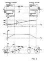
- FIGURE 2 Lengths and angles of torsional effect.
- FIGURE 3 Theory of Forces and Deformations in torsion.
- the plane (1) which coincides with the figure plane, is the regional bending plane for 2-D or plane wire frames and represents the plate of bending of a 2-D Bending Machine.
- the wire enters the machine from the left and moves to the right following the axis X-X until the Bending Head (6).
- Mechanism (2) straightens the wire.
- Mechanism (3) measures the length of the wire as it is progressed.
- Mechanism (4) applies the torsion on the wire, which is used for the formation of three-dimensional wire frames, in a way described below.
- Wire guide (5) guides the wire to the Bending Head (6), which Head bends the wire on plate (1).
- the cutter (7) is used for cutting of the ready wire frame out of the advancing wire from coil.
- Mechanism 4 The description of the mechanism for the application of the "torsion" (Mechanism 4) follows: The basic parts of the mechanism are the immovable gripper (8) and the rotating gripper (9) of the wire. In both grippers the hydraulic pistons (10) press the movable jaws (11) on immovable jaws (12) forcefully engaging the wire between them.
- the jaws are of selected length and of semi-cylindrical cross-section in such a way that no transverse normal plastic deformation to occur at the surface of the wire during the gripping action.
- the hydraulic fluid enters the pistons by the steady tube through the hole (13).
- the hydraulic fluid comes with steady tube to hole (14) and fills the cylindrical space (15) which seals with the two sealing rings (16).
- the hole (17) arrives to piston (10).
- the rotating gripper rotates by means of sprocket (18), being supported on bushing (19).
- the sprocket (18) is driven by sprocket (20) through chain (21).
- the sprocket (18) is driven by servomotor (22) and gear train speed reducer (23), the rotation angle of which is measured by rotary encoder (24).
- the rotary encoder (24) measures that way, by suitable scaling, the rotation angle of gripper (9).
- another means may be used as for example rack and pinion connection, where rack may replace sprocket (18).
- the torsional action of mechanism (4) will be described below since the operation of a 2-D Bending Machine is considered as known state-of-the-art.
- l be the total length of the jaws.
- the wire is acted gradually by the torsional moment excerted by the jaws, through its surface friction.
- l1 be the required length for total torsional moment M to to be excerted on wire.
- l1 ⁇ l the total angle of twist ⁇ o may be divided into three portions, referring to the created 3 helix of an outter generic straight line of the cylindrical surface of the wire:
Abstract
Description
- The invention refers to a method allowing wire bending machines to form three dimensional wire frames, characterised by the application of a torsion along the axis of the wire, causing a permanent plastic deformation of the wire, by twisting it beyond the yield point.
- The applicant is aware of the following cited references:

- Application No. 07/505,682 Anagnostopoulos, Dated 04/09/90.
- The general comments on these inventions are:
- There is a great variety of wire bending machines, manually operated, semi-automatic and fully automatic for the formation of two-dimensional plane wire frames. The construction, however, of machines, especially fully automatic, for the formation of three-dimensional wire frames, offers much greater difficulties.
- For the formation of three-dimensional wire frames the following methods have been used:
- (A) The Bending Head, already used for the formation of two-dimensional wire frames is movable, able to rotate about axis which coincides with the axis of feeding of straightened wire (4,735,075).
- (B) One additional Bending Head is used, which is placed after the regular Bending Head for the formation of two-dimensional wire frames and which, in the non-operational mode, is placed below the plane of two-dimensional formation of wire frames. In the operational mode, the additional Bending Head comes out of the plane, engages the wire and bends it at a plane which forms a specific angle with respect to the regular two-dimensional plane of the machine (07/505,682).
- (C) Instead of rotating the Bending Head about the axis of the wire, the rotation of the wire about its axis. This method assumes the bending of straight portions of wire and usually it is in application, in tube segments (4,662,204).
- The main problems of these methods for the formation of three-dimensional frames are the following:
- (a) The rotation of the Bending Head requires additional complicate mechanisms.
- (b) The rotation of the Bending Head sets several restrictions regarding the dimensions and the shapes of the three-dimensional frame to be formed, caused by the space requirements for the rotation of the Head.
- (c) If an additional Bending Head is to be used, the resulting disadvantage is the fact that the plane of additional bending is at certain angle with respect to the initial bending plane.
- (d) If an additional Bending Head is to be used, additional backward and forward movements of the wire to be bent are required for the application of the additional Bending Head at the exact point on the wire. In practice, the two Bending Heads are placed at a specific unaltered distance one from the other. If the wire is to be bent by the two heads, alternatively, at two points of distance less than the distance of the two bending heads, additional movements are required for the application of the Bending Heads at the exact points.
- (e) If additional Bending Head is to be used, the regular plane for the two-dimensional wire frames formation sets restriction in the shapes of 3-d frames to be formed. This plane allows the additional Bending Head to bend between 0° and 180° only, while the regular Bending Head is allowed to bend from -180° to +180°.
- (f) Finally, the additional Bending Head requires complicate mechanisms for its exit and entrance out and in the regular Bending plane.
- It offers a very simple method for the formation of three-dimensional wire frames by already existing two-dimensional, plane, Bending Machines. The method uses for the formation of three-dimensional wire frames, as additional elaboration of the wire, the "torsion" and not the "bending" of the wire already used by common three-dimensional Wire Bending Machines.
- For the formation, in the present invention, of the third dimension shape, the wire is not bent in the plane of this third dimension, either by means of an additional Bending Head or by means of rotation of already existing Bending Head, but rather after its regular two-dimensional plane bending the wire is forced to twist by an additional torsional mechanism, about its initial straight axis, at an angle of twist exceeding its yield point strain. A permanent plastic deformation is caused, in such a way that the already applied bending action to refer to plane at angle equal to twisting, remaining plastic deformation, angle. The applied torsion on the wire is of such value that the remaining after plastic deformation, angle of twist, corresponds to angle of the additional bending plane.
- The resulting advantages of the present method are the following:
- a) The mechanism for the application of torsion is very simple and does not require complicate or combined operations.
- b) It does not set any restriction in the formed three-dimensional wire frame because it is placed before the Bending Head at the straight portion of the wire.
- c) The angle of the additional bending plane may be arbitrary.
- d) No additional forward and backward movements of the wire are required for the application of the Bending Heads at the exact points.
- e) No additional mechanism is required to exit and enter the additional Bending Head from the regular bending plane. In fact, the mechanism for the application of the torsion is permanently installed below the bending plane.
- f) The predetermination of applied torsion is easy, allowing the programming of torsion as well as bending actions with resulting ability of process automation.
- A preferred embodiment is described below with references to cited figures.
- FIGURE 1: View of the plane of two-dimensional plane wire frame formation from coil, of an automatic Bending Machine with the additional mechanism of torsional action installed. This mechanism is bounded by the closed line (4).
- More specifically,
- 1. Plane of formation of two-dimensional wire frame
- 2. Straightening mechanism
- 3. Length measuring rollers
- 4. Torsional mechanism
- 5. Wire guide
- 6. Bending Head
- 7. Cutter
- 8. Immovable gripper
- 9. Rotating gripper
- 10. Pistons
- 11. Movable jaws
- 12. Steady tube
- 14. Hole
- 15. Cylindrical space
- 16. Sealing rings
- 17. Hole
- 18. Gripper rotation sprocket
- 19. Bushing
- 20. Driving sprocket
- 21. Cylinder chain
- 22. Servomotor
- 23. Gear train speed reducer
- 24. Twisting angle sensor
- FIGURE 2: Lengths and angles of torsional effect.
- FIGURE 3: Theory of Forces and Deformations in torsion.
- The plane (1) which coincides with the figure plane, is the regional bending plane for 2-D or plane wire frames and represents the plate of bending of a 2-D Bending Machine.
- The wire enters the machine from the left and moves to the right following the axis X-X until the Bending Head (6). Mechanism (2) straightens the wire. Mechanism (3) measures the length of the wire as it is progressed. Mechanism (4) applies the torsion on the wire, which is used for the formation of three-dimensional wire frames, in a way described below. Wire guide (5) guides the wire to the Bending Head (6), which Head bends the wire on plate (1). The cutter (7) is used for cutting of the ready wire frame out of the advancing wire from coil.
- For the formation of a plane frame (i.e. of Π shape) the following consecutive progressions, by mechanism (2), and bendings, by Bending Head (6), are required: progression of predetermined length- bending at specific angle - additional progression of predetermined length - additional bending at specific angle.
- If, at the end of the additional progression and before the additional bending, the wire is forced to a torsion by mechanism (4), in a direction forcing the already formed frame to move away from plate (1), then the additional bending will create a frame not on the plane of the machine but a three-dimensional one.
- The description of the mechanism for the application of the "torsion" (Mechanism 4) follows: The basic parts of the mechanism are the immovable gripper (8) and the rotating gripper (9) of the wire. In both grippers the hydraulic pistons (10) press the movable jaws (11) on immovable jaws (12) forcefully engaging the wire between them. The jaws are of selected length and of semi-cylindrical cross-section in such a way that no transverse normal plastic deformation to occur at the surface of the wire during the gripping action.
- The hydraulic fluid enters the pistons by the steady tube through the hole (13). In the rotating gripper (9) the hydraulic fluid comes with steady tube to hole (14) and fills the cylindrical space (15) which seals with the two sealing rings (16). Finally through the hole (17) it arrives to piston (10). The rotating gripper rotates by means of sprocket (18), being supported on bushing (19). The sprocket (18) is driven by sprocket (20) through chain (21).
- The sprocket (18) is driven by servomotor (22) and gear train speed reducer (23), the rotation angle of which is measured by rotary encoder (24). The rotary encoder (24) measures that way, by suitable scaling, the rotation angle of gripper (9). For the rotation of gripper (9), another means may be used as for example rack and pinion connection, where rack may replace sprocket (18). The torsional action of mechanism (4) will be described below since the operation of a 2-D Bending Machine is considered as known state-of-the-art.
- Assume that movable (11) and immovable (12) jaws compress adequately the wire between them, as a result of applied hydraulic pressure on pistons.
- Assume that the rotating gripper (9) rotates at an angle Δφo, with respect to immovable gripper (8). Then, an outter generic straight line of the cylindrical surface of the wire will receive a helical shape ABΓΔ (Fig. 2) of angle between bound radii OA and OΔ equal to Δφo.
- Let ℓ be the total length of the jaws. The wire is acted gradually by the torsional moment excerted by the jaws, through its surface friction. Let ℓ1 be the required length for total torsional moment Mto to be excerted on wire. Naturally ℓ1<<ℓ. That way, the total angle of twist Δφo may be divided into three portions, referring to the created 3 helix of an outter generic straight line of the cylindrical surface of the wire:
- * Angle of twist Δφ₁ on length ℓ1.
- * Angle of twist Δφ₂ on free length ℓ2.
- * Angle of twist Δφ₃ on length ℓ3.
- We are allowed to assume for geometrically identical jaws of equally applied hydraulic pressure that:
- Assuming perfect contact of jaws and outter surface of the wire, then applied force P on jaws (Fig.3-a) creates a uniform contact pressure P, according to the relation:

- For the applied torsional moment, if µ is the coefficient of static friction, the following relation holds:

- To determine twisting angles Δφ₁, Δφ₂, Δφ₃, the external load - external deformation relations, valid for torsion in elastic region

cannot be used since the developing stress exceeds the yield point. Actually, the developing stress in outter portions of the wire varies between the yield stress σB and ultimate stress (corresponding to rapture) σF. Assuming that equivalent shearing stress is connected to normal stress with the relation:
- The required torsional moment is given by the relation:

equation (3) for steel, heavily loaded in torsion is as follows:

- In Fig. 3-δ, the corresponding picture for the determination of the relation between twisting angle Δφ2 and length l₂ for a given required permanent deformation of wire rod:

- Taking into account that twisting angle in elastic range is negligible against the twisting angle in plastic region, and the fact that the volume of the wire rod remains constant, we have:

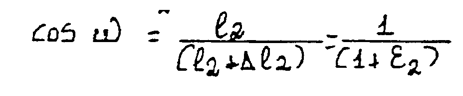
- Eliminating angle w and expressing Δφ2 in degrees We receive:
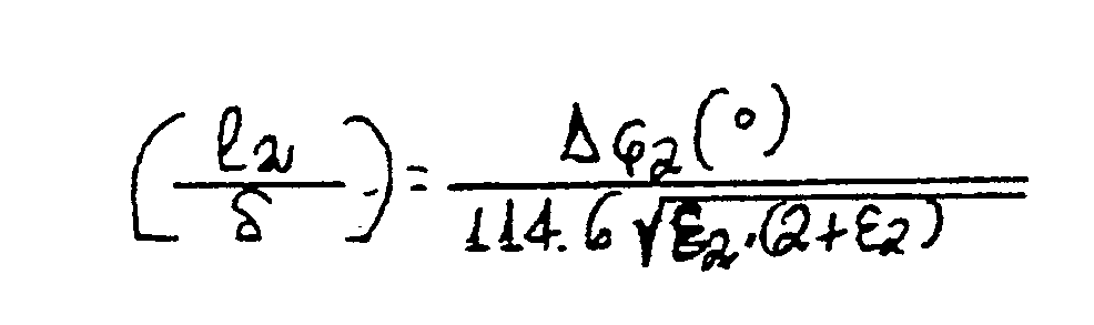
- That way, we determine the dimension l₂ in connection with diameter of wire for given twisting angle Δφ2 in degrees for desired outter normal strain ε₂ of wire.
- For example for Δφ2 = 90° and ε₂ = 10% = 0.1

Claims (5)
- Method applicable to two-dimensional wire Bending machines for extension of their operation in bending to form three dimensional wire frames, which is characterised by the application of a torsional moment along the axis of the wire and before the bending region, causing a permanent plastic deformation of the wire, by twisting it beyond the elastic region, with eventual result any bending action, already occured in the regular plane of the two-dimensional Bending Machine to be positioned at new plane which forms an angle with the regular plane equal to the remaining due to plastic deformation angle of twist.
- Method as in CLAIM 1, where the mechanism for the application of torsional moment and for twisting the wire beyond the elastic region comprises of:
Figure 1
The immovable gripper (8), the rotating gripper (9), each gripper comprising of the steady jaw (12) and the movable jaw (11), pressing the wire between with hydraulic pistons (10) to which pistons hydraulic fluid comes through steady pipe to hole (13), while in rotating gripper (9) the hydraulic fluid comes with steady pipe to hole (14), filling thereafter cylindrical space (15), sealed with two sealing rings (16) and finally arriving to piston (10) through hole (17). - Method as in CLAIM 1, where the rotating gripper (9) (Figure 1) rotates by means of sprocket (18) supported on bushing (19), which sprocket (18) is driven by sprocket (20) connected to servomotor (22) and gear train speed reducer (23), the angle of rotation of which measures rotating angle sensor (24).
- Method as in CLAIM 1, where the rotation of rotating gripper (9) may be accomplished by means of rack and pinion connection to servomotor (22).
- Method as in CLAIM 1, where the distance between the two grippers is selected from the diameter of wire δ, desired twisting angle Δφ2 in degrees (°) and maximum allowable normal strain excerted on wire ε₂ from relation:
Applications Claiming Priority (2)
| Application Number | Priority Date | Filing Date | Title |
|---|---|---|---|
| GR90100269 | 1990-04-06 | ||
| GR90010269 | 1990-04-06 |
Publications (2)
| Publication Number | Publication Date |
|---|---|
| EP0452246A2 true EP0452246A2 (en) | 1991-10-16 |
| EP0452246A3 EP0452246A3 (en) | 1992-01-15 |
Family
ID=10940112
Family Applications (1)
| Application Number | Title | Priority Date | Filing Date |
|---|---|---|---|
| EP19910600003 Withdrawn EP0452246A3 (en) | 1990-04-06 | 1991-02-28 | Method for wire bending in three dimensions |
Country Status (3)
| Country | Link |
|---|---|
| US (1) | US5170654A (en) |
| EP (1) | EP0452246A3 (en) |
| GR (1) | GR1001322B (en) |
Cited By (1)
| Publication number | Priority date | Publication date | Assignee | Title |
|---|---|---|---|---|
| US10926315B2 (en) | 2014-04-01 | 2021-02-23 | Antonios Anagnostopoulos | Systems and processes for feeding longitudinal wires or rods to mesh producing machines |
Families Citing this family (18)
| Publication number | Priority date | Publication date | Assignee | Title |
|---|---|---|---|---|
| IT1271823B (en) * | 1994-12-30 | 1997-06-09 | O M D Officina Meccanica Domas | THREAD GUIDE FOR BENDING AND TORSIONING MACHINES, WITH PERFECTED MEANS OF COMMITMENT WITH THE THREAD. |
| FR2746682B1 (en) * | 1996-03-27 | 1998-05-22 | Sipelec | METAL WIRE ARCHING MACHINE |
| US5855596A (en) * | 1996-06-25 | 1999-01-05 | International Business Machines Corporation | Modular wire band stent |
| US6193829B1 (en) | 1998-02-18 | 2001-02-27 | International Business Machines Corporation | Method and tooling for forming a stent |
| US6514063B2 (en) | 1999-01-07 | 2003-02-04 | International Business Machines Corporation | Tooling for forming a stent |
| WO2001087834A1 (en) | 2000-05-16 | 2001-11-22 | Takeda Chemical Industries, Ltd. | Melanin-concentrating hormone antagonist |
| US6612143B1 (en) * | 2001-04-13 | 2003-09-02 | Orametrix, Inc. | Robot and method for bending orthodontic archwires and other medical devices |
| US7497105B2 (en) * | 2002-06-05 | 2009-03-03 | Antonios Anagnostopoulos | Machine and method for parallel production of similar products, through straightening and bending of wires, wire rods, metal tubes or other material of prismatic cross section |
| GR1004318B (en) * | 2002-06-05 | 2003-08-28 | Αντωνης Παναγιωτη Αναγνωστοπουλος | Method and machine for simultaneous and parallel production of similar products, trough straightening and bending of wires, wire rods, metal tubes or other material of prismatic cross section. |
| GR1005272B (en) | 2005-11-15 | 2006-09-12 | Method and system for bending wires, concrete bars and materials of prismatic cross section | |
| GR1005986B (en) * | 2006-10-03 | 2008-07-10 | Method and system for the production of three-dimensional products. | |
| US8549888B2 (en) | 2008-04-04 | 2013-10-08 | Nuvasive, Inc. | System and device for designing and forming a surgical implant |
| KR200452349Y1 (en) | 2008-10-02 | 2011-02-21 | (주)하나금속 | Reform equipment of a bar form drawing item |
| IT1391412B1 (en) * | 2008-10-15 | 2011-12-23 | Schnell Spa | METHOD AND EQUIPMENT FOR REALIZING SPIRAL REINFORCEMENT FOR REINFORCED CONCRETE |
| US9156077B2 (en) * | 2012-03-29 | 2015-10-13 | L&P Property Management Company | Method of making border wire |
| RU169623U1 (en) * | 2016-04-11 | 2017-03-24 | Общество с ограниченной ответственностью "Научно-производственное предприятие "Молот" ООО "НПП "Молот" | SEMI-AUTOMATIC FOR BENDING PARTS |
| CN107570631A (en) * | 2017-09-26 | 2018-01-12 | 深圳市康振机械科技有限公司 | A kind of three-dimensional bending head and bending robot |
| CN113754332A (en) * | 2021-09-06 | 2021-12-07 | 浙江理工大学 | Three-dimensional steel fiber, manufacturing mold and method and concrete applying three-dimensional steel fiber |
Citations (3)
| Publication number | Priority date | Publication date | Assignee | Title |
|---|---|---|---|---|
| US3678723A (en) * | 1970-02-12 | 1972-07-25 | Eriez Mfg Co | T-bar twister |
| EP0032795A2 (en) * | 1980-01-21 | 1981-07-29 | Inoue Mtp Kabushiki Kaisha | Apparatus for bending elongate workpieces |
| EP0405600A1 (en) * | 1989-06-30 | 1991-01-02 | Hashimoto Forming Industry Co., Ltd. | Method and apparatus for bending manufacturing of long workpiece |
Family Cites Families (13)
| Publication number | Priority date | Publication date | Assignee | Title |
|---|---|---|---|---|
| US3202185A (en) * | 1965-08-24 | Method for bending sinuous strips | ||
| US2603269A (en) * | 1952-07-15 | Scrolling and twisting machine | ||
| US731294A (en) * | 1902-12-27 | 1903-06-16 | M W Burk | Machine for bending and twisting iron rods for making ladders, &c. |
| US1272552A (en) * | 1917-07-31 | 1918-07-16 | Robert P Spencer | Pipe-bending machine. |
| US1438322A (en) * | 1920-12-28 | 1922-12-12 | A L Smith Iron Works | Twisting machine |
| US3052277A (en) * | 1958-07-17 | 1962-09-04 | Wirth Arno H Fa | Bending machine |
| AT316268B (en) * | 1972-05-02 | 1974-07-10 | Evg Entwicklung Verwert Ges | Bending machine for rod or strip material |
| AT341860B (en) * | 1975-05-06 | 1978-03-10 | Evg Entwicklung Verwert Ges | BENDING MACHINE FOR BAR-MADE MATERIAL, ESPECIALLY FOR CONCRETE REINFORCING BAR |
| US4624121A (en) * | 1984-01-30 | 1986-11-25 | Hashimoto Forming Industry Co., Ltd. | Method of, and apparatus for producing multi-dimensionally bent elongate articles |
| DE3415006A1 (en) * | 1984-04-19 | 1985-11-07 | Helge Dr. 8000 München Fischer-Brandies | DENTAL PROCESS AND DEVICE FOR BENDING AND TURNING A WIRE PIECE |
| IT8453880V0 (en) * | 1984-10-02 | 1984-10-02 | Mauro Meliga | BENDING MACHINE FOR PROFILED AND SIMILAR TUBES |
| US4662204A (en) * | 1985-01-17 | 1987-05-05 | Usui Kokusai Sangyo Kabushiki Kaisha | Apparatus for automatically bending metallic tubes |
| JPH089063B2 (en) * | 1985-10-21 | 1996-01-31 | 臼井国際産業株式会社 | Bending unit device in automatic pipe bender |
-
1990
- 1990-04-06 GR GR900100269A patent/GR1001322B/en unknown
-
1991
- 1991-02-28 EP EP19910600003 patent/EP0452246A3/en not_active Withdrawn
- 1991-04-04 US US07/680,435 patent/US5170654A/en not_active Expired - Lifetime
Patent Citations (3)
| Publication number | Priority date | Publication date | Assignee | Title |
|---|---|---|---|---|
| US3678723A (en) * | 1970-02-12 | 1972-07-25 | Eriez Mfg Co | T-bar twister |
| EP0032795A2 (en) * | 1980-01-21 | 1981-07-29 | Inoue Mtp Kabushiki Kaisha | Apparatus for bending elongate workpieces |
| EP0405600A1 (en) * | 1989-06-30 | 1991-01-02 | Hashimoto Forming Industry Co., Ltd. | Method and apparatus for bending manufacturing of long workpiece |
Cited By (1)
| Publication number | Priority date | Publication date | Assignee | Title |
|---|---|---|---|---|
| US10926315B2 (en) | 2014-04-01 | 2021-02-23 | Antonios Anagnostopoulos | Systems and processes for feeding longitudinal wires or rods to mesh producing machines |
Also Published As
| Publication number | Publication date |
|---|---|
| GR900100269A (en) | 1992-07-30 |
| EP0452246A3 (en) | 1992-01-15 |
| GR1001322B (en) | 1993-08-31 |
| US5170654A (en) | 1992-12-15 |
Similar Documents
| Publication | Publication Date | Title |
|---|---|---|
| EP0452246A2 (en) | Method for wire bending in three dimensions | |
| US5765426A (en) | Pipe bending apparatus | |
| US4558577A (en) | Roll-forming machine for making articles having cross-sectional configurations varying lengthwise | |
| US4843859A (en) | Pipe bender | |
| CA2245353C (en) | Universal machine for bending pipes or section bars to both fixed and variable curvatures | |
| US4888971A (en) | Pipe bending machine | |
| CA2007985A1 (en) | Movable shears upstream of a bending assembly and method to bend the trailing end of bars | |
| US4538436A (en) | Pipe bending machine with bending mandrel | |
| EP0379043B1 (en) | Drawing unit downstream of a bending assembly and method to bend the trailing end of bars | |
| KR100818840B1 (en) | Apparatus for bending and working long materials | |
| US4232813A (en) | Method and apparatus for making bent pipe | |
| US4479373A (en) | Tube bending assembly, particularly for thin wall and small and medium diameter metal tubes | |
| US3657911A (en) | Bending machine | |
| EP3664946A1 (en) | Machine and method for bending oblong elements, preferably metal, such as bars, rod, section bars or suchlike | |
| US5351515A (en) | Apparatus and method for reducing the diameter of a cylindrical workpiece | |
| SU770608A1 (en) | Feeding arrangement to tube bending machine | |
| US3672410A (en) | Apparatus for forming retaining members | |
| US3762196A (en) | Pipe bending machine | |
| EP0379028A1 (en) | Orthogonal adjustment unit and method for orthogonal adjustment of straightened bars | |
| ITUA20164496A1 (en) | METHOD OF LINEAR DRAWING OF WOVEN METALLIC THREAD WITH THE USE OF SATELLITE ROLLER SCREWS OR SPIRAL BALL RECIRCULATION APPLIED TO A LINEAR DETACHING MACHINE | |
| JPH0238049B2 (en) | ||
| US4079616A (en) | Draw bench for producing cylindrical tubular items by drawing | |
| RU2614975C1 (en) | Pipe bending method and machine for method performing | |
| EP3620241B1 (en) | Machine for the working of tubes provided with a device for detecting any slippage of the tube being worked | |
| US3395846A (en) | Machine for bending sheet metal |
Legal Events
| Date | Code | Title | Description |
|---|---|---|---|
| PUAI | Public reference made under article 153(3) epc to a published international application that has entered the european phase |
Free format text: ORIGINAL CODE: 0009012 |
|
| AK | Designated contracting states |
Kind code of ref document: A2 Designated state(s): AT DE FR GB IT |
|
| PUAL | Search report despatched |
Free format text: ORIGINAL CODE: 0009013 |
|
| AK | Designated contracting states |
Kind code of ref document: A3 Designated state(s): AT DE FR GB IT |
|
| 17P | Request for examination filed |
Effective date: 19920619 |
|
| D17P | Request for examination filed (deleted) | ||
| R17P | Request for examination filed (corrected) |
Effective date: 19920619 |
|
| 17Q | First examination report despatched |
Effective date: 19940217 |
|
| STAA | Information on the status of an ep patent application or granted ep patent |
Free format text: STATUS: THE APPLICATION IS DEEMED TO BE WITHDRAWN |
|
| 18D | Application deemed to be withdrawn |
Effective date: 19950829 |