EP0449801A2 - Apparatus for bending hollow frames for isolating glass - Google Patents
Apparatus for bending hollow frames for isolating glass Download PDFInfo
- Publication number
- EP0449801A2 EP0449801A2 EP91890054A EP91890054A EP0449801A2 EP 0449801 A2 EP0449801 A2 EP 0449801A2 EP 91890054 A EP91890054 A EP 91890054A EP 91890054 A EP91890054 A EP 91890054A EP 0449801 A2 EP0449801 A2 EP 0449801A2
- Authority
- EP
- European Patent Office
- Prior art keywords
- hollow profile
- gripper
- bending
- carriage
- slide
- Prior art date
- Legal status (The legal status is an assumption and is not a legal conclusion. Google has not performed a legal analysis and makes no representation as to the accuracy of the status listed.)
- Granted
Links
Images

Classifications
-
- B—PERFORMING OPERATIONS; TRANSPORTING
- B21—MECHANICAL METAL-WORKING WITHOUT ESSENTIALLY REMOVING MATERIAL; PUNCHING METAL
- B21D—WORKING OR PROCESSING OF SHEET METAL OR METAL TUBES, RODS OR PROFILES WITHOUT ESSENTIALLY REMOVING MATERIAL; PUNCHING METAL
- B21D53/00—Making other particular articles
- B21D53/74—Making other particular articles frames for openings, e.g. for windows, doors, handbags
-
- E—FIXED CONSTRUCTIONS
- E06—DOORS, WINDOWS, SHUTTERS, OR ROLLER BLINDS IN GENERAL; LADDERS
- E06B—FIXED OR MOVABLE CLOSURES FOR OPENINGS IN BUILDINGS, VEHICLES, FENCES OR LIKE ENCLOSURES IN GENERAL, e.g. DOORS, WINDOWS, BLINDS, GATES
- E06B3/00—Window sashes, door leaves, or like elements for closing wall or like openings; Layout of fixed or moving closures, e.g. windows in wall or like openings; Features of rigidly-mounted outer frames relating to the mounting of wing frames
- E06B3/66—Units comprising two or more parallel glass or like panes permanently secured together
- E06B3/673—Assembling the units
- E06B3/67304—Preparing rigid spacer members before assembly
- E06B3/67308—Making spacer frames, e.g. by bending or assembling straight sections
- E06B3/67313—Making spacer frames, e.g. by bending or assembling straight sections by bending
-
- E—FIXED CONSTRUCTIONS
- E06—DOORS, WINDOWS, SHUTTERS, OR ROLLER BLINDS IN GENERAL; LADDERS
- E06B—FIXED OR MOVABLE CLOSURES FOR OPENINGS IN BUILDINGS, VEHICLES, FENCES OR LIKE ENCLOSURES IN GENERAL, e.g. DOORS, WINDOWS, BLINDS, GATES
- E06B3/00—Window sashes, door leaves, or like elements for closing wall or like openings; Layout of fixed or moving closures, e.g. windows in wall or like openings; Features of rigidly-mounted outer frames relating to the mounting of wing frames
- E06B3/66—Units comprising two or more parallel glass or like panes permanently secured together
- E06B3/673—Assembling the units
- E06B2003/67395—Non-planar units or of curvilinear outline, e.g. for vehicles
Definitions
- the invention relates to a device for bending hollow profile strips to form spacer frames for insulating glass panes with a bending device and a conveyor for transporting the hollow profile strip.
- Such devices are known for example from DE-GM 87 05 796.4 or DE-OS 32 21 986.
- the length of the profile bar (hollow profile bar) projecting beyond the bending point must be determined so that the spacer frame is obtained with the desired dimensions.
- the known bending devices for producing a spacer for insulating glass determine the length of the profile bar by measuring the distance via incremental encoders.
- the profiled rod is moved by transport rollers resting against it on both sides, at least one of which is driven.
- An impeller encoder wheel
- the encoder wheel which runs along the outer profile wall, detects the extent of the advance of the hollow profile bar.
- CH-PS 638 273 From CH-PS 638 273 a device for pressing insulating bars into metal profiles to be joined together to form a composite profile is known.
- a longitudinal movement of the insulating rod is just as little caused by the jaws as in CH-PS 638 273 a movement of the jaws 26 applied to the insulating rod in the longitudinal direction is mentioned.
- a pair of rollers is provided for moving the hollow profile strip.
- the rollers cannot be moved in the longitudinal direction of the hollow profile bar.
- transport rollers which are not movably mounted in the machine frame in the conveying direction, also serve to advance the hollow profile strip to be moved.
- the object of the invention is to create a device with which the length of the profile, i.e. the extent of the advance of the hollow profile strip, can be measured precisely and without tolerances.
- a Gripper is provided, which can be fixed on the hollow profile bar and which is displaceable parallel to the conveyor by a preselectable distance.
- the hollow profile strip (profile bar) to be bent to the spacer frame is advanced by the gripper exactly before each bending operation by the distance which corresponds to the length of the respective leg of the spacer frame. If the length of the leg is greater than the maximum stroke of the gripper, the profile bar is advanced in two or at most more than two steps.
- the procedure can be such that the first stroke (or the first strokes) correspond to a predetermined length (e.g. the maximum stroke) and the last stroke is adapted to the length of the frame leg.
- a structurally simple embodiment of the device according to the invention is characterized in that the gripper is provided on a carriage which is displaceable on a guide running parallel to the conveying device.
- the extent of the movement of the slide for the gripper and thus the advance of the hollow profile bar can be determined particularly precisely and without great effort if it is provided that the drive motor for the slide has a displacement measuring device, e.g. an incremental encoder is assigned.
- the carriage is coupled to an endless toothed belt driven by the drive motor.
- the drive motor is mounted on the slide and has a pinion which meshes with a toothed rack which is fixedly mounted in the device.
- the method of operation is simplified if a stop which can be lowered under the conveying device is provided at the bending point.
- a hollow profile strip 3 is on a conveyor 4, which is arranged at the lower end of a support wall 10 and is, for example, an endless conveyor belt or a simple slideway, up to a stop 7 in the region of a bending point, consisting of a bending abutment 8 and a bending lever 9, which for the Bending the hollow profile bar 3 is pivoted, transported.
- the device can also have, for example, the structure known from DE-GM 87 05 796 and have a support finger which can be adjusted up and down in the support wall 10 and which extends through the support wall 10, as is also the case in the known device according to DE-GM 87 05 796 is provided.
- the hollow profile bar 3 is from the transport device 4 advanced at the lower edge of the support wall 10 to the end stop 7.
- the hollow profile strip 3 is thus in a "zero" position without tolerance.
- the jaws of the gripper 2 mounted on the slide 1 grip the hollow profile bar 3 in this position.
- the end stop 7 is sunk into the conveyor track 4 and the carriage 1 with the hollow profile bar 3 clamped by the gripper 2 now moves in the direction of the bending lever 9 exactly by the distance that a process computer specifies and that corresponds to the length of the frame leg.
- the bending lever 9 bends the section 3 'projecting beyond the carriage 1' of the hollow profile strip 3, which moves along the backward inclined support wall 10 according to the angle predetermined by a process computer becomes.
- the exact measurement of the distance traveled by the carriage 1 is determined by an incremental encoder 6 or the extent of the movement of the carriage 1 and thus the extent of the advance of the hollow profile strip 3 is controlled by the latter.
- the incremental encoder 6 is mounted on the drive motor 5 or at another point on the movement path 4 of the carriage 1.
- the carriage 1 is driven by an endless toothed belt and is guided on a guide running parallel to the conveyor track 4.
- the engagement of the toothed belt in the drive gear of the drive motor 5 is exact and free of play, so that an incremental encoder 6 mounted directly on the motor-gearbox unit can also accurately register the distance traveled by the slide 1.
- the effective distance to be traveled by the carriage 1 corresponds to the length of the section 3 'of the hollow profile bar 3, which the process computer determines and the length of a leg of the hollow profile bar 3 to be produced by the bending processes Spacer frame corresponds.
- the drive motor 5 does not need to be fixedly mounted on the bending table 10, but can also be arranged on the slide 1.
- the drive gear of the drive motor 5 (geared motor) then engages in the toothed rack fastened to the guide 4, it being possible for an incremental encoder 6 to also be mounted on the drive motor 5 or on the slide 1.
- the gripper 2 mounted on the slide 1 detaches from the hollow profile bar 3.
- the slide 1 then moves back at high speed into its starting position (reference point), and the gripper 2 is gripped the hollow profile strip 3 again frictionally.
- the carriage 1 can again move in the direction of the bending lever 9 exactly by the distance specified by the process computer and move the hollow profile strip 3 accordingly.
- the conveyor track 4 can be a simple slideway.
- At least one gripper 2 is mounted on the movable carriage 1, which is driven in a slip-free manner by means of a drive means 5 (geared motor), which grips the hollow profile bar 3 in a friction-locked manner.
- the unit slide 1 and gripper 2 transports the hollow profile strip 3 in the direction of the bending lever 9.
- the bending lever 9 presses the section 3 'of the hollow profile bar 3 against the bending abutment 8 (bending beam) as high as from the process computer is determined for the angle in the corner of the spacer frame that is to be bent.
- FIG. 3 A particularly favorable embodiment of a gripper 2, which ensures the necessary frictional engagement for the precise advancement of the hollow profile strip 3, is shown in FIG. 3.
- the movable jaw 12 can be pivoted behind the support wall 10 of the device so that it does not hinder the removal of a finished bent spacer frame.
Abstract
Description
Die Erfindung betrifft eine Vorrichtung zum Biegen von Hohlprofilleisten zu Abstandhalterrahmen für Isolierglasscheiben mit einer Biegeeinrichtung und einer Fördereinrichtung für den Transport der Hohlprofilleiste.The invention relates to a device for bending hollow profile strips to form spacer frames for insulating glass panes with a bending device and a conveyor for transporting the hollow profile strip.
Solche Vorrichtungen sind beispielsweise aus dem DE-GM 87 05 796.4 oder der DE-OS 32 21 986 bekannt. Bei diesen bekannten Vorrichtungen muß die über die Biegestelle überstehende Länge des Profilstabes (Hohlprofilleiste) bestimmt werden, damit der Abstandhalterrahmen mit den gewünschten Abmessungen erhalten wird.Such devices are known for example from DE-GM 87 05 796.4 or DE-OS 32 21 986. In these known devices, the length of the profile bar (hollow profile bar) projecting beyond the bending point must be determined so that the spacer frame is obtained with the desired dimensions.
Die bekannten Biegevorrichtungen zum Herstellen eines Abstandhalters für Isolierglas bestimmen die Länge des Profilstabes durch Wegmessung über Inkrementalgeber.The known bending devices for producing a spacer for insulating glass determine the length of the profile bar by measuring the distance via incremental encoders.
In der Regel wird der Profilstab von an ihm beidseitig anliegenden Transportrollen bewegt, von welchen wenigstens eine angetrieben ist. Auf der äußeren Wand des so transportierten Profilstabes rollt ein Laufrad (Geberrad) ab, das über die Achse oder einen sonstigen Antrieb kraftschlüssig mit einem Inkrementalgeber verbunden ist.As a rule, the profiled rod is moved by transport rollers resting against it on both sides, at least one of which is driven. An impeller (encoder wheel) rolls on the outer wall of the profile rod thus transported, which is non-positively connected to an incremental encoder via the axis or another drive.
Das Geberrad, das an der äußeren Profilwandung entlang läuft, erfaßt das Ausmaß des Vorschubes der Hohlprofilleiste.The encoder wheel, which runs along the outer profile wall, detects the extent of the advance of the hollow profile bar.
Ein Nachteil bei diesen Vorrichtungen ist darin zu sehen, daß der Reibungsschluß zwischen dem Geberrad und dem Profilstab ungleichmäßig ist und so einen mehr oder weniger großen Schlupf zur Folge hat. Verschieden beschaffene Materialoberflächen des Profilstabes, glatt oder rauh, oder auch Rückstände von Staub oder Metallspänen, verursachen unweigerlich eine Fehlmessung des Inkrementalgebers, dies vor allem, wenn der Profilstab während der Meßbewegung angehalten wird oder zum Geberrad nur einfährt.A disadvantage of these devices can be seen in the fact that the frictional engagement between the encoder wheel and the profile rod is non-uniform and thus results in a more or less large slip. Different types Material surfaces of the profile bar, smooth or rough, or even residues of dust or metal chips, inevitably cause an incorrect measurement of the incremental encoder, especially if the profile bar is stopped during the measuring movement or only retracts to the encoder wheel.
Aus der CH-PS 638 273 ist eine Vorrichtung zum Einpressen von Isolierstäben in miteinander zu einem Verbundprofil zu verbindende Metallprofile bekannt. Die in der CH-PS 638 273 beschriebenen, an einen Isolierstab anlegbaren Backen dienen zum Festhalten des Isolierstabes, bevor auf diesen Metallprofile aufgeschoben werden sollen. Die Bakken richten den Isolierstab so aus, daß die Metallprofile aufgeschoben werden können. Eine Längsbewegung des Isolierstabes wird durch die Backen ebensowenig bewirkt wie in der CH-PS 638 273 eine Bewegung der an den Isolierstab angelegten Backen 26 in Längsrichtung erwähnt wird.From CH-PS 638 273 a device for pressing insulating bars into metal profiles to be joined together to form a composite profile is known. The jaws described in CH-PS 638 273, which can be placed on an insulating rod, serve to hold the insulating rod in place before metal profiles are to be pushed onto it. The Bakken align the insulating rod so that the metal profiles can be pushed on. A longitudinal movement of the insulating rod is just as little caused by the jaws as in CH-PS 638 273 a movement of the jaws 26 applied to the insulating rod in the longitudinal direction is mentioned.
Bei der aus dem DE-GM 87 05 796.4 bekannten Biegevorrichtung ist zum Verschieben der Hohlprofilleiste ein Rollenpaar vorgesehen. Die Rollen sind in Längsrichtung der Hohlprofilleiste nicht verschiebbar.In the bending device known from DE-GM 87 05 796.4, a pair of rollers is provided for moving the hollow profile strip. The rollers cannot be moved in the longitudinal direction of the hollow profile bar.
Bei der aus der DE-OS 32 21 986 bekannten Biegevorrichtung dienen ebenfalls Transportrollen, die im Maschinengestell in Förderrichtung nicht beweglich montiert sind, für den Vorschub der zu bewegenden Hohlprofilleiste.In the bending device known from DE-OS 32 21 986, transport rollers, which are not movably mounted in the machine frame in the conveying direction, also serve to advance the hollow profile strip to be moved.
Aufgrund der Nachteile der bekannten Meßeinrichtungen liegt der Erfindung die Aufgabe zugrunde, eine Vorrichtung zu schaffen, mit der beim Profiltransport in eine Biegevorrichtung die gefahrene Länge des Profils, d.h. das Ausmaß des Vorschubes der Hohlprofilleiste, genau und ohne Toleranzen meßbar ist.Because of the disadvantages of the known measuring devices, the object of the invention is to create a device with which the length of the profile, i.e. the extent of the advance of the hollow profile strip, can be measured precisely and without tolerances.
Gelöst wird diese Aufgabe erfindungsgemäß mit einer Vorrichtung, die sich dadurch auszeichnet, daß ein Greifer vorgesehen ist, der an der Hohlprofilleiste festlegbar ist und der um eine vorwählbare Strecke parallel zur Fördereinrichtung verschiebbar ist.This object is achieved according to the invention with a device which is characterized in that a Gripper is provided, which can be fixed on the hollow profile bar and which is displaceable parallel to the conveyor by a preselectable distance.
Mit der erfindungsgemäßen Vorrichtung wird die zum Abstandhalterrahmen zu biegende Hohlprofilleiste (Profilstab) vor jedem Biegevorgang vom Greifer genau um die Strecke vorgeschoben, die der Länge des jeweiligen Schenkels des Abstandhalterrahmens entspricht. Falls die Länge des Schenkels größer ist als der maximale Hub des Greifers, wird die Profilleiste in zwei oder allenfalls mehr als zwei Schritten vorgeschoben. Dabei kann so vorgegangen werden, daß der erste Hub (oder die ersten Hübe) einer vorgegebenen Länge (z.B. dem maximalen Hub) entsprechen und der letzte Hub an die Länge des Rahmenschenkels angepaßt wird.With the device according to the invention, the hollow profile strip (profile bar) to be bent to the spacer frame is advanced by the gripper exactly before each bending operation by the distance which corresponds to the length of the respective leg of the spacer frame. If the length of the leg is greater than the maximum stroke of the gripper, the profile bar is advanced in two or at most more than two steps. The procedure can be such that the first stroke (or the first strokes) correspond to a predetermined length (e.g. the maximum stroke) and the last stroke is adapted to the length of the frame leg.
Eine konstruktiv einfache Ausführungsform der erfindungsgemäßen Vorrichtung zeichnet sich dadurch aus, daß der Greifer an einem Schlitten vorgesehen ist, der auf einer parallel zur Fördereinrichtung verlaufenden Führung verschiebbar ist.A structurally simple embodiment of the device according to the invention is characterized in that the gripper is provided on a carriage which is displaceable on a guide running parallel to the conveying device.
Das Ausmaß der Bewegung des Schlittens für den Greifer und damit des Vorschubes der Hohlprofilleiste ist besonders genau und ohne großen Aufwand feststellbar, wenn vorgesehen ist, daß dem Antriebsmotor für den Schlitten eine Wegmeßeinrichtung, z.B. ein Inkrementalgeber, zugeordnet ist.The extent of the movement of the slide for the gripper and thus the advance of the hollow profile bar can be determined particularly precisely and without great effort if it is provided that the drive motor for the slide has a displacement measuring device, e.g. an incremental encoder is assigned.
In der Praxis ist erfindungsgemäß bevorzugt, daß der Schlitten mit einem vom Antriebsmotor angetriebenen Endlos-Zahnriemen gekuppelt ist. So wird ohne weiteres ein schlupffreier Antrieb gewährleistet. Alternativ kann vorgesehen sein, daß der Antriebsmotor am Schlitten montiert ist und ein Ritzel besitzt, das mit einer in der Vorrichtung ortsfest montierten Zahnstange kämmt.In practice it is preferred according to the invention that the carriage is coupled to an endless toothed belt driven by the drive motor. This guarantees a slip-free drive without further ado. Alternatively, it can be provided that the drive motor is mounted on the slide and has a pinion which meshes with a toothed rack which is fixedly mounted in the device.
Die Arbeitsweise vereinfacht sich, wenn an der Biegestelle ein unter die Fördereinrichtung versenkbarer Anschlag vorgesehen ist.The method of operation is simplified if a stop which can be lowered under the conveying device is provided at the bending point.
Weitere Einzelheiten und Merkmale der Erfindung ergeben sich aus der nachstehenden Beschreibung einer in den Zeichnungen schematisch gezeigten Ausführungsform. Es zeigt:
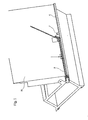
- Fig. 1 eine Vorrichtung zum Biegen von Hohlprofilleisten zu Abstandhalterrahmen,
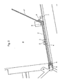
- Fig. 2 die Vorrichtung aus Fig. 1 in vergrößertem Maßstab und
- Fig. 3 eine Ausführungsform einer Vorschubvorrichtung.
- 1 shows a device for bending hollow profile strips to form spacer frames,
- Fig. 2 shows the device of Fig. 1 on an enlarged scale and
- Fig. 3 shows an embodiment of a feed device.
Eine Hohlprofilleiste 3 wird auf einer Fördervorrichtung 4, die am unteren Ende einer Stützwand 10 angeordnet und beispielsweise ein Endlosfördergurt oder eine einfache Gleitbahn ist, bis zu einem Anschlag 7 im Bereich einer Biegestelle, bestehend aus einem Biegewiderlager 8 und einem Biegehebel 9, der für das Biegen der Hohlprofilleiste 3 verschwenkbar ist, transportiert.A
Der über die Biegestelle 8/9 - wie weiter unten beschrieben - hinaus transportierte Abschnitt 3′ der Hohlprofilleiste 3 wird an der Stützwand 10 anliegend von dem Biegehebel 9 um ein Widerlager 8 herum gebogen.The on the
Die Vorrichtung kann im übrigen beispielsweise den aus dem DE-GM 87 05 796 bekannten Aufbau besitzen und einen in der Stützwand 10 auf und ab verstellbaren, die Stützwand 10 durchgreifenden Stützfinger aufweisen, wie er auch in der bekannten Vorrichtung nach dem DE-GM 87 05 796 vorgesehen ist.The device can also have, for example, the structure known from DE-GM 87 05 796 and have a support finger which can be adjusted up and down in the
Die Hohlprofilleiste 3 wird von der Transportvorrichtung 4 am unteren Rand der Stützwand 10 bis zum Endanschlag 7 vorgeschoben. Die Hohlprofilleiste 3 befindet sich damit toleranzfrei in einer "Null"-Position. Nun erfassen die am Schlitten 1 montierten Backen des Greifers 2 die Hohlprofilleiste 3 in dieser Lage. Der Endanschlag 7 wird in die Förderbahn 4 versenkt und der Schlitten 1 mit der vom Greifer 2 festgeklemmten Hohlprofilleiste 3 fährt nun in Richtung des Biegehebels 9 genau um jene Strecke vor, die ein Prozeßrechner vorgibt und die der Länge des Rahmenschenkels entspricht. Erreicht der Schlitten 1 den vorgegebenen und effektiv gemessenen Endpunkt seiner Bewegung, biegt der Biegehebel 9 den über den Schlitten 1 überstehenden Abschnitt 3′ der Hohlprofilleiste 3 ab, wobei dieser entlang der nach rückwärts geneigten Stützwand 10 nach dem von einem Prozeßrechner vorgegebenen Winkel nach oben bewegt wird.The
Die genaue Messung der vom Schlitten 1 gefahrenen Wegstrecke ermittelt ein Inkrementalgeber 6 bzw. wird das Ausmaß der Bewegung des Schlittens 1 und damit das Ausmaß des Vorschubes der Hohlprofilleiste 3 über diesen gesteuert. Der Inkrementalgeber 6 ist am Antriebsmotor 5 oder an einer anderen Stelle der Bewegungsbahn 4 des Schlittens 1 montiert.The exact measurement of the distance traveled by the
Der Schlitten 1 wird von einem Endlos-Zahnriemen angetrieben, und ist auf einer parallel zur Förderbahn 4 verlaufenden Führung geführt.The
Der Eingriff des Zahnriemens in das Antriebszahnrad des Antriebsmotors 5 (Getriebemotor) ist exakt und spielfrei, so daß auch ein unmittelbar an der Motor-Getriebe-Einheit montierter Inkrementalgeber 6 die gefahrene Wegstrecke des Schlittens 1 genau registrieren kann. Die efffektiv zu fahrende Strecke des Schlittens 1 entspricht der Länge des Abschnittes 3′ der Hohlprofilleiste 3, die der Prozeßrechner bestimmt und die der Länge eines Schenkels des durch die Biegevorgänge aus der Hohlprofilleiste 3 herzustellenden Abstandhalterrahmen entspricht.The engagement of the toothed belt in the drive gear of the drive motor 5 (geared motor) is exact and free of play, so that an
Vorteilhaft für den Antrieb des Schlittens 1 ist auch die Anwendung einer Zahnstange, die an der Transportbahn des Schlittens 1 montiert ist. Bei dieser alternativ anwendbaren Einrichtung braucht der Antriebsmotor 5 am Biegetisch 10 nicht fix montiert sein, sondern kann auch am Schlitten 1 angeordnet sein. Das Antriebszahnrad des Antriebsmotors 5 (Getriebemotor) greift dann in die an der Führung 4 befestigte Zahnstange ein, wobei ein Inkrementalgeber 6 ebenfalls am Antriebsmotor 5 oder am Schlitten 1 montiert sein kann.The use of a toothed rack, which is mounted on the transport path of the
Während der Biegehebel 9 den Abschnitt 3′ der Hohlprofilleiste 3 nach oben biegt, löst sich der am Schlitten 1 montierte Greifer 2 von der Hohlprofilleiste 3. Der Schlitten 1 fährt dann mit hoher Geschwindigkeit in seine Ausgangslage (Referenzpunkt) zurück, und der Greifer 2 erfaßt die Hohlprofilleiste 3 wieder reibungsschlüssig. Darauf kann der Schlitten 1, nachdem der Biegehebel 9 zurückgeschwenkt wurde, wieder in Richtung Biegehebel 9 genau um die vom Prozeßrechner vorgegebene Wegstrecke verfahren und die Hohlprofilleiste 3 entsprechend verschieben.While the bending lever 9 bends the section 3 'of the
Wenn die Hohlprofilleiste 3 in die Vorrichtung von einer dieser vorgeschalteten Zuführeinrichtung bis zum Anschlag 7 zugeführt wird, kann die Förderbahn 4 eine einfache Gleitbahn sein.If the
Für die Erfindung ist wenigstens eines der folgenden Merkmale wesentlich:At least one of the following features is essential for the invention:
Parallel zur Profiltransportebene der nach rückwärts geneigten Stützwand 10 befindet sich in der unteren horizontalen Ebene eine Führung, über welche eine Transporteinrichtung verfährt, wobei die gefahrene Strecke erfaßt wird.Parallel to the profile transport plane of the backward
Am verfahrbaren Schlitten 1, der schlupffrei über ein Antriebsmittel 5 (Getriebemotor) angetrieben wird, ist wenigstens ein Greifer 2 montiert, der die Hohlprofilleiste 3 reibungsschlüssig erfaßt. Die Einheit Schlitten 1 und Greifer 2 transportiert die Hohlprofilleiste 3 in Richtung Biegehebel 9. Ein Inkrementalgeber 6, der am Antriebsmotor 5 oder am Transportschlitten 1 montiert ist, greift formschlüssig in einen Transportzahnriemen oder eine Zahnstange ein und erfaßt die vom Schlitten 1 effektiv gefahrene Strecke, die ein Prozeßrechner vorgibt.At least one
Nach Erreichen des Endabschaltpunktes, d.h. wenn die Hohlprofilleiste 3 der Länge des Rahmenschenkels entsprechend vom Schlitten 1, der mit seinem Greifer 2 die Hohlprofilleiste 3 festhält, vorgeschoben wurde, drückt der Biegehebel 9 den Abschnitt 3′ der Hohlprofilleiste 3 gegen das Biegewiderlager 8 (Biegewange) soweit hoch, als vom Prozeßrechner für den Winkel in der gerade zu biegenden Ecke des herzustellenden Abstandhalterrahmens bestimmt wird.After reaching the end stop point, i.e. when the
Während der Biegehebel 9 den Abschnitt 3′ der Hohlprofilleiste 3 um das Biegewiderlager 8 um den vorgegebenen Winkel, entlang der nach hinten geneigten Stützwand 10 nach oben drückt, öffnet sich der Greifer 2 und der Schlitten 1 fährt zurück in die Ausgangslage, wonach sich der Greifer 2 wieder schließt und die Hohlprofilleiste 3 reibungsschlüssig festhält. Hierauf fährt der Schlitten 1 wieder entsprechend der vorgegebenen Weglänge in Richtung Biegestelle 8/9 vor und die nächste Ecke kann gebogen werden.While the bending lever 9 section 3 'of the
Eine besonders günstige Ausführungsform eines Greifers 2, der den nötigen Reibungsschluß für den genauen Vorschub der Hohlprofilleiste 3 sicherstellt, ist in Fig. 3 gezeigt. Es ist ersichtlich, daß die untere Backe 16 mit einem in Förderrichtung auf wenigstens einer Führungsschiene (nicht gezeigt) geführten Schlitten 11 starr verbunden ist, wogegen die obere Backe 12 über Parallelogrammlenker 13 durch einen Druckmittelmotor 14 von der Backe 16 weg schwenkbar ist. Die bewegliche Backe 12 kann hinter die Stützwand 10 der Vorrichtung verschwenkt werden, so daß sie den Abtransport eines fertig gebogenen Abstandhalterrahmens nicht behindert.A particularly favorable embodiment of a
Claims (10)
Applications Claiming Priority (4)
| Application Number | Priority Date | Filing Date | Title |
|---|---|---|---|
| AT742/90 | 1990-03-30 | ||
| AT74290A AT398395B (en) | 1990-03-30 | 1990-03-30 | DEVICE FOR BENDING HOLLOW PROFILE BARS TO SPACER FRAME FOR INSULATING GLASS |
| AT1840/90 | 1990-09-10 | ||
| AT184090A AT397775B (en) | 1990-09-10 | 1990-09-10 | Bending device for holder profile rails - incorporates displaceable grab for rails |
Publications (3)
| Publication Number | Publication Date |
|---|---|
| EP0449801A2 true EP0449801A2 (en) | 1991-10-02 |
| EP0449801A3 EP0449801A3 (en) | 1991-11-06 |
| EP0449801B1 EP0449801B1 (en) | 1993-11-18 |
Family
ID=25593786
Family Applications (1)
| Application Number | Title | Priority Date | Filing Date |
|---|---|---|---|
| EP91890054A Expired - Lifetime EP0449801B1 (en) | 1990-03-30 | 1991-03-21 | Apparatus for bending hollow frames for isolating glass |
Country Status (7)
| Country | Link |
|---|---|
| US (1) | US5181412A (en) |
| EP (1) | EP0449801B1 (en) |
| JP (1) | JPH0724890B2 (en) |
| DE (2) | DE59100592D1 (en) |
| DK (1) | DK0449801T3 (en) |
| ES (1) | ES2046883T3 (en) |
| NO (1) | NO179683C (en) |
Cited By (2)
| Publication number | Priority date | Publication date | Assignee | Title |
|---|---|---|---|---|
| WO2020070245A1 (en) | 2018-10-04 | 2020-04-09 | Lisec Austria Gmbh | Method and device for producing spacer frames for insulating glass |
| CN111633081A (en) * | 2020-06-11 | 2020-09-08 | 郑文豪 | Large steel bending equipment and bending process |
Families Citing this family (9)
| Publication number | Priority date | Publication date | Assignee | Title |
|---|---|---|---|---|
| ES2049542T5 (en) * | 1990-06-07 | 1999-06-01 | Peter Lisec | PROCEDURE AND DEVICE FOR BENDING PROFILED HOLLOW TAPES IN SEPARATION FRAMES FOR INSULATED GLASS SHEETS. |
| ES2096268T3 (en) * | 1992-07-16 | 1997-03-01 | Peter Lisec | DEVICE FOR THE MANUFACTURE OF DISTANCING FRAMES FOR INSULATING CRYSTALS FROM HOLLOW PROFILE SLATS. |
| US6591988B2 (en) * | 2001-01-19 | 2003-07-15 | Cardinal Glass Industries, Inc. | Material handling for the insulating glass industry |
| US6739101B2 (en) * | 2001-01-19 | 2004-05-25 | Cardinal Ig Company | Methods and apparatus for manufacturing muntin bar assemblies |
| WO2003059790A1 (en) * | 2002-01-15 | 2003-07-24 | Cardinal Ig Company | Method and apparatus for handling fragile bars |
| GB2390566A (en) * | 2002-07-09 | 2004-01-14 | Tfx Group Ltd | Improved shaping of thermoplastic tubes |
| CN101590599B (en) * | 2009-06-19 | 2010-08-25 | 江苏蓝星玻璃有限公司 | Hollow aluminum strip bending machine and bending method |
| US10183363B2 (en) | 2015-08-04 | 2019-01-22 | Cardinal Ig Company | Spacer formation cell |
| CN108356187A (en) * | 2018-04-17 | 2018-08-03 | 无锡华光锅炉股份有限公司 | A kind of steel nail manufacturing device |
Citations (4)
| Publication number | Priority date | Publication date | Assignee | Title |
|---|---|---|---|---|
| US3299681A (en) * | 1960-03-22 | 1967-01-24 | Baldwin Lima Hamilton Corp | Program controlled tube bender |
| US4161110A (en) * | 1977-04-28 | 1979-07-17 | EVG Entwicklungs- und Verwertungs-Gesellschaft mbH. | Automatic control device for a bending machine |
| FR2428728A1 (en) * | 1978-06-14 | 1980-01-11 | Bfg Glassgroup | PROCESS AND DEVICE FOR MANUFACTURING MULTIPLE GLAZING AND MULTIPLE GLASS THUS OBTAINED |
| US4590779A (en) * | 1984-09-18 | 1986-05-27 | Tools For Bending, Inc. | Program-controlled frame bending method and apparatus |
Family Cites Families (18)
| Publication number | Priority date | Publication date | Assignee | Title |
|---|---|---|---|---|
| US463935A (en) * | 1891-11-24 | Wire-feeding device | ||
| DE1292617B (en) * | 1962-11-30 | 1969-04-17 | Heinrich Bartz Kg | Roll bending press |
| DE1772812A1 (en) * | 1968-07-08 | 1971-06-09 | Agfa Gevaert Ag | Process for producing negative halftone images and positive halftone or halftone images therefrom |
| US3586226A (en) * | 1968-10-03 | 1971-06-22 | Bethlehem Steel Corp | Pulling system for parallel-wire strand |
| US3844461A (en) * | 1973-04-09 | 1974-10-29 | Gerber Scientific Instr Co | Precise indexing apparatus and method |
| DE2755669C2 (en) * | 1977-12-14 | 1980-01-31 | Wieland-Werke Ag, 7900 Ulm | Process for the production of a thermally insulated composite profile and device for carrying out the process |
| US4350033A (en) * | 1979-12-27 | 1982-09-21 | Masamitsu Ishihara | Method and mechanism for constant-measure feed of rod materials |
| JPS5813837U (en) * | 1981-07-22 | 1983-01-28 | 株式会社日立製作所 | mobile press equipment |
| DE3221986A1 (en) * | 1982-06-11 | 1983-12-15 | Fr. Xaver Bayer Isolierglasfabrik Kg, 7807 Elzach | Machine for the production of an internal spacer frame for an insulating glass unit |
| IT1175134B (en) * | 1983-10-12 | 1987-07-01 | Piegatrici Macch Elettr | METHOD AND MEANS FOR THE PRODUCTION OF SHAPES WITH ROUND OR WIRE BENDING MACHINES, PARTICULARLY LAMINATED AT LOW COST HOT ROLLING TO IMPROVE THE QUALITY OF THE FINISHED PRODUCT |
| JPS60114204A (en) * | 1983-11-26 | 1985-06-20 | ワイケイケイ株式会社 | Gripper apparatus in finish processing of slide fastener |
| US4681210A (en) * | 1984-08-23 | 1987-07-21 | Kabushiki Kaisha Komatsu Seisakusho | Apparatus for feeding bars through a bending or like processing station |
| DE3619643C2 (en) * | 1985-06-22 | 1996-01-11 | Schwarze Rigobert | Pipe bending machine |
| AT401627B (en) * | 1987-03-09 | 1996-10-25 | Lisec Peter | DEVICE FOR PRODUCING SPACER FRAME FOR INSULATING GLASS DISC |
| IT1218985B (en) * | 1988-01-29 | 1990-04-24 | Prima Ind Spa | SYSTEM FOR OBTAINING CORRECTION SIGNALS FOR THE COMMAND AND CONTROL OF A ROBOTIC MANIPULATOR DEVICE OF A SHEET BENDING SYSTEM THROUGH A PAIR OF SENSOR ELEMENTS POSITIONED POSTERIOR TO THE BENDING ELEMENTS |
| JPH0651208B2 (en) * | 1988-07-22 | 1994-07-06 | 石原機械工業株式会社 | Continuous bending apparatus for long objects, continuous bending method, and hoop bar processing method |
| JPH0275419A (en) * | 1988-09-09 | 1990-03-15 | Chuo Electric Mfg Co Ltd | Bending machine |
| DE3924641C1 (en) * | 1989-07-26 | 1991-02-28 | Aeg-Elotherm Gmbh, 5630 Remscheid, De |
-
1991
- 1991-03-20 NO NO911111A patent/NO179683C/en not_active IP Right Cessation
- 1991-03-21 DE DE91890054T patent/DE59100592D1/en not_active Expired - Fee Related
- 1991-03-21 EP EP91890054A patent/EP0449801B1/en not_active Expired - Lifetime
- 1991-03-21 DK DK91890054.9T patent/DK0449801T3/en not_active Application Discontinuation
- 1991-03-21 ES ES199191890054T patent/ES2046883T3/en not_active Expired - Lifetime
- 1991-03-22 DE DE4109549A patent/DE4109549C2/en not_active Expired - Fee Related
- 1991-03-27 JP JP3085788A patent/JPH0724890B2/en not_active Expired - Fee Related
- 1991-03-29 US US07/677,581 patent/US5181412A/en not_active Expired - Lifetime
Patent Citations (4)
| Publication number | Priority date | Publication date | Assignee | Title |
|---|---|---|---|---|
| US3299681A (en) * | 1960-03-22 | 1967-01-24 | Baldwin Lima Hamilton Corp | Program controlled tube bender |
| US4161110A (en) * | 1977-04-28 | 1979-07-17 | EVG Entwicklungs- und Verwertungs-Gesellschaft mbH. | Automatic control device for a bending machine |
| FR2428728A1 (en) * | 1978-06-14 | 1980-01-11 | Bfg Glassgroup | PROCESS AND DEVICE FOR MANUFACTURING MULTIPLE GLAZING AND MULTIPLE GLASS THUS OBTAINED |
| US4590779A (en) * | 1984-09-18 | 1986-05-27 | Tools For Bending, Inc. | Program-controlled frame bending method and apparatus |
Cited By (2)
| Publication number | Priority date | Publication date | Assignee | Title |
|---|---|---|---|---|
| WO2020070245A1 (en) | 2018-10-04 | 2020-04-09 | Lisec Austria Gmbh | Method and device for producing spacer frames for insulating glass |
| CN111633081A (en) * | 2020-06-11 | 2020-09-08 | 郑文豪 | Large steel bending equipment and bending process |
Also Published As
| Publication number | Publication date |
|---|---|
| EP0449801B1 (en) | 1993-11-18 |
| NO179683C (en) | 1996-11-27 |
| EP0449801A3 (en) | 1991-11-06 |
| US5181412A (en) | 1993-01-26 |
| DE59100592D1 (en) | 1993-12-23 |
| DK0449801T3 (en) | 1993-12-27 |
| NO179683B (en) | 1996-08-19 |
| DE4109549A1 (en) | 1991-10-10 |
| ES2046883T3 (en) | 1994-02-01 |
| JPH0724890B2 (en) | 1995-03-22 |
| NO911111D0 (en) | 1991-03-20 |
| NO911111L (en) | 1991-10-01 |
| JPH04228234A (en) | 1992-08-18 |
| DE4109549C2 (en) | 1994-01-27 |
Similar Documents
| Publication | Publication Date | Title |
|---|---|---|
| DE3637561C2 (en) | ||
| EP0449801B1 (en) | Apparatus for bending hollow frames for isolating glass | |
| EP0164063B1 (en) | Machine tool for working on boards | |
| DE1777355B2 (en) | Transport device for transporting workpieces between two presses | |
| EP0461100B1 (en) | Method and apparatus for bending hollow spacer frames for isolating glass | |
| EP0579593B1 (en) | Device for fabricating spacing frames out of hollow section strips for insulating glass panes | |
| AT401627B (en) | DEVICE FOR PRODUCING SPACER FRAME FOR INSULATING GLASS DISC | |
| DE2912364C2 (en) | Device for bending and hardening or for the sole hardening of rod-shaped workpieces, in particular leaf springs | |
| DE3921350C1 (en) | ||
| DE4116521C2 (en) | Method and device for producing curved sections in hollow profile strips | |
| EP0240968B1 (en) | Device for mechanically inserting sealing strips | |
| DE3041212C2 (en) | Device for bending, in particular rounding sheet metal or profiles | |
| DE3019692A1 (en) | Machine tool for door or window frame profiling - has programme-controlled feed mechanism to bring profile into alignment with spaced machining stations | |
| DE2152305C3 (en) | Cutting device for cutting off a pipe | |
| DE102006059803A1 (en) | Flying circular saw for extra-long lengths of wood has transverse carrier and longitudinal rider | |
| AT397775B (en) | Bending device for holder profile rails - incorporates displaceable grab for rails | |
| AT398395B (en) | DEVICE FOR BENDING HOLLOW PROFILE BARS TO SPACER FRAME FOR INSULATING GLASS | |
| DE1602460C3 (en) | ||
| AT397055B (en) | METHOD AND DEVICE FOR BENDING HOLLOW PROFILE BARS TO SPACER FRAME FOR INSULATING GLASS PANELS | |
| AT405912B (en) | Method and apparatus for bending hollow sectional strips | |
| AT401243B (en) | Apparatus for producing spacer frames for panes of insulating glass from hollow sectional strips | |
| AT401242B (en) | Apparatus for producing spacer frames for panes of insulating glass from hollow sectional strips | |
| DE1928879C (en) | Device for recording at least one curved deformation line on a frame profile | |
| DE170210C (en) | ||
| DE2060686A1 (en) | Method and device for the production of pipe coils |
Legal Events
| Date | Code | Title | Description |
|---|---|---|---|
| PUAI | Public reference made under article 153(3) epc to a published international application that has entered the european phase |
Free format text: ORIGINAL CODE: 0009012 |
|
| PUAL | Search report despatched |
Free format text: ORIGINAL CODE: 0009013 |
|
| AK | Designated contracting states |
Kind code of ref document: A2 Designated state(s): CH DE DK ES FR GB IT LI SE |
|
| AK | Designated contracting states |
Kind code of ref document: A3 Designated state(s): CH DE DK ES FR GB IT LI SE |
|
| 17P | Request for examination filed |
Effective date: 19911030 |
|
| 17Q | First examination report despatched |
Effective date: 19930406 |
|
| GRAA | (expected) grant |
Free format text: ORIGINAL CODE: 0009210 |
|
| AK | Designated contracting states |
Kind code of ref document: B1 Designated state(s): CH DE DK ES FR GB IT LI SE |
|
| GBT | Gb: translation of ep patent filed (gb section 77(6)(a)/1977) |
Effective date: 19931118 |
|
| REF | Corresponds to: |
Ref document number: 59100592 Country of ref document: DE Date of ref document: 19931223 |
|
| ET | Fr: translation filed | ||
| REG | Reference to a national code |
Ref country code: DK Ref legal event code: T3 |
|
| REG | Reference to a national code |
Ref country code: ES Ref legal event code: FG2A Ref document number: 2046883 Country of ref document: ES Kind code of ref document: T3 |
|
| ITF | It: translation for a ep patent filed |
Owner name: DR. ING. A. RACHELI & C. |
|
| PLBE | No opposition filed within time limit |
Free format text: ORIGINAL CODE: 0009261 |
|
| STAA | Information on the status of an ep patent application or granted ep patent |
Free format text: STATUS: NO OPPOSITION FILED WITHIN TIME LIMIT |
|
| 26N | No opposition filed | ||
| EAL | Se: european patent in force in sweden |
Ref document number: 91890054.9 |
|
| REG | Reference to a national code |
Ref country code: GB Ref legal event code: IF02 |
|
| PGFP | Annual fee paid to national office [announced via postgrant information from national office to epo] |
Ref country code: SE Payment date: 20030311 Year of fee payment: 13 |
|
| PGFP | Annual fee paid to national office [announced via postgrant information from national office to epo] |
Ref country code: FR Payment date: 20030314 Year of fee payment: 13 |
|
| PGFP | Annual fee paid to national office [announced via postgrant information from national office to epo] |
Ref country code: DK Payment date: 20030410 Year of fee payment: 13 |
|
| PG25 | Lapsed in a contracting state [announced via postgrant information from national office to epo] |
Ref country code: SE Free format text: LAPSE BECAUSE OF NON-PAYMENT OF DUE FEES Effective date: 20040322 |
|
| PG25 | Lapsed in a contracting state [announced via postgrant information from national office to epo] |
Ref country code: DK Free format text: LAPSE BECAUSE OF NON-PAYMENT OF DUE FEES Effective date: 20040331 |
|
| EUG | Se: european patent has lapsed | ||
| PG25 | Lapsed in a contracting state [announced via postgrant information from national office to epo] |
Ref country code: FR Free format text: LAPSE BECAUSE OF NON-PAYMENT OF DUE FEES Effective date: 20041130 |
|
| REG | Reference to a national code |
Ref country code: FR Ref legal event code: ST |
|
| PG25 | Lapsed in a contracting state [announced via postgrant information from national office to epo] |
Ref country code: IT Free format text: LAPSE BECAUSE OF NON-PAYMENT OF DUE FEES;WARNING: LAPSES OF ITALIAN PATENTS WITH EFFECTIVE DATE BEFORE 2007 MAY HAVE OCCURRED AT ANY TIME BEFORE 2007. THE CORRECT EFFECTIVE DATE MAY BE DIFFERENT FROM THE ONE RECORDED. Effective date: 20050321 |
|
| PGFP | Annual fee paid to national office [announced via postgrant information from national office to epo] |
Ref country code: ES Payment date: 20080328 Year of fee payment: 18 |
|
| PGRI | Patent reinstated in contracting state [announced from national office to epo] |
Ref country code: IT Effective date: 20080301 |
|
| PGFP | Annual fee paid to national office [announced via postgrant information from national office to epo] |
Ref country code: DE Payment date: 20080321 Year of fee payment: 18 |
|
| PG25 | Lapsed in a contracting state [announced via postgrant information from national office to epo] |
Ref country code: DE Free format text: LAPSE BECAUSE OF NON-PAYMENT OF DUE FEES Effective date: 20091001 |
|
| PGFP | Annual fee paid to national office [announced via postgrant information from national office to epo] |
Ref country code: CH Payment date: 20100325 Year of fee payment: 20 |
|
| REG | Reference to a national code |
Ref country code: ES Ref legal event code: FD2A Effective date: 20090323 |
|
| PGFP | Annual fee paid to national office [announced via postgrant information from national office to epo] |
Ref country code: IT Payment date: 20100324 Year of fee payment: 20 |
|
| PGFP | Annual fee paid to national office [announced via postgrant information from national office to epo] |
Ref country code: GB Payment date: 20100322 Year of fee payment: 20 |
|
| PG25 | Lapsed in a contracting state [announced via postgrant information from national office to epo] |
Ref country code: ES Free format text: LAPSE BECAUSE OF NON-PAYMENT OF DUE FEES Effective date: 20090323 |
|
| REG | Reference to a national code |
Ref country code: CH Ref legal event code: PL |
|
| REG | Reference to a national code |
Ref country code: GB Ref legal event code: PE20 Expiry date: 20110320 |
|
| PG25 | Lapsed in a contracting state [announced via postgrant information from national office to epo] |
Ref country code: GB Free format text: LAPSE BECAUSE OF EXPIRATION OF PROTECTION Effective date: 20110320 |