EP0423443A1 - Process and device for carrying-out the process to feed a cable into a cable manufacturing automaton - Google Patents
Process and device for carrying-out the process to feed a cable into a cable manufacturing automaton Download PDFInfo
- Publication number
- EP0423443A1 EP0423443A1 EP90114421A EP90114421A EP0423443A1 EP 0423443 A1 EP0423443 A1 EP 0423443A1 EP 90114421 A EP90114421 A EP 90114421A EP 90114421 A EP90114421 A EP 90114421A EP 0423443 A1 EP0423443 A1 EP 0423443A1
- Authority
- EP
- European Patent Office
- Prior art keywords
- cable
- drive
- belt
- roller
- belt drive
- Prior art date
- Legal status (The legal status is an assumption and is not a legal conclusion. Google has not performed a legal analysis and makes no representation as to the accuracy of the status listed.)
- Granted
Links
Images
Classifications
-
- B—PERFORMING OPERATIONS; TRANSPORTING
- B65—CONVEYING; PACKING; STORING; HANDLING THIN OR FILAMENTARY MATERIAL
- B65H—HANDLING THIN OR FILAMENTARY MATERIAL, e.g. SHEETS, WEBS, CABLES
- B65H51/00—Forwarding filamentary material
- B65H51/14—Aprons, endless belts, lattices, or like driven elements
-
- H—ELECTRICITY
- H01—ELECTRIC ELEMENTS
- H01R—ELECTRICALLY-CONDUCTIVE CONNECTIONS; STRUCTURAL ASSOCIATIONS OF A PLURALITY OF MUTUALLY-INSULATED ELECTRICAL CONNECTING ELEMENTS; COUPLING DEVICES; CURRENT COLLECTORS
- H01R43/00—Apparatus or processes specially adapted for manufacturing, assembling, maintaining, or repairing of line connectors or current collectors or for joining electric conductors
- H01R43/28—Apparatus or processes specially adapted for manufacturing, assembling, maintaining, or repairing of line connectors or current collectors or for joining electric conductors for wire processing before connecting to contact members, not provided for in groups H01R43/02 - H01R43/26
-
- H—ELECTRICITY
- H02—GENERATION; CONVERSION OR DISTRIBUTION OF ELECTRIC POWER
- H02G—INSTALLATION OF ELECTRIC CABLES OR LINES, OR OF COMBINED OPTICAL AND ELECTRIC CABLES OR LINES
- H02G1/00—Methods or apparatus specially adapted for installing, maintaining, repairing or dismantling electric cables or lines
- H02G1/12—Methods or apparatus specially adapted for installing, maintaining, repairing or dismantling electric cables or lines for removing insulation or armouring from cables, e.g. from the end thereof
- H02G1/1202—Methods or apparatus specially adapted for installing, maintaining, repairing or dismantling electric cables or lines for removing insulation or armouring from cables, e.g. from the end thereof by cutting and withdrawing insulation
- H02G1/1248—Machines
- H02G1/1251—Machines the cutting element not rotating about the wire or cable
- H02G1/1253—Machines the cutting element not rotating about the wire or cable making a transverse cut
- H02G1/1256—Machines the cutting element not rotating about the wire or cable making a transverse cut using wire or cable-clamping means
-
- Y—GENERAL TAGGING OF NEW TECHNOLOGICAL DEVELOPMENTS; GENERAL TAGGING OF CROSS-SECTIONAL TECHNOLOGIES SPANNING OVER SEVERAL SECTIONS OF THE IPC; TECHNICAL SUBJECTS COVERED BY FORMER USPC CROSS-REFERENCE ART COLLECTIONS [XRACs] AND DIGESTS
- Y10—TECHNICAL SUBJECTS COVERED BY FORMER USPC
- Y10T—TECHNICAL SUBJECTS COVERED BY FORMER US CLASSIFICATION
- Y10T29/00—Metal working
- Y10T29/49—Method of mechanical manufacture
- Y10T29/49002—Electrical device making
- Y10T29/49117—Conductor or circuit manufacturing
-
- Y—GENERAL TAGGING OF NEW TECHNOLOGICAL DEVELOPMENTS; GENERAL TAGGING OF CROSS-SECTIONAL TECHNOLOGIES SPANNING OVER SEVERAL SECTIONS OF THE IPC; TECHNICAL SUBJECTS COVERED BY FORMER USPC CROSS-REFERENCE ART COLLECTIONS [XRACs] AND DIGESTS
- Y10—TECHNICAL SUBJECTS COVERED BY FORMER USPC
- Y10T—TECHNICAL SUBJECTS COVERED BY FORMER US CLASSIFICATION
- Y10T29/00—Metal working
- Y10T29/51—Plural diverse manufacturing apparatus including means for metal shaping or assembling
- Y10T29/5193—Electrical connector or terminal
-
- Y—GENERAL TAGGING OF NEW TECHNOLOGICAL DEVELOPMENTS; GENERAL TAGGING OF CROSS-SECTIONAL TECHNOLOGIES SPANNING OVER SEVERAL SECTIONS OF THE IPC; TECHNICAL SUBJECTS COVERED BY FORMER USPC CROSS-REFERENCE ART COLLECTIONS [XRACs] AND DIGESTS
- Y10—TECHNICAL SUBJECTS COVERED BY FORMER USPC
- Y10T—TECHNICAL SUBJECTS COVERED BY FORMER US CLASSIFICATION
- Y10T29/00—Metal working
- Y10T29/53—Means to assemble or disassemble
- Y10T29/53126—Means to place sheath on running-length core
-
- Y—GENERAL TAGGING OF NEW TECHNOLOGICAL DEVELOPMENTS; GENERAL TAGGING OF CROSS-SECTIONAL TECHNOLOGIES SPANNING OVER SEVERAL SECTIONS OF THE IPC; TECHNICAL SUBJECTS COVERED BY FORMER USPC CROSS-REFERENCE ART COLLECTIONS [XRACs] AND DIGESTS
- Y10—TECHNICAL SUBJECTS COVERED BY FORMER USPC
- Y10T—TECHNICAL SUBJECTS COVERED BY FORMER US CLASSIFICATION
- Y10T29/00—Metal working
- Y10T29/53—Means to assemble or disassemble
- Y10T29/5313—Means to assemble electrical device
- Y10T29/532—Conductor
Definitions
- the invention relates to a method and a device for carrying out the method for feeding a cable into a cable processing machine, with two opposing belt drives and a cable length measuring device that measures the predetermined length of a cable section, a first belt drive with two deflection rollers and a belt being arranged in a fixed manner and a second belt drive has a fixed, drivable deflection roller and a pressing device, which is mounted parallel to the feed direction of the cable and can be displaced parallel and carries a second deflection roller, which force the belt of the second belt drive against the belt of the first belt drive, or against that between the two Belt presses inserted cable and the cable is moved by both driven belts against the cable processing machine.
- Such a device for transporting a cable in a wire cutting and stripping device has become known from DE-OS 2 047 460.
- the wire is clamped between two opposing belt drives and transported by the two driven belts.
- Toothed belts are used as timing belts with a smooth surface, which are deflected via two pulleys.
- a belt drive is installed in a stationary position and has a fixed built-in skid between the two deflection rollers that extends over a certain length.
- the second belt drive has a first stationary and driven deflection roller and a second movable deflection roller.
- the movable deflection roller is arranged together with a pressure skid on a pressure plate that can be displaced parallel to the direction of feed of the wire.
- the pressure plate is pressed against the permanently installed by the force of two compression springs
- the pressure skid of the stationary belt drive is pressed so that the two toothed belts are pressed against each other between the two pressure skids or the wire inserted between the two belts is clamped.
- the pressure plate together with the pressure skid and the second deflection roller can be pulled away from the stationary belt drive against the force of the two compression springs using a threaded rod and a rotating nut.
- a disadvantage of this cable transport device is that the friction between the runners and the toothed sides of the toothed belt causes wear and noise and does not allow an increase in the belt speed.
- Another disadvantage is that certain inaccuracies in the length measurement of the wire sections can arise in that the movement of the wire is indirectly reduced by the rotation of the driven deflection wheel of the fixed belt drive.
- the drive belt forms between the non-driven deflection roller and the adjustable pressure roller
- Belt drives each have an opposing drive surface for moving the wire. These two opposing drive surfaces can be adjusted in parallel by moving the adjustable pressure roller for a certain wire thickness. If the wire thickness changes, the parallelism of the two drive surfaces is no longer ensured and thus a uniform pressure distribution over a certain belt length can no longer be guaranteed by either the deflection roller or the pressure roller acting with greater pressure on the wire. This device would not be suitable for higher cable speeds and for moving the wire in the direction opposite to the feed direction.
- the invention is therefore based on the object of proposing a method and a device for carrying out the method which are suitable for higher cable speeds and which are capable of measurably moving the cable back and forth in the longitudinal axis in both directions.
- the advantages achieved by the invention are essentially to be seen in the fact that a wire or a cable can be tensioned in the axial direction, especially when it is first inserted, as a result of which susceptible entries into the cutting station and inaccurate lengths are avoided, so that wires or cables with reduced wall thickness are undamaged can be transported, and that higher cable speeds are possible without significantly increasing noise and wear.
- the accuracy of the cable lengths, especially at higher cable speeds, is achieved in that the cable can be moved back and forth without it being pinched. With the help of a four-quadrant controller, any length that has been traveled can be leveled out and precisely adjusted. By increasing the cable speed, the manufacturing speed of cable processing can also be increased, so that the output and thus the efficiency of the overall system is increased.
- the stationary belt drive 1 has a toothed belt 3, a driven deflection roller 4, a deflection roller 5 and, for example, three pressure rollers 6.
- the deflection roller 5 and the pressure rollers 6 do not have the same diameter, but are arranged so that they form a drive surface 3.1 lying in one plane together with the toothed belt 3.
- the axis 4.1 of the driven deflection roller 4 is mounted relative to the pressure rollers 6 in such a way that the toothed belt 3 runs into the drive surface 3.1 with an inclination 3.2.
- a gear 7 is arranged on the same axis 4.1.
- a displaceably mounted belt drive 2 is provided, consisting of a toothed belt 8, a driven deflection roller 9 rotatably mounted on a fixed axis 9.1, and a displaceably mounted support plate 10.
- the fixed axis 9.1 always has a constant center distance Axis 4.1 of the stationary Belt drive 1 and additionally carries a gear 23 driving the deflection roller 9, which meshes with the gear 7 driving the stationary belt drive 1.
- the slidably mounted support plate 10 of the slidably mounted belt drive 2 is, for example, slidably guided on two guide pins 11 arranged perpendicular to the drive surface 3.1.
- the support plate 10 receives a deflection roller 12, a pressure roller 13, for example three smaller pressure rollers 14 and a compensating roller 15.
- the deflection roller 12 and the pressure rollers 13, 14 are arranged on the support plate 10 in such a way that, together with the toothed belt 8, they always form a drive surface 8.1 lying in one plane and running parallel to the drive surface 3.1 of the fixed belt drive 1.
- the support plate 10 can be moved against the stationary belt drive 1 with the aid of a drive unit, for example two pneumatic piston-cylinder units 24, the drive surface 8.1 of the slidably mounted belt drive 2 being pressed against the drive surface 3.1 of the stationary belt drive 1.
- the compensating roller 15 serves to keep the toothed belt 8 of the slidably mounted belt drive 2 under tension in the extended rest position, or a length reserve of the toothed belt 8, which is used for the displacement of the support plate 10 with the tensioning rollers 13, 14 and the deflection roller 12 into the working position is needed to record in the extended rest position.
- a wire or cable 18 is inserted between the drive surfaces 3.1, 8.1 of the two toothed belts 3, 8 rolling on one another.
- the pressure rollers 6 and the deflection roller 5 of the stationary belt drive 1 lie in a roller-like manner with respect to the pressure rollers 14, 13 of the displaceably mounted belt drive 2, so that the wire or the cable 18 is also moved through the two strands of the counter-driven belt drives 1, 2 which are moved in the same direction .
- the cable 18 is clamped by a clamping and tensioning device 19 mounted in the axial direction of the supplied cable 18 and on the Cable exit side 17 passed through a clamping device 20.
- a cable processing machine (not shown) with, for example, a cutting and stripping device and possibly a crimping press is arranged.
- the drive surface 8.1 of the slidably mounted belt drive 2 projects beyond the drive surface 3.1 of the stationary belt drive 1 on the cable outlet side 17 with the aid of the deflection roller 12.
- a drive roller 21 is opposite the deflection roller 12
- Cable length measuring device 22 is arranged, which is equipped with an adjustable infeed, which enables the driving roller 21 to rotate with the moving cable 18, but prevents rotation with a missing cable 18 through the toothed belt 8 of the displaceably mounted belt drive 2.
- the device described above for feeding an electrical conductor or a cable 18 into an automatic cable processing machine works as follows: A selected cable 18 is manually moved out of the belt drives 1, 2 when the toothed belt 3, 8 is not driven by the clamping tensioning device 19, passed between the toothed belts 3, 8 of the two belt drives 1, 2 and through the clamping device 20.
- the cable is clamped by the clamping tensioning device 19 and by the clamping device 20, tensioned with the clamping tensioning device and the displaceably mounted belt drive 2, for example with the aid of the two pneumatic piston-cylinder units 24, until the retracted cable 18 between the two drive surfaces 3.1 , 8.1 of the belt drives 1, 2 is held.
- the slidably mounted support plate 10 of the slidable belt drive 2 is guided together with the pressure rollers 13, 14, the pinch roller 12 and the compensating roller 15, guided in parallel by the two guide pins 11, against the stationary belt drive 1, while the driven deflection roller 9 of the slidable belt drive 2 their location maintains.
- the support plate 10 is guided by the guide pin 11 in such a way that the drive surface 8.1 of the toothed belt 8 that is formed moves in parallel against the drive surface 3.1 of the toothed belt 3 of the stationary belt drive 1.
- a stationary, tapered guide bush 25 guides the cable 18 exactly between the drive surfaces 3.1, 8.1 of the belt drives 1, 2.
- the compensating roller 15 causes the displaceable belt drive to have approximately the same belt tension in any position between the extended rest position (FIG. 1) and the retracted working position (FIG. 2) despite the stationary, driven deflection roller 9.
- Both toothed belts 3.8 can additionally be tensioned by a tensioning device, not shown. Due to the drive surface 8.1 of the displaceable belt drive 2 projecting beyond the drive surface 3.1 of the stationary belt drive 1, the surface of the drive roller 2 of the cable length measuring device 22 also comes into contact with the clamped cable 18.
- the drive roller 21 of the cable length measuring device 22 can execute a limited path perpendicular to the direction of movement of the cable 18 and is pressed against the cable 18 by the force of springs and later driven by the moving cable 18.
- the clamping device 20 and the clamping tensioning device 19 are now released and at the same time the drive for the belt drives is switched on, which, via the toothed wheels 7, 23, both belt drives 1, 2 simultaneously and with the same Drives speed.
- the cable 18 is moved forward and the cable end is passed through the cutting device (not shown), stopped and a first cut is made, the end of the cable is stripped and provided with a crimp contact.
- the cable length measuring device is given a certain cable length.
- the cable feeder is now ready for automatic operation, in which the two driven belt drives move the cable forward.
- the cable in turn drives the drive roller of the cable length measuring device until the predetermined cable length is reached and the length measuring device gives the impulse to stop the belt drives and the control program for holding the cable in the cutting device, for actuating the cutting knife of the stripping device, the crimping press, etc. and used to repeat the process described.
- the stationary belt drive has four rollers arranged in one plane and the displaceable belt drive has five rollers arranged in one plane, each of which, together with the associated toothed belt, has two opposing drive surfaces form. It is readily conceivable that fewer or more rollers can also be used to form such drive surfaces, but it must be ensured that one roller of the stationary belt drive always works together with an opposite roller of the displaceable belt drive, and that the displaceable belt drive is in one drive plane always has one roll more than the fixed belt drive, which creates a drive surface which projects beyond the drive surface of the fixed belt drive and on which the driving roller of the cable length measuring device is driven with the aid of the moving cable.
- Two identical, commercially available toothed belts are provided for the two belt drives described. But it is easily conceivable two timing belts with different To provide surface hardness for a softer and a harder drive surface or to equip one belt drive with a double toothed belt and the second with a normal toothed belt.
Abstract
Description
Die Erfindung betrifft ein Verfahren und eine Einrichtung zur Durchführung des Verfahrens zum Zubringen eines Kabels in einen Kabel-Verarbeitungsautomaten, mit zwei gegeneinandergerichteten Riementrieben und einer die vorgegebene Länge eines Kabelabschnittes messenden Kabel-Längenmesseinrichtung, wobei ein erster Riementrieb mit zwei Umlenkrollen und einem Riemen fest angeordnet ist und ein zweiter Riementrieb eine feste antreibbare Umlenkrolle und eine senkrecht zur Zubringrichtung des Kabels parallel verschiebbar gelagerte und eine zweite Umlenkrolle tragende Anpresseinrichtung aufweist, welche durch eine Kraft den Riemen des zweiten Riementriebes gegen den Riemen des ersten Riementriebes, bzw. gegen das zwischen den beiden Riemen eingelegte Kabel drückt und das Kabel durch beide angetriebenen Riemen gegen den Kabel-Verarbeitungsautomaten bewegt.The invention relates to a method and a device for carrying out the method for feeding a cable into a cable processing machine, with two opposing belt drives and a cable length measuring device that measures the predetermined length of a cable section, a first belt drive with two deflection rollers and a belt being arranged in a fixed manner and a second belt drive has a fixed, drivable deflection roller and a pressing device, which is mounted parallel to the feed direction of the cable and can be displaced parallel and carries a second deflection roller, which force the belt of the second belt drive against the belt of the first belt drive, or against that between the two Belt presses inserted cable and the cable is moved by both driven belts against the cable processing machine.
Eine solche Einrichtung zum Transportieren eines Kabels in einer Drahtschneid- und Abisoliervorrichtung ist mit der DE-OS 2 047 460 bekannt geworden. Bei dieser Einrichtung wird der Draht zwischen zwei gegeneinandergerichteten Riementriebe eingeklemmt und durch die beiden angetriebenen Riemen transportiert. Als Treibriemen dienen Zahnriemen mit glatter Oberfläche, welche über zwei Umlenkrollen umgelenkt sind. Ein Riementrieb ist stationär eingebaut und besitzt zwischen den beiden Umlenkrollen eine über eine gewisse Länge sich erstreckende, fest eingebaute Druckkufe. Der zweite Riementrieb weist eine erste stationäre und angetriebene Umlenkrolle und eine zweite bewegliche Umlenkrolle auf. Die bewegliche Umlenkrolle ist gemeinsam mit einer Druckkufe auf einem senkrecht zur Zufuhrrichtung des Drahtes parallel verschiebbaren Druckplatte angeordnet. Die Druckplatte wird durch die Kraft von zwei Druckfedern gegen die fest eingebaute Druckkufe des stationären Riementriebes gedrückt, so dass die beiden Zahnriemen zwischen den beiden Druckkufen aneinander gepresst bzw. der zwischen den beiden Riemen eingelegte Draht geklemmt wird. Zum Einlegen eines Drahtes zwischen die beiden gegeneinandergerichteten Riemen kann die Druckplatte zusammen mit der Druckkufe und der zweiten Umlenkrolle, mit Hilfe einer Gewindestange und einer Drehmutter gegen die Kraft der beiden Druckfedern vom stationären Riementrieb weggezogen werden.Such a device for transporting a cable in a wire cutting and stripping device has become known from DE-OS 2 047 460. With this device, the wire is clamped between two opposing belt drives and transported by the two driven belts. Toothed belts are used as timing belts with a smooth surface, which are deflected via two pulleys. A belt drive is installed in a stationary position and has a fixed built-in skid between the two deflection rollers that extends over a certain length. The second belt drive has a first stationary and driven deflection roller and a second movable deflection roller. The movable deflection roller is arranged together with a pressure skid on a pressure plate that can be displaced parallel to the direction of feed of the wire. The pressure plate is pressed against the permanently installed by the force of two compression springs The pressure skid of the stationary belt drive is pressed so that the two toothed belts are pressed against each other between the two pressure skids or the wire inserted between the two belts is clamped. To insert a wire between the two opposing belts, the pressure plate together with the pressure skid and the second deflection roller can be pulled away from the stationary belt drive against the force of the two compression springs using a threaded rod and a rotating nut.
Ein Nachteil dieser Kabel-Transporteinrichtung liegt darin, dass die Reibung zwischen den Kufen und den verzahnten Seiten der Zahnriemen Abnutzung und Geräusche verursacht und eine Steigerung der Bandgeschwindigkeit nicht gestattet. Ein weiterer Nachteil liegt auch darin, dass gewisse Ungenauigkeiten bei der Längenmessung der Drahtabschnitte entstehen können, indem die Bewegung des Drahtes indirekt von der Drehung des angetriebenen Umlenkrades des festen Riementriebes abgenommen wird.A disadvantage of this cable transport device is that the friction between the runners and the toothed sides of the toothed belt causes wear and noise and does not allow an increase in the belt speed. Another disadvantage is that certain inaccuracies in the length measurement of the wire sections can arise in that the movement of the wire is indirectly reduced by the rotation of the driven deflection wheel of the fixed belt drive.
Eine weitere Vorrichtung zum Transportieren eines Drahtes in einer automatischen Draht-Konfektioniermaschine ist mit der DE-OS 1 590 074 bekanntgeworden, bei welcher der Draht bei jedem Arbeitsspiel durch zwei gegeneinanderschwenkende Riementriebe angetrieben wird. Beide Riementriebe sind während des Betriebes fortlaufend angetrieben und schwenken für die Freigabe des Drahtes für Schneid- und Konfektionierarbeiten auseinander. Dabei bewegt sich gleichzeitig ein entlang des Drahtes hin- und herbewegliches Führungsrohr zwischen die beiden Riementriebe um den Draht während der Freigabe in der richtigen Lage zu halten. Beide Riementriebe sind als Schwenkhebel ausgebildet und besitzen Treibriemen mit flacher äusserer Treibfläche und längsgerillten Innenflächen, welche um zwei Umlenkrollen und eine einstellbare Druckrolle gelegt sind. Die fest angeordneten Schwenkachsen sind gleichzeitig die Achsen für die Aufnahme der angetriebenen Umlenkrollen. Zwischen der nicht angetriebenen Umlenkrolle und der einstellbaren Druckrolle bildet der Treibriemen bei beiden Riementrieben je eine gegeneinandergerichtete Antriebsfläche für die Mitbewegung des Drahtes. Diese beiden gegeneinandergerichteten Antriebsflächen lassen sich durch Verschieben der einstellbaren Druckrolle für eine bestimmte Drahtdicke parallel einstellen. Ändert sich die Drahtdicke ist die Parallelität der beiden Antriebsflächen nicht mehr gegeben und damit eine auf eine gewisse Riemenlänge gleichmässige Druckverteilung nicht mehr gewährleistet, indem entweder die Umlenkrolle oder die Druckrolle mit grösserem Druck auf den Draht wirkt. Diese Einrichtung wäre nicht geeignet für grössere Kabelgeschwindigkeiten und für eine Bewegung des Drahtes in der der Zufuhrrichtung entgegengesetzten Richtung.Another device for transporting a wire in an automatic wire assembly machine has become known from DE-OS 1 590 074, in which the wire is driven by two belt drives pivoting against each other in each work cycle. Both belt drives are continuously driven during operation and swing apart for the release of the wire for cutting and assembly work. At the same time, a guide tube that moves back and forth along the wire moves between the two belt drives in order to hold the wire in the correct position during the release. Both belt drives are designed as swivel levers and have drive belts with a flat outer drive surface and longitudinally grooved inner surfaces, which are placed around two deflection rollers and an adjustable pressure roller. The fixed swivel axes are also the axes for receiving the driven pulleys. The drive belt forms between the non-driven deflection roller and the adjustable pressure roller Belt drives each have an opposing drive surface for moving the wire. These two opposing drive surfaces can be adjusted in parallel by moving the adjustable pressure roller for a certain wire thickness. If the wire thickness changes, the parallelism of the two drive surfaces is no longer ensured and thus a uniform pressure distribution over a certain belt length can no longer be guaranteed by either the deflection roller or the pressure roller acting with greater pressure on the wire. This device would not be suitable for higher cable speeds and for moving the wire in the direction opposite to the feed direction.
Der Erfindung liegt daher die Aufgabe zugrunde ein Verfahren und eine Einrichtung zur Durchführung des Verfahrens vorzuschlagen, welche für grössere Kabelgeschwindigkeiten geeignet sind und welche in der Lage sind, das Kabel in der Längsachse in beiden Richtungen messbar hin- und herzubewegen.The invention is therefore based on the object of proposing a method and a device for carrying out the method which are suitable for higher cable speeds and which are capable of measurably moving the cable back and forth in the longitudinal axis in both directions.
Diese Aufgabe wird durch die in den Ansprüchen 1 und 2 gekennzeichnete Erfindung gelöst.This object is achieved by the invention characterized in
Die durch die Erfindung erreichten Vorteile sind im wesentlichen darin zu sehen, dass ein Draht oder ein Kabel, vor allem beim ersten Einlegen in der Achsrichtung spannbar ist, wodurch störungsanfällige Einläufe in die Schneidestation und ungenaue Längen vermieden werden, dass wanddickenreduzierte Drähte- oder Kabel unbeschädigt transportiert werden können, und dass grössere Kabelgeschwindigkeiten möglich sind, ohne die Geräuschentwicklung und die Abnutzung merklich zu steigern. Die Genauigkeit der Kabellängen, besonders bei grösseren Kabelgeschwindigkeiten, wird dadurch erreicht, dass das Kabel hin- und herbewegbar ist, ohne dass es sich aufstaucht. Mit Hilfe eines Vierquadranten-Reglers kann dann eine eventuell überfahrene Länge eingependelt und genau justiert werden. Durch die Steigerung der Kabelgeschwindigkeit kann auch die Fabrikationsgeschwindigkeit der Kabelbearbeitung erhöht werden, so dass der Ausstoss und damit die Wirtschaftlichkeit der Gesamtanlage gesteigert wird.The advantages achieved by the invention are essentially to be seen in the fact that a wire or a cable can be tensioned in the axial direction, especially when it is first inserted, as a result of which susceptible entries into the cutting station and inaccurate lengths are avoided, so that wires or cables with reduced wall thickness are undamaged can be transported, and that higher cable speeds are possible without significantly increasing noise and wear. The accuracy of the cable lengths, especially at higher cable speeds, is achieved in that the cable can be moved back and forth without it being pinched. With the help of a four-quadrant controller, any length that has been traveled can be leveled out and precisely adjusted. By increasing the cable speed, the manufacturing speed of cable processing can also be increased, so that the output and thus the efficiency of the overall system is increased.
Auf beiliegenden Zeichnungen ist ein Ausführungsbeispiel der Erfindung dargestellt, das im folgenden näher erläutert wird.On the accompanying drawings, an embodiment of the invention is shown, which is explained in more detail below.
Es zeigen:
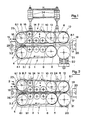
- Fig. 1 eine Ansicht einer Einrichtung zum Zubringen eines Kabels in einen Kabel-Verarbeitungsautomaten in der ausgefahrenen Ruhestellung zum Einziehen eines Kabels vor Beginn des Arbeitsprozesses,
- Fig. 2 eine Ansicht der Einrichtung zum Zubringen eines Kabels in den Kabel-Verarbeitungsautomaten in der eingefahrenen Arbeitsstellung.
- 1 is a view of a device for feeding a cable into a cable processing machine in the extended rest position for pulling in a cable before the start of the working process,
- Fig. 2 is a view of the device for feeding a cable in the cable processing machine in the retracted working position.
In den Fig. 1 und 2 ist mit 1 ein stationärer Riementrieb bezeichnet. Der stationäre Riementrieb 1 weist einen Zahnriemen 3, eine angetriebene Umlenkrolle 4 eine Umlenkrolle 5 und bespielsweise drei Druckrollen 6 auf. Die Umlenkrolle 5 und die Druckrollen 6 weisen nicht gleiche Durchmesser auf, sind aber so angeordnet, dass sie zusammen mit dem Zahnriemen 3 eine in einer Ebene liegende Antriebsfläche 3.1 bilden. Die Achse 4.1 der angetriebenen Umlenkrolle 4 ist gegenüber den Druckrollen 6 so gelagert, dass der Zahnriemen 3 mit einer Neigung 3.2 in die Antriebsfläche 3.1 einläuft. Auf der gleichen Achse 4.1 ist ein Zahnrad 7 angeordnet. Gegenüber dem stationären Riementrieb 1 ist ein verschiebbar gelagerter Riementrieb 2 vorgesehen, bestehend aus einem Zahnriemen 8, einer auf einer fest angeordneten Achse 9.1 drehbar gelagerten, angetriebenen Umlenkrolle 9 und einer verschiebbar gelagerten Tragplatte 10. Die fest angeordnete Achse 9.1 weist einen stets gleichbleibenden Achsabstand zur Achse 4.1 des stationären Riementriebs 1 auf und trägt zusätzlich ein die Umlenkrolle 9 antreibenedes Zahnrad 23, welches in das den stationären Riementrieb 1 antreibende Zahnrad 7 eingreift. Ein nicht dargestellter Antrieb greift mit einem Zahnritzel in eines der Zahnräder 7, 23 ein und treibt die beiden Riementriebe 1, 2 an. Die verschiebbar gelagerte Tragplatte 10 des verschiebbar gelagerten Riementriebes 2 ist beispielsweise auf zwei senkrecht zur Antriebsfläche 3.1 angeordneten Führungszapfen 11 gleitend geführt. Die Tragplatte 10 nimmt eine Umlenkrolle 12 eine Druckrolle 13, beispielsweise drei kleinere Druckrollen 14 und eine Ausgleichsrolle 15 auf. Die Umlenkrolle 12 und die Druckrollen 13, 14 sind auf der Tragplatte 10 so angeordnet, dass sie zusammen mit dem Zahnriemen 8 stehts eine in einer Ebene liegende und parallel zur Antriebsfläche 3.1 des festen Riementriebes 1 verlaufende Antriebsfläche 8.1 bilden. Die Tragplatte 10 kann mit Hilfe einer Antriebseinheit, beispielsweise zwei pneumatische Kolben-Zylindereinheiten 24, gegen den stationären Riementrieb 1 bewegt werden, wobei die Antriebsfläche 8.1 des verschiebbar gelagerten Riementriebes 2 gegen die Antriebsfläche 3.1 des stationären Riementriebes 1 gedrückt wird. Die Ausgleichsrolle 15 dient dazu den Zahnriemen 8 des verschiebbar gelagerten Riementriebes 2 in der ausgefahrenen Ruhestellung unter Spannung zu halten, bzw. eine Längenreserve des Zahnriemens 8, welche für die Verschiebung der Tragplatte 10 mit den Spannrollen 13, 14 und der Umlenkrolle 12 in die Arbeitsstellung benötigt wird, in der ausgefahrenen Ruhestellung aufzunehmen. Zwischen den Antriebsflächen 3.1, 8.1 der beiden aufeinander abwälzenden Zahnriemen 3, 8 ist ein Draht oder Kabel 18 eingelegt. Die Druckrollen 6 und die Umlenkrolle 5 des stationären Riementriebes 1 liegen walzenartig gegenüber den Druckrollen 14, 13 des verschiebbar gelagerten Riementriebes 2, so dass der Draht oder das Kabel 18 durch die beiden in gleicher Richtung bewegten Trums der gegenläufig angetriebenen Riementriebe 1, 2 mitbewegt wird. Auf der Kabel-Zufuhrseite 16 wird das Kabel 18 durch eine in der Achsrichtung des zugeführten Kabels 18 verschiebbar gelagerten Klemm-Spannvorrichtung 19 und auf der Kabel-Austrittseite 17 durch eine Klemmvorrichtung 20 hindurchgeführt. Nach der Klemmvorrichtung 20 ist ein nicht dargestellter Kabel-Verarbeitungsautomat mit beispielsweise einer Schneid- und einer Abisoliereinrichtung und eventuell einer Crimppresse angeordnet. Die Antriebsfläche 8.1 des verschiebbar gelagerten Riementriebes 2 ragt auf der Kabel-Austrittseite 17 mit Hilfe der Umlenkrolle 12 über die Antriebsfläche 3.1 des stationären Riementriebes 1 hinaus. Am Ende dieser auskragenden Antriebsfläche 8.1 ist gegenüber der Umlenkrolle 12 eine Treibrolle 21 einer1 and 2, 1 denotes a stationary belt drive. The
Kabel-Längenmesseinrichtung 22 angeordnet, welche mit einer justierbaren Zustellung ausgerüstet ist, die ein Mitdrehen der Treibrolle 21 durch das bewegte Kabel 18 ermöglicht, aber ein Mitdrehen bei fehlendem Kabel 18 durch den Zahnriemen 8 des verschiebbar gelagerten Riementriebes 2 verhindert.Cable
Die vorstehend beschriebene Einrichtung zum Zubringen eines elektrischen Leiters oder eines Kabels 18 in einen Kabel-Verarbeitungsautomaten arbeitet wie folgt: Ein ausgewähltes Kabel 18 wird im ausgefahrenen Ruhestand der Riementriebe 1, 2 bei nicht angetriebenen Zahnriemen 3, 8 manuell durch die Klemm-Spannvorrichtung 19, zwischen den Zahnriemen 3, 8 der beiden Riementriebe 1, 2 hindurch und durch die Klemmvorrichtung 20 geführt. Das Kabel wird von der Klemm-Spannvorrichtung 19 und von der Klemmvorrichtung 20 geklemmt, mit der Klemm-Spannvorrichtug gespannt und der verschiebbar gelagerte Riementrieb 2 beispielsweise mit Hilfe der beiden pneumatischen Kolben-Zylindereinheiten 24 zugestellt, bis das eingezogene Kabel 18 zwischen den beiden Antriebsflächen 3.1, 8.1 der Riementriebe 1, 2 festgehalten ist. Dabei wird die verschiebbar gelagerte Tragplatte 10 des verschiebbaren Riementriebes 2 zusammen mit den Druckrollen 13, 14, der Klemmrolle 12 und der Ausgleichsrolle 15, durch die beiden Führungszapfen 11 parallel geführt, gegen den stationären Riementrieb 1 gefahren, während die angetriebene Umlenkrolle 9 des verschiebbaren Riementriebes 2 ihre Lage beibehält. Die Tragplatte 10 ist durch die Führungszapfen 11 so geführt, dass sich die gebildete Antriebsfläche 8.1 des Zahnriemens 8 parallel gegen die Antriebsfläche 3.1 des Zahnriemens 3 des stationären Riementriebes 1 verschiebt. Zwischen der fest angeordneten Umlenkrolle 9 und der ersten Druckrolle 14 entsteht ein grösserer Achsabstand, so dass der Zahnriemen 2 auch beim verschiebbaren Riementrieb 2 in der eingefahrenen Arbeitsstellung (Fig. 2) mit einer Neigung 8.2 in die Antriebsfläche 8.1 einläuft. Innerhalb der beiden Neigungen 3.2, 8.2 führt eine stationäre, konisch zulaufende Führungsbüchse 25 das Kabel 18 exakt zwischen die Antriebsflächen 3.1, 8.1 der Riementriebe 1, 2. Beim Verschieben der Antriebsfläche 8.1 des verschiebbaren Riementriebes 2 gegen die Antriebsfläche 3.1 des stationären Riementriebes 1 wird der untere Riementrum des Zahnriemens 8 gespannt, während gleichzeitig der obere Riementrum durch das Mitbewegen der Ausgleichsrolle 15 entlastet wird. Die Ausgleichsrolle 15 bewirkt, dass der verschiebbare Riementrieb trotz feststehender, angetriebener Umlenkrolle 9 in jeder Stellung zwischen ausgefahrener Ruhestellung (Fig. 1) und der eingefahrenen Arbeitsstellung (Fig. 2) ungefähr die gleiche Riemenspannung aufweist. Beide Zahnriemen 3.8 sind durch je eine nicht dargestellte Spannvorrichtung zusätzlich spannbar. Durch die über die Antriebsfläche 3.1 des stationären Riementriebes 1 hinausragende Antriebsfläche 8.1 des verschiebaren Riementriebes 2 kommt auch die Oberfläche der Treibrolle 2 der Kabel-Längenmesseinrichtung 22 mit dem festgeklemmten Kabel 18 in Berührung. Die Treibrolle 21 der Kabel-Längenmesseinrichtung 22 kann einen limitierten Weg senkrecht zur Bewegungsrichtung des Kabels 18 ausführen und wird durch die Kraft von Federn an das Kabel 18 angedrückt und später durch das bewegte Kabel 18 angetrieben.The device described above for feeding an electrical conductor or a
Die Klemmvorrichtung 20 und die Klemm-Spannvorrichtung 19 werden nun gelöst und gleichzeitig der Antrieb für die Riementriebe eingeschaltet, welcher über die Zahnräder 7, 23 beide Riementriebe 1, 2 gleichzeitig und mit gleicher Geschwindigkeit antreibt. Das Kabel 18 wird vorwärtsbewegt und das Kabelende durch die nicht dargestellte Schneidvorrichtung geleitet, angehalten und ein erster Schnitt ausgführt, das Ende des Kabels abisoliert und mit einem Crimpkontakt versehen. Der Kabel-Längenmesseinrichtung wird eine bestimmte Kabellänge vorgegeben. Der Kabelzubringer ist damit bereit für den automatischen Betrieb, bei welchem die beiden angetriebenen Riementriebe das Kabel vorwärtsbewegen. Das Kabel seinerseits treibt die Treibrolle der Kabel-Längenmesseinrichtung an, bis die vorgegebene Kabellänge erreicht ist und die Längenmesseinrichtung den Impuls zum Stillsetzen der Riementriebe gibt und das Steuerprogramm zum Festhalten des Kabels in der Schneidvorrichtung, zum Betätigen des Schneidmessers der Abisoliereinrichtung, der Crimppresse etc. und zur Wiederholung des beschriebenen Vorganges einsetzt.The
In den Fig. 1 und 2 und in der vorliegenden Beschreibung sind zwei Riementriebe dargestellt, in welchen der stationäre Riementrieb vier in einer Ebene angeordnete Rollen und der verschiebbare Riementrieb fünf in einer Ebene angeordnete Rollen aufweist, die je zusammen mit dem zugehörigen Zahnriemen zwei gegeneinandergerichtete Antriebsflächen bilden. Es ist ohne weiteres denkbar, dass auch weniger oder mehr Rollen zur Bildung solcher Antriebsflächen dienen können, es ist aber darauf zu achten, dass stets eine Rolle des stationären Riementriebes mit einer gegenüberliegenden Rolle des verschiebbaren Riementriebes zusammenarbeitet, und dass der verschiebbare Riementrieb in einer Antriebsebene stets eine Rolle mehr aufweist als der feste Riementrieb, wodurch eine die Antriebsfläche des festen Riementriebes überragende Antriebsfläche entsteht, auf der mit Hilfe des mitbewegten Kabels die Treibrolle der Kabel-Längenmesseinrichtung angetrieben wird.1 and 2 and in the present description, two belt drives are shown, in which the stationary belt drive has four rollers arranged in one plane and the displaceable belt drive has five rollers arranged in one plane, each of which, together with the associated toothed belt, has two opposing drive surfaces form. It is readily conceivable that fewer or more rollers can also be used to form such drive surfaces, but it must be ensured that one roller of the stationary belt drive always works together with an opposite roller of the displaceable belt drive, and that the displaceable belt drive is in one drive plane always has one roll more than the fixed belt drive, which creates a drive surface which projects beyond the drive surface of the fixed belt drive and on which the driving roller of the cable length measuring device is driven with the aid of the moving cable.
Für die beiden beschriebenen Riementriebe sind zwei gleichartige, handelsübliche Zahnriemen vorgesehen. Es ist aber ohne weiteres denkbar zwei Zahnriemen mit unterschiedlichen Oberflächenhärten für eine weichere und eine härtere Antriebsfläche vorzusehen oder ein Riementrieb mit einem Doppelzahnriemen und der zweite mit einem normalen Zahnriemen auszurüsten.Two identical, commercially available toothed belts are provided for the two belt drives described. But it is easily conceivable two timing belts with different To provide surface hardness for a softer and a harder drive surface or to equip one belt drive with a double toothed belt and the second with a normal toothed belt.
Anstelle des in der Beschreibung erwähnten manuellen Einbringens eines ausgewählten Kabels in den Kabelzubringer, ist es ohne weiteres denkbar, eine Einrichtung vorzusehen, welche ein vorgegebenes Kabel auswählt und dieses automatisch in den Kabelzubringer einlegt.Instead of manually inserting a selected cable into the cable feeder as mentioned in the description, it is readily conceivable to provide a device which selects a predetermined cable and automatically inserts it into the cable feeder.
Claims (6)
dadurch gekennzeichnet,
- dass ein ausgewähltes Kabel (18) durch eine Kabel-Klemm-Spannvorrichtung (19) hindurchführt, zwischen die auseinandergefahrenen Antriebsflächen (3.1), (8.1) der Zahnriemen (3, 8) eines stationären (1) und eines verschiebbar gelagerten Riementriebes (2) und über die Treibrolle (21) einer Kabel-Längenmesseinrichtung (22) gelegt und durch eine Kabel-Klemmvorrichtung (20) hindurchgeführt wird,
- dass das Kabel (18) von der Klemm- Spannvorrichtung (19) und der Klemmvorrichtung (20) geklemmt und durch eine Verschiebung der Klemm-Spannvorrichtung (19) gespannt wird,
- dass der verschiebbar gelagerte Riementrieb (2) auf das gespannte Kabel (18) aufgeschoben und durch eine Kraft aufgedrückt wird,
- dass die beiden Riementriebe (1, 2) bei gleichzeitigem Öffnen der Klemm-Spannvorrichtung (19) und Klemmvorrichtung (20) in entgegengesetzter Drehrichtung angetrieben werden, wobei das Kabel (18) vorwärtsbewegt und die Treibrolle (21) der Kabel-Längenmesseinrichtung (22) angetrieben wird und
- dass die Bewegung des Kabels (18) unterbrochen, dann die genaue vorgegebene Kabellänge eingependelt und der Kabel-Verarbeitungsautomat mit einer Schneid- und einer Abisoliereinrichtung und eventuell einer Crimppresse angesteuert wird, wobei das Kabel (18) geschnitten, beide entstehenden Kabelenden abisoliert und eventuell mit einem Crimpkontakt versehen werden, das abgeschnittene Kabel (18) weggeführt und das verbleibende Kabel (18) um die vorgewählte Kabellänge wieder vorwärts bewegt wird.1. Method for feeding a cable into a cable processing machine,
characterized,
- That a selected cable (18) passes through a cable clamp tensioning device (19), between the extended drive surfaces (3.1), (8.1) of the toothed belt (3, 8) of a stationary (1) and a slidably mounted belt drive (2 ) and placed over the drive roller (21) of a cable length measuring device (22) and passed through a cable clamping device (20),
- That the cable (18) from the clamping device (19) and the clamping device (20) is clamped and tensioned by displacement of the clamping device (19),
- That the displaceably mounted belt drive (2) is pushed onto the tensioned cable (18) and pressed on by a force,
- That the two belt drives (1, 2) while simultaneously opening the clamping tensioning device (19) and clamping device (20) are driven in the opposite direction of rotation, the cable (18) moving forward and the drive roller (21) of the cable length measuring device (22nd ) is driven and
- That the movement of the cable (18) is interrupted, then the exact predetermined cable length is leveled out and the cable processing machine is controlled with a cutting and stripping device and possibly a crimping press, the cable (18) being cut, both stripped cable ends and possibly stripped be provided with a crimp contact, the cut cable (18) is led away and the remaining cable (18) is moved forward again by the preselected cable length.
dadurch gekennzeichnet,
dass der erste, fest angeordnete Riementrieb (1) eine zwischen der nicht angetriebenen Umlenkrolle (5) und mindestens einer Druckrolle (6) gebildete Antriebsfläche (3.1) des Zahnriemens (3) aufweist und die Anpresseinrichtung des zweiten Riementriebes (2) eine Druckplatte (10), eine gegeüber der nicht angetriebenen Umlenkrolle (5) angeordnete Druckrolle (13), eine vorgezogene Umlenkrolle (12) und mindestens eine weitere Druckrolle (14) aufweist, wobei die Umlenkrolle (12) und die Druckrollen (13, 14) mit dem Zahnriemen (8) eine über die Antriebsfläche (3.1), des festen Riementriebes (1) hinausragende Antriebsfläche (8.1) bildet, dass an der Druckplatte (10) mindestens eine die Antriebsfläche (8.1) des zweiten Riementriebes (2) gegen die Antriebsfläche (3.1) des ersten Riementriebes (1) verschiebbare pneumatische Kolben-Zylindereinheit angelenkt ist, dass eine Treibrolle (21) der Kabel-Längenmesseinrichtung im Bereich der auskragenden Antriebsfläche (8.1), gegenüber der Umlenkrolle (12) des zweiten Riementriebes (2) angeordnet ist, und dass auf der Kabel-Zufuhrseite (16) eine in der Achsrichtung des Kabels (18) verschiebbar gelagerte, das Kabel (18) klemmende und spannende Klemm-Spannvorrichtung (10) und auf der Kabel-Austrittseite (17) eine das Kabel (18) klemmende, feste Klemmvorrichtung (20) vorgesehen ist.2. Device for carrying out the delivery process a cable into an automatic cable processing machine, with two belt drives (1, 2) facing each other and a cable length measuring device (22) measuring the predetermined length of a cable section, a first belt drive (1) with two deflection rollers (4, 5) and a toothed belt (3) is arranged in a fixed manner and a second belt drive has a fixed, drivable deflection roller (9) and a pressing device, which is displaceable parallel to the feed direction of the cable (18) and has a second deflection roller and which, by force, has the toothed belt (8) of the second belt drive (2) presses against the toothed belt (3) of the first belt drive (1) or against the cable (18) inserted between the two toothed belts (3, 8) and the cable (18) through both driven toothed belts (3, 8) moved against the wire processing machine,
characterized,
that the first, firmly arranged belt drive (1) has a drive surface (3.1) of the toothed belt (3) formed between the non-driven deflection roller (5) and at least one pressure roller (6) and the pressing device of the second belt drive (2) has a pressure plate (10 ), a pressure roller (13) arranged opposite the non-driven deflection roller (5), an advanced deflection roller (12) and at least one further pressure roller (14), the deflection roller (12) and the pressure rollers (13, 14) with the toothed belt (8) a drive surface (8.1) projecting beyond the drive surface (3.1) of the fixed belt drive (1) forms that on the pressure plate (10) at least one the drive surface (8.1) of the second belt drive (2) against the drive surface (3.1) of the first belt drive (1) displaceable pneumatic piston-cylinder unit is articulated that a drive roller (21) of the cable length measuring device in the area of the projecting drive surface (8.1), opposite the deflection roller (12) of the second belt drive (2) is arranged, and that on the cable feed side (16) a clamp-type clamping device (10) which is displaceably mounted in the axial direction of the cable (18) and clamps and clamps the cable (18), and a fixed clamp (20) which clamps the cable (18) is provided on the cable outlet side (17) .
dadurch gekennzeichnet,
dass auf der Tragplatte (10) des verschiebbar gelagerten Riementriebes (2) eine den losen Trum bei zurückgefahrenem Riementrieb (2) spannende Ausgleichsrolle (15) angeordnet ist.3. Device according to claim 2,
characterized,
that on the support plate (10) of the displaceably mounted belt drive (2) there is arranged a compensating roller (15) exciting the loose strand when the belt drive (2) is retracted.
dadurch gekennzeichnet,
dass die beiden Zahnriemen (3, 8) unterschiedlich harte Antriebsflächen (3.1, 8.1) zum Antreiben des Kabels (18) aufweisen.4. Device according to claim 2,
characterized,
that the two toothed belts (3, 8) have drive surfaces (3.1, 8.1) of different hardness for driving the cable (18).
dadurch gekennzeichnet,
dass mindestens ein Zahnriemen (3, 8) der Riementriebe (1, 2) ein Doppelzahnriemen ist.5. Device according to claim 2,
characterized,
that at least one toothed belt (3, 8) of the belt drives (1, 2) is a double toothed belt.
dadurch gekennzeichnet,
dass die vom bewegten Kabel (18) angetriebene Treibrolle (21) der Kabel-Längenmesseinrichtung (22) eine justierbare, den Zahnriemen (8) bei fehlendem Kabel (18) nicht berührende, durch die Kraft von Federn an das Kabel andrückende Zustelleinrichtung aufweist.6. Device according to claim 2,
characterized,
that the driven roller (21) of the cable length measuring device (22) driven by the moving cable (18) has an adjustable feed device which does not touch the toothed belt (8) when the cable (18) is missing and presses against the cable by the force of springs.
Applications Claiming Priority (2)
| Application Number | Priority Date | Filing Date | Title |
|---|---|---|---|
| CH3786/89 | 1989-10-18 | ||
| CH378689 | 1989-10-18 |
Publications (2)
| Publication Number | Publication Date |
|---|---|
| EP0423443A1 true EP0423443A1 (en) | 1991-04-24 |
| EP0423443B1 EP0423443B1 (en) | 1994-09-28 |
Family
ID=4263451
Family Applications (1)
| Application Number | Title | Priority Date | Filing Date |
|---|---|---|---|
| EP90114421A Expired - Lifetime EP0423443B1 (en) | 1989-10-18 | 1990-07-27 | Process and device for carrying-out the process to feed a cable into a cable manufacturing automaton |
Country Status (4)
| Country | Link |
|---|---|
| US (1) | US5109598A (en) |
| EP (1) | EP0423443B1 (en) |
| JP (1) | JP2904440B2 (en) |
| DE (1) | DE59007328D1 (en) |
Cited By (15)
| Publication number | Priority date | Publication date | Assignee | Title |
|---|---|---|---|---|
| US5235735A (en) * | 1991-04-17 | 1993-08-17 | Ttc Technology Trading Company | Apparatus for cutting and insulation stripping of an electrical cable |
| US5368212A (en) * | 1991-01-21 | 1994-11-29 | Ttc Technology Trading Company | Apparatus for infeeding a cable to an automatic cable processing machine |
| EP0655812A2 (en) * | 1993-11-30 | 1995-05-31 | Molex Incorporated | Multi-wire feeding apparatus |
| EP0707365A1 (en) * | 1990-11-09 | 1996-04-17 | Eubanks Engineering Company | Multiple blade set strip apparatus for cable and wire |
| US5515602A (en) * | 1990-11-09 | 1996-05-14 | Eubanks Engineering Company | Multiple blade set strip apparatus for cable and wire |
| US5517882A (en) * | 1990-11-09 | 1996-05-21 | Eubanks Engineering Company | Wire and cable cutting and stripping using slidable interfitting blades with complementary configurations |
| WO1997017751A1 (en) * | 1995-11-06 | 1997-05-15 | Schleuniger Holding Ag | Insulation stripping device |
| US5630341A (en) * | 1990-11-09 | 1997-05-20 | Eubanks Engineering Co. | Method for processing cable and wire |
| US5653016A (en) * | 1990-11-09 | 1997-08-05 | Eubanks Engineering Company | Wire and cable drive apparatus in wire and cable cutting and stripping system |
| US6272740B1 (en) | 1990-11-09 | 2001-08-14 | Eubanks Engineering Co. | Wire and cable cutting and stripping using endless belt conveyors |
| WO2002057169A1 (en) * | 2001-01-19 | 2002-07-25 | Maillefer S.A. | Arrangement for belt drive device |
| US6910256B2 (en) * | 1995-11-06 | 2005-06-28 | Schleuniger Holding Ag | Continuous cable processing apparatus |
| CN109160368A (en) * | 2018-09-12 | 2019-01-08 | 徐州领君仁驰自动化设备有限公司 | A kind of wire stripper takes turns simple gearbox more |
| EP3544131A1 (en) | 2018-03-23 | 2019-09-25 | Komax Holding Ag | Cable processing machine with movable guiding elements and method of inserting a cable into a cable processing machine |
| CN113353721A (en) * | 2021-06-28 | 2021-09-07 | 湖南天剑海洋工程设备有限公司 | Cable traction device and clamping mechanism thereof |
Families Citing this family (27)
| Publication number | Priority date | Publication date | Assignee | Title |
|---|---|---|---|---|
| US5343605A (en) * | 1991-09-26 | 1994-09-06 | Eubanks Engineering Company | Wire marking, cutting and stripping apparatus and method |
| US5528962A (en) * | 1990-11-09 | 1996-06-25 | Eubanks Engineering Company | Multiple blade set strip apparatus for cable and wire |
| US5469763A (en) * | 1990-11-09 | 1995-11-28 | Eubanks Engineering Company | Wire and cable processing system |
| US5317812A (en) * | 1992-03-06 | 1994-06-07 | Artos Engineering | Wire feeding and measuring apparatus |
| US5681131A (en) * | 1995-07-18 | 1997-10-28 | The Consumers' Gas Company Ltd. | Cable feeding system and umbilical cable therefor |
| US5809849A (en) * | 1996-02-08 | 1998-09-22 | Coffey; Kevin M. | Machine for stripping insulation from wire |
| JP4085185B2 (en) * | 1997-02-14 | 2008-05-14 | モレックス インコーポレーテッド | Wire length measuring device in multi-electric harness manufacturing equipment |
| US6073916A (en) * | 1998-10-08 | 2000-06-13 | Greenlee Textron Inc. | Powered cable feeding system |
| SE516117C2 (en) * | 1999-05-27 | 2001-11-19 | Abb Ab | Equipment and method for providing and producing a winding of electric cable in an electric machine |
| US8161786B2 (en) * | 2008-04-15 | 2012-04-24 | Glen Stapleton | Apparatus for feeding and turning tube products into a pilger mill machine |
| GB0817639D0 (en) | 2008-09-26 | 2008-11-05 | British Telecomm | Cable installation apparatus |
| EP2230545A1 (en) | 2009-03-19 | 2010-09-22 | BRITISH TELECOMMUNICATIONS public limited company | Passive remote air flow and cable detection |
| GB0905590D0 (en) * | 2009-03-31 | 2009-05-13 | British Telecomm | Blown cable apparatus |
| CN102195226B (en) * | 2010-03-12 | 2014-09-03 | 库迈思控股股份公司 | Cable supplying and rotating system |
| EP2369388A1 (en) | 2010-03-26 | 2011-09-28 | British Telecommunications public limited company | Optical fibre splice tray assembly |
| CN102446589B (en) * | 2011-08-31 | 2013-07-03 | 白城福佳机械制造有限公司 | Belt dragger |
| SG11201600273TA (en) * | 2013-07-16 | 2016-02-26 | Daewoo Shipbuilding & Marine | Gripper device for wire laying |
| CN104112546A (en) * | 2014-07-08 | 2014-10-22 | 平湖迪工机械制造有限公司 | Cable former |
| CN104692185A (en) * | 2015-01-09 | 2015-06-10 | 芜湖航天特种电缆厂 | Tractor |
| DK3101746T3 (en) * | 2015-06-03 | 2019-03-18 | As P K Jeppesen Og Soen Næstved | A cable feed module for feeding cables or pipes |
| CN105119129A (en) * | 2015-08-31 | 2015-12-02 | 芜湖顺成电子有限公司 | Wire stripping device |
| AU2017259934A1 (en) | 2016-05-05 | 2018-11-22 | Stoneage, Inc. | Endless belt flexible tube cleaning lance drive apparatus |
| CN106602383A (en) * | 2016-12-31 | 2017-04-26 | 东莞市贺众精密机械有限公司 | Terminal crimping machine having two-core-wire separating function |
| CN108584534A (en) * | 2018-06-01 | 2018-09-28 | 嘉兴市华益股份有限公司 | A kind of continuous rolling-up mechanism of mixed yarn |
| JP2022515956A (en) * | 2018-10-31 | 2022-02-24 | シュロニガー アーゲー | How to operate the straightening device and straightening unit of the cable processing machine |
| CN112660928B (en) * | 2021-03-16 | 2022-01-21 | 国网山东省电力公司安丘市供电公司 | Electric cable pay-off device |
| CN113602899B (en) * | 2021-07-15 | 2023-01-10 | 蓝德能源科技股份有限公司 | Nondestructive cable processing traction mechanism and method |
Citations (3)
| Publication number | Priority date | Publication date | Assignee | Title |
|---|---|---|---|---|
| DE2047460A1 (en) * | 1969-09-29 | 1971-04-15 | Gen Electric | Wire cutting and abisohervor direction |
| GB2077518A (en) * | 1980-05-30 | 1981-12-16 | Yazaki Corp | Method and apparatus for processing insulated wide |
| EP0185788A1 (en) * | 1984-12-21 | 1986-07-02 | Audi Ag | Wire-feeding device for an insulated wire cutting and stripping apparatus |
Family Cites Families (6)
| Publication number | Priority date | Publication date | Assignee | Title |
|---|---|---|---|---|
| US3368428A (en) * | 1966-09-12 | 1968-02-13 | Artos Engineering Co | Wire cutting and stripping machine |
| US3874076A (en) * | 1971-03-26 | 1975-04-01 | Sumitomo Electric Industries | Method and apparatus for manufacturing soft metal sheaths for electrical wires |
| US4043362A (en) * | 1976-02-09 | 1977-08-23 | Gardner-Denver Company | Cutting and insulation stripping apparatus for twisted wire pair |
| US4179056A (en) * | 1976-08-16 | 1979-12-18 | Chemetron Corporation | Wire-feeding mechanism |
| US4521946A (en) * | 1982-03-31 | 1985-06-11 | Artos Engineering Company | Cutter and belt type conveyor for wire segments |
| DE3643201A1 (en) * | 1986-12-18 | 1988-06-30 | Statomat Globe Maschf | METHOD AND DEVICE FOR CUTTING CABLES FROM A CABLE STOCK FOR PROCESSING THE CABLE END |
-
1990
- 1990-07-27 DE DE59007328T patent/DE59007328D1/en not_active Expired - Fee Related
- 1990-07-27 EP EP90114421A patent/EP0423443B1/en not_active Expired - Lifetime
- 1990-08-22 US US07/571,325 patent/US5109598A/en not_active Expired - Lifetime
- 1990-09-26 JP JP2256778A patent/JP2904440B2/en not_active Expired - Fee Related
Patent Citations (3)
| Publication number | Priority date | Publication date | Assignee | Title |
|---|---|---|---|---|
| DE2047460A1 (en) * | 1969-09-29 | 1971-04-15 | Gen Electric | Wire cutting and abisohervor direction |
| GB2077518A (en) * | 1980-05-30 | 1981-12-16 | Yazaki Corp | Method and apparatus for processing insulated wide |
| EP0185788A1 (en) * | 1984-12-21 | 1986-07-02 | Audi Ag | Wire-feeding device for an insulated wire cutting and stripping apparatus |
Cited By (21)
| Publication number | Priority date | Publication date | Assignee | Title |
|---|---|---|---|---|
| US6272740B1 (en) | 1990-11-09 | 2001-08-14 | Eubanks Engineering Co. | Wire and cable cutting and stripping using endless belt conveyors |
| US5630341A (en) * | 1990-11-09 | 1997-05-20 | Eubanks Engineering Co. | Method for processing cable and wire |
| EP0707365A1 (en) * | 1990-11-09 | 1996-04-17 | Eubanks Engineering Company | Multiple blade set strip apparatus for cable and wire |
| US5515602A (en) * | 1990-11-09 | 1996-05-14 | Eubanks Engineering Company | Multiple blade set strip apparatus for cable and wire |
| US5517882A (en) * | 1990-11-09 | 1996-05-21 | Eubanks Engineering Company | Wire and cable cutting and stripping using slidable interfitting blades with complementary configurations |
| US5653016A (en) * | 1990-11-09 | 1997-08-05 | Eubanks Engineering Company | Wire and cable drive apparatus in wire and cable cutting and stripping system |
| US5368212A (en) * | 1991-01-21 | 1994-11-29 | Ttc Technology Trading Company | Apparatus for infeeding a cable to an automatic cable processing machine |
| US5235735A (en) * | 1991-04-17 | 1993-08-17 | Ttc Technology Trading Company | Apparatus for cutting and insulation stripping of an electrical cable |
| EP0655812A3 (en) * | 1993-11-30 | 1997-02-05 | Molex Inc | Multi-wire feeding apparatus. |
| EP0655812A2 (en) * | 1993-11-30 | 1995-05-31 | Molex Incorporated | Multi-wire feeding apparatus |
| WO1997017751A1 (en) * | 1995-11-06 | 1997-05-15 | Schleuniger Holding Ag | Insulation stripping device |
| EP1271729A2 (en) * | 1995-11-06 | 2003-01-02 | Schleuniger Holding AG | Insulation stripping device |
| EP1271729A3 (en) * | 1995-11-06 | 2003-08-06 | Schleuniger Holding AG | Insulation stripping device |
| US6910256B2 (en) * | 1995-11-06 | 2005-06-28 | Schleuniger Holding Ag | Continuous cable processing apparatus |
| US8234772B2 (en) | 1995-11-06 | 2012-08-07 | Schleuniger Holding Ag | Continuous cable processing apparatus |
| WO2002057169A1 (en) * | 2001-01-19 | 2002-07-25 | Maillefer S.A. | Arrangement for belt drive device |
| US7293682B2 (en) | 2001-01-19 | 2007-11-13 | Maillefer S.A. | Arrangement for belt drive device |
| EP3544131A1 (en) | 2018-03-23 | 2019-09-25 | Komax Holding Ag | Cable processing machine with movable guiding elements and method of inserting a cable into a cable processing machine |
| US10974924B2 (en) | 2018-03-23 | 2021-04-13 | Komax Holding Ag | Cable processing machine with movable guide elements and method for laying a cable in a cable processing machine |
| CN109160368A (en) * | 2018-09-12 | 2019-01-08 | 徐州领君仁驰自动化设备有限公司 | A kind of wire stripper takes turns simple gearbox more |
| CN113353721A (en) * | 2021-06-28 | 2021-09-07 | 湖南天剑海洋工程设备有限公司 | Cable traction device and clamping mechanism thereof |
Also Published As
| Publication number | Publication date |
|---|---|
| JP2904440B2 (en) | 1999-06-14 |
| US5109598A (en) | 1992-05-05 |
| DE59007328D1 (en) | 1994-11-03 |
| JPH03179616A (en) | 1991-08-05 |
| EP0423443B1 (en) | 1994-09-28 |
Similar Documents
| Publication | Publication Date | Title |
|---|---|---|
| EP0423443B1 (en) | Process and device for carrying-out the process to feed a cable into a cable manufacturing automaton | |
| EP0496049B1 (en) | Improvement to the device for feeding a cable into an automatic cable manufacturing machine | |
| EP0185788B1 (en) | Wire-feeding device for an insulated wire cutting and stripping apparatus | |
| EP0598276B1 (en) | Cable feeding and changing device for a cable processing machine | |
| DE3338915C2 (en) | ||
| DE2548771B2 (en) | Feed and clamping device for a cutting machine | |
| EP0161657A2 (en) | Device for guiding a wire or tape electrode cutter in a machine tool | |
| AT518608B1 (en) | Kantenanleimvorrichtung | |
| DE2420690B2 (en) | DEVICE FOR BENDING TUBE SECTIONS | |
| DE4019285A1 (en) | CLAMPING DEVICE FOR TARGETED CLAMPING OF WORKPIECES | |
| DE2647222B2 (en) | Device for cutting, untwisting and stripping of adjacent areas of a given length of an insulated, twisted pair of electrical conductors | |
| AT390025B (en) | DEVICE FOR PRODUCING PRISMATIC OR PYRAMID-BASED BARS | |
| DE911347C (en) | Device for feeding similar workpieces stacked one on top of the other, e.g. bolt | |
| DE4441301C1 (en) | Appts. for prodn. of pretzels from dough strands | |
| CH683809A5 (en) | Method and apparatus for cutting and stripping jacketed cable. | |
| DE19917028A1 (en) | Wire drawing machines saving space | |
| EP0236688A2 (en) | Process for changing electrical conductors when mounting electrical connectors, and apparatus for carrying out the process | |
| DE3338096A1 (en) | Method and apparatus for the cutting-to-length of elongated metal material | |
| DE3443754C2 (en) | ||
| DE3504713C2 (en) | ||
| DE2910633A1 (en) | Transistor terminal lead trimmer - has guide groove perpendicular to tools and in line with friction feed wheel | |
| DE4111431C2 (en) | Method and device for producing endless steel strips | |
| DE19519395C1 (en) | Rod material drawing machine, and method | |
| EP1126945B1 (en) | Device for bending and separating an endpiece from a strand of material | |
| DE2412586C3 (en) | Device for applying a shrink tube to a wiring element or the like |
Legal Events
| Date | Code | Title | Description |
|---|---|---|---|
| PUAI | Public reference made under article 153(3) epc to a published international application that has entered the european phase |
Free format text: ORIGINAL CODE: 0009012 |
|
| AK | Designated contracting states |
Kind code of ref document: A1 Designated state(s): CH DE FR IT LI |
|
| 17P | Request for examination filed |
Effective date: 19910926 |
|
| 17Q | First examination report despatched |
Effective date: 19930519 |
|
| GRAA | (expected) grant |
Free format text: ORIGINAL CODE: 0009210 |
|
| AK | Designated contracting states |
Kind code of ref document: B1 Designated state(s): CH DE FR IT LI |
|
| REF | Corresponds to: |
Ref document number: 59007328 Country of ref document: DE Date of ref document: 19941103 |
|
| ET | Fr: translation filed | ||
| ITF | It: translation for a ep patent filed |
Owner name: MODIANO & ASSOCIATI S.R.L. |
|
| PLBE | No opposition filed within time limit |
Free format text: ORIGINAL CODE: 0009261 |
|
| STAA | Information on the status of an ep patent application or granted ep patent |
Free format text: STATUS: NO OPPOSITION FILED WITHIN TIME LIMIT |
|
| 26N | No opposition filed | ||
| PGFP | Annual fee paid to national office [announced via postgrant information from national office to epo] |
Ref country code: DE Payment date: 20080722 Year of fee payment: 19 |
|
| PGFP | Annual fee paid to national office [announced via postgrant information from national office to epo] |
Ref country code: IT Payment date: 20080725 Year of fee payment: 19 Ref country code: FR Payment date: 20080715 Year of fee payment: 19 |
|
| PGFP | Annual fee paid to national office [announced via postgrant information from national office to epo] |
Ref country code: CH Payment date: 20091016 Year of fee payment: 20 |
|
| REG | Reference to a national code |
Ref country code: FR Ref legal event code: ST Effective date: 20100331 |
|
| PG25 | Lapsed in a contracting state [announced via postgrant information from national office to epo] |
Ref country code: FR Free format text: LAPSE BECAUSE OF NON-PAYMENT OF DUE FEES Effective date: 20090731 |
|
| PG25 | Lapsed in a contracting state [announced via postgrant information from national office to epo] |
Ref country code: DE Free format text: LAPSE BECAUSE OF NON-PAYMENT OF DUE FEES Effective date: 20100202 |
|
| REG | Reference to a national code |
Ref country code: CH Ref legal event code: PL |
|
| PG25 | Lapsed in a contracting state [announced via postgrant information from national office to epo] |
Ref country code: IT Free format text: LAPSE BECAUSE OF NON-PAYMENT OF DUE FEES Effective date: 20090727 |