EP0396030B1 - Heating apparatus for a machine for working plastic materials - Google Patents
Heating apparatus for a machine for working plastic materials Download PDFInfo
- Publication number
- EP0396030B1 EP0396030B1 EP90108018A EP90108018A EP0396030B1 EP 0396030 B1 EP0396030 B1 EP 0396030B1 EP 90108018 A EP90108018 A EP 90108018A EP 90108018 A EP90108018 A EP 90108018A EP 0396030 B1 EP0396030 B1 EP 0396030B1
- Authority
- EP
- European Patent Office
- Prior art keywords
- temperature control
- control means
- loop
- shells
- bending
- Prior art date
- Legal status (The legal status is an assumption and is not a legal conclusion. Google has not performed a legal analysis and makes no representation as to the accuracy of the status listed.)
- Expired - Lifetime
Links
Images


Classifications
-
- B—PERFORMING OPERATIONS; TRANSPORTING
- B29—WORKING OF PLASTICS; WORKING OF SUBSTANCES IN A PLASTIC STATE IN GENERAL
- B29C—SHAPING OR JOINING OF PLASTICS; SHAPING OF MATERIAL IN A PLASTIC STATE, NOT OTHERWISE PROVIDED FOR; AFTER-TREATMENT OF THE SHAPED PRODUCTS, e.g. REPAIRING
- B29C45/00—Injection moulding, i.e. forcing the required volume of moulding material through a nozzle into a closed mould; Apparatus therefor
- B29C45/17—Component parts, details or accessories; Auxiliary operations
- B29C45/72—Heating or cooling
- B29C45/74—Heating or cooling of the injection unit
-
- B—PERFORMING OPERATIONS; TRANSPORTING
- B29—WORKING OF PLASTICS; WORKING OF SUBSTANCES IN A PLASTIC STATE IN GENERAL
- B29C—SHAPING OR JOINING OF PLASTICS; SHAPING OF MATERIAL IN A PLASTIC STATE, NOT OTHERWISE PROVIDED FOR; AFTER-TREATMENT OF THE SHAPED PRODUCTS, e.g. REPAIRING
- B29C48/00—Extrusion moulding, i.e. expressing the moulding material through a die or nozzle which imparts the desired form; Apparatus therefor
- B29C48/25—Component parts, details or accessories; Auxiliary operations
- B29C48/78—Thermal treatment of the extrusion moulding material or of preformed parts or layers, e.g. by heating or cooling
- B29C48/80—Thermal treatment of the extrusion moulding material or of preformed parts or layers, e.g. by heating or cooling at the plasticising zone, e.g. by heating cylinders
- B29C48/83—Heating or cooling the cylinders
- B29C48/832—Heating
-
- B—PERFORMING OPERATIONS; TRANSPORTING
- B29—WORKING OF PLASTICS; WORKING OF SUBSTANCES IN A PLASTIC STATE IN GENERAL
- B29C—SHAPING OR JOINING OF PLASTICS; SHAPING OF MATERIAL IN A PLASTIC STATE, NOT OTHERWISE PROVIDED FOR; AFTER-TREATMENT OF THE SHAPED PRODUCTS, e.g. REPAIRING
- B29C48/00—Extrusion moulding, i.e. expressing the moulding material through a die or nozzle which imparts the desired form; Apparatus therefor
- B29C48/25—Component parts, details or accessories; Auxiliary operations
- B29C48/78—Thermal treatment of the extrusion moulding material or of preformed parts or layers, e.g. by heating or cooling
- B29C48/80—Thermal treatment of the extrusion moulding material or of preformed parts or layers, e.g. by heating or cooling at the plasticising zone, e.g. by heating cylinders
- B29C48/83—Heating or cooling the cylinders
- B29C48/834—Cooling
-
- B—PERFORMING OPERATIONS; TRANSPORTING
- B29—WORKING OF PLASTICS; WORKING OF SUBSTANCES IN A PLASTIC STATE IN GENERAL
- B29C—SHAPING OR JOINING OF PLASTICS; SHAPING OF MATERIAL IN A PLASTIC STATE, NOT OTHERWISE PROVIDED FOR; AFTER-TREATMENT OF THE SHAPED PRODUCTS, e.g. REPAIRING
- B29C48/00—Extrusion moulding, i.e. expressing the moulding material through a die or nozzle which imparts the desired form; Apparatus therefor
- B29C48/03—Extrusion moulding, i.e. expressing the moulding material through a die or nozzle which imparts the desired form; Apparatus therefor characterised by the shape of the extruded material at extrusion
- B29C48/09—Articles with cross-sections having partially or fully enclosed cavities, e.g. pipes or channels
Landscapes
- Engineering & Computer Science (AREA)
- Mechanical Engineering (AREA)
- Physics & Mathematics (AREA)
- Thermal Sciences (AREA)
- Manufacturing & Machinery (AREA)
- Injection Moulding Of Plastics Or The Like (AREA)
- Extrusion Moulding Of Plastics Or The Like (AREA)
- Bending Of Plates, Rods, And Pipes (AREA)
- Processing And Handling Of Plastics And Other Materials For Molding In General (AREA)
- Control Of Temperature (AREA)
Abstract
Description
Die Erfindung betrifft eine Temperiereinrichtung an einer Kunststoffe verarbeitenden Maschine entsprechend dem Oberbegriff des Patentanspruches 1.The invention relates to a temperature control device on a plastics processing machine in accordance with the preamble of
Unter "Temperiereinrichtung" im Sinne des Oberbegriffes wird eine Einrichtung verstanden, die befähigt ist, dem Plastifizierzylinder eine derartige Menge an Wärme zeitgerecht zuzuführen oder zu entziehen, daß die nach dem Arbeitsprogramm der Maschine erforderlichen Temperaturen laufend realisiert werden."Tempering device" in the sense of the preamble is understood to be a device that is capable of supplying or removing such an amount of heat from the plasticizing cylinder in a timely manner that the temperatures required according to the work program of the machine are continuously achieved.
Unter dem Begriff "rohrartiges Temperierelement" wird ein Energie zuführendes oder ein Energie entziehendes Element gleichermaßen verstanden. Im ersten Falle handelt es sich um ein durch Biegen verformtes Widerstandsheizrohr, in welchem wenigstens ein Widerstandsdraht mittels eines elektrisch isolierenden, jedoch gut wärmeleitenden Pulvers (z.B. Silicat-Pulver) etwa zentrisch eingebettet ist. Im zweiten Falle handelt es sich um ein metallenes Rohr, das für den Durchfluß eines flüssigen Kühlmediums geeignet ist.The term “tube-like temperature control element” is understood to mean an energy-supplying or an energy-extracting element. In the first case, it is a resistance heating tube deformed by bending, in which at least one resistance wire is embedded approximately centrally by means of an electrically insulating, but good heat-conducting powder (for example silicate powder). In the second case, it is a metal pipe that is suitable for the flow of a liquid cooling medium.
Bei üblichen Temperiereinrichtungen dieser Art gemäß der dem Oberbegriff des Anspruches 1 zugrundeliegenden US-A-3 317 958 oder der US-PS 3,751,014; DE-OS 23 47 987; DE-OS 24 17 067 sind in jeder Temperierschale radial gegeneinander versetzte Temperierelemente enthalten, von welchen wenigstens eines ein Heizelement und wenigstens ein anderes ein Kühlelement ist. Die Temperierelemente ermöglichen die Realisierung der jeweils erforderlichen optimalen Betriebstemperatur an dem zu beheizenden Objekt in einem verhältnismäßig weiten Temperaturbereich, indem je nach Bedarf geheizt oder gekühlt wird. Die Dicke der hälftigen Temperierschalen kann sich zum Durchmesser der in ihr eingegossenen schichtweise angeordneten Heizmittel wie 6 bzw. 3,5 zu 1 verhalten. Die bekannten Temperierschalen weisen also eine verhältnismäßig dicke Schalenwandung und somit eine hohe Steifigkeit auf. Dies erschwert eine satte Anlage der Kontaktfläche der Temperierschalen an der Mantelfläche des zu beheizenden Plastifizierzylinders auch wenn zusätzliche, die Steifigkeit vermindernde Maßnahmen ergriffen werden. Diesbezüglich sind in einem Fall (US-PS 3,317,958) Achsialnuten in den Schalen vorgesehen, durch welche die Flexibilität jedoch nur im Bereich dieser Achsialnuten erhöht werden kann, nicht aber im Bereich der sektoralen Abschnitte zwischen den Achsialnuten. Demzufolge wird bei den in Betracht gezogenen Temperiereinrichtungen zwar eine intensive Kontaktierung mit dem Plastifizierzylinder dadurch angestrebt, daß zur Beheizung auf dem Plastifizierzylinder hälftige Temperierschalen vorgesehen sind, welche mittels Spannmittel auf dem Plastifizierzylinder radial aufgepreßt werden können. Eine optimale Wärmeübertragung ist jedoch wegen der durch die Schalendicke begründeten Steifigkeit nicht erzielbar. Andererseits sind einer Minimierung der Wanddicke der Temperaturschalen aufgrund der in radialer Richtung versetzten Anordnung der Heizmittel prinzipielle Grenzen gesetzt.In conventional temperature control devices of this type according to US Pat. No. 3,317,958 on which the preamble of
Eine in radialer Richtung versetzte Anordnung von Kühlmitteln und Heizmitteln weisen auch an sich bekannte (DE-AS 1 149 161) Heizmanschetten für Kunststoffe verarbeitende Maschinen auf, bei welchen die Heizmittel durch schraubenförmig angeordnete, in die Heizmanschette eingegossene und den Plastifizierzylinder vollkommen umschließende, rohrartige Widerstandsheizelemente gebildet sind. Insofern ist bei diesen Heizmanschetten eine Aufteilung in Halbschalen und somit ein radiales Aufpressen ihrer Kontaktflächen auf den Plastifizierzylinder nicht möglich. Zwar ist es denkbar, daß diese geschlossenen Metallmanschetten bei entsprechend geringer lichter Weite unter Anwendung erheblicher Kräfte axial auf den Preßzylinder mittels entsprechender Geräte aufgepreßt werden. Ein rascher Austausch der Temperiermittel zu Reparatur- und Servicezwecken ist dann aber nicht mehr möglich. Bei der Temperiereinrichtung nach der DE-AS 1,149,161 sind übrigens an inneren Mantelflächen der Manschetten axiale Kanäle für Kühlluft vorgesehen, die einerseits vom Mantel des Plastifizierzylinders begrenzt sind und andererseits an die schraubenförmig gewickelten Heizrohre angrenzen. Unter dieser Voraussetzung ist der Einsatz von flüssigen Kühlmedien, insbesondere von Kühlwasser schwerlich möglich. Letztere sind aber für eine exakte Temperaturführung bei modernen, anspruchsvollen Temperiereinrichtungen unentbehrlich. Dies ist insbesondere dann der Fall, wenn eine rasche Temperaturanpassung an wechselnde Temperaturerfordernisse gefordert ist. Darüber hinaus bedingen die inneren Kühlnuten bei der bekannten Temperiereinrichtung eine Reduzierung der zur Wärmeübertragung verfügbaren Kontaktfläche um etwa die Hälfte. Hieraus ist zu folgern, daß es bei dieser Temperiereinrichtung auf eine energiesparende Maximierung der Wärmeübertragung als solche nicht ankommt, wenngleich eine Minimierung der Temperaturschwankungen durch Minimierung der Masse der Temperiermanschetten offensichtlich angestrebt und erreicht wird.A radial and staggered arrangement of coolants and heating means also have known (DE-AS 1 149 161) heating sleeves for plastics processing machines, in which the heating means are provided by screw-like, tubular heating resistor elements which are cast into the heating sleeve and completely enclose the plasticizing cylinder are formed. In this respect, a division into half-shells and thus a radial pressing of their contact surfaces onto the plasticizing cylinder is not the case with these heating jackets possible. It is conceivable that these closed metal sleeves are pressed axially onto the press cylinder by means of appropriate devices with a correspondingly small internal width using considerable forces. A quick exchange of the temperature control agent for repair and service purposes is then no longer possible. In the case of the temperature control device according to DE-AS 1,149,161, axial channels for cooling air are provided on the inner jacket surfaces of the sleeves, which channels are limited on the one hand by the jacket of the plasticizing cylinder and on the other hand adjoin the helically wound heating pipes. Under this condition, the use of liquid cooling media, especially cooling water, is hardly possible. However, the latter are indispensable for exact temperature control in modern, sophisticated temperature control systems. This is particularly the case when rapid temperature adaptation to changing temperature requirements is required. In addition, the inner cooling grooves in the known temperature control device reduce the contact area available for heat transfer by about half. It can be concluded from this that an energy-saving maximization of the heat transfer as such is not important in this temperature control device, although a minimization of the temperature fluctuations by minimizing the mass of the temperature control sleeves is obviously aimed and achieved.
Aus der DE 34 28 539 A1 ist auch eine Heizmanschette zum Beheizen von rohrförmigen Gegenständen, insbesondere von Anspritzdüsen von Kunststoff-Spritzgußmaschinen bekannt. Diese besteht aus einer oder mehreren rechteckigen metallischen Platten mit parallel verlaufenden Rillen, in welche Heizpatronen eingelegt sind. Die Platten sind so zu Halbkreis-Zylinderschalen gebogen, daß die Rillen auf der konkav gekrümmten inneren Oberfläche parallel zur Zylinderachse verlaufen. Bei einer solchen Ausbildung kann die Abmessung der Heizmanschette in radialer Richtung zwar relativ gering bemessen und deren Masse gering gehalten werden. Die Heizpatronen liegen aber zwangsläufig unmittelbar auf dem zu beheizenden rohrförmigen Gegenstand auf. Dadurch ergeben sich einerseits entlang der aufliegenden Heizpatronen überhitzte Zonen in dem zu temperierenden Gegenstand. Andererseits vermindern die die Heizpatronen aufnehmenden Nuten die innere Kontaktfläche der Platten wesentlich, weshalb die Wärme-Übertragung von den Körpern der Platten auf den zu beheizenden Gegenstand eingeschränkt ist. Insofern ist eine für eine strenge Temperaturführung ausreichend gleichmäßige Wärmeübertragung auf den zu beheizenden Gegenstand nicht gewährleistet.DE 34 28 539 A1 also discloses a heating sleeve for heating tubular objects, in particular injection nozzles of plastic injection molding machines. This consists of one or more rectangular metallic plates with parallel grooves in which heating cartridges are inserted. The plates are bent into semicircular cylindrical shells in such a way that the grooves on the concavely curved inner surface run parallel to the cylinder axis. With such a design, the dimension of the heating sleeve in the radial direction can be dimensioned relatively small and its mass can be kept low. The heating cartridges inevitably lie directly on the tubular object to be heated. On the one hand, this results in overheated zones in the object to be tempered along the heating cartridges lying thereon. On the other hand, the grooves receiving the heating cartridges reduce the internal contact area of the plates, which is why the heat transfer from the bodies of the plates to the object to be heated is restricted. In this respect, a sufficiently uniform heat transfer to the object to be heated is not guaranteed for a strict temperature control.
Der Erfindung liegt die Aufgabe zugrunde, eine Temperiereinrichtung der eingangs genannten Gattung derart weiterzubilden, daß sie dank einer relativ geringen Wandstärke der verhältnismäßig flexiblen Temperierschalen und einer dadurch erzielbaren intensiveren Kontaktierung bei kostengünstiger Fertigung eine raschere Temperierung gewährleistet.The invention has for its object to develop a temperature control device of the type mentioned in such a way that it ensures a quicker temperature control thanks to a relatively small wall thickness of the relatively flexible temperature control shells and a more intensive contact that can be achieved thereby with inexpensive production.
Diese Aufgabe wird durch eine Temperiereinrichtung entsprechend den Merkmalen des Patentanspruches 1 gelöst.This object is achieved by a temperature control device according to the features of
Bei dieser Lösung liegt der Quotient Schalendicke/Durchmesser des rohrartigen Temperierelementes ungefähr bei 2. Die Wandung der Schale ist also etwa nur doppelt so dick wie der Durchmesser des Temperierelementes oder ist sogar dünner, ohne daß die Kontaktfläche nennenswert eingeschränkt wäre.In this solution, the quotient shell thickness / diameter of the tubular temperature control element is approximately 2. The wall of the shell is therefore only twice as thick as the diameter of the temperature control element or is even thinner, without the contact surface being appreciably restricted.
Eine wesentliche Voraussetzung für die Minimierung der Schalendicke besteht darin, daß bei der Herstellung der Temperierschale das geschmolzene Metall, z.B. Aluminium, im Druckgußverfahren unter sehr hohem Druck bis hin zu 13·10⁷ Pa (1300 bar) und darüber in eine Druckgußform eingespritzt werden kann, in welcher das Temperierelement zwischen den Formhälften absolut sicher festgeklemmt ist. Durch ein solches Festklemmen ist sichergestellt, daß das Temperierelement trotz der starken Beaufschlagung durch das mit hoher Geschwindigkeit einströmende flüssige Metall seine Position nicht verändert. Eine extrem hohe Einspritzgeschwindigkeit ist erforderlich, weil aufgrund des relativ kleinen Formhohlraumes zur Bildung der Schale nur eine geringe Metallmenge erforderlich ist, die wegen der relativ großen inneren Oberfläche des Formhohlraums einer raschen Abkühlung unterliegt. Es ist daher erforderlich, den Einspritzvorgang so zu gestalten, daß er in der Regel in einer Zeitspanne von Sekunden beendet ist. Um in dieser kurzen Zeit den Formhohlraum vollständig zu füllen, ist eine derartige Positionierung des Temperierelementes im Formhohlraum erforderlich, daß das flüssige Metall in den geringen Räumen zwischen den Schleifen des Temperierelementes und den benachbarten Innenwänden des Formhohlraumes hindurchströmen kann, um auch die Räume zwischen den linearen Abschnitten der Schleifen rasch und vollständig zu füllen. Das rasche Füllen des Formhohlraumes dank eines Druckgießverfahrens mit sehr hohen Spritzdrücken ergibt eine Kontaktfläche der Temperierschale von hoher Qualität, d.h. mit einer glatten gut kontaktierenden Kontaktfläche. Die Erfindung verzichtet prinzipiell auf eine Paarung von Kühlmitteln und Heizmitteln in derselben Temperiereinrichtung und beschränkt sich auf ein einziges mäanderartig gebogenes Temperierelement in jeder der auf den Plastifizierzylinder radial aufpreßbaren Temperierschalen. Dadurch wird zwar der Nachteil einer erweiterten Lagerhaltung in Kauf genommen, bei welcher sowohl Temperierschalen zur Heizung als auch Temperierschalen zur Kühlung vorgesehen sind. Fertigungstechnisch ist ein solcher Nachteil jedoch dadurch weitgehend kompensierbar, daß für die Kühlung und für die Heizung je identisch ausgebildete, in automatischen Biegeverfahren mit gleichen Biegegeräten gleichermaßen herstellbare mäanderförmige Temperierelemente einsetzbar sind, die auch in gleichen Gußformen mit identischen Abstützorganen der Gießformhälften gegen die Strömung des im Extrem im Bruchteil einer Sekunde in die Form 'eingeschossenen' flüssigen Metalls gesichert werden können.An essential prerequisite for minimizing the shell thickness is that the molten metal, for example aluminum, can be injected in the die casting process under very high pressure up to 13 · 10⁷ Pa (1300 bar) and above into a die casting mold, in which the temperature control element is absolutely securely clamped between the mold halves. Clamping in this way ensures that the temperature control element does not change its position despite the strong exposure to the liquid metal flowing in at high speed. An extremely high injection speed is required because, due to the relatively small mold cavity, only a small amount of metal is required to form the shell, which is subject to rapid cooling due to the relatively large inner surface of the mold cavity. It is therefore necessary to design the injection process so that it is in the Usually ended in a span of seconds. In order to completely fill the mold cavity in this short time, such a positioning of the temperature control element in the mold cavity is necessary that the liquid metal in the small spaces between the loops of the temperature control element and the adjacent inner walls of the mold cavity can flow through to the spaces between the linear Fill sections of the loops quickly and completely. The rapid filling of the mold cavity thanks to a die casting process with very high injection pressures results in a contact surface of the temperature control bowl of high quality, ie with a smooth, well contacting contact surface. In principle, the invention dispenses with a pairing of coolants and heating means in the same temperature control device and is limited to a single meandering curved temperature control element in each of the temperature control shells that can be radially pressed onto the plasticizing cylinder. As a result, the disadvantage of extended storage is accepted, in which both temperature-controlled trays for heating and temperature-controlled trays for cooling are provided. From a manufacturing point of view, such a disadvantage can largely be compensated for by the fact that for cooling and for heating, identical meandering tempering elements, which can be produced in automatic bending processes with the same bending devices, can be used, which can also be used in the same molds with identical support members of the mold halves against the flow of the Can be secured extremely quickly in the form of 'shot' liquid metal in a fraction of a second.
Eine Nachbearbeitung der Temperierschale durch ein zeitraubendes Schleifen oder Fräsen erübrigt sich daher in aller Regel.A post-processing of the tempering bowl by time-consuming grinding or milling is therefore usually not necessary.
In der Gußform liegen die offenen Stützflächen des Temperierelementes auf entsprechenden rippenartigen oder zylindrischen Ausformungen der Innenwände der Gußform zur Fixierung auf. Die im Anspruch 1 genannten Ausnehmungen stellen die Negative der genannten Ausformungen dar. Durch die Minimierung der Wandstärke der Schalen ergibt sich eine wesentliche Einsparung an Gußmetall für die Schalen und somit auch eine dringend erwünschte Herabsetzung des Gewichtes des Plastifizierzylinders. In der fertigen Temperierschale sind die offenen Stützflächen des Temperierelementes der Atmosphäre ausgesetzt, so daß insbesondere bei Erzeugung hoher Temperaturen, eine erhöhte Neigung zu Korrosionen im Bereich der Stützflächen vorliegen kann. Dieser Nachteil wird durch die erfindungsgemäß erzielten Vorteile weit aufgewogen. Im übrigen werden Korrosionstendenzen, die auf einem eventuellen Potentialgefälle zwischen Schalenmetall und Temperierelement-Metall vorliegen könnten, durch eine Weiterbildung entsprechend dem Anspruch 2 vermieden.In the casting mold, the open support surfaces of the temperature control element rest on corresponding rib-like or cylindrical shapes of the inner walls of the casting mold for fixing. The recesses mentioned in
Die Ansprüche 8 und 9 betreffen Verfahren zur Herstellung von Temperierschalen mit je einem in Metall eingegossenen mäanderartigen Temperierelement. Es hat sich gezeigt, daß bei einem wärmezuführenden rohrartigen Temperierelement (Widerstandsheizrohr), bei welchem die gebogenen Abschnitte der Schleifen nicht symmetrisch zu einer Ebene liegen, eine bleibende Verformung in vielen Fällen Schwierigkeiten bereitet. Dies ist insbesondere der Fall, wenn die gebogenen Abschnitte (13b) in Anpassung an den Radius des zu beheizenden Objektes zusätzlich senkrecht zu dieser Ebene ausgebogen werden (wie zum Beispiel beim Widerstandsheizrohr 29 in Fig. 2,6 der US-Patentschrift 3,317,958). Nach dem zweifachen Biegen der Schleifen im Bereich ihrer gebogenen Abschnitte machen sich nämlich oftmals erhebliche und unterschiedlich starke Rückfederungstendenzen bemerkbar. Diese Rückfederungstendenzen führen dazu, daß die linearen Abschnitte der Schleifen von ihrer ursprünglichen Biege-Position abweichen, also z.B. nicht mehr parallel zueinander verlaufen. Solche Rückfederungstendenzen sind vermieden, weil die gebogenen Abschnitte lediglich in einer Ebene zu biegen, nicht aber in einem weiteren Biegevorgang an den Radius des Plastifizierzylinders anzupassen sind.Claims 8 and 9 relate to processes for the production of temperature control shells, each with a meandering temperature control element cast into metal. It has been shown that with a heat-supplying tube-like temperature control element (resistance heating tube), in which the bent sections of the loops are not symmetrical to one plane, permanent deformation is difficult in many cases. This is particularly the case if the curved sections (13b) are additionally bent perpendicular to this plane to adapt to the radius of the object to be heated (as is the case, for example, with the resistance heating tube 29 in FIG. 2.6 of US Pat. No. 3,317,958). After the loops have been bent twice in the area of their curved sections, considerable and different springback tendencies often become noticeable. These springback tendencies lead to the linear sections of the loops deviating from their original bending position, for example no longer running parallel to one another. Such springback tendencies are avoided because the bent sections can only be bent in one plane, but not in a further bending process to be adapted to the radius of the plasticizing cylinder.
Die Verfahren zur Herstellung der Temperierschalen sind in der Kombination ihrer Verfahrensschritte wesentlich geprägt von deren Notwendigkeit, rohrartige, lineare Temperierelemente derart mäanderartig zu biegen, daß sie in den Formhohlraum einer Gußform zur Herstellung von Halbschalen einlegbar und dabei ohne wesentliche Rückfederungstendenzen sind. Diesbezüglich unterscheiden sich die erfindungsgemäßen Verfahrensvarianten prinzipiell von bekannten Biegeverfahren (DE-A-2 236 898; US-A-4 112 728; US-A-2 851 082), bei welchen die mäanderartige Biegung von linearen Rohren nur in einer einzigen Ebene erfolgt.The processes for the production of the temperature control shells in the combination of their process steps are essentially characterized by their need to bend tubular, linear temperature control elements in such a meandering manner that they can be inserted into the mold cavity of a casting mold for the production of half shells and without any significant springback tendencies. In this regard, the process variants according to the invention differ fundamentally from known bending processes (DE-A-2 236 898; US-A-4 112 728; US-A-2 851 082), in which the meandering bending of linear tubes takes place only in a single plane .
Nachstehend wird die Erfindung anhand der Zeichnung erläutert.The invention is explained below with reference to the drawing.
Es zeigen:
- Fig. 1,2
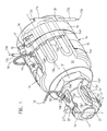
- Den Endabschnitt des Plastifizierzylinder mit Düse in perspektivischer Darstellung und im vertikalen Schnitt durch die Spritzachse,
- Fig. 3
- die Anordnung gemäß den Fign. 1,2 in Stirnansicht in vergrößerter Darstellung,
- Fig. 3a
- einen Ausschnitt aus der Anordnung gemäß Fig. 3,
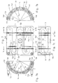
- Fig. 4
- einen Schnitt nach 4-4 von Fig. 2 (etwas verkleinert),
- Fig. 5
- zwei zu einer Manschette zusammengefügte Temperierschalen für den Plastifizierzylinder in Seitenansicht,
- Fig. 6
- eine Temperierschale gemäß Fig. 5 in Draufsicht,
- Fig. 7
- die Schale gemäß Fig. 6 bei abgenommenen Spannbändern in vergrößerter Darstellung,
- Fig. 7a,7b
- einen Schnitt durch die Schale gemäß Fig. 7 nach den Linien 7a-
7a und 7b-7b, - Fig. 7c
- die Schale gemäß Fig. 7 in Seitenansicht,
- Fig. 8-10
- eine für die Düse bestimmte Temperierschale in Stirn- und Innenansicht sowie in Draufsicht,
- Fig. 11
- das in eine Schale gemäß den Fign. 8-10 einzugießende Temperierelement,
- Fig. 12
- eine Variante der Heizeinrichtung in einer Darstellung entsprechend Fig. 2,
- Fig. 13-16
- die zur Variante gemäß Fig. 12 gehörende Temperierschale bzw. das zu dieser Variante gehörende Temperierelement in einer Darstellung entsprechend den Fign. 8-11,
- Fig. 17, 18
- zwei Varianten des Temperierelementes in schematisch dargestellten Abwicklungen,
- Fig. 19, 20
- eine schematisch dargestellte Gußform mit eingeklemmtem Temperierelement in Schnitten, welche den Schnitten 7a-
7a und 7b-7b durch die Temperierschale in Fig. 7 entsprechen und - Fig. 21; 22a, 22b
- Schematas zum Verfahren zur Herstellung der Temperiereinrichtung.
- Fig. 1,2
- The end section of the plasticizing cylinder with nozzle in perspective and in vertical section through the spray axis,
- Fig. 3
- the arrangement according to FIGS. 1,2 in front view in an enlarged view,
- Fig. 3a
- 3 shows a section of the arrangement according to FIG. 3,
- Fig. 4
- a section according to 4-4 of Fig. 2 (somewhat reduced),
- Fig. 5
- side view of two tempering trays joined together to form a sleeve,
- Fig. 6
- 5 in top view,
- Fig. 7
- 6 with the straps removed in an enlarged view,
- 7a, 7b
- 7 shows a section through the shell according to FIG. 7 along lines 7a-7a and 7b-7b,
- Fig. 7c
- 7 in side view,
- Fig. 8-10
- a temperature control bowl for the nozzle in front and inside view and in top view,
- Fig. 11
- that in a bowl according to FIGS. 8-10 thermostatic element to be poured in,
- Fig. 12
- 2 shows a variant of the heating device in a representation corresponding to FIG. 2,
- Fig. 13-16
- the tempering bowl belonging to the variant according to FIG. 12 or the tempering element belonging to this variant in a representation corresponding to FIGS. 8-11,
- 17, 18
- two variants of the temperature control element in schematically illustrated developments,
- 19, 20
- a schematically illustrated mold with a clamped temperature control element in sections which correspond to the cuts 7a-7a and 7b-7b through the temperature control shell in Fig. 7 and
- Fig. 21; 22a, 22b
- Schematic of the process for manufacturing the temperature control device.
Im zeichnerisch dargestellten Ausführungsbeispiel ist die Temperiereinrichtung am Plastifizierzylinder und an der Düse einer Kunststoff-Spritzgießmaschine dargestellt. Zunächst wird auf die Temperiereinrichtung am Plastifizierzylinder eingegangen: Wesentlicher Bestandteil der Temperiereinrichtung sind aus jeweils zwei Temperierschalen 14 aufgebaute Manschetten, welche den Plastifizierzylinder 10 umschließen. Entsprechend der Länge des Plastifizierzylinders 10 sind mehrere Manschetten auf dem Plastifizierzylinder 10 axial aneinandergereiht. Aus der Zeichnung ist nur die der Düse benachbarte Manschette ersichtlich. Die Schalen 14 weisen als Kontaktfläche 14g je eine innere Mantelfläche sowie einer zur Kontaktfläche etwa konzentrische äußere Mantelfläche auf. Die beiden Schalen 14 einer Manschette sind mit Hilfe von zwei lösbaren Spannbändern 15 auf die zu temperierende Mantelfläche aufpreßbar. In jeder Schale 14 ist ein einziges Temperierelement eingegossen, das aus einem linearen Rohr derart geformt ist, daß es mehrere Schleifen 13 je mit zwei linearen Abschnitten 13a und einem gebogenen Abschnitt 13b aufweist. Jede Schleife 13 liegt etwa symmetrisch zu einer Mantellinie c-c des Plastifizierzylinders 10. Jedes Temperierelement weist freie, d.h. vom Gußmetall unbedeckte Stützflächen 13e auf. An diesen münden Ausnehmungen 14e,14f (Fig. 7,7a-7c,9,14), die von der inneren und äußeren Mantelfläche der zugehörigen Schale 14 ausgehen. Das die Oberfläche des Temperierelementes bildende Metall ist zumindest im Bereich der Stützflächen 13e,13e′ in der elektrochemischen Spannungsreihe so hoch oder höher angesiedelt als das Metall, in welches das Temperierelement eingegossen ist. Die Schleifen 13 des mäanderartigen Temperierelementes sind in stumpfwinklig zueinander und senkrecht zu Radialen s-s des Plastifizierzylinders 10 stehenden Ebenen e-e (Fig. 3,4,7a,7b) angeordnet. Der in der Radialen s-s abgenommene Abstand z (Fig. 3a) des gebogenen Abschnittes 13b von der äußeren Mantelfläche ist um das mehrfache größer als der entsprechende Abstand p (Fig. 3a) von der inneren Mantelfläche. Wie insbesondere aus den Fign. 5 und 6 ersichtlich, sind die inneren Ausnehmungen 14e , welche sich von der inneren Mantelfläche der Schalen 14 her erstrecken gegenüber den äußeren Ausnehmungen 14f , welche sich von der äußeren Mantelfläche erstrecken, axial gegeneinander versetzt. Die Versetzungsstrecke r ist in den Fign. 6 und 7 erkennbar. Die rillenartigen Ausnehmungen 14e,14f sind in senkrecht zur Spritzachse b-b stehenden Ebenen y-y angeordnet. Die linearen Abschnitte 13a der Schleifen 13 grenzen je an wenigstens zwei innere und zwei äußere Ausnehmungen an. Die Spannbänder 15 sind mittels eines Spannbolzens 17 und mittels Lagerbolzen 16 spannbar. Bei der Montage sind die Spannbänder 15 an Anformungen 14d geführt bzw. axial festgelegt. In Umfangrichtung sind die Spannbänder mittels Arretierstiften 20 fixierbar. Die Fugen zwischen den beiden Schalen 14 der Manschetten liegen in einer horizontalen Ebene (Fugenebene t-t in Fig. 3,4). Die Anschlußenden 13c bzw. 13c˝ (Fig. 12) der Temperierelemente, die aus der Schale 14 herausgeführt sind, verlaufen jeweils senkrecht zur Fugenebene t-t. Wie insbesondere aus den Fign. 1 und 2 erkennbar, weist die jeweils obere Schale 14 einer Manschette eine Durchtrittsöffnung 22 für einen Thermofühler 18 auf. Der Thermofühler 18 ist durch eine Befestigungshohlschraube 19 gehalten, in welcher er mittels einer Spiralfeder axial verstellbar aufgenommen ist. Da ein Innengewinde der Befestigungshohlschraube 19′ in die Federspirale eingreift, kann durch Drehen der Befestigungshohlschraube 19′ die an einer Schulter des Thermofühlers 18 abgestützte Federspirale vorgespannt und dadurch der Thermofühler axial belastet werden.In the exemplary embodiment shown in the drawing, the temperature control device on the plasticizing cylinder and on the nozzle of a plastic injection molding machine is shown. The temperature control device on the plasticizing cylinder is first dealt with: An essential component of the temperature control device are sleeves constructed from two
Im folgenden wird die Temperiereinrichtung an der Düse beschrieben:The temperature control device on the nozzle is described below:
An dieser sind zwei Schalen 14' vorgesehen, die sich zu einer Manschette ergänzen. Die Manschette ist mittels eines einzigen Spannbandes 15' auf die Mantelfläche der Düse 11 aufgepreßt. Die Fugen 27 der beiden Schalen 14' liegen in einer vertikalen Ebene (Fugenebene t'-t' in Fig. 1,3). Die freien linearen Anschlußenden 13c' (Fig. 1-11 und 13''' in Fig. 12-16) verlaufen jeweils senkrecht zur Fugenebene t'-t'. Die beiden Temperierelemente weisen je eine einzige Schleife 13' auf (Fig. 8-11; 13-16). In der vertikalen Fuge 27 ist durch entsprechende Aussparungen an den Schalen 14' eine Durchtrittsöffnung 22' für einen Thermofühler 18 gebildet. Der Thermofühler 18 ist mittels eins Halteelementes 21' gehalten. Das Halteelement 21' ist Bestandteil des Spannbandes 15'. Der Thermofühler ist mittels einer Spirale axial belastbar. Im Ausführungsbeispiel einer Düse gemäß den Fign. 1 bis 11 weisen die Schalen Anformungen 14h' auf, welche an einer radialen Schulter 12b' einer Hohlschraube 12 anliegen. Mittels der Hohlschraube 12 ist der Düsenkörper mit dem Plastifizierzylinder 10 verbunden. Das Spannband 15' ist in einem vorderen Abschnitt der Düse vor der Hohl schraube 19' für den Thermofühler 18 angeordnet. Der gebogene Abschnitt 13b' liegt mit den beiden linearen Abschnitten 13a' in einer vertikalen Ebene. Wie aus Fig. 9,14 ersichtlich, sind die Ausnehmungen 14e',14f' zylindrische Kanäle.On this two shells 14 'are provided which complement each other to form a cuff. The sleeve is pressed onto the lateral surface of the
Im Ausführungsbeispiel gemäß den Fign. 12-16 ist das Spannband 15c' in einem rückwärtigen Abschnitt der Düse angeordnet und liegt daher im Bereich des Thermofühlers 18. Die Befestigungshohlschraube 19' durchgreift daher das Spannband 15' über eine Ausnehmung, die vorne und hinten von schmalen Stegen des Spannbandes 15' begrenzt ist, wie insbesondere aus den Fign. 13 bis 16 erkennbar, ist der gebogene Abschnitt 13b' des Temperierelementes aus der vertikalen Ebene, in welcher die linearen Abschnitte liegen, in Anpassung an den Radius des zylindrischen Düsenkörpers nach außen ausgebogen.In the exemplary embodiment according to FIGS. 12-16, the tensioning strap 15c 'is arranged in a rear section of the nozzle and is therefore located in the region of the
Während im Ausführungsbeispiel der Fign. 1-11 die Temperierelemente als Widerstandsheizelemente ausgebildet sind, zeigt das Ausführungsbeispiel der Fign. 12-16 Kühlrohre KR, die von einem Kühlmedium durchflossen sind. Das Kühlmedium wird über die freien Anschlußenden 13c'' der Kühlrohre der Schalen 14 am Plastifizierzylinder 10 bzw. über die freien Anschlußenden 13c''' des Kühlrohres KR an der Düse 11 zugeführt bzw. abgeleitet.While in the embodiment of FIGS. 1-11 the temperature control elements are designed as resistance heating elements, the embodiment of FIGS. 12-16 KR cooling tubes through which a cooling medium flows. The cooling medium is supplied or discharged via the free connection ends 13c '' of the cooling tubes of the
Figur 18 Zeigt eine Gestaltung der Schleifen mit der eine höhere Heizleistung pro Flächeneinheit erreicht werden kann, während Figur 17 eine Anordnung der Schleifen aufweist, die eine bevorzugte Übertragung der Heizleistung an bestimmten Stellen erlaubt. Auch in diesem Fall liegen die Schleifen 13 symmetrisch zu Mantellinien c-c. Durch eine Wendelung des Widerstandsdrahtes im Rohr 13f ist es möglich, die Heizleistung wesentlich zu erhöhen. In diesem Fall ergeben sich größere Durchmesser der Temperierelemente. In den freien Anschlußenden 13c,13c' der als Heizrohre ausgestalteten Temperierelemente wird keine Wärme erzeugt.FIG. 18 shows a design of the loops with which a higher heating power per unit area can be achieved, while FIG. 17 has an arrangement of the loops which allows a preferred transfer of the heating power at certain points. In this case, too, the
Im folgenden wird das Verfahren zur Herstellung der Temperier - schalen anhand der Figuren 19-22 erläutert. In der schematisch dargestellten Gießform gemäß den Fig. 19, 20 befinden sich die Schnitte in einem Abstand voneinander, welcher dem Abstand r in den Fign. 6 und 7c entspricht. Demzufolge liegen die Schnitte in Ebenen, die den Ebenen y-y der Husnehmungen 14f und 14e in der fertigen Temperierschale gemäß den Fign. 7a und 7b entsprechen. Demzufolge sind in Fig. 19 nur die an den innenseitigen Stützflächen 13e und in Fig. 20 nur die an den außenseitigen Stützflächen 13f des Temperierelements angreifenden rippenartigen Ausformungen 40a',40b' erkennbar. Jede rippenartige Ausformung 40a',40b' erstreckt sich mit einem der späteren Temperierschale entsprechenden Radius halbkreisförmig an der den Formhohlraum begrenzenden Wand der Formhälften 40a,40b. Es ist jedoch auch möglich, die rippenartige Ausformung abschnittsweise zu unterbrechen. In diesem Falle verbleiben lediglich einzelne Stützzapfen als "Ausformungen".In the following the method for the production of the temperature control shells is explained with reference to FIGS. 19-22. 19, 20, the cuts are at a distance from one another which corresponds to the distance r in the FIGS. 6 and 7c. As a result, the cuts lie in planes which correspond to the planes yy of the
In den Fign. 21,22a,22b sind die Verfahrensschritte zur Herstellung der Temperierelemente anhand von Schematas verdeutlicht, welche einzelne Verfahrensstände VA; VB; VC; VD; VE VF im Verfahren darstellen. In den Verfahrensständen VA, VC und VE ist das schematisch dargestellte Temperierelement je in Stirnansicht und in Seitenansicht gezeigt. Das gleiche gilt für die Verfahrensstände VA, VB, VC und VD in Fig. 22a,22bIn Figs. 21, 22a, 22b illustrate the process steps for producing the temperature control elements on the basis of schematics, which individual process statuses VA; VB; VC; VD; Represent VE VF in the procedure. In the process stages VA, VC and VE, the temperature control element shown schematically is shown in front view and in side view. The same applies to the process states VA, VB, VC and VD in FIGS. 22a, 22b
Für das Verfahren gilt im einzelnen: Potentielle, rohrartige und lineare Temperierelemente, also Heizrohre oder Kühlrohre werden unter Bildung einer oder mehrerer Schleifen 13, die je einen gebogenen Abschnitt 13b und zwei lineare Abschnitte 13a aufweisen zu mäanderartigen Temperierelementen verformt. Sodann werden diese Temperierelemente je in eine Gußform 40 zwischen Ausformungen 40a' und 40b' der Formhälften 40a,40b einer Gußform festgeklemmt, weiche Ausformungen 40a',40b' in den Formhohlraum 41 hineinragen und auf Stützflächen 13e des Temperierelementes angreifen. Sodann wird das flüssige Metall, vorzugsweise Aluminium bei einem Einspritzdruck zwischen 5·10⁷ bis 13·10⁷ Pa (500 bis 1300 bar) in einer Zeitspanne von höchstens sechs Sekunden in den Formhohlraum 41 eingespritzt. Der Einspritzvorgang kann auch auf den Bruchteil einer Sekunde beschränkt werden, wenn entsprechend gestalterische Voraussetzungen des Formhohlraumes 41 und des darin festgeklemmten mäanderartigen Temperierelementes vorliegen.The following applies to the method in detail: Potential, tube-like and linear temperature control elements, that is to say heating tubes or cooling tubes, are deformed into meandering temperature control elements to form one or
In den Ansprüchen 8 und 9 sind zwei unterschiedliche Verfahren niedergelegt, die jedoch gleichermaßen zu Temperierschalen führen.In claims 8 and 9, two different methods are laid down, which, however, lead equally to tempering dishes.
Der Verfahrensabschnitt zur Herstellung eines mäanderartigen Temperierelementes (Anspruch 8 - Fig. 21) umfaßt folgende Verfahrensschritte:
- 1. Ein (marktübliches) lineares, rohrartiges Temperierelement wird um seine Achse (Drehachse f-f) drehbar und axial in eine Verschieberichtung V verschiebbar gehaltert.
- 2. Das so gehalterte Temperierelement wird an einem freien Ende unter Bildung einer ersten Schleife 13 mittels einer
Biegeeinrichtung 25 in einer bestimmten Richtung (Biegerichtung B) um 180° umgebogen.
(Nach diesen beiden Verfahrensschritten ist der in Fig. 21 unter "VA" dargestellte Verfahrensstand erreicht). - 3. Das an einem Ende verformte Temperierelement wird in der Drehachse f-f um die Länge einer Schleife in Verschieberichtung V axial verschoben und um einen Zentriwinkel von 180° plus einem spitzen Winkel Alpha (Fig. 3) um die Drehachse f-f entgegen dem Uhrzeigersinn gedreht, wobei der Winkel Alpha zwischen den Ebenen e-e in Fig. 3,4,7a,7b benachbarter Schleifen gebildet ist. (Nun ist der Verfahrensstand VB in Fig. 21 erreicht).
- 4. Das verformte Ende des Temperierelements wird zusammen mit der ersten Schleife 13 unter Bildung einer zweiten Schleife 13' in der Biegerichtung B um 180° umgebogen (Verfahrensstand VC in Fig. 21).
- 5. Das so verformte Temperierelement wird in der Drehachse f-f erneut um die Länge einer Schleife axial verschoben und um einen Zentriwinkel von 180° plus dem Winkel Alpha um die Drehachse f-f im Uhrzeigersinn gedreht (Verfahrensstand VD in Fig. 21).
- 6. Das Ende des Temperierelements wird mit der angeformten ersten 13 und zweiten Schleife 13' unter Bildung einer dritten Schleife 13'' mit Hilfe der Biegeeinrichtung um 180° umgebogen (Verfahrensstand VE in Fig. 21).
- 7. Das so verformte Temperierelement wird um die
Länge einer Schleife 13 erneut axial verschoben und um einen Zentriwinkel von 180° plus dem Winkel Alpha um die Drehachse f-f gedreht (Verfahrensstand VF in Fig. 21). - 8. Das Temperierelement wird am verformten Ende zusammen mit der ersten 13, zweiten 13' und dritten Schleife 13'' unter Bildung einer vierten Schleife 13''' in der Biegerichtung B umgebogen.
- 1. A (commercially available) linear, tubular tempering element is rotatably supported about its axis (axis of rotation ff) and axially displaceable in a direction of displacement V.
- 2. The temperature control element held in this way is bent at a free end to form a
first loop 13 by means of abending device 25 in a certain direction (bending direction B) by 180 °.
(After these two process steps, the process status shown in FIG. 21 under "VA" is reached). - 3. The tempering element deformed at one end is axially displaced in the axis of rotation ff by the length of a loop in the direction of displacement V and rotated counterclockwise about the axis of rotation ff by a central angle of 180 ° plus an acute angle alpha (FIG. 3), whereby the angle alpha is formed between the planes ee in FIGS. 3, 4, 7a, 7b of adjacent loops. (Process status VB in FIG. 21 has now been reached).
- 4. The deformed end of the temperature control element is bent together with the
first loop 13 to form a second loop 13 'in the bending direction B by 180 ° (process status VC in FIG. 21). - 5. The temperature control element deformed in this way is axially displaced again in the axis of rotation ff by the length of a loop and rotated clockwise by a central angle of 180 ° plus the angle alpha about the axis of rotation ff (process status VD in FIG. 21).
- 6. The end of the temperature control element is bent with the molded-on first 13 and second loop 13 'to form a third loop 13''by means of the bending device by 180 ° (process status VE in FIG. 21).
- 7. The temperature control element deformed in this way is again axially displaced by the length of a
loop 13 and rotated by a central angle of 180 ° plus the angle alpha about the axis of rotation ff (process status VF in FIG. 21). - 8. The temperature control element is bent at the deformed end together with the first 13, second 13 'and third loop 13''to form a fourth loop 13''' in the bending direction B.
Das Verfahren kann zur Anfügung weiterer Schleifen im Sinne der bisherigen Verfahrensschritte weitergeführt werden, wobei bei jedem weiteren Verfahrensschritt mit Drehung um die Drehachse f-f jeweils die Drehrichtung gewechselt wird.The method can be continued to add further loops in the sense of the previous method steps, with the direction of rotation being changed in each further method step with rotation about the axis of rotation f-f.
Die Variante des Verfahrensabschnittes zur Herstellung eines mäanderartigen Temperierelementes gemäß Anspruch 9 (Fig. 22a;22b) umfaßt folgende Verfahrensschritte:
- a) Ein (marktübliches), lineares, rohrartiges Temperierelement wird in einer Haltevorrichtung H, die um eine Drehachse s-s drehbar und in dieser Drehachse in einander entgegengesetzten Richtungen (Verschieberichtung nach rechts Vr oder Verschieberichtung nach links Vl) axial verschiebbar ist, exzentrisch zur Drehachse s-s gehaltert, wobei es in biegebereiter Position in einer stationären Biegevorrichtung 25 aufgenommen ist.
- b) Das so gehalterte Temperierelement wird an einem Ende unter Bildung einer ersten Schleife 13 mittels der Biegeeinrichtung 25 in einer Biegeebene B' um 180° umgebogen (Verfahrensstand VA in Fig. 22a).
- c) Das so teilweise verformte Temperierelement wird zusammen mit der Halteeinrichtung in der einen Verschieberichtung (Verschieberichtung nach rechts Vr) parallel zur Drehachse s-s etwa um die
Länge einer Schleife 13 verschoben und im Gefolge einer Drehung mit der Haltevorrichtung H um die Drehachse s-s um einen Zentriwinkel Alpha′ derart auf einer Kreislinie K bewegt, daß der noch nicht verformte lineare Abschnitt 13n des Temperierelementes in biegebereiter Positionvon der Biegevorrichtung 25 aufgenommen ist. - d) Das Temperierelement wird am unverformten Ende in der Biegeebene B′ unter Bildung einer zweiten Schleife 13′ um 180° in einer Richtung umgebogen, welcher der Biegerichtung bei Bildung der ersten Schleife 13 entgegengesetzt ist (Verfahrensstand VB in Fig. 22a).
- e) Das so verformte Temperierelement wird zusammen mit der Haltevorrichtung in der entgegengesetzten Verschieberichtung (Verschieberichtung nach links Vl) etwa um die Länge einer Schleife parallel zur Drehachse s-s verschoben und im Gefolge einer Drehung mit der Haltevorrichtung um die Drehachse s-s um einen Zentriwinkel Alpha′ derart auf einer Kreislinie K bewegt, daß sein noch nicht verformter,
linearer Abschnitt 13n in biegebereiter Positionvon der Biegevorrichtung 25 aufgenommen ist. - f) Das Temperierelement wird am unverformten Ende in der Biegeebene B′ unter Bildung einer dritten Schleife 13˝ um 180° in einer Richtung umgebogen, welche der Biegerichtung bei Bildung der zweiten Schleife 13′ entgegengesetzt ist (Verfahrensstand VC in Fig. 22b).
- g) Das so verformte Temperierelement wird zusammen mit der Haltevorrichtung H in einer Verschieberichtung, die der Verschieberichtung bei Bildung der letzten Schleife 13 entgegengesetzt ist (Verschieberichtung Vr) um etwa die Länge einer Schleife erneut parallel zur Drehachse s-s verschoben und im Gefolge einer Drehung mit der Haltevorrichtung um die Drehachse s-s um einen Zentriwinkel Alpha′ derart auf einer Kreislinie K bewegt, daß sein noch nicht verformter, linearer Abschnitt in biegebereiter Position von der stationären Biegevorrichtung 25 aufgenommen ist.
- h) Das Temperierelement wird am unverformten Ende in der Biegeebene B′ unter Bildung einer vierten Schleife 13‴ in einer Biegerichtung umgebogen, welche der Biegerichtung bei Bildung der zweiten Schleife 13′ entspricht (Verfahrensstand VD in Fig. 22b).
- a) A (commercially available), linear, tube-like temperature control element becomes eccentric to the axis of rotation ss in a holding device H, which can be rotated about an axis of rotation ss and axially in this direction of rotation in opposite directions (direction of displacement to the right Vr or direction of displacement to the left Vl) supported, wherein it is received in a ready-to-bend position in a
stationary bending device 25. - b) The temperature control element held in this way is bent at one end to form a
first loop 13 by means of thebending device 25 in a bending plane B 'by 180 ° (process status VA in FIG. 22a). - c) The thus partially deformed temperature control element is displaced together with the holding device in one displacement direction (displacement direction to the right Vr) parallel to the axis of rotation ss approximately by the length of a
loop 13 and in the course of a rotation with the holding device H around the axis of rotation ss a center angle alpha 'moves on a circular line K such that the non-deformedlinear section 13n of the temperature control element is received in the bending-ready position by the bendingdevice 25. - d) The temperature control element is bent at the undeformed end in the bending plane B 'to form a second loop 13' by 180 ° in a direction which is opposite to the bending direction when the
first loop 13 is formed (process status VB in Fig. 22a). - e) The temperature control element thus deformed is shifted together with the holding device in the opposite direction of displacement (shifting direction to the left Vl) approximately by the length of a loop parallel to the axis of rotation ss and as a result of a rotation with the holding device about the axis of rotation ss by a central angle Alpha 'in such a way moved on a circular line K that its not deformed,
linear section 13n is received in the bending-ready position by the bendingdevice 25. - f) The temperature control element is bent at the undeformed end in the bending plane B 'to form a third loop 13' by 180 ° in a direction which is opposite to the bending direction when the second loop 13 'is formed (process status VC in FIG. 22b).
- g) The temperature control element thus deformed is moved together with the holding device H in a direction of displacement that is opposite to the direction of displacement when the
last loop 13 is formed (direction of displacement Vr) by approximately the length of a loop again parallel to the axis of rotation ss and as a result of a rotation with the Holding device about the axis of rotation ss about a central angle Alpha 'moved on a circular line K such that its not deformed, linear portion is received in the bending-ready position by thestationary bending device 25. - h) The temperature control element is bent at the undeformed end in the bending plane B 'to form a
fourth loop 13 ‴ in a bending direction which corresponds to the bending direction when the second loop 13' is formed (process status VD in Fig. 22b).
Für das Biegeverfahren ist charakteristisch, daß eine stationäre Biegevorrichtung 25 in einer einzigen Biegeebene B′ wechselweise nach der einen und der anderen Seite biegt und daß das jeweils noch nicht verformte, mehr oder weniger lange, freie Ende des Temperierelementes taktweise in biegebereite Position in die Biegevorrichtung 25 eingefahren wird. Letzteres geschieht dadurch, daß eine Haltevorrichtung H in ihrer Drehachse s-s wechselweise in der einen oder anderen Richtung etwa um die Länge einer Schleife axial verschoben und jeweils um einen Zentriwinkel Alpha′ gedreht wird, wobei sich das in der Haltevorrichtung H exzentrisch gehaltene Temperierelement auf einer Kreislinie bewegt.It is characteristic of the bending process that a
Der Winkel Alpha ist derjenige spitze Winkel, der zwischen den Ebenen e-e zweier benachbarter Schleifen des fertigen Temperierelementes gebildet ist (Fig. 3; 22a,22b). Die Größe des Zentriwinkels Alpha′ ist abhängig von der Anzahl der Schleifen des Temperierelementes.The angle alpha is the acute angle that is formed between the planes e-e of two adjacent loops of the finished temperature control element (FIGS. 3; 22a, 22b). The size of the center angle Alpha 'depends on the number of loops of the temperature control element.
Claims (9)
- Temperature control arrangement on a plasticising cylinder (10), which is provided with a nozzle (11), of a machine which processes plastics materials, including cast metal shells (14;14'), which each have an inner surface as the contact face (14g) and an outer surface which is substantially concentric relative to the contact face (14g), and said shells can be pressed onto the surface to be temperature-controlled of the plasticising cylinder (10), or respectively of the nozzle (11), by means of tensioning bands (15), two respective shells (14;14') being combined to form a sleeve, which surrounds the surface to be temperature-controlled, and including temperature control means, which are incorporated in the shells (14;14') and moulded from linear pipes in such a manner that they each have at least one loop (13) with two linear portions (13a) and one curved portion (13b), which loop lies substantially symmetrically relative to a generatrix (c-c) of the plasticising cylinder (10), serpentine-like temperature control means being provided on the plasticising cylinder (10) and each having a plurality of loops (13), which are disposed in planes (e-e) which extend at obtuse angles relative to one another and perpendicularly relative to the radial (s-s) of the plasticising cylinder, characterised in that only one single temperature control means is incorporated in each of the shells (14;14') and has supporting faces (13e, 13e'), which are free of the cast metal (not covered by the cast metal), recesses (14e,14f;14e',14f') terminating at said supporting faces and extending from the inner and outer surfaces of the shells (14;14'), the spacing (z) between the curved portion (13b) of the loop (13) and the outer surface, when measured with respect to the radial (s-s), being greater than the corresponding spacing (p) between said portion and the inner surface.
- Temperature control arrangement according to claim 1, characterised in that the metal, forming the surface of the temperature control means, is established in the electrochemical series, at least in the region of the supporting faces (13e;13e'), to be as high as, or higher than, the metal in which the temperature control means is incorporated.
- Temperature control arrangement according to claim 1 or 2, characterised in that inner recesses (14e;14e'), which extend from the inner surface of the shells (14;14'), are axially offset from one another compared with outer recesses (14f;14f'), which extend from the outer surface, the linear portions (13a) of the loops (13) at the plasticising cylinder (10) each abutting against at least two inner and two outer recesses .
- Temperature control arrangement according to one of the preceding claims, characterized in that the joints (26) between the two shells (14) of the sleeves on the plasticising cylinder (10) lie in a horizontal joint plane (t-t), and the joints (27) of the two shells (14') of the sleeve at the nozzle (11) lie in a vertical joint plane (t'-t'), the free, linear connecting ends (13c,13c',13c'',13c''') of the temperature control means each extending perpendicularly relative to the joint plane (t-t;t'-t').
- Temperature control arrangement according to one of the preceding claims, characterised in that the two temperature control means at the nozzle (11) each have a single loop (13').
- Temperature control arrangement according to one of claims 4 or 5, characterised in that a through-aperture (22') for a thermocouple (18') is formed in the vertical joint (27) at the nozzle (11) by corresponding recesses in the shells (14'), and said thermocouple is retained by means of a retaining element (21'), which is traversed by a tensioning bolt (17') and mounted on a tensioning band (15'), and by means of a hollow securing screw (19'), and is axially adjustable.
- Temperature control arrangement according to one of the preceding claims, characterised in that the two identical shells (14') at the nozzle (11) each have a moulded-on portion (14k'), which protrudes inwardly over their contact face (14g') and engages behind a vertical shoulder of the nozzle (11).
- Method of producing shells (14) for a temperature control arrangement on the plasticising cylinder according to one of claims 1 to 4, wherein potential, tubular, linear temperature control means are deformed into serpentine-like temperature control means so as to form a plurality of loops (13), which each have a curved portion (13b) and two linear portions (13a), in that a linear, potential temperature control means is mounted so as to be rotatable about its axis to form an axis of rotation (f-f) and so as to be axially displaceable in a displacement direction (V) and is bent at a free end through 180° in a predetermined bending direction (B) by means of a bending arrangement (25) so as to form a first loop (13), and in that the temperature control means, which is deformed at one end, is then axially displaced in the displacement direction (V) with respect to the axis of rotation (f-f) for a distance corresponding to the length of a loop and rotated in a clockwise or anti-clockwise direction about the axis of rotation (f-f) through a sector angle of 180°, plus an acute angle alpha, which is formed between the planes (e-e) of adjacent loops, and in that the deformed end of the temperature control means, together with the first loop (13), is then bent through 180° in the bending direction (B) so as to form a second loop (13'), and in that the temperature control means, which is thus deformed, is then axially displaced again with respect to the axis of rotation (f-f) for a distance corresponding to the length of a loop and rotated in an anti-clockwise or clockwise direction about the axis of rotation (f-f) through a sector angle of 180°, plus the angle alpha, and in that the end of the temperature control means having the moulded-on first loop (13) and second loop (13') is bent through 180° by means of the bending arrangement (25) so as to form a third loop (13''), and so on, then these temperature control means are cast in metal by means of casting moulds (40), the hollow configuration of each mould corresponding to a shell (14), the serpentine-like temperature control means being fixedly clamped in the casting mould (40) between projection members (40a',40b') of the mould halves (40a,40b), which projection members protrude into the mould cavity (41) and co-operate with the temperature control means in regions of diametrical supporting faces (13e), and then the fluid metal is injected into the mould cavity (41) at an injection pressure of between 5.10⁷ and 13.10⁷ Pa (between 500 and 1300 bar) in a maximum time interval of six seconds.
- Method of producing shells (14) for a temperature control arrangement on the plasticising cylinder according to one of claims 1 to 4, wherein potential, tubular, linear temperature control means are deformed into serpentine-like temperature control means so as to form a plurality of loops (13), which each have a curved portion (13b) and two linear portions (13a), in which the following method steps are effected:
a linear, tubular temperature control means is mounted in a retaining frame (H) eccentrically relative to the axis of rotation (s-s), which frame is rotatable about an axis of rotation (s-s) and is axially displaceable in oppositely orientated directions (Vr,Vl) with respect to this axis of rotation, said temperature control means being accommodated in a stationary bending arrangement (25) in a position ready for bending;
the temperature control means, which is thus mounted, is bent at one end through 180° in a bending plane (B') by means of the bending arrangement (25) so as to form a first loop (13);
the temperature control means, which is thus partially deformed, is displaced together with the retaining means in one displacement direction (Vr) parallel to the axis of rotation (s-s) for a distance substantially corresponding to the length of a loop (13) and, as a result of a rotation with the retaining means (H) about the axis of rotation (s-s) through a sector angle (alpha'), is moved along a circular line K) in such a manner that the linear portion (13n) of the temperature control means, which has not yet been deformed, is received by the bending arrangement (25) in a position ready for bending;
at the non-deformed end, the temperature control means is bent through 180° in the bending plane (B') in a direction which is opposite the bending direction used to form the first loop (13) so as to form a second loop (13');
the temperature control means, thus deformed, is displaced, together with the retaining means, in the oppositely orientated displacement direction (Vl) parallel to the axis of rotation (s-s) for a distance substantially corresponding to the length of a loop and, as a result of a rotation with the retaining means about the axis of rotation (s-s) through a sector angle (alpha'), is moved along a circular line (K) in such a manner that its linear portion (13n), which has not yet been deformed, is received by the bending arrangement in a position ready for bending;
at the non-deformed end, the temperature control means is bent through 180° in the bending plane (B') in a direction which is opposite the bending direction used to form the second loop (13') so as to form a third loop (13'');
these temperature control means are then cast in metal by means of casting moulds (40), the hollow configuration of each mould corresponding to a shell (14), the serpentine-like temperature control means being fixedly clamped in the casting mould (40) between projection members (40a',40b') of the mould halves (40a,40b), which projection members protrude into the mould cavity (41) and co-operate with the temperature control means in regions of diametrical supporting faces (13e), and then the fluid metal is injected into the mould cavity (41) at an injection pressure of between 5.10⁷ and 13.10⁷ Pa (between 500 and 1300 bar) in a maximum time interval of six seconds.
Applications Claiming Priority (4)
| Application Number | Priority Date | Filing Date | Title |
|---|---|---|---|
| DE3914742 | 1989-05-05 | ||
| DE3914742 | 1989-05-05 | ||
| EP89115780 | 1989-08-26 | ||
| EP89115780 | 1989-08-26 |
Publications (3)
| Publication Number | Publication Date |
|---|---|
| EP0396030A2 EP0396030A2 (en) | 1990-11-07 |
| EP0396030A3 EP0396030A3 (en) | 1991-12-04 |
| EP0396030B1 true EP0396030B1 (en) | 1995-08-16 |
Family
ID=25880574
Family Applications (1)
| Application Number | Title | Priority Date | Filing Date |
|---|---|---|---|
| EP90108018A Expired - Lifetime EP0396030B1 (en) | 1989-05-05 | 1990-04-27 | Heating apparatus for a machine for working plastic materials |
Country Status (6)
| Country | Link |
|---|---|
| US (1) | US5157241A (en) |
| EP (1) | EP0396030B1 (en) |
| JP (1) | JP2795966B2 (en) |
| AT (1) | ATE126474T1 (en) |
| CA (1) | CA2015886C (en) |
| DE (1) | DE59009524D1 (en) |
Families Citing this family (7)
| Publication number | Priority date | Publication date | Assignee | Title |
|---|---|---|---|---|
| US5459811A (en) * | 1994-02-07 | 1995-10-17 | Mse, Inc. | Metal spray apparatus with a U-shaped electric inlet gas heater and a one-piece electric heater surrounding a nozzle |
| DE4404031C1 (en) * | 1994-02-09 | 1995-01-19 | Werner & Pfleiderer | Barrel section with electrical heating elements for a twin-screw extruder |
| AT503222B1 (en) * | 2006-01-30 | 2008-07-15 | Smk Metall U Kunststoffwaren G | HEATING AND COOLING DEVICE |
| JP2008120417A (en) * | 2006-11-10 | 2008-05-29 | Koyo Autom Mach Co Ltd | Labelling machine |
| US8395096B2 (en) * | 2009-02-05 | 2013-03-12 | Sandvik Thermal Process, Inc. | Precision strip heating element |
| US10596759B2 (en) * | 2017-10-25 | 2020-03-24 | Chromalox, Inc. | Extrusion assembly for an additive manufacturing system |
| JP6867360B2 (en) * | 2018-12-10 | 2021-04-28 | リョービ株式会社 | Die casting parts |
Family Cites Families (17)
| Publication number | Priority date | Publication date | Assignee | Title |
|---|---|---|---|---|
| US2851082A (en) * | 1954-03-01 | 1958-09-09 | Reynolds Metals Co | Apparatus for making serpentine tube heat exchanger by twisting one or more runs |
| DE1149161B (en) * | 1959-12-18 | 1963-05-22 | Kloeckner Humboldt Deutz Ag | Pipe jacket heater for screw extrusion for processing thermoplastics |
| US3370262A (en) * | 1963-05-27 | 1968-02-20 | Sprague Electric Co | Electrical resistor |
| US3317958A (en) * | 1964-08-17 | 1967-05-09 | Nrm Corp | Extruder |
| US3730262A (en) * | 1971-08-06 | 1973-05-01 | Emerson Electric Co | Heating and cooling units |
| DE2236898A1 (en) * | 1972-07-27 | 1974-02-07 | Stiebel Eltron Gmbh & Co Kg | Bending tubes for heat exchangers - using machine with two grooved bending rolls side by side |
| US3933200A (en) * | 1974-06-21 | 1976-01-20 | Emerson Electric Co. | Temperature conditioning means |
| US4112728A (en) * | 1975-08-22 | 1978-09-12 | Deutsche Babcock Aktiengesellschaft | Device for bending pipes |
| GB1520326A (en) * | 1976-04-28 | 1978-08-09 | Hedin Ltd | Mounting electric resistance heating elements |
| JPS58148740A (en) * | 1982-02-27 | 1983-09-03 | Fujikura Ltd | Controlling method for resin temperature at plastic molding machine |
| JPS58136315U (en) * | 1982-03-10 | 1983-09-13 | 日本リプロマシン工業株式会社 | Thermoplastic synthetic resin foam waste recycling machine |
| DE3428539A1 (en) * | 1984-08-02 | 1986-02-13 | Heinz 7203 Fridingen Stegmeier | Heating collar |
| PL149289B1 (en) * | 1985-06-24 | 1990-01-31 | Akad Rolniczo Tech | Electric heater,especially for machines and equipment for processing of plastics |
| US4730937A (en) * | 1985-12-31 | 1988-03-15 | Karl Hehl | Plasticizing unit for an injection molding machine |
| IT1189089B (en) * | 1986-04-18 | 1988-01-28 | Gaetano Piazzola | HEAT EXCHANGER WITH MODULAR ELEMENTS, PARTICULARLY DESIGNED FOR EXTRUSION CYLINDERS, INJECTION PRESSES, DRAWING MACHINES AND SIMILAR MACHINES FOR THE PROCESSING OF PLASTIC MATERIALS |
| US4828020A (en) * | 1986-08-15 | 1989-05-09 | Crompton & Knowles Corporation | Internal finned heater-cooler for an extruder barrel |
| DE3736612C2 (en) * | 1987-10-29 | 1996-08-14 | Hotset Corp | Device for fastening spiral tubes on the spray nozzles of injection molds |
-
1990
- 1990-04-27 EP EP90108018A patent/EP0396030B1/en not_active Expired - Lifetime
- 1990-04-27 DE DE59009524T patent/DE59009524D1/en not_active Expired - Fee Related
- 1990-04-27 AT AT90108018T patent/ATE126474T1/en not_active IP Right Cessation
- 1990-05-03 CA CA002015886A patent/CA2015886C/en not_active Expired - Fee Related
- 1990-05-04 US US07/519,139 patent/US5157241A/en not_active Expired - Lifetime
- 1990-05-07 JP JP2115939A patent/JP2795966B2/en not_active Expired - Lifetime
Also Published As
| Publication number | Publication date |
|---|---|
| DE59009524D1 (en) | 1995-09-21 |
| CA2015886C (en) | 1998-06-23 |
| US5157241A (en) | 1992-10-20 |
| EP0396030A2 (en) | 1990-11-07 |
| JP2795966B2 (en) | 1998-09-10 |
| ATE126474T1 (en) | 1995-09-15 |
| EP0396030A3 (en) | 1991-12-04 |
| CA2015886A1 (en) | 1990-11-05 |
| JPH02305617A (en) | 1990-12-19 |
Similar Documents
| Publication | Publication Date | Title |
|---|---|---|
| DE3239807C2 (en) | Device for injection molding, in particular of precision castings without sprue | |
| EP0790079B1 (en) | method for producing a dispenser or the like | |
| EP0301189B1 (en) | Method and apparatus for manufacturing a ribbed plastic pipe | |
| DE3237799C2 (en) | ||
| DE2821333C2 (en) | Forming head for the production of a composite pipe made of thermoplastic material | |
| EP1979151B1 (en) | Improved neck block cooling | |
| DE10213798A1 (en) | Elongated plastic component molding method for production of rollers involves injection of melt through pin gates to a cylindrical chamber and an annular film gate to a annular cavity | |
| EP0396030B1 (en) | Heating apparatus for a machine for working plastic materials | |
| DE2939020C2 (en) | Preform for blow molding a flat plastic bottle | |
| DE2839552B2 (en) | Nozzle head for the production of plastic granulate | |
| EP0261523A2 (en) | Method for making an injection moulding tool | |
| WO2005108044A1 (en) | Injection mold | |
| DE3935856C1 (en) | ||
| DE60037529T2 (en) | DEVICE FOR CONTINUOUS EXTRUSION | |
| EP0464411B1 (en) | Apparatus for the manufacture of plastic pipes | |
| DE4141393A1 (en) | Injection moulding plastic tube extending in more than two direction - where core parts are injected first, then assembled by interlocking and second plastic layer is injected around outside | |
| DE3810528A1 (en) | DEVICE FOR EXTRUSION BLOW MOLDING DIVIDED CONTAINERS USING DOUBLE-COOLED BLOWING NEEDLES | |
| DE4013538A1 (en) | Thermal control for extruder barrel | |
| DE19724857C1 (en) | Rapid production of large-diameter, cut lengths of corrugated plastic tubing | |
| DE8129947U1 (en) | MULTIPLE INJECTION MOLD | |
| DE3036052C2 (en) | Device for producing a ball socket | |
| DE4442667A1 (en) | Die casting device with vertical heated sprues | |
| DE2500185C2 (en) | Blow molding machine | |
| DE2354134A1 (en) | DISTRIBUTOR FOR INJECTION MOLDING THERMO-SENSITIVE PLASTICS IN MULTIPLE MOLD TOOLS | |
| WO2001007227A1 (en) | Method for producing a hollow body using the lost core technology |
Legal Events
| Date | Code | Title | Description |
|---|---|---|---|
| PUAI | Public reference made under article 153(3) epc to a published international application that has entered the european phase |
Free format text: ORIGINAL CODE: 0009012 |
|
| AK | Designated contracting states |
Kind code of ref document: A2 Designated state(s): AT CH DE ES FR GB IT LI NL |
|
| 17P | Request for examination filed |
Effective date: 19910716 |
|
| PUAL | Search report despatched |
Free format text: ORIGINAL CODE: 0009013 |
|
| AK | Designated contracting states |
Kind code of ref document: A3 Designated state(s): AT CH DE ES FR GB IT LI NL |
|
| 17Q | First examination report despatched |
Effective date: 19940603 |
|
| GRAA | (expected) grant |
Free format text: ORIGINAL CODE: 0009210 |
|
| AK | Designated contracting states |
Kind code of ref document: B1 Designated state(s): AT CH DE ES FR GB IT LI NL |
|
| PG25 | Lapsed in a contracting state [announced via postgrant information from national office to epo] |
Ref country code: ES Free format text: THE PATENT HAS BEEN ANNULLED BY A DECISION OF A NATIONAL AUTHORITY Effective date: 19950816 |
|
| REF | Corresponds to: |
Ref document number: 126474 Country of ref document: AT Date of ref document: 19950915 Kind code of ref document: T |
|
| REF | Corresponds to: |
Ref document number: 59009524 Country of ref document: DE Date of ref document: 19950921 |
|
| GBT | Gb: translation of ep patent filed (gb section 77(6)(a)/1977) |
Effective date: 19950904 |
|
| ITF | It: translation for a ep patent filed |
Owner name: CALVANI SALVI E VERONELLI S.R.L. |
|
| ET | Fr: translation filed | ||
| PLBE | No opposition filed within time limit |
Free format text: ORIGINAL CODE: 0009261 |
|
| STAA | Information on the status of an ep patent application or granted ep patent |
Free format text: STATUS: NO OPPOSITION FILED WITHIN TIME LIMIT |
|
| 26N | No opposition filed | ||
| PGFP | Annual fee paid to national office [announced via postgrant information from national office to epo] |
Ref country code: NL Payment date: 19970429 Year of fee payment: 8 |
|
| PG25 | Lapsed in a contracting state [announced via postgrant information from national office to epo] |
Ref country code: NL Free format text: LAPSE BECAUSE OF NON-PAYMENT OF DUE FEES Effective date: 19981101 |
|
| NLV4 | Nl: lapsed or anulled due to non-payment of the annual fee |
Effective date: 19981101 |
|
| REG | Reference to a national code |
Ref country code: GB Ref legal event code: IF02 |
|
| PGFP | Annual fee paid to national office [announced via postgrant information from national office to epo] |
Ref country code: GB Payment date: 20020403 Year of fee payment: 13 |
|
| PGFP | Annual fee paid to national office [announced via postgrant information from national office to epo] |
Ref country code: FR Payment date: 20020416 Year of fee payment: 13 |
|
| PG25 | Lapsed in a contracting state [announced via postgrant information from national office to epo] |
Ref country code: GB Free format text: LAPSE BECAUSE OF NON-PAYMENT OF DUE FEES Effective date: 20030427 |
|
| GBPC | Gb: european patent ceased through non-payment of renewal fee | ||
| PG25 | Lapsed in a contracting state [announced via postgrant information from national office to epo] |
Ref country code: FR Free format text: LAPSE BECAUSE OF NON-PAYMENT OF DUE FEES Effective date: 20031231 |
|
| REG | Reference to a national code |
Ref country code: FR Ref legal event code: ST |
|
| PGFP | Annual fee paid to national office [announced via postgrant information from national office to epo] |
Ref country code: AT Payment date: 20050421 Year of fee payment: 16 |
|
| PGFP | Annual fee paid to national office [announced via postgrant information from national office to epo] |
Ref country code: DE Payment date: 20060413 Year of fee payment: 17 |
|
| PGFP | Annual fee paid to national office [announced via postgrant information from national office to epo] |
Ref country code: CH Payment date: 20060425 Year of fee payment: 17 |
|
| PG25 | Lapsed in a contracting state [announced via postgrant information from national office to epo] |
Ref country code: AT Free format text: LAPSE BECAUSE OF NON-PAYMENT OF DUE FEES Effective date: 20060427 |
|
| PGFP | Annual fee paid to national office [announced via postgrant information from national office to epo] |
Ref country code: IT Payment date: 20060430 Year of fee payment: 17 |
|
| REG | Reference to a national code |
Ref country code: CH Ref legal event code: PL |
|
| PG25 | Lapsed in a contracting state [announced via postgrant information from national office to epo] |
Ref country code: DE Free format text: LAPSE BECAUSE OF NON-PAYMENT OF DUE FEES Effective date: 20071101 |
|
| PG25 | Lapsed in a contracting state [announced via postgrant information from national office to epo] |
Ref country code: LI Free format text: LAPSE BECAUSE OF NON-PAYMENT OF DUE FEES Effective date: 20070430 Ref country code: CH Free format text: LAPSE BECAUSE OF NON-PAYMENT OF DUE FEES Effective date: 20070430 |
|
| PG25 | Lapsed in a contracting state [announced via postgrant information from national office to epo] |
Ref country code: IT Free format text: LAPSE BECAUSE OF NON-PAYMENT OF DUE FEES Effective date: 20070427 |