EP0386800A1 - Spraying device having controlled additive fluid feed and a telescoping spray tube assembly - Google Patents
Spraying device having controlled additive fluid feed and a telescoping spray tube assembly Download PDFInfo
- Publication number
- EP0386800A1 EP0386800A1 EP19900107259 EP90107259A EP0386800A1 EP 0386800 A1 EP0386800 A1 EP 0386800A1 EP 19900107259 EP19900107259 EP 19900107259 EP 90107259 A EP90107259 A EP 90107259A EP 0386800 A1 EP0386800 A1 EP 0386800A1
- Authority
- EP
- European Patent Office
- Prior art keywords
- housing
- fluid
- conduit means
- spraying device
- orifice
- Prior art date
- Legal status (The legal status is an assumption and is not a legal conclusion. Google has not performed a legal analysis and makes no representation as to the accuracy of the status listed.)
- Withdrawn
Links
Images


Classifications
-
- E—FIXED CONSTRUCTIONS
- E03—WATER SUPPLY; SEWERAGE
- E03C—DOMESTIC PLUMBING INSTALLATIONS FOR FRESH WATER OR WASTE WATER; SINKS
- E03C1/00—Domestic plumbing installations for fresh water or waste water; Sinks
- E03C1/02—Plumbing installations for fresh water
- E03C1/04—Water-basin installations specially adapted to wash-basins or baths
- E03C1/046—Adding soap, disinfectant, or the like in the supply line or at the water outlet
-
- B—PERFORMING OPERATIONS; TRANSPORTING
- B01—PHYSICAL OR CHEMICAL PROCESSES OR APPARATUS IN GENERAL
- B01F—MIXING, e.g. DISSOLVING, EMULSIFYING OR DISPERSING
- B01F25/00—Flow mixers; Mixers for falling materials, e.g. solid particles
- B01F25/30—Injector mixers
- B01F25/31—Injector mixers in conduits or tubes through which the main component flows
- B01F25/316—Injector mixers in conduits or tubes through which the main component flows with containers for additional components fixed to the conduit
-
- B—PERFORMING OPERATIONS; TRANSPORTING
- B05—SPRAYING OR ATOMISING IN GENERAL; APPLYING FLUENT MATERIALS TO SURFACES, IN GENERAL
- B05B—SPRAYING APPARATUS; ATOMISING APPARATUS; NOZZLES
- B05B15/00—Details of spraying plant or spraying apparatus not otherwise provided for; Accessories
- B05B15/70—Arrangements for moving spray heads automatically to or from the working position
- B05B15/72—Arrangements for moving spray heads automatically to or from the working position using hydraulic or pneumatic means
- B05B15/74—Arrangements for moving spray heads automatically to or from the working position using hydraulic or pneumatic means driven by the discharged fluid
-
- B—PERFORMING OPERATIONS; TRANSPORTING
- B05—SPRAYING OR ATOMISING IN GENERAL; APPLYING FLUENT MATERIALS TO SURFACES, IN GENERAL
- B05B—SPRAYING APPARATUS; ATOMISING APPARATUS; NOZZLES
- B05B7/00—Spraying apparatus for discharge of liquids or other fluent materials from two or more sources, e.g. of liquid and air, of powder and gas
- B05B7/24—Spraying apparatus for discharge of liquids or other fluent materials from two or more sources, e.g. of liquid and air, of powder and gas with means, e.g. a container, for supplying liquid or other fluent material to a discharge device
- B05B7/2402—Apparatus to be carried on or by a person, e.g. by hand; Apparatus comprising containers fixed to the discharge device
- B05B7/244—Apparatus to be carried on or by a person, e.g. by hand; Apparatus comprising containers fixed to the discharge device using carrying liquid for feeding, e.g. by suction, pressure or dissolution, a carried liquid from the container to the nozzle
- B05B7/2443—Apparatus to be carried on or by a person, e.g. by hand; Apparatus comprising containers fixed to the discharge device using carrying liquid for feeding, e.g. by suction, pressure or dissolution, a carried liquid from the container to the nozzle the carried liquid and the main stream of carrying liquid being brought together downstream of the container before discharge
- B05B7/2445—Apparatus to be carried on or by a person, e.g. by hand; Apparatus comprising containers fixed to the discharge device using carrying liquid for feeding, e.g. by suction, pressure or dissolution, a carried liquid from the container to the nozzle the carried liquid and the main stream of carrying liquid being brought together downstream of the container before discharge and a secondary stream of carrying liquid being brought together in the container or putting the carried liquid under pressure in the container
Definitions
- This invention relates to a spraying device having controlled additive fluid feed, and more specifically to a spraying device having controlled additive fluid feed in which a primary fluid and an additive fluid can be sprayed in various spray patterns separately, or as a mixture having selectively variable concentrations of the additive fluid in the primary fluid.
- Spraying devices are known in which an additive fluid, such as detergent, insecticide or fertilizer, are mixed with a primary fluid, such as water, as the primary fluid flows through a passageway or conduit in the spraying device.
- a spray washer having a detergent feed in which a spraying device is in the form of a cap member which is attached to a jar-type reservoir for holding a detergent.
- the spraying device includes a rotatable control valve movable from an "OFF" position into a first operative position in which only water flows through the main passageway of the device.
- the valve also is rotatable into a position in which the valve diverts a portion of the water through an auxiliary passageway into the reservoir to agitate and stir the detergent therein, and to force the detergent out of the reservoir into the water flowing through the main passageway of the spraying device to a discharge nozzle.
- a similar spraying device is disclosed in U.S. Patent 3,770,205 to D.L. Proctor et al, in which a rotatable control valve has a third operative position in which the valve diverts a portion of the water through a second auxiliary passageway into the reservoir when pellets are being used in the reservoir.
- the U.S. Patent 2,795,460 to R.E. Bletcher et al, in Figures 7, 8 and 9, discloses a detergent dispensing device in which the detergent is stored in a resilient bag or bladder in a jar-type reservoir. Water flowing in a main passageway of the device then produces a vaccum on the interior of the resilient bag, and this vacuum, in combination with atmospheric pressure in the reservoir, causes the detergent in the bag to be dispensed into the water flowing in the main passageway to a brush head nozzle.
- a portion of the primary fluid such as water
- a portion of the primary fluid is diverted into the reservoir to exert external pressure on the bladder to cause the bladder to dispense the additive fluid into the primary fluid flowing through a main passageway of the device.
- This type of device is disclosed in the U.S. Patent 3,166 ,096 to H. Lang in which water flowing in a main pipe is diverted through an auxiliary line into an adjacent reservoir holding a resilient bladder which contains the additive fluid. When no additive fluid is desired to be added to the water flowing in the main pipe, a valve in the auxiliary line is closed.
- the U.S. Patent 4,418,869 to J.W. Healy also discloses a spraying device in which, when a control valve is moved to an operative position to permit water flow through the device, a portion of the water is diverted into a reservoir to apply pressure on a bladder containing the additive fluid.
- the additive fluid then is dispensed from the bladder through one of a plurality of different size apertures in a rotatable ring to vary the flow of the additive fluid into the water flowing through the device to a discharge nozzle.
- the rotatable ring can also be used to interrupt the dispensing of the additive fluid from the bladder.
- a combination shower head and soap sprayer includes a switch for interrupting water flow in the shower head and directing the water against a piston in a soap reservoir. Movement of the piston in the soap reservoir then forces soap from the reservoir through a separate nozzle thereof.
- a spraying device having a controlled additive fluid feed in accordance with the invention comprises a connecting means adjacent an entrance orifice of the device for connecting a conduit means of the device to a source of a primary fluid.
- a control means is disposed in the conduit means for selectively diverting at least a portion of the primary fluid at an upstream portion of the conduit means such that the primary fluid exerts external pressure on a collapsible chamber means to cause the chamber means to collapse and dispense additive fluid therein into a downstream portion of the conduit means.
- the control means is selectively movable from an inoperative "OFF" position into a first operative position in which the control means permits only the primary fluid to flow through the conduit means, and into a second operative position in which the control means diverts a portion of the primary fluid such that the primary fluid exerts external pressure on the chamber means while permitting the primary fluid to continue to flow through the conduit means.
- the control means also may be movable into a third operative position in which the control means directs the primary fluid to exert external pressure on the chamber means to dispense the additive fluid into the downstream portion of the conduit means for discharge from the device, while precluding the flow of the primary fluid through the conduit means for discharge from the device.
- a second control means also may be provided for controlling the amount of the additive fluid dispensed from the collapsible chamber means.
- spray selector means may be movably mounted adjacent a discharge orifice of the device and may have a plurality of orifices of different configurations formed therethrough, with the spray selector means being movable to position respective ones of the orifices in alignment with the discharge orifice of the device to vary the configuration of a fluid stream emanating from the discharge orifice. Further, movement of the first-mentioned control means to its "OFF" position may cause release of pressure on the chamber means by the primary fluid.
- a spraying device having a controlled additive fluid feed may comprise a housing which is open at one end and which has a primary fluid entrance orifice and a portion of a fluid conduit means formed therein.
- a resilient bladder having an open end is positioned in the open end of the housing for holding a supply of an additive fluid, and the housing has an orifice therein spaced from the open ends of the housing and the bladder and through which the primary fluid can flow to exert external pressure on the bladder.
- a cap member is mounted on the open end of the housing in covering relationship to the open end of the bladder, and the cap member also has a portion of a fluid conduit means formed therein in alignment with the portion of the conduit means in the housing.
- the cap member has an orifice therein through which the additive fluid can flow from the open end of the bladder into the conduit means.
- First control means is mounted in the housing adjacent the fluid entrance orifice for selectively diverting at least a portion of the primary fluid into the orifice in the housing such that the primary fluid exerts external pressure on the bladder to cause the bladder to collapse and to dispense the additive fluid from the open end of the bladder through the orifice in the cap member and into the conduit means.
- the first control means when in an "OFF" position, also permits the primary fluid which has been diverted to exert external pressure on the bladder, to drain from the housing and thus release the pressure on the bladder.
- a second control means is mounted on the cap member for varying the amount of the additive fluid dispensed from the open end of the bladder into the conduit means.
- An elongated tube extends from the conduit means in the cap member and has an outer end adjacent a discharge orifice of the device, and a spray selector means is movably mounted adjacent the discharge orifice of the device and the outer end of the elongated tube for varying the configuration of a fluid stream emanating from the discharge orifice.
- the first control means may be a compound rotatable four way control valve
- the second control means may be in the form of a rotatably mounted disc member having a plurality of orifices of different sizes formed therethrough
- the spray selector means may be a rotatably mounted disc member having a plurality of orifices of different sizes and/or configurations formed therethrough.
- the spraying device may further include a telescoping spray tube means of special construction having a discharge orifice through which fluid is sprayed from the device.
- the telescoping spray tube means extends outwardly automatically in response to the pressure of fluid flow therethrough.
- the telescoping spray tube means also is constructed to readily accommodate interchangeable spray nozzles of different configurations for varying the configuration of a fluid stream emanating from the spray tube means.
- a spraying device 10 is shown in the form of a spray washer comprising a body or housing subassembly 12 ( Figures 1B and 2) and a cap subassembly 14 ( Figures 1A and 2) through which a primary fluid, such as water, can flow during a spraying operation.
- the spraying device 10 further includes a resilient collapsible cylindrical rubber bladder 16 ( Figures 1B and 2) which defines a chamber for an additive fluid, such as soap or detergent, and from which the additive fluid can be dispensed during a spraying operation by exerting external pressure on the bladder.
- the housing subsassembly 12 ( Figures 1B and 2) includes a plastic (e.g., polyethylene) housing 18 of generally cylindrical construction which has an open end 18o and an essentially closed end 18c.
- a circumferentially extending support flange 20 is provided around the open end 18o of the housing 15.
- a projecting connecting portion 22 extends from a cylindrical valvemounting portion 23 adjacent the essentially closed end 18c of the housing 18 and is internally threaded for connecting the housing to a water source, such as a garden hose or pipe 24, illustrated in dashed lines adjacent the bottom of Figure 2.
- the connecting portion 22 and the valve-mounting portion 23 of the housing 18 include an internal passageway or conduit portion 26 (best shown in Figure 2) which defines an entrance portion of a conduit for the flow of water through the housing.
- the connecting portion 22 communicates with an elongated tubular passageway or conduit 28 having walls formed integrally with an interior wall of the housing 18 and extending the length (vertically in Figures 1 and 2) of the housing.
- Water flow from the entrance passageway 26 into the tubular passageway 28 is controlled by a compound four-way rotatable plastic valve 30. Reverse flow of water in the entrance passageway 26 is precluded by a one-way plastic check valve 32 of a suitable type.
- the collapsible resilient bladder 16 is positionable in the open end 18o of the housing 18 into the interior of the housing as shown in Figure 2.
- the bladder 16 includes an open end 16o and a circumferentially extending support flange 36 of eccentric construction, as is best shown in Figure 1B.
- the flange 36 mates with the circumferentially extending support flange 20 of the housing 18 and includes a circumferentially extending groove 38 ( Figure 2) which receives a corresponding sealing ring 40 of the flange 20.
- An eccentric portion of the flange 36 includes an aperture 42 formed in the flange so as to be in alignment with the housing tubular passageway 28.
- the essentially closed end wall 18c of the housing 18 is provided with an orifice 44 which interconnects the entrance passageway 26 of the housing connecting portion 22 and valve-mounting portion 23 with the interior of the housing so that water can be selectively introduced into the housing to exert external pressure on the bladder 16 within the housing, so as to cause the bladder to collapse and thereby dispense the soap or detergent therein through an orifice 46 formed in a wall of a plastic cap member 48 of the cap subassembly 14.
- flow of water from the entrance passageway 26 through the orifice 44 into the interior of the housing 18 is controlled by the compound rotatable control valve 30.
- the compound rotatable control valve 30 is disposed transversely across the entrance passageway 26 of the housing connecting portion 22 and valve-mounting portion 23 and is rotatably mounted in the valve-mounting portion.
- the rotatable control valve 30 is maintained in position in the valve-mounting portion 23 by a C-shaped spring clip 50 disposed in a circumferentially extending groove 51 formed in the rotatable valve at the right-hand side thereof as viewed in Figures 1B and 2.
- An indicator disc 52 having gripping ears 53, is integrally formed on the left hand side of the rotatable control valve 30, as viewed in Figures 1B and 2, and includes peripheral indicating grooves 54-O, 54-W, 54-B and 54-S for selectively receiving a locating rib on a lower side of a projecting resilient retaining post 55 integrally formed on the housing 18, as is best shown in Figure 1B.
- the rotatable control valve 30 also carries suitable O-ring seals 56 for precluding flow of water out of the entrance passageway 26 around the opposite ends of the valve.
- the compound rotatable control valve 30 includes a body portion 58 having a cylindrical outer surface, but with a part of the body portion cut away to expose an interior cylindrical surface 60 facing generally toward the direction from which water flows into the entrance passageway 26.
- Four valve ports 62, 64, 66 and 68 are formed diametrically through the body portion 58 of the control valve 30 so that one end of each port opens through the cylindrical outer surface of the body portion and an opposite end of each port opens through the interior cylindrical surface 60 of the body portion.
- the port 62 extends through the body portion 58 at an angle to the vertical in a first direction (downward to the left in Figure 1B), the ports 64 and 66, which are spaced axially along the axis of rotation of the valve, extend vertically and the port 68 extends at an angle to the vertical in an opposite direction (downward to the right in Figure 1B).
- the ports 62 and 64 which can be selectively aligned with the housing tubular passageway 28 for controlling the flow of water into the tubular passageway, are relatively large in diameter in comparison to the ports 66 and 68, which can be selectively aligned with the orifice 44 in the end wall 18c of the housing 18 for controlling the flow of water through the orifice into the interior of the housing.
- O-ring seals 69 are disposed in corresponding grooves in the wall 18c of the housing around entrances to the tubular passageway 28 and the orifice 44, respectively.
- the essentially closed end wall 18c of the housing 18 also includes a drain hole 70 surrounded by an O-ring seal 71, and the cylindrical valve-mounting portion 23 of the housing 18 includes a drain hole 72, for draining water from the interior of the housing and relieving pressure on the bladder 16.
- the rotatable control valve 30 includes a drain port 73 extending diametrically therethrough and alignable with the drain holes 70 and 72 when the valve is in an inoperable "OFF" position.
- control valve 30 By then rotating the control valve 30 an additional step clockwise as viewed in Figure 1B, such that the locating rib of the retaining post 55 is received in the indicator disc groove 54-B, the control valve assumes a second operative position in which the ports 64 and 66 are aligned with the housing tubular passageway 28 and the housing orifice 44, respectively, for a "SOAP-AND-WATER" dispensing operation, in which soap in the bladder 16 is dispensed and added to water downstream in the cap member 48 of the cap member subassembly 14, such that mixed soap and water both flow from the spraying device 10.
- the soap is dispensed from the bladder 16 through the orifice 46 in the cap member 48 into an internal passageway or conduit portion 74 which is formed in a projecting pedestal 75 of the cap member and which is aligned with the tubular passageway 28 in the housing 18.
- a removable plug 76 which includes an O-ring seal 78, is screw threaded into an opening which is formed in a pedestal portion 80 of the cap member 48, and through which the bladder can be replenished with soap from a dispenser bottle (not shown) as necessary.
- the cap member 48 is of a snap-on type so as to be removably mounted on the open end 18o of the housing 18 in covering relationship to the open end 16o of the bladder 16, with an annular groove 83 of bladder support flange 36 receiving a corresponding annular sealing ring on the cap member, as shown in Figure 2.
- the cap subassembly 14 includes a rotatably mounted plastic partial disc member 84 for selectively varying the amount of soap which is dispensed from the bladder 16 through the orifice 46 in the cap member 48.
- the disc member 84 has a plurality of orifices 86 of different diameters formed therethrough, and the disc member is rotatably mounted to position a selected one of the orifices in alignment with the orifice 46 in the cap member 48. Flow of soap through the orifice 46 other than by way of one of the orifices 86 in the disc member 84 is precluded by a suitable O-ring seal 87 ( Figure 2). Further, when none of the orifices 86 in the disc member 84 are in alignment with the orifice 46, the disc member can be utilized to supplement the rotatable control valve 30 in precluding flow of soap from the bladder 16.
- the disc member 84 is integrally formed on an inner end of a support shaft 89 rotatably mounted in a projecting pedestal 90 of the cap member 48.
- An outer end of the support shaft 89 is secured to an operating lever 92 by a screw 93.
- the operating lever 92 includes a depending indicating finger 94 cooperable with suitable indicia 95 on the top of the cap member 48.
- a suitable O-ring seal 96 surrounds the support shaft 89 within the projecting pedestal 90, as shown in Figure 2.
- the pedestal 90 is integrally joined to the cap member pedestal 75 by a reinforcing web 97.
- a fluid conduit portion in the form of an elongated plastic tube 98 which forms an extension of the internal passageway 74 in the cap member pedestal 75, has an inner end force-fitted into a tube holder 100, and has an outer end force fitted into a plastic support member 102 for a plastic spray selector disc member 104.
- the tube holder 100 includes an inner mounting portion having a slight inward taper (e.g., 1°) which is force-fitted or otherwise suitably mounted into the internal passageway 74 of the cap member pedestal 75, and which carries a pair of suitable O-ring seals 106.
- the spray selector disc member 104 is removably and rotatably mounted on the support member 102 by a central shaft 108 of the disc member extending through an aperture in the support member, with a suitable C-shaped spring clip 110 disposed in an associated circumferentially extending groove in the central shaft.
- the disc member 104 has a plurality of orifices 112 of different configurations formed therethrough which can be selectively aligned with a discharge opening 114 in the support member 102 and the outer end of the elongated tube 98, to provide different spray patterns for a fluid stream emanating from the discharge opening.
- the disclosed spray selector disc member 104 includes orifices 112 in the form of a small diameter hole ( Figure 1A) for producing a fine spray, a larger diameter hole ( Figure 1A) for producing a coarse spray, an elongated slot ( Figures 1A and 2) having interior spherically-shaped walls for producing a coarse fan spray, and a similarly shaped shorter slot ( Figure 1A) for producing a fine fan spray.
- the disc member 104 also can be removed from the support member 102 and replaced with other spray selector disc members (not shown) having spray-defining orifices of other configurations, as desired.
- An O-ring seal 116 ( Figure 2), disposed in a corresponding groove of the support member 102, surrounds the discharge opening 114 in the support member.
- a raised protruberance 118 is provided on the support member 102 for mating with suitably located indentations 120 (one shown in Figure 2) in an opposed surface of the spray selector disc member 104 for locking the disc member in each of its operative positions.
- Figures 4, 5 and 6 disclose a telescoping spray tube assembly 122 which may be utilized in place of the assembly comprising the one-piece tube 98, tube holder 100, spray selector disc support member 102 and the spray selector disc 104, in the spraying device 10 shown in Figures 1, 2 and 3, to provide a modified spraying device 10′.
- the spray tube assembly 122 is constructed such that the assembly automatically extends to an elongated operative position, as shown in Figure 4, in response to pressure caused by the flow of a fluid through the tube assembly, so as to position a nozzle 124, which defines a discharge orifice of the tube assembly, closely adjacent an article (not shown) being sprayed.
- the spray tube assembly 122 may be manually collapsed to a retracted inoperative condition as shown in Figure 5.
- the telescoping spray tube assembly 122 comprises an outer plastic tube 126, an intermediate plastic tube 128, and an inner plastic tube 130 having the discharge nozzle 124 removably mounted on an outer end thereof.
- An inner end portion 132 of the outer tube 126 has an internal diameter such that the inner end portion can be mounted over a projecting pedestal 75′ of a cap member 48′ of the spraying device 10′, as shown in Figures 4 and 5.
- a lower end of the outer tube 126 includes apertured laterally projecting ears 134 ( Figure 4) which receive respective upstanding locating posts 136 formed on the cap member 48′ on opposite sides of the pedestal 75′ and having their upper ends flattened into the form of rivets to retain the telescoping spray tube assembly 122 on the cap member 48′.
- An O-ring seal 137 for the outer tube 126 is provided on an annular shoulder at an upper end of the pedestal 75′.
- the outer tube 126 also includes a slot 138 ( Figure 5) which straddles a reinforcing web 97′ between the pedestal 75′ and a cap member pedestal 90′. Further, an outer end portion 140 of the outer tube 126 is of reduced diameter to limit outward telescoping movement of the intermediate tube 128 therein when the spray tube assembly 122 is in its extended position.
- an inner end of the intermediate tube 128 includes an annular flange 142 receivable in the outer tube 126 in closely spaced relationship.
- an outer end portion 144 of the intermediate tube 128 is of reduced diameter to limit outward telescoping movement of the inner tube 130 therein when the spray tube assembly 122 is in its extended position.
- the cap member pedestal 75′ includes a vertical inwardly-directed stop rib 145 for precluding the inner tube 130 from dropping into the interior of the pedestal.
- An O-ring seal 146 (Figure 5) of circular cross section surrounds the intermediate tube 128 and is disposed between opposed surfaces of the intermediate tube and the outer tube 126.
- the O-ring seal 146 normally is located approximately halfway between the intermediate tube flange 142 and the reduced end portion 140 of the outer tube 126, as shown in that figure.
- an inner end of the inner tube 130 also includes an annular flange 148 which is receivable in the intermediate tube 128 in closely spaced relationship.
- An O-ring seal 150 of circular cross section comparable to the O-ring seal 146, surrounds the inner tube 130 approximately halfway between the flange 148 and the reduced outer end portion 144 of the intermediate tube 128, when the spray tube assembly 122 is in its retracted collapsed condition as shown in Figure 5.
- an outer end portion 152 of the inner tube 130 includes a pair of oppositely extending retaining lugs 154 which form parts of a quick-releaseable connection for removably mounting the discharge nozzle 124 on the inner tube.
- the nozzle 124 is formed with an inner socket in which the outer end portion 152 of the inner tube 130 can be received in seating relationship against an O-ring seal 156.
- opposite walls of the discharge nozzle 124 which define the socket therein also include respective ones of a pair of essentially right-angle slots 158 for receiving respective ones of the retaining lugs 154.
- the nozzle 124 initially is positioned on the outer end portion 152 of the inner tube 130 with the retaining lugs 154 received in axially extending portions of the right-angle slots 158, and then the nozzle is rotated slightly to dispose the lugs in seat portions at inner ends of circumferentially extending portions of the right-angle slots, thereby releasably locking the nozzle on the inner tube.
- the nozzle, 124 and other nozzles 160 illustrated at the left-hand left-hand side of Figure 2, of different configurations and having right-angle mounting slots identical to the slots 158, readily can be interchangeably mounted on the inner tube 130 to provide various spray patterns, depending upon the manner in which the spraying device 10′ is being utilized, as desired.
- the housing 18 may include projecting mounting lugs 162 for storing the nozzle 124 and/or the other interchangeable nozzles 160 on the spraying device 10′.
- the O-ring seals 146 and 150 tend to roll forward with the tubes to facilitate their advancement. As is illustrated by broken lines in Figure 5, ultimately the O-ring seals 146 and 150 seat against the reduced diameter outer end portions 140 and 144 of the outer tube 126 and the intermediate tube 128, respectively, with the intermediate tube annular end flange 142 and the inner tube annular end flange 148 seating against their respective O-ring seals to limit outward movement of the tubes.
- a new and improved spraying device 10 has been provided in which a primary fluid, such as water, and an additive fluid, such as soap, can be sprayed or dispensed in various spray patterns separately, or as a mixture having selectively, variable concentrations of the additive fluid in the primary fluid.
- Control for this purpose is provided in part by the compound four-way control valve 30 which is movable from an inoperative "OFF" position into first, second and third "WATER RINSE", “SOAP-AND WATER", and “SOAP ONLY” operative positions.
- Additional control over the concentration of the additive fluid in the primary fluid is provided by the rotatable disc member 84 of the cap subassembly 14 and the plurality of orifices 86 of different diameters in the disc member.
- various spray patterns for different uses are provided by the rotatable spray selector disc member 104 having the orifices 112 of various configurations formed therethrough and selectively positionable in alignment with the discharge opening 114 in the associated support member 102.
- the construction of the spraying device 10 also is such that, with minor changes in the construction of the cap member pedestal 75, the telescoping spray tube assembly 122 can be used to provide a modified spraying device 10′ if so desired.
Abstract
A spraying device having controlled additive fluid feed comprises conduit means for conveying fluid between an entrance orifice and a discharge orifice of the device, connecting means adjacent the entrance orifice of the device for connecting the conduit means to a source of a primary fluid, collapsible chamber means (16′) for holding a supply of an additive fluid, the chamber means being in communication with the conduit means and being collapsible in response to external pressure to dispense the additive fluid into the conduit means, and a control valve disposed in the conduit means for selectively diverting at least a portion of the primary fluid at an upstream portion of the conduit means such that the primary fluid exerts external pressure on the chamber means (16′) to cause the chamber means to collapse and dispense the additive fluid into a downstream portion of the conduit means. A control valve is movable from an inoperative position in which no fluid flows through the conduit means, into a first operative position in which the control valve permits only the primary fluid to flow through the conduit means, and into a second operative position in which the control valve diverts a portion of the primary fluid such that the diverted primary fluid exerts external pressure on the chamber means (16′) to cause the additive fluid in the chamber means (16′) to be dispensed into the primary fluid flowing through the conduit means. The spraying device is characterized by telescoping spray tube means (122) forming part of the conduit means and including the discharge orifice of the spraying device, for spraying fluid from the device.
Description
- This invention relates to a spraying device having controlled additive fluid feed, and more specifically to a spraying device having controlled additive fluid feed in which a primary fluid and an additive fluid can be sprayed in various spray patterns separately, or as a mixture having selectively variable concentrations of the additive fluid in the primary fluid.
- Spraying devices are known in which an additive fluid, such as detergent, insecticide or fertilizer, are mixed with a primary fluid, such as water, as the primary fluid flows through a passageway or conduit in the spraying device. For example, the U.S. Patent 3,447,753 to R.R. Proctor et al discloses a spray washer having a detergent feed in which a spraying device is in the form of a cap member which is attached to a jar-type reservoir for holding a detergent. The spraying device includes a rotatable control valve movable from an "OFF" position into a first operative position in which only water flows through the main passageway of the device. The valve also is rotatable into a position in which the valve diverts a portion of the water through an auxiliary passageway into the reservoir to agitate and stir the detergent therein, and to force the detergent out of the reservoir into the water flowing through the main passageway of the spraying device to a discharge nozzle. A similar spraying device is disclosed in U.S. Patent 3,770,205 to D.L. Proctor et al, in which a rotatable control valve has a third operative position in which the valve diverts a portion of the water through a second auxiliary passageway into the reservoir when pellets are being used in the reservoir.
- The U.S. Patent 2,795,460 to R.E. Bletcher et al, in Figures 7, 8 and 9, discloses a detergent dispensing device in which the detergent is stored in a resilient bag or bladder in a jar-type reservoir. Water flowing in a main passageway of the device then produces a vaccum on the interior of the resilient bag, and this vacuum, in combination with atmospheric pressure in the reservoir, causes the detergent in the bag to be dispensed into the water flowing in the main passageway to a brush head nozzle.
- In another form of a device in which the additive fluid is stored in a resilient bladder in a reservoir, a portion of the primary fluid, such as water, is diverted into the reservoir to exert external pressure on the bladder to cause the bladder to dispense the additive fluid into the primary fluid flowing through a main passageway of the device. This type of device is disclosed in the U.S. Patent 3,166 ,096 to H. Lang in which water flowing in a main pipe is diverted through an auxiliary line into an adjacent reservoir holding a resilient bladder which contains the additive fluid. When no additive fluid is desired to be added to the water flowing in the main pipe, a valve in the auxiliary line is closed.
- The U.S. Patent 4,418,869 to J.W. Healy also discloses a spraying device in which, when a control valve is moved to an operative position to permit water flow through the device, a portion of the water is diverted into a reservoir to apply pressure on a bladder containing the additive fluid. The additive fluid then is dispensed from the bladder through one of a plurality of different size apertures in a rotatable ring to vary the flow of the additive fluid into the water flowing through the device to a discharge nozzle. The rotatable ring can also be used to interrupt the dispensing of the additive fluid from the bladder.
- In another known device of the bladder type, as disclosed in the U.S. Patent 2,891,732 to R.H. Orter et al, a combination shower head and soap sprayer includes a switch for interrupting water flow in the shower head and directing the water against a piston in a soap reservoir. Movement of the piston in the soap reservoir then forces soap from the reservoir through a separate nozzle thereof.
- Heretofore, prior known spraying or dispensing devices as discussed above, have been limited as to their flexibility of use for multiple purposes. In this connection, a need exists for a spraying device of the additive fluid feed type in which the primary fluid or the additive fluid can be sprayed or dispensed in various spray patterns, either separately or as a mixture having selectively variable concentrations of the additive fluid in the primary fluid. A need also exists for a spraying device in which a spray nozzle can be automatically positioned closely adjacent an article being sprayed without having to position the spraying device, per se, closely adjacent the article, and in which the nozzle can readily be retracted to an inoperative position when the spraying operation is completed. Accordingly, a purpose of this invention is to provide such a spraying device which is of simple, rugged construction and inexpensive to manufacture.
- In general, a spraying device having a controlled additive fluid feed in accordance with the invention comprises a connecting means adjacent an entrance orifice of the device for connecting a conduit means of the device to a source of a primary fluid. A control means is disposed in the conduit means for selectively diverting at least a portion of the primary fluid at an upstream portion of the conduit means such that the primary fluid exerts external pressure on a collapsible chamber means to cause the chamber means to collapse and dispense additive fluid therein into a downstream portion of the conduit means. The control means is selectively movable from an inoperative "OFF" position into a first operative position in which the control means permits only the primary fluid to flow through the conduit means, and into a second operative position in which the control means diverts a portion of the primary fluid such that the primary fluid exerts external pressure on the chamber means while permitting the primary fluid to continue to flow through the conduit means.
- The control means also may be movable into a third operative position in which the control means directs the primary fluid to exert external pressure on the chamber means to dispense the additive fluid into the downstream portion of the conduit means for discharge from the device, while precluding the flow of the primary fluid through the conduit means for discharge from the device. A second control means also may be provided for controlling the amount of the additive fluid dispensed from the collapsible chamber means. In addition, spray selector means may be movably mounted adjacent a discharge orifice of the device and may have a plurality of orifices of different configurations formed therethrough, with the spray selector means being movable to position respective ones of the orifices in alignment with the discharge orifice of the device to vary the configuration of a fluid stream emanating from the discharge orifice. Further, movement of the first-mentioned control means to its "OFF" position may cause release of pressure on the chamber means by the primary fluid.
- More specifically, a spraying device having a controlled additive fluid feed may comprise a housing which is open at one end and which has a primary fluid entrance orifice and a portion of a fluid conduit means formed therein. A resilient bladder having an open end is positioned in the open end of the housing for holding a supply of an additive fluid, and the housing has an orifice therein spaced from the open ends of the housing and the bladder and through which the primary fluid can flow to exert external pressure on the bladder. A cap member is mounted on the open end of the housing in covering relationship to the open end of the bladder, and the cap member also has a portion of a fluid conduit means formed therein in alignment with the portion of the conduit means in the housing. In addition, the cap member has an orifice therein through which the additive fluid can flow from the open end of the bladder into the conduit means. First control means is mounted in the housing adjacent the fluid entrance orifice for selectively diverting at least a portion of the primary fluid into the orifice in the housing such that the primary fluid exerts external pressure on the bladder to cause the bladder to collapse and to dispense the additive fluid from the open end of the bladder through the orifice in the cap member and into the conduit means. The first control means, when in an "OFF" position, also permits the primary fluid which has been diverted to exert external pressure on the bladder, to drain from the housing and thus release the pressure on the bladder. In addition, a second control means is mounted on the cap member for varying the amount of the additive fluid dispensed from the open end of the bladder into the conduit means. An elongated tube extends from the conduit means in the cap member and has an outer end adjacent a discharge orifice of the device, and a spray selector means is movably mounted adjacent the discharge orifice of the device and the outer end of the elongated tube for varying the configuration of a fluid stream emanating from the discharge orifice. The first control means may be a compound rotatable four way control valve, the second control means may be in the form of a rotatably mounted disc member having a plurality of orifices of different sizes formed therethrough, and the spray selector means may be a rotatably mounted disc member having a plurality of orifices of different sizes and/or configurations formed therethrough.
- The spraying device may further include a telescoping spray tube means of special construction having a discharge orifice through which fluid is sprayed from the device. The telescoping spray tube means extends outwardly automatically in response to the pressure of fluid flow therethrough. The telescoping spray tube means also is constructed to readily accommodate interchangeable spray nozzles of different configurations for varying the configuration of a fluid stream emanating from the spray tube means.
-
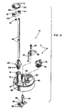
- Figures 1A and 1B are exploded isometric views of a spraying device in accordance with the invention;
- Figure 2 is a cross-sectional assembly view of the spraying device shown in Figures 1A and 1B;
- Figure 3 is a view of a compound four-way control valve in accordance with the invention as seen along the line 3-3 in Figure 2;
- Figure 4 is an isometric view of a telescoping spray tube assembly which may be utilized in a modified form of the spraying device of Figures 1 - 3, showing the spray tube assembly in an extended operating condition;
- Figure 5 is an enlarged cross-sectional view of the telescoping spray tube assembly shown in Figure 4 in a retracted inoperative condition; and
- Figure 6 is an enlarged cross-sectional view taken along the line 6-6 in Figure 5.
- Referring to Figures 1A, 1B and 2, in the illustrated embodiment of the invention a
spraying device 10 is shown in the form of a spray washer comprising a body or housing subassembly 12 (Figures 1B and 2) and a cap subassembly 14 (Figures 1A and 2) through which a primary fluid, such as water, can flow during a spraying operation. Thespraying device 10 further includes a resilient collapsible cylindrical rubber bladder 16 (Figures 1B and 2) which defines a chamber for an additive fluid, such as soap or detergent, and from which the additive fluid can be dispensed during a spraying operation by exerting external pressure on the bladder. - The housing subsassembly 12 (Figures 1B and 2) includes a plastic (e.g., polyethylene) housing 18 of generally cylindrical construction which has an open end 18o and an essentially closed end 18c. A circumferentially extending
support flange 20 is provided around the open end 18o of the housing 15. A projecting connectingportion 22 extends from acylindrical valvemounting portion 23 adjacent the essentially closed end 18c of thehousing 18 and is internally threaded for connecting the housing to a water source, such as a garden hose orpipe 24, illustrated in dashed lines adjacent the bottom of Figure 2. - The connecting
portion 22 and the valve-mounting portion 23 of thehousing 18 include an internal passageway or conduit portion 26 (best shown in Figure 2) which defines an entrance portion of a conduit for the flow of water through the housing. The connectingportion 22 communicates with an elongated tubular passageway orconduit 28 having walls formed integrally with an interior wall of thehousing 18 and extending the length (vertically in Figures 1 and 2) of the housing. Water flow from theentrance passageway 26 into thetubular passageway 28 is controlled by a compound four-way rotatableplastic valve 30. Reverse flow of water in theentrance passageway 26 is precluded by a one-wayplastic check valve 32 of a suitable type. - The collapsible
resilient bladder 16 is positionable in the open end 18o of thehousing 18 into the interior of the housing as shown in Figure 2. Thebladder 16 includes an open end 16o and a circumferentially extendingsupport flange 36 of eccentric construction, as is best shown in Figure 1B. Theflange 36 mates with the circumferentially extendingsupport flange 20 of thehousing 18 and includes a circumferentially extending groove 38 (Figure 2) which receives acorresponding sealing ring 40 of theflange 20. An eccentric portion of theflange 36 includes anaperture 42 formed in the flange so as to be in alignment with thehousing tubular passageway 28. - The essentially closed end wall 18c of the
housing 18 is provided with anorifice 44 which interconnects theentrance passageway 26 of thehousing connecting portion 22 and valve-mountingportion 23 with the interior of the housing so that water can be selectively introduced into the housing to exert external pressure on thebladder 16 within the housing, so as to cause the bladder to collapse and thereby dispense the soap or detergent therein through anorifice 46 formed in a wall of aplastic cap member 48 of the cap subassembly 14. As in the flow of water from theentrance passageway 26 into thetubular passageway 28, flow of water from theentrance passageway 26 through theorifice 44 into the interior of thehousing 18 is controlled by the compoundrotatable control valve 30. - The compound
rotatable control valve 30 is disposed transversely across theentrance passageway 26 of thehousing connecting portion 22 and valve-mountingportion 23 and is rotatably mounted in the valve-mounting portion. Therotatable control valve 30 is maintained in position in the valve-mountingportion 23 by a C-shapedspring clip 50 disposed in acircumferentially extending groove 51 formed in the rotatable valve at the right-hand side thereof as viewed in Figures 1B and 2. Anindicator disc 52, having grippingears 53, is integrally formed on the left hand side of therotatable control valve 30, as viewed in Figures 1B and 2, and includes peripheral indicating grooves 54-O, 54-W, 54-B and 54-S for selectively receiving a locating rib on a lower side of a projecting resilient retainingpost 55 integrally formed on thehousing 18, as is best shown in Figure 1B. Therotatable control valve 30 also carries suitable O-ring seals 56 for precluding flow of water out of theentrance passageway 26 around the opposite ends of the valve. - More specifically, the compound
rotatable control valve 30 includes abody portion 58 having a cylindrical outer surface, but with a part of the body portion cut away to expose an interiorcylindrical surface 60 facing generally toward the direction from which water flows into theentrance passageway 26. Fourvalve ports body portion 58 of thecontrol valve 30 so that one end of each port opens through the cylindrical outer surface of the body portion and an opposite end of each port opens through the interiorcylindrical surface 60 of the body portion. As viewed in Figure 1B, theport 62 extends through thebody portion 58 at an angle to the vertical in a first direction (downward to the left in Figure 1B), theports port 68 extends at an angle to the vertical in an opposite direction (downward to the right in Figure 1B). Theports housing tubular passageway 28 for controlling the flow of water into the tubular passageway, are relatively large in diameter in comparison to theports orifice 44 in the end wall 18c of thehousing 18 for controlling the flow of water through the orifice into the interior of the housing. O-ring seals 69 are disposed in corresponding grooves in the wall 18c of the housing around entrances to thetubular passageway 28 and theorifice 44, respectively. - As is best shown in Figure 2, the essentially closed end wall 18c of the
housing 18 also includes adrain hole 70 surrounded by an O-ring seal 71, and the cylindrical valve-mountingportion 23 of thehousing 18 includes adrain hole 72, for draining water from the interior of the housing and relieving pressure on thebladder 16. For this purpose, therotatable control valve 30 includes adrain port 73 extending diametrically therethrough and alignable with the drain holes 70 and 72 when the valve is in an inoperable "OFF" position. - In operation of the
rotatable control valve 30, rotation of the valve counterclockwise as viewed in Figure 1B, so that the locating rib on the retainingpost 55 is received in the right-hand groove 54-O of theindicator disc 52, moves the valve into its inoperative "OFF" position. In this "OFF" position, neither of theports housing tubular passageway 28, neither of theports housing orifice 44, and thedrain port 73 is aligned with the housing drain holes 70 and 72. When thecontrol valve 30 then is rotated clockwise, as shown in Figure 1B, so that the locating rib of the retainingpost 55 is received in the indicator disc groove 54-W, the valve is moved into a first operative position in which theport 62 is aligned with thetubular passageway 28 for a "WATER RINSE" operation. By then rotating thecontrol valve 30 an additional step clockwise as viewed in Figure 1B, such that the locating rib of the retainingpost 55 is received in the indicator disc groove 54-B, the control valve assumes a second operative position in which theports housing tubular passageway 28 and thehousing orifice 44, respectively, for a "SOAP-AND-WATER" dispensing operation, in which soap in thebladder 16 is dispensed and added to water downstream in thecap member 48 of the cap member subassembly 14, such that mixed soap and water both flow from the sprayingdevice 10. Rotation of thecontrol valve 30 clockwise an additional step in Figure 1B, to position the locating rib of the retainingpost 55 in the disc indicator groove 54-S, then brings the control valve into a third operative condition in which theport 68 is aligned with thehousing orifice 44 for a "SOAP ONLY" operation, in which soap is dispensed from thebladder 16 for discharge from the sprayingdevice 10, while thecentral body portion 58 of thecontrol valve 30 precludes flow of water into thehousing tubular passageway 28 and thus precludes discharge of water from the spraying device. - The soap is dispensed from the
bladder 16 through theorifice 46 in thecap member 48 into an internal passageway orconduit portion 74 which is formed in a projectingpedestal 75 of the cap member and which is aligned with thetubular passageway 28 in thehousing 18. Aremovable plug 76, which includes an O-ring seal 78, is screw threaded into an opening which is formed in apedestal portion 80 of thecap member 48, and through which the bladder can be replenished with soap from a dispenser bottle (not shown) as necessary. Thecap member 48 is of a snap-on type so as to be removably mounted on the open end 18o of thehousing 18 in covering relationship to the open end 16o of thebladder 16, with anannular groove 83 ofbladder support flange 36 receiving a corresponding annular sealing ring on the cap member, as shown in Figure 2. - The cap subassembly 14 includes a rotatably mounted plastic
partial disc member 84 for selectively varying the amount of soap which is dispensed from thebladder 16 through theorifice 46 in thecap member 48. For this purpose, thedisc member 84 has a plurality oforifices 86 of different diameters formed therethrough, and the disc member is rotatably mounted to position a selected one of the orifices in alignment with theorifice 46 in thecap member 48. Flow of soap through theorifice 46 other than by way of one of theorifices 86 in thedisc member 84 is precluded by a suitable O-ring seal 87 (Figure 2). Further, when none of theorifices 86 in thedisc member 84 are in alignment with theorifice 46, the disc member can be utilized to supplement therotatable control valve 30 in precluding flow of soap from thebladder 16. - The
disc member 84 is integrally formed on an inner end of asupport shaft 89 rotatably mounted in a projectingpedestal 90 of thecap member 48. An outer end of thesupport shaft 89 is secured to an operatinglever 92 by ascrew 93. As is shown in Figure 1A, the operatinglever 92 includes a depending indicatingfinger 94 cooperable withsuitable indicia 95 on the top of thecap member 48. A suitable O-ring seal 96 surrounds thesupport shaft 89 within the projectingpedestal 90, as shown in Figure 2. Thepedestal 90 is integrally joined to thecap member pedestal 75 by a reinforcingweb 97. - A fluid conduit portion in the form of an elongated
plastic tube 98, which forms an extension of theinternal passageway 74 in thecap member pedestal 75, has an inner end force-fitted into atube holder 100, and has an outer end force fitted into aplastic support member 102 for a plastic sprayselector disc member 104. Thetube holder 100 includes an inner mounting portion having a slight inward taper (e.g., 1°) which is force-fitted or otherwise suitably mounted into theinternal passageway 74 of thecap member pedestal 75, and which carries a pair of suitable O-ring seals 106. - The spray
selector disc member 104 is removably and rotatably mounted on thesupport member 102 by acentral shaft 108 of the disc member extending through an aperture in the support member, with a suitable C-shapedspring clip 110 disposed in an associated circumferentially extending groove in the central shaft. Thedisc member 104 has a plurality oforifices 112 of different configurations formed therethrough which can be selectively aligned with adischarge opening 114 in thesupport member 102 and the outer end of theelongated tube 98, to provide different spray patterns for a fluid stream emanating from the discharge opening. For example, the disclosed sprayselector disc member 104 includesorifices 112 in the form of a small diameter hole (Figure 1A) for producing a fine spray, a larger diameter hole (Figure 1A) for producing a coarse spray, an elongated slot (Figures 1A and 2) having interior spherically-shaped walls for producing a coarse fan spray, and a similarly shaped shorter slot (Figure 1A) for producing a fine fan spray. Thedisc member 104 also can be removed from thesupport member 102 and replaced with other spray selector disc members (not shown) having spray-defining orifices of other configurations, as desired. An O-ring seal 116 (Figure 2), disposed in a corresponding groove of thesupport member 102, surrounds thedischarge opening 114 in the support member. In addition, a raisedprotruberance 118 is provided on thesupport member 102 for mating with suitably located indentations 120 (one shown in Figure 2) in an opposed surface of the sprayselector disc member 104 for locking the disc member in each of its operative positions. - Figures 4, 5 and 6 disclose a telescoping
spray tube assembly 122 which may be utilized in place of the assembly comprising the one-piece tube 98,tube holder 100, spray selectordisc support member 102 and thespray selector disc 104, in thespraying device 10 shown in Figures 1, 2 and 3, to provide a modifiedspraying device 10′. Thespray tube assembly 122 is constructed such that the assembly automatically extends to an elongated operative position, as shown in Figure 4, in response to pressure caused by the flow of a fluid through the tube assembly, so as to position anozzle 124, which defines a discharge orifice of the tube assembly, closely adjacent an article (not shown) being sprayed. When a spraying operation has been completed, thespray tube assembly 122 may be manually collapsed to a retracted inoperative condition as shown in Figure 5. - The telescoping
spray tube assembly 122 comprises an outerplastic tube 126, an intermediateplastic tube 128, and an innerplastic tube 130 having thedischarge nozzle 124 removably mounted on an outer end thereof. Aninner end portion 132 of theouter tube 126 has an internal diameter such that the inner end portion can be mounted over a projectingpedestal 75′ of acap member 48′ of thespraying device 10′, as shown in Figures 4 and 5. For this purpose, a lower end of theouter tube 126 includes apertured laterally projecting ears 134 (Figure 4) which receive respective upstanding locatingposts 136 formed on thecap member 48′ on opposite sides of thepedestal 75′ and having their upper ends flattened into the form of rivets to retain the telescopingspray tube assembly 122 on thecap member 48′. An O-ring seal 137 for theouter tube 126 is provided on an annular shoulder at an upper end of thepedestal 75′. - The
outer tube 126 also includes a slot 138 (Figure 5) which straddles a reinforcingweb 97′ between thepedestal 75′ and acap member pedestal 90′. Further, anouter end portion 140 of theouter tube 126 is of reduced diameter to limit outward telescoping movement of theintermediate tube 128 therein when thespray tube assembly 122 is in its extended position. - Referring to Figure 5, an inner end of the
intermediate tube 128 includes anannular flange 142 receivable in theouter tube 126 in closely spaced relationship. As in the case of theouter tube 126, anouter end portion 144 of theintermediate tube 128 is of reduced diameter to limit outward telescoping movement of theinner tube 130 therein when thespray tube assembly 122 is in its extended position. Further, thecap member pedestal 75′ includes a vertical inwardly-directedstop rib 145 for precluding theinner tube 130 from dropping into the interior of the pedestal. - An O-ring seal 146 (Figure 5) of circular cross section surrounds the
intermediate tube 128 and is disposed between opposed surfaces of the intermediate tube and theouter tube 126. When thespray tube assembly 122 is in its retracted collapsed condition as shown in Figure 5, the O-ring seal 146 normally is located approximately halfway between theintermediate tube flange 142 and thereduced end portion 140 of theouter tube 126, as shown in that figure. - As in the case of the
intermediate tube 128, an inner end of theinner tube 130 also includes anannular flange 148 which is receivable in theintermediate tube 128 in closely spaced relationship. An O-ring seal 150 of circular cross section, comparable to the O-ring seal 146, surrounds theinner tube 130 approximately halfway between theflange 148 and the reducedouter end portion 144 of theintermediate tube 128, when thespray tube assembly 122 is in its retracted collapsed condition as shown in Figure 5. - As is best shown in Figure 6, an
outer end portion 152 of theinner tube 130 includes a pair of oppositely extending retaining lugs 154 which form parts of a quick-releaseable connection for removably mounting thedischarge nozzle 124 on the inner tube. In this regard, thenozzle 124 is formed with an inner socket in which theouter end portion 152 of theinner tube 130 can be received in seating relationship against an O-ring seal 156. - Referring to Figures 5 and 6, opposite walls of the
discharge nozzle 124 which define the socket therein also include respective ones of a pair of essentially right-angle slots 158 for receiving respective ones of the retaining lugs 154. In use, thenozzle 124 initially is positioned on theouter end portion 152 of theinner tube 130 with the retaining lugs 154 received in axially extending portions of the right-angle slots 158, and then the nozzle is rotated slightly to dispose the lugs in seat portions at inner ends of circumferentially extending portions of the right-angle slots, thereby releasably locking the nozzle on the inner tube. Thus, the nozzle, 124 andother nozzles 160, illustrated at the left-hand left-hand side of Figure 2, of different configurations and having right-angle mounting slots identical to theslots 158, readily can be interchangeably mounted on theinner tube 130 to provide various spray patterns, depending upon the manner in which thespraying device 10′ is being utilized, as desired. For this purpose, referring to Figures 1B and 2, thehousing 18 may include projecting mountinglugs 162 for storing thenozzle 124 and/or the otherinterchangeable nozzles 160 on thespraying device 10′. - In use, when the
control valve 30 shown in Figures 1-3 is operated to its "WATER RINSE" or "SOAP-AND-WATER" positions to cause water or a soap-water mixture, respectively, to flow through the sprayingdevice 10′ into the telescopingspray tube assembly 122, fluid pressure on the intermediate tubeannular flange 142 and the inner tubeannular flange 148 automatically causes theintermediate tube 128 to telescope outwardly in theouter tube 126, and theinner tube 130 to telescope outwardly in the intermediate tube, respectively. Thus, thenozzle 124 on theinner tube 130 can be automatically moved closely adjacent an article (not shown) for a spraying operation in response to actuation of thespraying device 10′. (The same extension of thetube assembly 122 tends to occur, although to a lesser extent, when the control valve is moved into its "SOAP ONLY" operative position.) When the spraying operation is completed and thespraying device 10′ is turned off, thetube assembly 122 can be collapsed manually back to its retracted condition as shown in Figure 5, as noted above. - When the
intermediate tube 128 and theinner tube 130 advance in a telescoping operation, the O-ring seals ring seals outer end portions outer tube 126 and theintermediate tube 128, respectively, with the intermediate tubeannular end flange 142 and the inner tubeannular end flange 148 seating against their respective O-ring seals to limit outward movement of the tubes. Similarly, when thespray tube assembly 122 is collapsed back to its retracted condition as described above, the O-ring seals tube members - In summary, a new and
improved spraying device 10 has been provided in which a primary fluid, such as water, and an additive fluid, such as soap, can be sprayed or dispensed in various spray patterns separately, or as a mixture having selectively, variable concentrations of the additive fluid in the primary fluid. Control for this purpose is provided in part by the compound four-way control valve 30 which is movable from an inoperative "OFF" position into first, second and third "WATER RINSE", "SOAP-AND WATER", and "SOAP ONLY" operative positions. Additional control over the concentration of the additive fluid in the primary fluid is provided by therotatable disc member 84 of the cap subassembly 14 and the plurality oforifices 86 of different diameters in the disc member. In addition, various spray patterns for different uses are provided by the rotatable sprayselector disc member 104 having theorifices 112 of various configurations formed therethrough and selectively positionable in alignment with thedischarge opening 114 in the associatedsupport member 102. The construction of thespraying device 10 also is such that, with minor changes in the construction of thecap member pedestal 75, the telescopingspray tube assembly 122 can be used to provide a modifiedspraying device 10′ if so desired.
Claims (21)
1. A spraying device having controlled additive fluid feed, which comprises:
Conduit means (26) for conveying fluid between an entrance orifice and a discharge orifice of the device;
connecting means (22) adjacent the entrance orifice of the device for connecting the conduit means (26) to a source of a primary fluid;
collapsible chamber means (16) for holding a supply of an additive fluid, the chamber means being in communication with the conduit means (26) and being collapsible in response to external pressure to dispense the additive fluid into the conduit means; and
a control valve (30) disposed in the conduit means (26) for selectively diverting at least a portion of the primary fluid at an upstream portion of the conduit means (26) such that the primary fluid exerts external pressure on the chamber means (16) to cause the chamber means to collapse and dispense the additive fluid into a downstream portion of the conduit means (26);
the control valve (30) being movable from an inoperative position in which no fluid flows through the conduit means (26), into a first operative position in which the control valve (30) permits only the primary fluid to flow through the conduit means (26), and into a second operative position in which the control valve (30) diverts a portion of the primary fluid such that the diverted primary fluid exerts external pressure on the chamber means (16) to cause the additive fluid in the chamber means (16) to be dispensed into the primary fluid flowing through the conduit means,
characterized by
telescoping spray tube means (122) forming part of the conduit means (26) and including the discharge orifice of the spraying device, for spraying fluid from the device.
2. The spraying device as recited in claim 1, in which:
the control valve (30) is a rotatable valve having a first port (62) which is operative when the valve (30) is in the first operative position, and having second (64) and third (66) ports which are operative when the valve (30) is in the second operative position.
the control valve (30) is a rotatable valve having a first port (62) which is operative when the valve (30) is in the first operative position, and having second (64) and third (66) ports which are operative when the valve (30) is in the second operative position.
3. The spraying device as recited in claims 1 or 2, in which:
the control valve (30) is also movable into a third operative position in which the control valve (30) directs the primary fluid such that the primary fluid exerts external pressure on the chamber means (16) to dispense the additive fluid into the downstream portion of the conduit means (26) for discharge from the device through the discharge orifice, while precluding flow of the primary fluid through the conduit means (26) for discharge from the ddevice through the discharge orifice.
the control valve (30) is also movable into a third operative position in which the control valve (30) directs the primary fluid such that the primary fluid exerts external pressure on the chamber means (16) to dispense the additive fluid into the downstream portion of the conduit means (26) for discharge from the device through the discharge orifice, while precluding flow of the primary fluid through the conduit means (26) for discharge from the ddevice through the discharge orifice.
4. The spraying device as recited in claim 3, which further comprises:
a fourth port (68) which is operative when the valve (30) is in the third operative position.
a fourth port (68) which is operative when the valve (30) is in the third operative position.
5. The spraying device as recited in anyone of claims 1 - 4, which further comprises:
control means (84) adjacent the collapsible chamber means (16) for varying the amount of additive fluid dispensed from the chamber means (16) into the conduit means (26).
control means (84) adjacent the collapsible chamber means (16) for varying the amount of additive fluid dispensed from the chamber means (16) into the conduit means (26).
6. The spraying device as recited in claim 5, in which:
the control means is a rotatably mounted disc member (84) having a plurality of orifices (86) of various sizes formed therethrough.
the control means is a rotatably mounted disc member (84) having a plurality of orifices (86) of various sizes formed therethrough.
7. The spraying device as recited in anyone of claims 1 - 5, which further comprises:
spray selector means (104) movably mounted adjacent the discharge orifice (114) of the device and having a plurality of orifices (112) of different configurations formed therethrough, the spray selector means (104) being movable to position respective ones of the orifices (112) therein in alignment with the discharge orifice (114) of the device to vary the configuration of a fluid stream emanating from the discharge orifice (114).
spray selector means (104) movably mounted adjacent the discharge orifice (114) of the device and having a plurality of orifices (112) of different configurations formed therethrough, the spray selector means (104) being movable to position respective ones of the orifices (112) therein in alignment with the discharge orifice (114) of the device to vary the configuration of a fluid stream emanating from the discharge orifice (114).
8. The spraying device as recited in claim 7, in which:
the spray selector means is a rotatably mounted disc member (104).
the spray selector means is a rotatably mounted disc member (104).
9. The spraying device as recited in anyone of claims 1 - 8, which further comprises:
a housing (12) open at a first end, the housing (12) having the device entrance orifice formed in the housing adjacent a second opposite end and also having a portion of the device conduit means (22) formed therein, the portion of the device conduit means formed in the housing including an elongated tubular passageway (28) integrally formed with a wall of the housing (18) and extending from the second end to the first open end of the housing,
connecting means (22) on the housing (18) adjacent the entrance orifice in the housing for connecting the portion of the conduit means (22) in the housing to a conduit for introducing a primary fluid into the conduit means;
a resilient bladder (16) having an open end and positioned in the open end of the housing (18) for holding a supply of an additive fluid, the housing (18) having an orifice (44) therein adjacent the second end of the housing and through which the primary fluid can flow to exert external pressure on the bladder (16);
a cap member (48) mounted on the open end of the housing (18) in covering relationship to the open end of the bladder (16), the cap member (48) also having a portion of the conduit means formed therein in alignment with the portion of the conduit means in the housing, including the elongated tubular passageway, and having an orifice (46) therein through which the additive fluid can flow from the open end of the bladder (16) into the device conduit means (26),
first control means (30) mounted in the housing (18) adjacent the entrance orifice in the housing for selectively diverting at least a portion of the primary fluid into the orifice (44) in the housing such that the primary fluid exerts external pressure on the bladder (16) to cause the bladder to collapse and dispense the additive fluid from the open end of the bladder through the orifice (46) in the cap member (48) and into the device conduit means (26); and
second control means (84) mounted on the cap member (48) for varying the amount of the additive fluid dispensed from the open end of the bladder (16) into the device conduit means (26).
10. The spraying device as recited in claim 9, in which:
the first control means (30) is selectively movable into an inoperative "OFF" position, a first operative position in which the first control means (30) permits only the primary fluid to flow through the device conduit means (26), a second operative position in which the first control means (30) diverts a portion of the primary fluid through the orifice (44) in the housing (18) to exert external pressure on the bladder (16), while also permitting the primary fluid to flow through the device conduit means (26), and a third operative position in which the first control means (30) directs the primary fluid through the orifice (44) in the housing (18) to exert external pressure on the bladder (16) and thereby to dispense the additive fluid into the device conduit means (26) for discharge through the discharge orifice of the device, while precluding the primary fluid from flowing through the device conduit means (26) for discharge through the discharge orifice.
the first control means (30) is selectively movable into an inoperative "OFF" position, a first operative position in which the first control means (30) permits only the primary fluid to flow through the device conduit means (26), a second operative position in which the first control means (30) diverts a portion of the primary fluid through the orifice (44) in the housing (18) to exert external pressure on the bladder (16), while also permitting the primary fluid to flow through the device conduit means (26), and a third operative position in which the first control means (30) directs the primary fluid through the orifice (44) in the housing (18) to exert external pressure on the bladder (16) and thereby to dispense the additive fluid into the device conduit means (26) for discharge through the discharge orifice of the device, while precluding the primary fluid from flowing through the device conduit means (26) for discharge through the discharge orifice.
11. The spraying device as recited in claim 10, in which:
the first control means is a rotatable valve (30) having a first port (62) which is operative when the valve (30) is in the first operative position, second (64) and third (66) ports which are operative when the valve (30) is in the second operative position, a fourth port (68) which is operative when the valve (30) is in the third operative position, and a fifth port (73) for draining the primary fluid from the housing (18) and releasing pressure in the bladder (16) when the valve (30) is in the inoperative "OFF" position.
the first control means is a rotatable valve (30) having a first port (62) which is operative when the valve (30) is in the first operative position, second (64) and third (66) ports which are operative when the valve (30) is in the second operative position, a fourth port (68) which is operative when the valve (30) is in the third operative position, and a fifth port (73) for draining the primary fluid from the housing (18) and releasing pressure in the bladder (16) when the valve (30) is in the inoperative "OFF" position.
12. The spraying device as recited in anyone of claims 1 - 11, in which:
the telescoping spray tube means (122) includes means (148) for automatically extending a portion of the spray tube means outwardly in response to pressure produced by fluid flowing through the spray tube means.
the telescoping spray tube means (122) includes means (148) for automatically extending a portion of the spray tube means outwardly in response to pressure produced by fluid flowing through the spray tube means.
13. The spraying device as recited in claim 12, in which:
the telescoping spray tube means (122) includes an outer tube (126) and at least one additional inner tube (128, 130) reciprocably disposed in the outer tube (126) and extendable outwardly relative to the outer tube;
the automatic extending means includes an annular flange (148) on an inner end of the inner tube responsive to fluid pressure to cause the inner tube to move in the outer tube outwardly relative to the outer tube; and
the outer tube (126) includes movement limiting means (140) at an outer end thereof cooperable with the annular flange (148) to limit outward movement of the flange and the inner tube in the outer tube.
14. The spraying device as recited in claim 13, which further comprises:
an annular seal (146, 150) surrounding the inner tube (128, 130) between the inner tube (128, 130) and the outer tube (130, 126) for rolling movement with the inner tube as the inner tube reciprocates in the outer tube, with the seal being rollable into an intermediate position between the annular flange (148) on the inner tube and the annular flange movement limiting means (140) on the outer end of the outer tube when the inner tube is retracted, and against the annular flange movement limiting means (140) on the outer tube when the inner tube is extended.
an annular seal (146, 150) surrounding the inner tube (128, 130) between the inner tube (128, 130) and the outer tube (130, 126) for rolling movement with the inner tube as the inner tube reciprocates in the outer tube, with the seal being rollable into an intermediate position between the annular flange (148) on the inner tube and the annular flange movement limiting means (140) on the outer end of the outer tube when the inner tube is retracted, and against the annular flange movement limiting means (140) on the outer tube when the inner tube is extended.
15. The spraying device as recited in claim 14, in which:
the intermediate position of the annular seal (146, 150) when the inner tube (128, 130) is retracted, is essentially halfway between the annular flange (148) on the inner tube and the annular flange movement limiting means (140) on the outer tube.
the intermediate position of the annular seal (146, 150) when the inner tube (128, 130) is retracted, is essentially halfway between the annular flange (148) on the inner tube and the annular flange movement limiting means (140) on the outer tube.
16. The spraying device as recited in anyone of claims 1 - 15, in which:
the telescoping spray tube means (122) having an inner end connected to the housing assembly (12) in fluid communication with the conduit means (26) in the housing assembly, with the remainder of the telescoping spray tube means (122) projecting outward from the housing assembly (12).
the telescoping spray tube means (122) having an inner end connected to the housing assembly (12) in fluid communication with the conduit means (26) in the housing assembly, with the remainder of the telescoping spray tube means (122) projecting outward from the housing assembly (12).
17. The spraying device as recited in anyone of claims 1 - 16, in which:
the telescoping spray tube means (122) includes an outer tube (126) which defines the inner end of the telescoping spray tube means connected to the housing assembly (12) and which projects outward from the housing assembly, and at least one additional inner tube (128, 130) reciprocably disposed in the outer tube for movement between extended and retracted positions and extendable outwardly relative to the outer tube (126).
the telescoping spray tube means (122) includes an outer tube (126) which defines the inner end of the telescoping spray tube means connected to the housing assembly (12) and which projects outward from the housing assembly, and at least one additional inner tube (128, 130) reciprocably disposed in the outer tube for movement between extended and retracted positions and extendable outwardly relative to the outer tube (126).
18. The spraying device as recited in anyone of claims 2 - 17, in which:
the first (62) and second (64) ports in the rotatable valve (30) are circumferentially aligned and are selectively movable into alignment with the conduit means (26), and the second (64) and third (66) ports in the rotatable valve (30) are spaced axially along the axis of rotation of the valve, with the third port (66) being movable into alignment with a first orifice (44) in a housing assembly (12) for holding the collapsible chamber means (16).
the first (62) and second (64) ports in the rotatable valve (30) are circumferentially aligned and are selectively movable into alignment with the conduit means (26), and the second (64) and third (66) ports in the rotatable valve (30) are spaced axially along the axis of rotation of the valve, with the third port (66) being movable into alignment with a first orifice (44) in a housing assembly (12) for holding the collapsible chamber means (16).
19. The spraying device as recited in claim 18, in which:
the rotatable control valve (30) has a fourth port (68) in circumferentially extending alignment with the third port (66) and movable into alignment with the first orifice (44) in the housing assembly (12), to direct at least a portion of the primary fluid through the first orifice (44) and thereby exert external pressure on the chamber means (16), to dispense additive fluid only through a second orifice of the housing assembly.
the rotatable control valve (30) has a fourth port (68) in circumferentially extending alignment with the third port (66) and movable into alignment with the first orifice (44) in the housing assembly (12), to direct at least a portion of the primary fluid through the first orifice (44) and thereby exert external pressure on the chamber means (16), to dispense additive fluid only through a second orifice of the housing assembly.
20. The spraying device as recited in claim 19, in which:
the housing (12) has a drain opening (70) adjacent the rotatable control valve (30) and the valve has a fifth port (73) movable into alignment with the drain opening to drain the housing.
the housing (12) has a drain opening (70) adjacent the rotatable control valve (30) and the valve has a fifth port (73) movable into alignment with the drain opening to drain the housing.
21. The spraying device as recited in claim 20, in which:
the rotatable valve (30), the first orifice (44) in the housing assembly (12) and the housing drain opening (70) all are located at the same end of the housing (12).
the rotatable valve (30), the first orifice (44) in the housing assembly (12) and the housing drain opening (70) all are located at the same end of the housing (12).
Priority Applications (1)
| Application Number | Priority Date | Filing Date | Title |
|---|---|---|---|
| EP19900107259 EP0386800A1 (en) | 1985-03-20 | 1986-03-20 | Spraying device having controlled additive fluid feed and a telescoping spray tube assembly |
Applications Claiming Priority (3)
| Application Number | Priority Date | Filing Date | Title |
|---|---|---|---|
| US713824 | 1985-03-20 | ||
| US06/713,824 US4682734A (en) | 1985-03-20 | 1985-03-20 | Spraying device having controlled additive fluid feed and a telescoping spray tube assembly |
| EP19900107259 EP0386800A1 (en) | 1985-03-20 | 1986-03-20 | Spraying device having controlled additive fluid feed and a telescoping spray tube assembly |
Related Parent Applications (1)
| Application Number | Title | Priority Date | Filing Date |
|---|---|---|---|
| EP86902597.3 Division | 1986-03-20 |
Publications (1)
| Publication Number | Publication Date |
|---|---|
| EP0386800A1 true EP0386800A1 (en) | 1990-09-12 |
Family
ID=26125115
Family Applications (1)
| Application Number | Title | Priority Date | Filing Date |
|---|---|---|---|
| EP19900107259 Withdrawn EP0386800A1 (en) | 1985-03-20 | 1986-03-20 | Spraying device having controlled additive fluid feed and a telescoping spray tube assembly |
Country Status (1)
| Country | Link |
|---|---|
| EP (1) | EP0386800A1 (en) |
Cited By (20)
| Publication number | Priority date | Publication date | Assignee | Title |
|---|---|---|---|---|
| WO1998005853A1 (en) * | 1996-08-07 | 1998-02-12 | Cuno, Inc. | Additive dispensing apparatus |
| DE10213715A1 (en) * | 2001-11-14 | 2003-05-22 | Martin Ruda | Tank for a spray gun for coating substances comprises a tank part and a fixed tank liner |
| WO2009115200A1 (en) * | 2008-03-17 | 2009-09-24 | Boehringer Ingelheim International Gmbh | Reservoir and nebulizer |
| US9545487B2 (en) | 2012-04-13 | 2017-01-17 | Boehringer Ingelheim International Gmbh | Dispenser with encoding means |
| US9682202B2 (en) | 2009-05-18 | 2017-06-20 | Boehringer Ingelheim International Gmbh | Adapter, inhalation device, and atomizer |
| US9724482B2 (en) | 2009-11-25 | 2017-08-08 | Boehringer Ingelheim International Gmbh | Nebulizer |
| US9744313B2 (en) | 2013-08-09 | 2017-08-29 | Boehringer Ingelheim International Gmbh | Nebulizer |
| US9757750B2 (en) | 2011-04-01 | 2017-09-12 | Boehringer Ingelheim International Gmbh | Medicinal device with container |
| US9827384B2 (en) | 2011-05-23 | 2017-11-28 | Boehringer Ingelheim International Gmbh | Nebulizer |
| US9943654B2 (en) | 2010-06-24 | 2018-04-17 | Boehringer Ingelheim International Gmbh | Nebulizer |
| US10004857B2 (en) | 2013-08-09 | 2018-06-26 | Boehringer Ingelheim International Gmbh | Nebulizer |
| US10011906B2 (en) | 2009-03-31 | 2018-07-03 | Beohringer Ingelheim International Gmbh | Method for coating a surface of a component |
| US10016568B2 (en) | 2009-11-25 | 2018-07-10 | Boehringer Ingelheim International Gmbh | Nebulizer |
| US10099022B2 (en) | 2014-05-07 | 2018-10-16 | Boehringer Ingelheim International Gmbh | Nebulizer |
| US10124125B2 (en) | 2009-11-25 | 2018-11-13 | Boehringer Ingelheim International Gmbh | Nebulizer |
| US10124129B2 (en) | 2008-01-02 | 2018-11-13 | Boehringer Ingelheim International Gmbh | Dispensing device, storage device and method for dispensing a formulation |
| US10195374B2 (en) | 2014-05-07 | 2019-02-05 | Boehringer Ingelheim International Gmbh | Container, nebulizer and use |
| US10722666B2 (en) | 2014-05-07 | 2020-07-28 | Boehringer Ingelheim International Gmbh | Nebulizer with axially movable and lockable container and indicator |
| DE10394380B4 (en) * | 2002-12-10 | 2021-05-06 | Sata Gmbh & Co. Kg | Single wall spray gun cup |
| CN112762211A (en) * | 2021-01-14 | 2021-05-07 | 赵宣普 | Prefabricated disinfectant faucet |
Citations (5)
| Publication number | Priority date | Publication date | Assignee | Title |
|---|---|---|---|---|
| FR500920A (en) * | 1917-06-21 | 1920-03-27 | Pierre Billard | Device for painting large surfaces |
| US1769944A (en) * | 1927-12-27 | 1930-07-08 | George B Crisp | Cleaning apparatus |
| US3567125A (en) * | 1968-06-28 | 1971-03-02 | Henderson D Houghton | Spraying and irrigation equipment |
| US3938218A (en) * | 1973-11-07 | 1976-02-17 | Deamicis Ferdinando | Extensible cleaning tool |
| FR2549388A1 (en) * | 1983-07-21 | 1985-01-25 | Waldner Roland | PORTABLE DEVICE FOR INJECTING AND MIXING A LIQUID OR PASTY PRODUCT INTO A WATER CIRCUIT |
-
1986
- 1986-03-20 EP EP19900107259 patent/EP0386800A1/en not_active Withdrawn
Patent Citations (5)
| Publication number | Priority date | Publication date | Assignee | Title |
|---|---|---|---|---|
| FR500920A (en) * | 1917-06-21 | 1920-03-27 | Pierre Billard | Device for painting large surfaces |
| US1769944A (en) * | 1927-12-27 | 1930-07-08 | George B Crisp | Cleaning apparatus |
| US3567125A (en) * | 1968-06-28 | 1971-03-02 | Henderson D Houghton | Spraying and irrigation equipment |
| US3938218A (en) * | 1973-11-07 | 1976-02-17 | Deamicis Ferdinando | Extensible cleaning tool |
| FR2549388A1 (en) * | 1983-07-21 | 1985-01-25 | Waldner Roland | PORTABLE DEVICE FOR INJECTING AND MIXING A LIQUID OR PASTY PRODUCT INTO A WATER CIRCUIT |
Cited By (28)
| Publication number | Priority date | Publication date | Assignee | Title |
|---|---|---|---|---|
| WO1998005853A1 (en) * | 1996-08-07 | 1998-02-12 | Cuno, Inc. | Additive dispensing apparatus |
| US5919360A (en) * | 1996-08-07 | 1999-07-06 | Cuno, Inc. | Additive dispensing apparatus |
| AU720940B2 (en) * | 1996-08-07 | 2000-06-15 | 3M Innovative Properties Company | Additive dispensing apparatus |
| DE10213715A1 (en) * | 2001-11-14 | 2003-05-22 | Martin Ruda | Tank for a spray gun for coating substances comprises a tank part and a fixed tank liner |
| DE10394380B4 (en) * | 2002-12-10 | 2021-05-06 | Sata Gmbh & Co. Kg | Single wall spray gun cup |
| US10124129B2 (en) | 2008-01-02 | 2018-11-13 | Boehringer Ingelheim International Gmbh | Dispensing device, storage device and method for dispensing a formulation |
| WO2009115200A1 (en) * | 2008-03-17 | 2009-09-24 | Boehringer Ingelheim International Gmbh | Reservoir and nebulizer |
| US8650840B2 (en) | 2008-03-17 | 2014-02-18 | Boehringer Ingelheim International Gmbh | Reservoir for nebulizer with a deformable fluid chamber |
| US9623200B2 (en) | 2008-03-17 | 2017-04-18 | Boehringer Ingelheim International Gmbh | Reservoir for nebulizer with a deformable fluid chamber |
| US10011906B2 (en) | 2009-03-31 | 2018-07-03 | Beohringer Ingelheim International Gmbh | Method for coating a surface of a component |
| US9682202B2 (en) | 2009-05-18 | 2017-06-20 | Boehringer Ingelheim International Gmbh | Adapter, inhalation device, and atomizer |
| US9724482B2 (en) | 2009-11-25 | 2017-08-08 | Boehringer Ingelheim International Gmbh | Nebulizer |
| US10124125B2 (en) | 2009-11-25 | 2018-11-13 | Boehringer Ingelheim International Gmbh | Nebulizer |
| US10016568B2 (en) | 2009-11-25 | 2018-07-10 | Boehringer Ingelheim International Gmbh | Nebulizer |
| US9943654B2 (en) | 2010-06-24 | 2018-04-17 | Boehringer Ingelheim International Gmbh | Nebulizer |
| US9757750B2 (en) | 2011-04-01 | 2017-09-12 | Boehringer Ingelheim International Gmbh | Medicinal device with container |
| US9827384B2 (en) | 2011-05-23 | 2017-11-28 | Boehringer Ingelheim International Gmbh | Nebulizer |
| US10220163B2 (en) | 2012-04-13 | 2019-03-05 | Boehringer Ingelheim International Gmbh | Nebuliser with coding means |
| US9545487B2 (en) | 2012-04-13 | 2017-01-17 | Boehringer Ingelheim International Gmbh | Dispenser with encoding means |
| US10004857B2 (en) | 2013-08-09 | 2018-06-26 | Boehringer Ingelheim International Gmbh | Nebulizer |
| US9744313B2 (en) | 2013-08-09 | 2017-08-29 | Boehringer Ingelheim International Gmbh | Nebulizer |
| US10894134B2 (en) | 2013-08-09 | 2021-01-19 | Boehringer Ingelheim International Gmbh | Nebulizer |
| US11642476B2 (en) | 2013-08-09 | 2023-05-09 | Boehringer Ingelheim International Gmbh | Nebulizer |
| US10716905B2 (en) | 2014-02-23 | 2020-07-21 | Boehringer Lngelheim International Gmbh | Container, nebulizer and use |
| US10099022B2 (en) | 2014-05-07 | 2018-10-16 | Boehringer Ingelheim International Gmbh | Nebulizer |
| US10195374B2 (en) | 2014-05-07 | 2019-02-05 | Boehringer Ingelheim International Gmbh | Container, nebulizer and use |
| US10722666B2 (en) | 2014-05-07 | 2020-07-28 | Boehringer Ingelheim International Gmbh | Nebulizer with axially movable and lockable container and indicator |
| CN112762211A (en) * | 2021-01-14 | 2021-05-07 | 赵宣普 | Prefabricated disinfectant faucet |
Similar Documents
| Publication | Publication Date | Title |
|---|---|---|
| US4682734A (en) | Spraying device having controlled additive fluid feed and a telescoping spray tube assembly | |
| EP0386800A1 (en) | Spraying device having controlled additive fluid feed and a telescoping spray tube assembly | |
| US4886212A (en) | Spraying device having controlled additive fluid feed and a telescoping spray tube assembly | |
| US10328398B2 (en) | Multiple function dispenser | |
| JP3542609B2 (en) | Improved spray device | |
| US6345773B1 (en) | Aspiration-type sprayer | |
| US3207443A (en) | Dual spray head having vent control means | |
| US9427755B2 (en) | Spraying device with interchangeable cartridge | |
| KR910008933B1 (en) | Dual function cap | |
| EP1184084A2 (en) | Hose-end aspiration-type sprayer | |
| CA3118300C (en) | Sprayer | |
| WO1989000889A1 (en) | Spraying device having an additive fluid dispenser at an exit end | |
| US5964415A (en) | Portable water--mixture dispenser | |
| AU709157B2 (en) | Liquid dispenser with flow control | |
| US3933179A (en) | Water and concentrate supply valves for proportioning mixer-dispenser | |
| AU2023202789A1 (en) | Sprayer Able to Adjust Flow of Mixed Solution and Clear Water | |
| US5474210A (en) | Fluid dispensing device | |
| NO864625L (en) | CONTROLLED DUAL FLUID SPRAY EQUIPMENT WITH TELESCOPING SPRAY ERA. | |
| MXPA99009552A (en) | An improved spraying device | |
| WO1999039835A1 (en) | Aspiration-type sprayer |
Legal Events
| Date | Code | Title | Description |
|---|---|---|---|
| PUAI | Public reference made under article 153(3) epc to a published international application that has entered the european phase |
Free format text: ORIGINAL CODE: 0009012 |
|
| AC | Divisional application: reference to earlier application |
Ref document number: 216895 Country of ref document: EP |
|
| AK | Designated contracting states |
Kind code of ref document: A1 Designated state(s): AT BE CH DE FR GB IT LI LU NL SE |
|
| RIN1 | Information on inventor provided before grant (corrected) |
Inventor name: REINSTEIN, FRED M. Inventor name: PROCTOR, RUDY R. |
|
| STAA | Information on the status of an ep patent application or granted ep patent |
Free format text: STATUS: THE APPLICATION IS DEEMED TO BE WITHDRAWN |
|
| 18D | Application deemed to be withdrawn |
Effective date: 19910313 |