EP0376873B1 - Appareil pour numériser le contour d'une surface dentaire, en particulier pour préparer une couronne dentaire. - Google Patents
Appareil pour numériser le contour d'une surface dentaire, en particulier pour préparer une couronne dentaire. Download PDFInfo
- Publication number
- EP0376873B1 EP0376873B1 EP89630211A EP89630211A EP0376873B1 EP 0376873 B1 EP0376873 B1 EP 0376873B1 EP 89630211 A EP89630211 A EP 89630211A EP 89630211 A EP89630211 A EP 89630211A EP 0376873 B1 EP0376873 B1 EP 0376873B1
- Authority
- EP
- European Patent Office
- Prior art keywords
- probe
- deflection
- handle
- arm
- along
- Prior art date
- Legal status (The legal status is an assumption and is not a legal conclusion. Google has not performed a legal analysis and makes no representation as to the accuracy of the status listed.)
- Expired - Lifetime
Links
Images


Classifications
-
- A—HUMAN NECESSITIES
- A61—MEDICAL OR VETERINARY SCIENCE; HYGIENE
- A61C—DENTISTRY; APPARATUS OR METHODS FOR ORAL OR DENTAL HYGIENE
- A61C19/00—Dental auxiliary appliances
- A61C19/04—Measuring instruments specially adapted for dentistry
-
- G—PHYSICS
- G05—CONTROLLING; REGULATING
- G05B—CONTROL OR REGULATING SYSTEMS IN GENERAL; FUNCTIONAL ELEMENTS OF SUCH SYSTEMS; MONITORING OR TESTING ARRANGEMENTS FOR SUCH SYSTEMS OR ELEMENTS
- G05B19/00—Programme-control systems
- G05B19/02—Programme-control systems electric
- G05B19/42—Recording and playback systems, i.e. in which the programme is recorded from a cycle of operations, e.g. the cycle of operations being manually controlled, after which this record is played back on the same machine
- G05B19/4202—Recording and playback systems, i.e. in which the programme is recorded from a cycle of operations, e.g. the cycle of operations being manually controlled, after which this record is played back on the same machine preparation of the programme medium using a drawing, a model
- G05B19/4207—Recording and playback systems, i.e. in which the programme is recorded from a cycle of operations, e.g. the cycle of operations being manually controlled, after which this record is played back on the same machine preparation of the programme medium using a drawing, a model in which a model is traced or scanned and corresponding data recorded
-
- A—HUMAN NECESSITIES
- A61—MEDICAL OR VETERINARY SCIENCE; HYGIENE
- A61C—DENTISTRY; APPARATUS OR METHODS FOR ORAL OR DENTAL HYGIENE
- A61C13/00—Dental prostheses; Making same
- A61C13/0003—Making bridge-work, inlays, implants or the like
- A61C13/0004—Computer-assisted sizing or machining of dental prostheses
-
- A—HUMAN NECESSITIES
- A61—MEDICAL OR VETERINARY SCIENCE; HYGIENE
- A61C—DENTISTRY; APPARATUS OR METHODS FOR ORAL OR DENTAL HYGIENE
- A61C9/00—Impression cups, i.e. impression trays; Impression methods
- A61C9/004—Means or methods for taking digitized impressions
- A61C9/0046—Data acquisition means or methods
- A61C9/008—Mechanical means or methods, e.g. a contact probe moving over the teeth
-
- G—PHYSICS
- G05—CONTROLLING; REGULATING
- G05B—CONTROL OR REGULATING SYSTEMS IN GENERAL; FUNCTIONAL ELEMENTS OF SUCH SYSTEMS; MONITORING OR TESTING ARRANGEMENTS FOR SUCH SYSTEMS OR ELEMENTS
- G05B2219/00—Program-control systems
- G05B2219/30—Nc systems
- G05B2219/37—Measurements
- G05B2219/37039—Digitize position with flexible feeler, correction of position as function of flexion
-
- G—PHYSICS
- G05—CONTROLLING; REGULATING
- G05B—CONTROL OR REGULATING SYSTEMS IN GENERAL; FUNCTIONAL ELEMENTS OF SUCH SYSTEMS; MONITORING OR TESTING ARRANGEMENTS FOR SUCH SYSTEMS OR ELEMENTS
- G05B2219/00—Program-control systems
- G05B2219/30—Nc systems
- G05B2219/37—Measurements
- G05B2219/37273—Wheatstone bridge
-
- G—PHYSICS
- G05—CONTROLLING; REGULATING
- G05B—CONTROL OR REGULATING SYSTEMS IN GENERAL; FUNCTIONAL ELEMENTS OF SUCH SYSTEMS; MONITORING OR TESTING ARRANGEMENTS FOR SUCH SYSTEMS OR ELEMENTS
- G05B2219/00—Program-control systems
- G05B2219/30—Nc systems
- G05B2219/37—Measurements
- G05B2219/37274—Strain gauge
-
- G—PHYSICS
- G05—CONTROLLING; REGULATING
- G05B—CONTROL OR REGULATING SYSTEMS IN GENERAL; FUNCTIONAL ELEMENTS OF SUCH SYSTEMS; MONITORING OR TESTING ARRANGEMENTS FOR SUCH SYSTEMS OR ELEMENTS
- G05B2219/00—Program-control systems
- G05B2219/30—Nc systems
- G05B2219/37—Measurements
- G05B2219/37357—Force, pressure, weight or deflection
-
- G—PHYSICS
- G05—CONTROLLING; REGULATING
- G05B—CONTROL OR REGULATING SYSTEMS IN GENERAL; FUNCTIONAL ELEMENTS OF SUCH SYSTEMS; MONITORING OR TESTING ARRANGEMENTS FOR SUCH SYSTEMS OR ELEMENTS
- G05B2219/00—Program-control systems
- G05B2219/30—Nc systems
- G05B2219/41—Servomotor, servo controller till figures
- G05B2219/41206—Lookup table, memory with certain relationships
-
- G—PHYSICS
- G05—CONTROLLING; REGULATING
- G05B—CONTROL OR REGULATING SYSTEMS IN GENERAL; FUNCTIONAL ELEMENTS OF SUCH SYSTEMS; MONITORING OR TESTING ARRANGEMENTS FOR SUCH SYSTEMS OR ELEMENTS
- G05B2219/00—Program-control systems
- G05B2219/30—Nc systems
- G05B2219/45—Nc applications
- G05B2219/45167—Dentist, dental manufacture
-
- G—PHYSICS
- G16—INFORMATION AND COMMUNICATION TECHNOLOGY [ICT] SPECIALLY ADAPTED FOR SPECIFIC APPLICATION FIELDS
- G16H—HEALTHCARE INFORMATICS, i.e. INFORMATION AND COMMUNICATION TECHNOLOGY [ICT] SPECIALLY ADAPTED FOR THE HANDLING OR PROCESSING OF MEDICAL OR HEALTHCARE DATA
- G16H20/00—ICT specially adapted for therapies or health-improving plans, e.g. for handling prescriptions, for steering therapy or for monitoring patient compliance
- G16H20/40—ICT specially adapted for therapies or health-improving plans, e.g. for handling prescriptions, for steering therapy or for monitoring patient compliance relating to mechanical, radiation or invasive therapies, e.g. surgery, laser therapy, dialysis or acupuncture
Definitions
- the present invention relates to apparatus for digitizing the contour of a three-dimensional dental surface.
- the invention is particularly applicable for digitizing a dental surface, e.g., a ground tooth for preparing a dental crown, and is therefore described below with respect to this application.
- a tooth When a tooth is in an advanced state of decay, it may become necessary to apply a crown. This involves grinding the tooth and then fixing the crown to it. If one or more teeth are missing or are to be removed, it may be necessary to insert a bridge, which includes a crown applied to each of the two teeth to be bridged and integrally formed with one or more artificial teeth to fill the space of the missing tooth or teeth.
- the metal infrastructure for preparing a crown or bridge is conventionally produced by making a cast model of the respective part of the oral cavity, and then using the cast model for building the crown or bridge.
- Such a procedure is very time-consuming and requires a large number of visits by the patient to the dentist.
- this procedure is greatly dependent on the skill and experience of both the dentist and the laboratory technician in making the cast model and the crown or bridge based on it, as well as on the precision of the equipment used.
- US-A-4,478,580 discloses apparatus for treating teeth in which a rotary cutter head is provided with stress sensors so that both the shape of the tooth being ground, as well as the resistance to grinding, are sensed during the grinding operation.
- DE-A-3 031 085 discloses a procedure for controlling a duplicating milling machine by probing a master mounted on a stage with a deflectable feeler, in which the deflections of the feeler are subtracted from the position of the feeler slide so as to increase the precision of the position of the feeler tip with respect to the contour of the master.
- FR-A-2 468 441 discloses a system for reproducing a mold of a model in which a probe is provided with elastic arms, produces a signal to stop the displacement of the probe support and to store its position in memory.
- US-A- 4,182,312 discloses a contact-type dental probe in which an aluminum tray is fixed in the patient's mouth such that when the dentist applies the probe to the patient's tooth or gum tissues, an electrical circuit is completed, via the saliva in the patient's mouth, to the tray to enable the transducer to output the positional signals of the probe.
- the contact of the probe with the surface being digitized is based on completing an electrical circuit to the tray via the subject's saliva, the results would be distorted by the thickness of the saliva film, which is significant when compared to the precision required for dental probes of this type.
- An object of the present invention is to provide improved apparatus for digitizing the contour of a three-dimensional surface, particularly a dental surface to enable dental crowns and bridges to be produced in a more efficient manner than by the present conventional techniques, and in a more precise manner than in the previously-proposed automated techniques.
- the apparatus of the invention for digitizing the contour of a dental surface of a subject is characterized by the features set forth in the characterizing part of Claim 1.
- the probe of the apparatus includes an arm deflectable along first and second ones of the three independent axes during the movement of the probe along the three-dimensional surface by the handle, and first and second deflection sensor means for sensing the deflection of the arm along the said first and second axes, respectively, and for outputting deflection values corresponding thereto.
- Each of the deflection sensor means comprises a strain sensor fixed on a side of said deflector arm in alignment with its respective axis.
- the digital processor includes means for processing the positional values only when one of the deflection sensors senses a deflection in its respective arm above a predetermined threshold value, and means for modifying the positional values by the deflection values to output digital surface-location values representing the loction of the sample points on the three-dimensional surface during the movement of the probe therealong by the handle.
- the apparatus of the present invention is particularly useful in a dental probe apparatus as described in US-A-4,182,312 but avoids the above-described drawbacks of that apparatus.
- the deflection sensors serve the double function of: (1) determining when contact is made by the probe with the dental surface being contoured, and (2) correcting the measurements by the deflections of the probe.
- the apparatus thus permits dental surfaces to be digitized in an automatic and highly-precise manner.
- a deflection sensor for the third axis may be provided but is not essential for the above purposes.
- the above-described apparatus is particularly useful for digitizing a dental surface of a subject, in which case the described mounting means includes a biting member to be clamped between the upper and lower teeth of the subject.
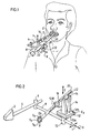
- Figs. 1 and 2 illustrate a probe assembly constructed in accordance with the present invention for use in digitizing the contour of the surface of a tooth to receive a dental crown. After the dentist has ground the tooth as required, this probe assembly would be used with the data processor system illustrated in Fig. 8 to digitize the contour of the ground surface of the tooth in order to produce digital data for use in automatically preparing the crown according to that contour.
- the probe assembly illustrated in Figs. 1 and 2 comprises a wedge-shaped mounting member 2 to be clamped between the upper and lower teeth of the subject.
- Mounting member 2 is secured to one end of an arm 4 connected at its opposite end by an articulated joint 6 to one end of a second arm 8.
- the opposite end of arm 8 carries an articulated joint 10 to which is mounted one section 12a of a slide 12, having a second, relatively-movable section 12b to which is mounted a base member 14.
- Base member 14 mounts one section 16a of a further slide 16 having a second, relatively-movable section 16b which is movable perpendicularly to the direction of movement of section 12b of slide 12.
- Slide section 12b in turn mounts one section 18a of a third slide 18 having a second, relatively-movable section 18b movable perpendicularly to the directions of movements of both slide sections 12b and 16b.
- Slide section 18b in turn mounts a handle 20 knurled at one end 22 to facilitate grasping by the dentist.
- the opposite end of handle 20 mounts a probe head 24.
- the illustrated probe assembly further includes a digitizer switch SW conveniently accessible to the dentish when probing the outer surface of the ground tooth.
- probe head 24 carries a probe 26 at the tip of an arm 28 depending from the probe head.
- Arm 28 is deflectable along both the X-axis and the Y-axis.
- a pair of deflection sensors DSx are fixed on the two opposite sides of arm 28 aligned with each other along the X-axis, and a second pair of deflections sensors DSy are fixed on the remaining two opposite sides of arm 28 aligned with each other along the Y-axis.
- Probe head 24 is in turn mounted to the end of handle 20 by a further arm 30 which may be deflectable along the Z-axis, and which may include a third pair of deflection sensors DSz fixed on its opposite sides aligned with each other along the Z-axis.
- Deflection sensors DSx, DSy, DSz may be resistance-type strain gages producing analog outputs.
- slide assembly 12 permits movement along the X-axis
- slide assembly 16 permits movement along the Y-axis
- slide assembly 18 permits movement along the Z-axis.
- slide assembly 12 includes slide member 12a fixed to joint 10 and formed with a dove-tail rib 12a′ received within a dove-tail groove 12b′ formed in slide member 12b fixed to the common base member 14 (Fig. 2).
- a plurality of roller bearings 12c e.g., of the cylindrical type, are interposed between rib 12a′ and groove 12b′.
- Such slide assemblies are well-known and permit precise movement of one of its slide members (12b, 16b, 18b) with respect to its other slide member (12a, 16a, 18a) along its respective orthogonal axis.
- the probe assembly illustrated in Fig. 2 further includes a linear encoder Ex coupled to slide member 12b of slide assembly 12 outputting an electrical signal corresponding to the magnitude of movement of slide member 12b along the X-axis.
- the movable slide members 16b and 18b of slide assemblies 16 and 18, respectively are similarly coupled to linear encoders Ey, Ez (Fig. 8), outputting electrical signals corresponding to the magnitude of movement of these two slide members along the Y-axis and Z-axis, respectively.
- the linear encoders may be potentiometers outputting analog electrical signals.
- Fig. 6 illustrates the manner of using the probe assembly for probing the surface of a ground tooth GT to receive a crown.
- handle 20 is grasped by the dentist and is manipulated to cause the probe 26 to engage and move along the outer surface of the ground tooth.
- a deflection will be produced in its arm 28 along the X-axis and/or Y-axis, and/or in arm 30 (if included) along the Z-axis, as sensed by the deflection sensors DSx, DSy on arm 28, and DSz on arm 30.
- deflections are used both for determining when the probe 26 is in contact with the ground tooth GT, and also for modifying the positional data outputted by the encoders Ex, Ey, Ez, representing the instantaneous position of handle 20 in order to compensate this positional data by the deflections produced in arms 28 and 30.
- Fig. 7 illustrates a bridge circuit which may be used for each pair of the deflection sensors. While the bridge circuit of Fig. 7 illustrates the pair of deflection sensors DSx 1 , DSx 2 for detecting the deflection of arm 28 along the X-axis, it will be appreciated that a similar bridge circuit may be provided for each of the other two pairs of sensors for detecting the deflection of arm 28 along the Y-axis, and Z-axis, respectively.
- the circuit illustrated in Fig. 7 includes a Wheatstone bridge having four arms: two arms are occupied by resistors R 1 , R 2 , whereas the remaining two arms are occupied by the two deflection sensors DSx 1 , DSx 2 .
- the arrangement is such that, upon deflection of arm 28 in either direction along the X-axis, the outputs of the two deflection sensors DSx 1 , DSx 2 are cumulative, thereby multiplying the sensitivity of the sensors, but the influence of temperature on the outputs of the two sensors is equal and opposite such that the bridge circuit tends to cancel temperature effects.
- Fig. 8 illustrates the main components of the data processor system for use with the probe assembly of Figs. 1 and 2.
- the data processor system receives the positional data from the three linear encoders Ex, Ey, Ez, representing the instanteneous position of the handle 20, and also receives the deflection data from the three pairs of deflection sensor DSx, DSy, DSz.
- the deflection data is used for determining when contact of the probe 26 is made against the ground tooth GT, and also for compensating the positional data by the deflections of the two arms 28, 30 in order to produce the correct instantaneous positions of the probe 26 which define the contour of the surface of the tooth GT being probed.
- the positional data outputs from the three encoders, Ex, Ey, Ez are fed to an analog-to-digital converter 42 which converts the analog data to digital data before such data is transmitted to the central bus 44.
- the deflection data outputs from the three pairs of deflection sensors DSx, DSy, DSz, after being processed by the Wheatstone bridge 40x, 40y, 40z for the respective sensor pair are converted to digital form in an analog-to-digital converter 46 before being transmitted to the central bus 44.
- the data processor system illustrated in Fig. 8 further includes an operator panel 48 connected to the central bus 44 via an input/output unit 50. Also connected to the central bus 44 are a keyboard and display unit 52, a RAM (random-access memory) unit 54, a hard disk 56 for storing interim data, and a CPU (central processor unit) 58 controlling the overall operation of the system.
- the digital data outputted by the system representing the measured sample points on the contour of the surface of the tooth to receive the crown, is outputted to one or more diskettes (floppy disks) 59, in a form to be usable in a milling machine for cutting the crown according to the contour as digitized by the illustrated system.
- the positional data detected by the three encoders Ex, Ey, Ez are modified by the deflections in the two arms 28, 30 as sensed by the three pairs of deflection sensor DSx, DSy, DSz. These modifications are effected by means of a look-up table stored in memory unit 54 of the digital processor system which is precalibrated for the respective probe assembly to indicate the deflections corresponding to various readings of the deflection sensors.
- Fig. 9 illustrates a set-up which may be used for preparing this precalibrated look-up table.
- a precalibrating device 60 having a precisely measurable deflector element 62 is used to deflect arm 28 of the probe assembly separately along each of the three orthogonal axes.
- the digital positions of the delector element 62 are recorded in a computer 64 simultaneously with the outputs of the deflector sensors, to prepare a table relating the deflections, as produced and measured by deflector element 62, to the outputs of the deflection sensors DSx, DSx, DSz.
- precalibrating device 60 is oriented so as to project its deflecting element 62 at precisely measured distances along the X-axis, while the readings of the deflection sensors DSx are recorded simultaneously with the instantaneous position of the deflector element 62. This procedure may be done in a continuous manner while periodically sampling, e.g., every two milliseconds, the instantaneous position of the deflector element 62 and the reading of its respective deflector sensors DSx.
- the apparatus When the apparatus is first installed and before used for digitizing the contour of a ground tooth, it is precalibrated as described above with reference to Fig. 9, in order to produced the precalibrated look-up table.
- This look-up table is stored in memory unit 54 of the digital processor illustrated in Fig. 8.
- the probe assembly When the apparatus is to be used for digitizing the contour of a ground tooth GT (Fig. 6) for a particular patient, the probe assembly is attached to the patient's mouth by having the patient firmly clamp the mounting device 2 (Fig. 2) between the upper and lower teeth of the patient, with the probe handle 20 projecting outwardly of the patient's mouth, and the probe head 24 located within the patient's mouth in the general area of the ground tooth to be probed.
- the articulated joints 6 and 10 of the probe assembly illustrated in Fig. 2 permit manipulation of the probe handle 20 and the probe head 24 for this purpose.
- the dentist while grasping end 22 of handle 20, turns “on” the digitizer switch SW and moves the probe 26 into contact with and along the surface of the ground tooth GT (Fig. 6) so as to cover substantially its complete outer surface.
- the three encoders Ex, Ey, Ez carried by the three slides 12, 16, 18 (Fig. 2), output positional data representing the instantaneous position of the probe handle 20; whereas the three pairs of deflector sensors DSx, DSy, DSz, output deflection data representing the deflections of probe arm 28 about the X-axis and Y-axis, and the deflections of probe arm 30 about the Z-axis.
- the foregoing positional data and deflection data are converted to digital form by A/D converters 42, 46 (Fig. 8) before being fed to the distribution bus 44 of the data processing system.
- the dentist first coats the tooth to be probed with a colored substance which is automatically removed where contacted by the probe. In this manner, the dentist can see whether the complete surface of the ground tooth has been probed. In any event the computer, as described below, also provides an indication whether sufficient sample points have been probed in order to reconstruct the tooth contour.
- Figs. 10-12c illustrate one mode of operation when a high-power computer is available, permitting all the operations to be performed “on-line”. If, however, only a low-power computer is available, e.g., a personal computer, then the digitizing operation as illustrated in Fig. 13a may be performed “on-line”, while the processing operations illustrated in Fig. 13b may be performed "off-line”.
- the dentist may adjust the probe assembly within the patient's mouth.
- the positional data from the three encoders Ex, Ey, Ez, and the deflection data from the three pairs of deflection sensor DSx, DSy, DSz are collected every two milliseconds (block 76) in the distribution bus 54 (block 78), and a decision is made (block 80) whether the deflection data shows a deflection above a predetermined threshold (N) to indicate that proper contact has been made by the probe 26 with the ground tooth GT being probed. If the deflection data in all three axes is less than the predetermined threshold (N), this indicates that no proper contact has been made by the probe with the ground tooth, and therefore the collected positional data and deflection data are not stored. However, if the deflection data along any of the three axes is greater than the threshold value (N), thereby indicating that the probe tip has properly contacted the ground tooth, the collected positional data and deflection data are stored in the memory unit 54.
- Routine-A (block 82) of the flow diagram of Fig. 10, and more particularly illustrated in Fig. 11.
- the collected positional data representing the instantaneous positions of the handle 20
- the collected deflection data representing the deflections of arms 28 and 30 when producing the positional data, in order to compensate the positional data for such deflections.
- This compensation (indicated by block 82a, Fig. 11) is effected by the use of the look-up table stored in the digital processor for the respective probe assembly which had been precalibrated, as described above and as illustrated in Fig.
- the so-compensated data thus represents the instantaneous positions of the probe 28 when in contact with the tooth surface, and thereby the digital surface-location values representing surface sample points on the tooth surface.
- the data processor system arranges the inputted digitized data into a logical array for use in producing the data defining the digitized contour.
- the system checks the inputted data to see that sufficient sample points were taken to meet the required resolution for the crown to be produced.
- Routine-A operations performed in Routine-A are more particularly indicated by blocks 82b-82f in Fig. 11, and by the diagrams in Figs. 12a-12c.
- the digitization space is represented by a semi-sphere which has been geometrically divided into a plurality of segments by vertically-extending meridian lines ML, and horizontally-extending latitude lines LL.
- the digitization space is characterized by a polar display in which each segment is defined by: (1) the angle " ⁇ " (Fig. 12b) from the center “O” of the semi-sphere to the respective segment in the plane of the base of the tooth; and (2) the angle " ⁇ " (Fig. 12c) from the center “O” of the semi-sphere to the respective segment in the plane perpendicular to the tooth base.
- These segments are identified by the numbers “E” and "J”. For example, “E” is the number of divisions of angle ⁇ , and “J” is the number of divisions of angle ⁇ .
- segment “5-6” is the fifth segment with respect to angle ⁇
- the sixth segment with respect to angle ⁇ is the fifth segment with respect to angle ⁇ .
- the data processor system executes a transformation to polaric as illustrated by block 82b in Fig. 11, in order to transform these stored sample points in relation to the above-described segments of the semi-spherical digitization space.
- the transformation process transforms the stored data, in cartesian coordinates (X, Y, Z) around the center point "O" of the tooth, to polaric coordinates, wherein each point is defined by the length "R” and the angles ⁇ and ⁇ around point "O". Each point is thus identified by the distance "R” for the respective segment number (R EJ ).
- Such transformations are well-known, and therefore further details of the manner of producing them are not set forth herein.
- Routine-A illustrated in Fig. 11 also sorts the sample points to their respective segments E, J (block 82c). As each sample is sorted to its respective segment, a check is made (block 82d) to determine whether the respective segment has yet received a sample point: if not, that sample point is recorded therein as "R" (block 82e); but if the respective segment had previously received a sample point, then the respective "R” is averaged with the previously-recorded "R's" for the respective segment (block 82f). This completes Routine-A of Fig. 11.
- the required resolution as initially inputted into the data processor system via keyboard 52, may have specified that there must be no more than two adjacent vacant segments. If the system determines that insufficient data was inputted, the system signals the dentist to sample more points (block 86), whereupon the dentist continues to scan the tooth with the probe in order to introduce additional sample point data until the "Sample More" display is extinguished.
- the process is completed by outputting a CNC file, e.g., to a diskette 59 (Fig. 8), representing the digitized contour of the surface of the tooth to receive the crown (block 92).
- This digital file may then be used for controlling a milling machine to cut the crown according to the digitized contour.
- the so-produced CNC file may be in a form defining the tool-path points of the milling machine to cut the digitized contour, or in a form convertible in the milling machine itself to the tool-path points of the milling machine.
- the milling machine may be included in the above-described system so that the cutting of the crown can be effected immediately after the tooth surface has been digitized, thereby enabling the patient to be fitted immediately with the crown.
- the milling machine may be at another location, e.g., at a centralized dental laboratory for cutting dental crowns in accordance with CNC files supplied to it, in which case the patient would be fitted with the crown in a subseqent visit to the dentist.
- Figs. 13a, 13b illustrate a flow diagram which may be used in order to enable the computations to be performed by a low-power computer, e.g., a personal computer, whereupon the digitizing operation (illustrated in Fig. 13a) is performed on-line, but the processing operations (illustrated in Fig. 13b) are performed off-line.
- a low-power computer e.g., a personal computer
- Fig. 13a illustrating the digitizing operation
- the probing and data- collecting steps are the same as in the flow diagram illustrated in Fig. 10, and therefore the steps are identified by the same reference numerals 70-80.
- Routine-A block 82, more particularly illustrated in Fig. 11
- the data is stored in the memory (block 100).
- the operations illustrated by block 104 are performed, namely: the "off" light is energized; a beep is sounded, the data is stored in the hard disk; another beep is sounded; and the "on" light is energized, following which the computer returns to the beginning of the digitizing process.
- the processing of the collected data may be done off-line, as illustrated by the flow diagram in Fig. 13b.
- the positional and deflection data are read from the hard disk (block 110), and then the computer performs the compensation, transformation and sort operations of Routine-A (block 82) as described above and as more particularly illustrated in Fig. 11.
- the computer interpolates the values of the segments about a sample point (block 112) in the same manner as described above with respect to Fig. 10 (block 90), and the data is outputted in the form of a CNC file on the hard disk (block 114).
- the Z-axis sensor DS Z may be omitted since the other two sensors DS X , DS Y are sufficient to sense deflection.
- a single sensor may be provided for each axis, rather than a pair, in which case DS X2 (Fig. 7) could be a variable resistor.
- Fig. 8 instead of using two analog-to-analog digital converters, as shown in Fig. 8 at 42 and 46, one may be used and switched-over between the two circuits.
- the sampled points can be displayed on a reproduction of the tooth involved, and it can be left to the dentist to decide whether sufficient points have been sampled to provide the required coverage.
- the biting teeth (2, Figs. 1, 2) may be fixed in place by cement.
- the described apparatus may also be used for digitizing other surfaces or contours, in which case there may be two or more guides for each axis. Many other variations, modifications and applications of the invention will be apparent.
Claims (9)
- Appareil pour numériser le contour d'une surface d'une dent d'un sujet, comprenant:un manche (20) que l'utilisateur peut saisir;un moyen de montage (2) pour mettre en place le manche par rapport à la bouche du sujet;une sonde (28) reliée au manche et portée par ce dernier et mobile, de ce fait, le long de trois axes indépendants pour entrer en contact avec des points-échantillons sur la surface tridimensionnelle de la dent;un moyen de détection de la position (Ex, Ey, Ez) pour détecter la position du manche (20) le long des trois axes et pour produire des valeurs de position correspondant à cette dernière; etun processeur numérique pour traiter lesdites valeurs de position;caractérisé en ce que ladite sonde (26) comprend un bras (28) qui peut être dévié le long des premier et second desdits trois axes lors du mouvement de la sonde (26) le long de la surface tridimensionnelle de la dent dû au manche (20), et un premier et un second moyens de détection de déviation (DSx, DSy) pour détecter la déviation dudit bras (28) le long desdits premier et second axes, respectivement, et pour produire des valeurs de déviation correspondant à cette dernière;en ce que chacun desdits moyens de détection de déviation (DSx, DSy) comprend un détecteur de contrainte fixé sur un côté dudit bras de déviation (28) en alignement avec son axe respectif; eten ce que ledit processeur numérique comprend un moyen (58) pour traiter lesdites valeurs de position seulement quand un desdits moyens de détection de déviation (DSx, DSy) détecte une déviation dans son bras respectif supérieure à une valeur seuil prédéterminée, et un moyen (58) pour modifier lesdites valeurs de position par lesdites valeurs de déviation pour produire des valeurs numériques concernant l'emplacement sur la surface, représentant l'emplacement des points-échantillons sur ladite surface tridimensionnelle de la dent, lors du mouvement de la sonde (26) le long de cette dernière, dû audit manche (20).
- L'appareil conformément à la revendication 1, caractérisé en ce que ledit moyen (58) pour modifier lesdites valeurs de position par lesdites valeurs de déviation comprend une table à consulter (54) stockée dans ledit processeur numérique et étalonnée au préalable pour la sonde respective, afin d'indiquer les déviations correspondant aux différentes sorties desdits moyens de détection de déviation (DSx, DSy).
- L'appareil conformément à l'une ou l'autre des revendications 1 ou 2, caractérisé en ce que ledit moyen de montage (2) pour mettre en place le manche (20) par rapport à ladite surface de la dent comprend trois glissières (12, 16, 18), une pour chacun des trois axes, chaque glissière comprenant des roulements à rouleau (12c) pour permettre le déplacement du manche (20) le long de l'axe respectif de la glissière.
- L'appareil conformément à la revendication 3, caractérisé en ce que ledit moyen de détection de position comprend trois codeurs linéaires (Ex, Ey, Ez), un pour chacun des trois axes en question et couplé à la glissière (12, 16, 18) de son axe respectif.
- L'appareil conformément à la revendication 4, caractérisé en ce que ledit moyen de montage (2) comprend en outre un élément de base commun (12a) supportant les trois glissières, les trois codeurs, le manche et la sonde en question.
- L'appareil conformément à la revendication 5, caractérisé en ce que ledit moyen de montage (2) comprend en outre une paire de bras articulés (4,8) supportant de façon ajustable ledit élément de base commun, comprenant les trois glissières, les trois codeurs, le manche et la sonde montés sur ce dernier.
- L'appareil conformément à l'une quelconque des revendications 1-6, caractérisé en ce que ledit moyen de montage (2) comprend un élément de montage (2) à serrer entre les dents supérieures et inférieures du sujet.
- L'appareil conformément à l'une quelconque des revendications 1-7, caractérisé en ce que la sonde (26) est montée sur un bras (28) qui peut être dévié le long du troisième axe indépendant.
- L'appareil conformément à l'une quelconque des revendications 1-8, caractérisé en ce que ledit bras de la sonde (28) comprend une première paire de détecteurs de déviation (DSx) sur les côtés opposés du bras (28) et une seconde paire de détecteurs de déviation (DSy) sur les côtés opposés restants du bras (28).
Applications Claiming Priority (2)
| Application Number | Priority Date | Filing Date | Title |
|---|---|---|---|
| IL88842A IL88842A (en) | 1988-12-30 | 1988-12-30 | Apparatus and method for digitizing the contour of a surface particularly useful for preparing a dental crown |
| IL88842 | 1988-12-30 |
Publications (3)
| Publication Number | Publication Date |
|---|---|
| EP0376873A2 EP0376873A2 (fr) | 1990-07-04 |
| EP0376873A3 EP0376873A3 (fr) | 1992-09-02 |
| EP0376873B1 true EP0376873B1 (fr) | 1996-07-10 |
Family
ID=11059541
Family Applications (1)
| Application Number | Title | Priority Date | Filing Date |
|---|---|---|---|
| EP89630211A Expired - Lifetime EP0376873B1 (fr) | 1988-12-30 | 1989-12-06 | Appareil pour numériser le contour d'une surface dentaire, en particulier pour préparer une couronne dentaire. |
Country Status (12)
| Country | Link |
|---|---|
| US (1) | US4997369A (fr) |
| EP (1) | EP0376873B1 (fr) |
| JP (1) | JP2933658B2 (fr) |
| KR (1) | KR0152067B1 (fr) |
| AT (1) | ATE140321T1 (fr) |
| AU (1) | AU614254B2 (fr) |
| CA (1) | CA2005439A1 (fr) |
| DE (1) | DE68926814T2 (fr) |
| ES (1) | ES2091203T3 (fr) |
| GR (1) | GR3021284T3 (fr) |
| IL (1) | IL88842A (fr) |
| ZA (1) | ZA899976B (fr) |
Cited By (20)
| Publication number | Priority date | Publication date | Assignee | Title |
|---|---|---|---|---|
| US7874837B2 (en) | 1998-10-08 | 2011-01-25 | Align Technology, Inc. | Defining tooth-moving appliances computationally |
| US7905725B2 (en) | 1997-06-20 | 2011-03-15 | Align Technology, Inc. | Clinician review of an orthodontic treatment plan and appliance |
| US8047846B2 (en) | 2004-12-14 | 2011-11-01 | Align Technology, Inc. | Preventing interference between tooth models |
| US8070487B2 (en) | 1997-06-20 | 2011-12-06 | Align Technology, Inc. | System and method for positioning teeth |
| US8075306B2 (en) | 2007-06-08 | 2011-12-13 | Align Technology, Inc. | System and method for detecting deviations during the course of an orthodontic treatment to gradually reposition teeth |
| US8326647B2 (en) | 2001-01-09 | 2012-12-04 | Align Technology, Inc. | Method and system for distributing patient referrals |
| US8348665B2 (en) | 2007-12-06 | 2013-01-08 | Align Technology, Inc. | Activatable dental appliance |
| US8439672B2 (en) | 2008-01-29 | 2013-05-14 | Align Technology, Inc. | Method and system for optimizing dental aligner geometry |
| US8562338B2 (en) | 2007-06-08 | 2013-10-22 | Align Technology, Inc. | Treatment progress tracking and recalibration |
| US8591225B2 (en) | 2008-12-12 | 2013-11-26 | Align Technology, Inc. | Tooth movement measurement by automatic impression matching |
| US8641414B2 (en) | 2011-10-10 | 2014-02-04 | Align Technology, Inc. | Automatic placement of precision cuts |
| US8651859B2 (en) | 1998-11-30 | 2014-02-18 | Align Technology, Inc. | System for determining final position of teeth |
| US8708697B2 (en) | 2009-12-08 | 2014-04-29 | Align Technology, Inc. | Tactile objects for orthodontics, systems and methods |
| US8899977B2 (en) | 2008-01-29 | 2014-12-02 | Align Technology, Inc. | Orthodontic repositioning appliances having improved geometry, methods and systems |
| US8930219B2 (en) | 2000-04-25 | 2015-01-06 | Andrew Trosien | Treatment analysis systems and methods |
| US8936463B2 (en) | 2008-11-24 | 2015-01-20 | Align Technology, Inc. | Dental appliance with simulated teeth and method for making |
| US9060829B2 (en) | 2007-06-08 | 2015-06-23 | Align Technology, Inc. | Systems and method for management and delivery of orthodontic treatment |
| US9119691B2 (en) | 2008-05-23 | 2015-09-01 | Align Technology, Inc. | Orthodontic tooth movement device, systems and methods |
| US9161823B2 (en) | 2008-11-20 | 2015-10-20 | Align Technology, Inc. | Orthodontic systems and methods including parametric attachments |
| US9408675B2 (en) | 2002-04-18 | 2016-08-09 | Align Technology, Inc. | Systems and methods for improved engagement between aligners and teeth |
Families Citing this family (224)
| Publication number | Priority date | Publication date | Assignee | Title |
|---|---|---|---|---|
| US5343391A (en) * | 1990-04-10 | 1994-08-30 | Mushabac David R | Device for obtaining three dimensional contour data and for operating on a patient and related method |
| US5257184A (en) * | 1990-04-10 | 1993-10-26 | Mushabac David R | Method and apparatus with multiple data input stylii for collecting curvilinear contour data |
| US5569578A (en) * | 1990-04-10 | 1996-10-29 | Mushabac; David R. | Method and apparatus for effecting change in shape of pre-existing object |
| JPH0495002U (fr) * | 1991-01-14 | 1992-08-18 | ||
| US5131844A (en) * | 1991-04-08 | 1992-07-21 | Foster-Miller, Inc. | Contact digitizer, particularly for dental applications |
| SE469158B (sv) * | 1991-11-01 | 1993-05-24 | Nobelpharma Ab | Dental avkaenningsanordning avsedd att anvaendas i samband med styrning av en verkstadsutrustning |
| US5230623A (en) * | 1991-12-10 | 1993-07-27 | Radionics, Inc. | Operating pointer with interactive computergraphics |
| DE4204327C2 (de) * | 1992-02-14 | 2000-07-06 | Joachim Becker | Verfahren und Vorrichtung zum Herstellen eines medizinischen oder zahntechnischen Restaurationskörpers |
| JPH05266146A (ja) * | 1992-03-19 | 1993-10-15 | Matsushita Electric Ind Co Ltd | 物体形状の表現装置 |
| WO1993020493A1 (fr) * | 1992-04-03 | 1993-10-14 | Foster-Miller, Inc. | Procede et dispositif servant a obtenir des coordonnees decrivant des objets tridimensionnels a geometrie complexe et unique au moyen d'une sonde d'echantillonnage |
| DE4214876C2 (de) * | 1992-05-05 | 2000-07-06 | Kaltenbach & Voigt | Optische Vermessungen von Zähnen ohne mattierende Oberflächenbehandlung |
| SE501410C2 (sv) * | 1993-07-12 | 1995-02-06 | Nobelpharma Ab | Förfarande och anordning i samband med framställning av tand, brygga, etc |
| SE501411C2 (sv) * | 1993-07-12 | 1995-02-06 | Nobelpharma Ab | Förfarande och anordning vid tredimensionell kropp användbar i människokroppen |
| AU680538B2 (en) * | 1994-10-04 | 1997-07-31 | Nobel Biocare Services Ag | Process and device in respect of a three-dimensional body usable in the human body |
| AU685831B2 (en) * | 1994-10-04 | 1998-01-29 | Nobel Biocare Services Ag | Process and device in connection with the production of a tooth, bridge, etc |
| SE515768C2 (sv) | 1995-12-05 | 2001-10-08 | Nobelpharma Ab | Komprimeringsanordning vid dental eller annan människokroppsrelaterad produkt eller verktyg för denna |
| US5865769A (en) * | 1996-05-20 | 1999-02-02 | International Business Machines Corporation | Surface contour measurement instrument |
| EP0814394A3 (fr) * | 1996-06-21 | 1999-06-09 | British United Shoe Machinery Co. Limited | Numériseur |
| US8496474B2 (en) | 1997-06-20 | 2013-07-30 | Align Technology, Inc. | Computer automated development of an orthodontic treatment plan and appliance |
| US5975893A (en) | 1997-06-20 | 1999-11-02 | Align Technology, Inc. | Method and system for incrementally moving teeth |
| US6152731A (en) * | 1997-09-22 | 2000-11-28 | 3M Innovative Properties Company | Methods for use in dental articulation |
| DK0913130T3 (da) | 1997-10-31 | 2003-06-16 | Dcs Forschungs & Entwicklungs | Fremgangsmåde og apparat til fremstilling af en tanderstatningsdel |
| IL122807A0 (en) | 1997-12-30 | 1998-08-16 | Cadent Ltd | Virtual orthodontic treatment |
| US9084653B2 (en) | 1998-01-14 | 2015-07-21 | Cadent, Ltd. | Methods for use in dental articulation |
| IL125659A (en) | 1998-08-05 | 2002-09-12 | Cadent Ltd | Method and device for three-dimensional simulation of a structure |
| US11026768B2 (en) | 1998-10-08 | 2021-06-08 | Align Technology, Inc. | Dental appliance reinforcement |
| US6514074B1 (en) | 1999-05-14 | 2003-02-04 | Align Technology, Inc. | Digitally modeling the deformation of gingival |
| US7121825B2 (en) | 1998-11-30 | 2006-10-17 | Align Technology, Inc. | Tooth positioning appliances and systems |
| ES2367348T3 (es) | 1998-11-30 | 2011-11-02 | Align Technology, Inc. | Dispositivos y procedimientos de fijación para un aparato dental. |
| US7108508B2 (en) | 1998-12-04 | 2006-09-19 | Align Technology, Inc. | Manipulable dental model system for fabrication of a dental appliance |
| AU2164100A (en) | 1998-12-04 | 2000-06-26 | Align Technology, Inc. | Reconfigurable dental model system for fabrication of dental appliances |
| US6488499B1 (en) | 2000-04-25 | 2002-12-03 | Align Technology, Inc. | Methods for correcting deviations in preplanned tooth rearrangements |
| US7357636B2 (en) | 2002-02-28 | 2008-04-15 | Align Technology, Inc. | Manipulable dental model system for fabrication of a dental appliance |
| US6299440B1 (en) | 1999-01-15 | 2001-10-09 | Align Technology, Inc | System and method for producing tooth movement |
| US6318994B1 (en) | 1999-05-13 | 2001-11-20 | Align Technology, Inc | Tooth path treatment plan |
| KR20010026892A (ko) * | 1999-09-09 | 2001-04-06 | 이득우 | 급속 치아 가공시스템 및 그것에 사용되는 치아 가공장치 |
| US20030020906A1 (en) * | 1999-10-25 | 2003-01-30 | Perry Y. Li | Scanning apparatus |
| US6355048B1 (en) | 1999-10-25 | 2002-03-12 | Geodigm Corporation | Spherical linkage apparatus |
| US7904307B2 (en) | 2000-03-24 | 2011-03-08 | Align Technology, Inc. | Health-care e-commerce systems and methods |
| US20020188478A1 (en) | 2000-03-24 | 2002-12-12 | Joe Breeland | Health-care systems and methods |
| AU2001249765A1 (en) | 2000-03-30 | 2001-10-15 | Align Technology, Inc. | System and method for separating three-dimensional models |
| US6454565B2 (en) | 2000-04-25 | 2002-09-24 | Align Technology, Inc. | Systems and methods for varying elastic modulus appliances |
| US6582229B1 (en) | 2000-04-25 | 2003-06-24 | Align Technology, Inc. | Methods for modeling bite registration |
| US6947038B1 (en) | 2000-04-27 | 2005-09-20 | Align Technology, Inc. | Systems and methods for generating an appliance with tie points |
| US7040896B2 (en) | 2000-08-16 | 2006-05-09 | Align Technology, Inc. | Systems and methods for removing gingiva from computer tooth models |
| US6497574B1 (en) | 2000-09-08 | 2002-12-24 | Align Technology, Inc. | Modified tooth positioning appliances and methods and systems for their manufacture |
| US6371930B1 (en) * | 2000-10-20 | 2002-04-16 | Shafir Production Systems Ltd. | Method and apparatus for mapping contoured surfaces particularly useful in preparing artificial dental crowns |
| US7736147B2 (en) | 2000-10-30 | 2010-06-15 | Align Technology, Inc. | Systems and methods for bite-setting teeth models |
| US7074038B1 (en) | 2000-12-29 | 2006-07-11 | Align Technology, Inc. | Methods and systems for treating teeth |
| US7771195B2 (en) | 2001-10-29 | 2010-08-10 | Align Technology, Inc. | Polar attachment devices and method for a dental appliance |
| US7255558B2 (en) | 2002-06-18 | 2007-08-14 | Cadent, Ltd. | Dental imaging instrument having air stream auxiliary |
| US7077647B2 (en) | 2002-08-22 | 2006-07-18 | Align Technology, Inc. | Systems and methods for treatment analysis by teeth matching |
| US7156661B2 (en) | 2002-08-22 | 2007-01-02 | Align Technology, Inc. | Systems and methods for treatment analysis by teeth matching |
| DK2465464T3 (en) | 2002-10-03 | 2018-11-19 | Align Technology Inc | Procedure for preparing a physical model |
| US20040166463A1 (en) | 2003-02-26 | 2004-08-26 | Align Technology, Inc. | Systems and methods for combination treatments of dental patients |
| US20040166462A1 (en) | 2003-02-26 | 2004-08-26 | Align Technology, Inc. | Systems and methods for fabricating a dental template |
| US7600999B2 (en) | 2003-02-26 | 2009-10-13 | Align Technology, Inc. | Systems and methods for fabricating a dental template |
| US7658610B2 (en) | 2003-02-26 | 2010-02-09 | Align Technology, Inc. | Systems and methods for fabricating a dental template with a 3-D object placement |
| DK1610708T3 (da) | 2003-04-03 | 2020-02-24 | Align Technology Inc | Fremgangsmåde og system til fabrikation af en tandkappe |
| US7648360B2 (en) | 2003-07-01 | 2010-01-19 | Align Technology, Inc. | Dental appliance sequence ordering system and method |
| US7576332B2 (en) | 2003-08-01 | 2009-08-18 | St. George's Healthcare Nhs Trust | Imaging system |
| US7030383B2 (en) | 2003-08-04 | 2006-04-18 | Cadent Ltd. | Speckle reduction method and apparatus |
| US20050186533A1 (en) * | 2004-02-02 | 2005-08-25 | Yechiel Cohen | Computer-controlled dental treatment system and method |
| US7333874B2 (en) | 2004-02-24 | 2008-02-19 | Cadent Ltd. | Method and system for designing and producing dental prostheses and appliances |
| US8874452B2 (en) | 2004-02-27 | 2014-10-28 | Align Technology, Inc. | Method and system for providing dynamic orthodontic assessment and treatment profiles |
| US7904308B2 (en) | 2006-04-18 | 2011-03-08 | Align Technology, Inc. | Method and system for providing indexing and cataloguing of orthodontic related treatment profiles and options |
| US9492245B2 (en) | 2004-02-27 | 2016-11-15 | Align Technology, Inc. | Method and system for providing dynamic orthodontic assessment and treatment profiles |
| US11298209B2 (en) | 2004-02-27 | 2022-04-12 | Align Technology, Inc. | Method and system for providing dynamic orthodontic assessment and treatment profiles |
| US7241142B2 (en) | 2004-03-19 | 2007-07-10 | Align Technology, Inc. | Root-based tooth moving sequencing |
| EP1607064B1 (fr) | 2004-06-17 | 2008-09-03 | Cadent Ltd. | Procédé et appareil d'imagerie en couleurs d'une structure tridimensionnelle |
| US8899976B2 (en) | 2004-09-24 | 2014-12-02 | Align Technology, Inc. | Release agent receptacle |
| JP4451275B2 (ja) * | 2004-10-29 | 2010-04-14 | 株式会社ジーシー | 歯科用補綴物の三次元形状データの作製方法 |
| US7357634B2 (en) | 2004-11-05 | 2008-04-15 | Align Technology, Inc. | Systems and methods for substituting virtual dental appliances |
| US7862336B2 (en) | 2004-11-26 | 2011-01-04 | Cadent Ltd. | Method and system for providing feedback data useful in prosthodontic procedures associated with the intra oral cavity |
| US7236842B2 (en) | 2004-12-02 | 2007-06-26 | Cadent Ltd. | System and method for manufacturing a dental prosthesis and a dental prosthesis manufactured thereby |
| US7494338B2 (en) * | 2005-01-11 | 2009-02-24 | Duane Durbin | 3D dental scanner |
| WO2006092800A2 (fr) | 2005-03-03 | 2006-09-08 | Cadent Ltd. | Systeme et procede pour l'exploration d'une cavite intrabuccale |
| US20060275731A1 (en) | 2005-04-29 | 2006-12-07 | Orthoclear Holdings, Inc. | Treatment of teeth by aligners |
| EP1743594A1 (fr) | 2005-07-14 | 2007-01-17 | Yechiel Cohen | Système dentaire commandé par ordinateur et procédé |
| US7555403B2 (en) | 2005-07-15 | 2009-06-30 | Cadent Ltd. | Method for manipulating a dental virtual model, method for creating physical entities based on a dental virtual model thus manipulated, and dental models thus created |
| DE102006025775A1 (de) * | 2006-05-31 | 2007-12-06 | Rheinisch-Westfälisch-Technische Hochschule Aachen | Verfahren zur Datenaufnahme im Mund eines Patienten, entsprechende Vorrichtung, Anlage mit einem Zahnarztstuhl und einer solchen Vorrichtung, sowie Verwendung dieser Vorrichtung |
| US8038444B2 (en) | 2006-08-30 | 2011-10-18 | Align Technology, Inc. | Automated treatment staging for teeth |
| US9326831B2 (en) | 2006-10-20 | 2016-05-03 | Align Technology, Inc. | System and method for positioning three-dimensional brackets on teeth |
| US7878805B2 (en) | 2007-05-25 | 2011-02-01 | Align Technology, Inc. | Tabbed dental appliance |
| US10342638B2 (en) | 2007-06-08 | 2019-07-09 | Align Technology, Inc. | Treatment planning and progress tracking systems and methods |
| US8738394B2 (en) | 2007-11-08 | 2014-05-27 | Eric E. Kuo | Clinical data file |
| US8108189B2 (en) | 2008-03-25 | 2012-01-31 | Align Technologies, Inc. | Reconstruction of non-visible part of tooth |
| EP2299928A1 (fr) * | 2008-05-08 | 2011-03-30 | DeguDent GmbH | Procédé de détermination de données 3d d'au moins une zone maxillaire préparée |
| US8092215B2 (en) | 2008-05-23 | 2012-01-10 | Align Technology, Inc. | Smile designer |
| US9492243B2 (en) | 2008-05-23 | 2016-11-15 | Align Technology, Inc. | Dental implant positioning |
| US8172569B2 (en) | 2008-06-12 | 2012-05-08 | Align Technology, Inc. | Dental appliance |
| KR101706619B1 (ko) | 2008-07-03 | 2017-02-14 | 얼라인 테크널러지, 인크. | 치과 과정에서 사용하기 위한 방법, 장치 및 시스템 |
| US8509932B2 (en) | 2008-07-17 | 2013-08-13 | Cadent Ltd. | Methods, systems and accessories useful for procedures relating to dental implants |
| US20100055635A1 (en) | 2008-09-02 | 2010-03-04 | Align Technology, Inc. | Shape engineered aligner - auto shaping |
| US8152518B2 (en) | 2008-10-08 | 2012-04-10 | Align Technology, Inc. | Dental positioning appliance having metallic portion |
| US20100129763A1 (en) | 2008-11-24 | 2010-05-27 | Align Technology, Inc. | Sequential sports guard |
| US8401686B2 (en) | 2008-12-18 | 2013-03-19 | Align Technology, Inc. | Reduced registration bonding template |
| US9642678B2 (en) | 2008-12-30 | 2017-05-09 | Align Technology, Inc. | Method and system for dental visualization |
| US8382474B2 (en) | 2008-12-31 | 2013-02-26 | Cadent Ltd. | Dental articulator |
| US8640338B2 (en) | 2009-02-02 | 2014-02-04 | Viax Dental Technologies, LLC | Method of preparation for restoring tooth structure |
| US20100192375A1 (en) | 2009-02-02 | 2010-08-05 | Remedent Nv | Method for producing a dentist tool |
| US8936464B2 (en) | 2009-02-24 | 2015-01-20 | Cadent Ltd. | Method, system and model for indirect bonding |
| US8292617B2 (en) | 2009-03-19 | 2012-10-23 | Align Technology, Inc. | Dental wire attachment |
| US8765031B2 (en) | 2009-08-13 | 2014-07-01 | Align Technology, Inc. | Method of forming a dental appliance |
| US20110269092A1 (en) | 2010-04-30 | 2011-11-03 | Align Technology, Inc. | Reinforced aligner hooks |
| US9211166B2 (en) | 2010-04-30 | 2015-12-15 | Align Technology, Inc. | Individualized orthodontic treatment index |
| US9241774B2 (en) | 2010-04-30 | 2016-01-26 | Align Technology, Inc. | Patterned dental positioning appliance |
| US9299192B2 (en) | 2010-07-19 | 2016-03-29 | Align Technology, Inc. | Methods and systems for creating and interacting with three dimensional virtual models |
| EP3725260B1 (fr) | 2011-01-13 | 2023-06-07 | Align Technology, Inc. | Procédé et systèmes pour créer un modèle virtuel dentaire |
| US9108338B2 (en) | 2011-04-13 | 2015-08-18 | Align Technology, Inc. | Methods and systems for thermal forming an object |
| BR122020013944B1 (pt) | 2011-05-26 | 2021-06-08 | Viax Dental Technologies, LLC | sistema dental, revestimento dental, e, método para produzir um revestimento dental |
| US9125709B2 (en) | 2011-07-29 | 2015-09-08 | Align Technology, Inc. | Systems and methods for tracking teeth movement during orthodontic treatment |
| US9403238B2 (en) | 2011-09-21 | 2016-08-02 | Align Technology, Inc. | Laser cutting |
| US9375300B2 (en) | 2012-02-02 | 2016-06-28 | Align Technology, Inc. | Identifying forces on a tooth |
| US9022781B2 (en) | 2012-02-15 | 2015-05-05 | Align Technology, Inc. | Orthodontic appliances that accommodate incremental and continuous tooth movement, systems and methods |
| US9375298B2 (en) | 2012-02-21 | 2016-06-28 | Align Technology, Inc. | Dental models and related methods |
| US9220580B2 (en) | 2012-03-01 | 2015-12-29 | Align Technology, Inc. | Determining a dental treatment difficulty |
| US9655691B2 (en) | 2012-05-14 | 2017-05-23 | Align Technology, Inc. | Multilayer dental appliances and related methods and systems |
| US9414897B2 (en) | 2012-05-22 | 2016-08-16 | Align Technology, Inc. | Adjustment of tooth position in a virtual dental model |
| WO2014006579A2 (fr) * | 2012-07-03 | 2014-01-09 | Eric Chevalier | Outil dentaire comportant un bout polyvalent |
| US20140067334A1 (en) | 2012-09-06 | 2014-03-06 | Align Technology Inc. | Method and a system usable in creating a subsequent dental appliance |
| US10617489B2 (en) | 2012-12-19 | 2020-04-14 | Align Technology, Inc. | Creating a digital dental model of a patient's teeth using interproximal information |
| US9668829B2 (en) | 2012-12-19 | 2017-06-06 | Align Technology, Inc. | Methods and systems for dental procedures |
| US10098714B2 (en) * | 2012-12-19 | 2018-10-16 | Align Technology, Inc. | Apparatus and method for optically scanning an object in registration with a reference pattern |
| US9393087B2 (en) | 2013-08-01 | 2016-07-19 | Align Technology, Inc. | Methods and systems for generating color images |
| US10555792B2 (en) | 2014-01-31 | 2020-02-11 | Align Technology, Inc. | Direct fabrication of orthodontic appliances with elastics |
| US10758323B2 (en) | 2014-01-31 | 2020-09-01 | Align Technology, Inc. | Orthodontic appliances with elastics |
| US10299894B2 (en) | 2014-02-21 | 2019-05-28 | Align Technology, Inc. | Treatment plan specific bite adjustment structures |
| US9844424B2 (en) | 2014-02-21 | 2017-12-19 | Align Technology, Inc. | Dental appliance with repositioning jaw elements |
| US10537406B2 (en) | 2014-02-21 | 2020-01-21 | Align Technology, Inc. | Dental appliance with repositioning jaw elements |
| EP3119347B1 (fr) | 2014-03-21 | 2023-06-07 | Align Technology, Inc. | Appareil orthodontique segmenté doté d'élastiques |
| US10016262B2 (en) | 2014-06-16 | 2018-07-10 | Align Technology, Inc. | Unitary dental model |
| CN106572894A (zh) | 2014-06-20 | 2017-04-19 | 阿莱恩技术有限公司 | 弹性件覆盖的正畸矫正器 |
| CN111631832B (zh) | 2014-06-20 | 2022-02-25 | 阿莱恩技术有限公司 | 具有弹性层的矫正器 |
| US9439568B2 (en) | 2014-07-03 | 2016-09-13 | Align Technology, Inc. | Apparatus and method for measuring surface topography optically |
| US9261358B2 (en) | 2014-07-03 | 2016-02-16 | Align Technology, Inc. | Chromatic confocal system |
| US9261356B2 (en) | 2014-07-03 | 2016-02-16 | Align Technology, Inc. | Confocal surface topography measurement with fixed focal positions |
| US10772506B2 (en) | 2014-07-07 | 2020-09-15 | Align Technology, Inc. | Apparatus for dental confocal imaging |
| US9693839B2 (en) | 2014-07-17 | 2017-07-04 | Align Technology, Inc. | Probe head and apparatus for intraoral confocal imaging using polarization-retarding coatings |
| US9675430B2 (en) | 2014-08-15 | 2017-06-13 | Align Technology, Inc. | Confocal imaging apparatus with curved focal surface |
| US9724177B2 (en) | 2014-08-19 | 2017-08-08 | Align Technology, Inc. | Viewfinder with real-time tracking for intraoral scanning |
| US9660418B2 (en) | 2014-08-27 | 2017-05-23 | Align Technology, Inc. | VCSEL based low coherence emitter for confocal 3D scanner |
| US10449016B2 (en) | 2014-09-19 | 2019-10-22 | Align Technology, Inc. | Arch adjustment appliance |
| US9610141B2 (en) | 2014-09-19 | 2017-04-04 | Align Technology, Inc. | Arch expanding appliance |
| US11147652B2 (en) | 2014-11-13 | 2021-10-19 | Align Technology, Inc. | Method for tracking, predicting, and proactively correcting malocclusion and related issues |
| US9744001B2 (en) | 2014-11-13 | 2017-08-29 | Align Technology, Inc. | Dental appliance with cavity for an unerupted or erupting tooth |
| EP3932362A1 (fr) * | 2014-12-09 | 2022-01-05 | Biomet 3I, LLC | Dispositif robotique pour chirurgie dentaire |
| US20160193014A1 (en) | 2015-01-05 | 2016-07-07 | Align Technology, Inc. | Method to modify aligner by modifying tooth position |
| US10537463B2 (en) | 2015-01-13 | 2020-01-21 | Align Technology, Inc. | Systems and methods for positioning a patient's mandible in response to sleep apnea status |
| US10517701B2 (en) | 2015-01-13 | 2019-12-31 | Align Technology, Inc. | Mandibular advancement and retraction via bone anchoring devices |
| US10588776B2 (en) | 2015-01-13 | 2020-03-17 | Align Technology, Inc. | Systems, methods, and devices for applying distributed forces for mandibular advancement |
| US10504386B2 (en) | 2015-01-27 | 2019-12-10 | Align Technology, Inc. | Training method and system for oral-cavity-imaging-and-modeling equipment |
| CN112545678A (zh) | 2015-02-23 | 2021-03-26 | 阿莱恩技术有限公司 | 通过修正牙齿位置而制造校准器的方法 |
| KR102521044B1 (ko) | 2015-02-23 | 2023-04-13 | 얼라인 테크널러지, 인크. | 하위 단계 투명 교정기 치료에 있어서의 지연 문제 해결을 위한 사전준비 교정기 단계 |
| US11850111B2 (en) | 2015-04-24 | 2023-12-26 | Align Technology, Inc. | Comparative orthodontic treatment planning tool |
| US10905504B2 (en) * | 2015-06-02 | 2021-02-02 | Biomet 3I, Llc | Robotic device for dental surgery |
| US11045282B2 (en) | 2015-07-07 | 2021-06-29 | Align Technology, Inc. | Direct fabrication of aligners with interproximal force coupling |
| US11642194B2 (en) | 2015-07-07 | 2023-05-09 | Align Technology, Inc. | Multi-material aligners |
| US10743964B2 (en) | 2015-07-07 | 2020-08-18 | Align Technology, Inc. | Dual aligner assembly |
| US10959810B2 (en) | 2015-07-07 | 2021-03-30 | Align Technology, Inc. | Direct fabrication of aligners for palate expansion and other applications |
| US10492888B2 (en) | 2015-07-07 | 2019-12-03 | Align Technology, Inc. | Dental materials using thermoset polymers |
| US11419710B2 (en) | 2015-07-07 | 2022-08-23 | Align Technology, Inc. | Systems, apparatuses and methods for substance delivery from dental appliance |
| US20170007359A1 (en) | 2015-07-07 | 2017-01-12 | Align Technology, Inc. | Direct fabrication of orthodontic appliances with variable properties |
| US10248883B2 (en) | 2015-08-20 | 2019-04-02 | Align Technology, Inc. | Photograph-based assessment of dental treatments and procedures |
| US11931222B2 (en) | 2015-11-12 | 2024-03-19 | Align Technology, Inc. | Dental attachment formation structures |
| US11554000B2 (en) | 2015-11-12 | 2023-01-17 | Align Technology, Inc. | Dental attachment formation structure |
| US11596502B2 (en) | 2015-12-09 | 2023-03-07 | Align Technology, Inc. | Dental attachment placement structure |
| US11103330B2 (en) | 2015-12-09 | 2021-08-31 | Align Technology, Inc. | Dental attachment placement structure |
| US10045835B2 (en) | 2016-02-17 | 2018-08-14 | Align Technology, Inc. | Variable direction tooth attachments |
| US10383705B2 (en) | 2016-06-17 | 2019-08-20 | Align Technology, Inc. | Orthodontic appliance performance monitor |
| CN107518952B (zh) * | 2016-06-17 | 2021-08-20 | 阿莱恩技术有限公司 | 利用感测的口内器具 |
| WO2017218947A1 (fr) * | 2016-06-17 | 2017-12-21 | Align Technology, Inc. | Appareils intraoraux avec détection |
| GB2552137A (en) * | 2016-07-03 | 2018-01-17 | Tarazi Eyal | Systems and methods of automated control of in-situ preparation for prefabricated fixed dental prosthesis |
| US10507087B2 (en) | 2016-07-27 | 2019-12-17 | Align Technology, Inc. | Methods and apparatuses for forming a three-dimensional volumetric model of a subject's teeth |
| KR102546050B1 (ko) | 2016-07-27 | 2023-06-22 | 얼라인 테크널러지, 인크. | 치아 진단 기능이 있는 구강 내 스캐너 |
| EP4254429A3 (fr) | 2016-08-24 | 2024-01-03 | Align Technology, Inc. | Procédé de fabrication et de visualisation d'aligneur par modification de la position de la dent. |
| CN109922754B (zh) | 2016-11-04 | 2021-10-01 | 阿莱恩技术有限公司 | 用于牙齿图像的方法和装置 |
| AU2017366755B2 (en) | 2016-12-02 | 2022-07-28 | Align Technology, Inc. | Methods and apparatuses for customizing rapid palatal expanders using digital models |
| US11376101B2 (en) | 2016-12-02 | 2022-07-05 | Align Technology, Inc. | Force control, stop mechanism, regulating structure of removable arch adjustment appliance |
| WO2018102702A1 (fr) | 2016-12-02 | 2018-06-07 | Align Technology, Inc. | Caractéristiques d'un appareil dentaire permettant l'amélioration de la parole |
| EP3824843A1 (fr) | 2016-12-02 | 2021-05-26 | Align Technology, Inc. | Dispositifs d'expansion palatine et procédés d'expansion d'un palais |
| US10548700B2 (en) | 2016-12-16 | 2020-02-04 | Align Technology, Inc. | Dental appliance etch template |
| WO2018118769A1 (fr) | 2016-12-19 | 2018-06-28 | Align Technology, Inc. | Aligneurs à courbures de pignon améliorées |
| US11071608B2 (en) | 2016-12-20 | 2021-07-27 | Align Technology, Inc. | Matching assets in 3D treatment plans |
| US10456043B2 (en) | 2017-01-12 | 2019-10-29 | Align Technology, Inc. | Compact confocal dental scanning apparatus |
| US10779718B2 (en) | 2017-02-13 | 2020-09-22 | Align Technology, Inc. | Cheek retractor and mobile device holder |
| US11007035B2 (en) | 2017-03-16 | 2021-05-18 | Viax Dental Technologies Llc | System for preparing teeth for the placement of veneers |
| EP3600130B1 (fr) | 2017-03-20 | 2023-07-12 | Align Technology, Inc. | Génération de représentation virtuelle d'un traitement orthodontique d'un patient |
| US10613515B2 (en) | 2017-03-31 | 2020-04-07 | Align Technology, Inc. | Orthodontic appliances including at least partially un-erupted teeth and method of forming them |
| US11045283B2 (en) | 2017-06-09 | 2021-06-29 | Align Technology, Inc. | Palatal expander with skeletal anchorage devices |
| US10639134B2 (en) | 2017-06-26 | 2020-05-05 | Align Technology, Inc. | Biosensor performance indicator for intraoral appliances |
| US11793606B2 (en) | 2017-06-30 | 2023-10-24 | Align Technology, Inc. | Devices, systems, and methods for dental arch expansion |
| WO2019006416A1 (fr) | 2017-06-30 | 2019-01-03 | Align Technology, Inc. | Procédé et système mis en œuvre par ordinateur permettant de concevoir et/ou de fabriquer des appareils orthodontiques pour traiter ou prévenir un dysfonctionnement de l'articulation temporo-mandibulaire |
| US10885521B2 (en) | 2017-07-17 | 2021-01-05 | Align Technology, Inc. | Method and apparatuses for interactive ordering of dental aligners |
| WO2019018784A1 (fr) | 2017-07-21 | 2019-01-24 | Align Technology, Inc. | Ancrage de contour palatin |
| EP3658067B1 (fr) | 2017-07-27 | 2023-10-25 | Align Technology, Inc. | Système et procédés de traitement d'un aligneur orthodontique au moyen d'une tomographie par cohérence optique |
| US11633268B2 (en) | 2017-07-27 | 2023-04-25 | Align Technology, Inc. | Tooth shading, transparency and glazing |
| US11116605B2 (en) | 2017-08-15 | 2021-09-14 | Align Technology, Inc. | Buccal corridor assessment and computation |
| WO2019036514A1 (fr) | 2017-08-17 | 2019-02-21 | Align Technology, Inc. | Systèmes, procédés et appareil pour corriger des malocclusions dentaires |
| WO2019036677A1 (fr) | 2017-08-17 | 2019-02-21 | Align Technology, Inc. | Surveillance de conformité d'appareil dentaire |
| US10813720B2 (en) | 2017-10-05 | 2020-10-27 | Align Technology, Inc. | Interproximal reduction templates |
| CN111565668B (zh) | 2017-10-27 | 2022-06-07 | 阿莱恩技术有限公司 | 替代咬合调整结构 |
| EP3703608B1 (fr) | 2017-10-31 | 2023-08-30 | Align Technology, Inc. | Détermination d'un appareil dentaire à chargement occlusif sélectif et intercuspidation contrôlée |
| CN111315315B (zh) | 2017-11-01 | 2022-08-23 | 阿莱恩技术有限公司 | 自动治疗规划 |
| WO2019089782A1 (fr) | 2017-11-01 | 2019-05-09 | Align Technology, Inc. | Systèmes et procédés pour corriger des malocclusions dentaires |
| WO2019100022A1 (fr) | 2017-11-17 | 2019-05-23 | Align Technology, Inc. | Dispositifs de retenue orthodontiques |
| EP3716885B1 (fr) | 2017-11-30 | 2023-08-30 | Align Technology, Inc. | Appareils buccaux orthodontiques comprenant des capteurs |
| WO2019118876A1 (fr) | 2017-12-15 | 2019-06-20 | Align Technology, Inc. | Méthodes et appareils de traitement orthodontique adaptatif à boucle fermée |
| US10980613B2 (en) | 2017-12-29 | 2021-04-20 | Align Technology, Inc. | Augmented reality enhancements for dental practitioners |
| WO2019147868A1 (fr) | 2018-01-26 | 2019-08-01 | Align Technology, Inc. | Planification visuelle d'un traitement prothétique et orthodontique |
| CA3086553A1 (fr) | 2018-01-26 | 2019-08-01 | Align Technology, Inc. | Numerisation intra-orale et suivi aux fins de diagnostic |
| US11937991B2 (en) | 2018-03-27 | 2024-03-26 | Align Technology, Inc. | Dental attachment placement structure |
| KR20200141498A (ko) | 2018-04-11 | 2020-12-18 | 얼라인 테크널러지, 인크. | 해제 가능한 구개 확장기 |
| CN117736392A (zh) | 2018-05-04 | 2024-03-22 | 阿莱恩技术有限公司 | 用于基于高温光刻的光致聚合工艺的可固化组合物和由其制备交联聚合物的方法 |
| US11224768B2 (en) | 2018-05-16 | 2022-01-18 | Profound Medical Inc. | Apparatus and method for directing energy from a multi-element source |
| US11026766B2 (en) | 2018-05-21 | 2021-06-08 | Align Technology, Inc. | Photo realistic rendering of smile image after treatment |
| US11553988B2 (en) | 2018-06-29 | 2023-01-17 | Align Technology, Inc. | Photo of a patient with new simulated smile in an orthodontic treatment review software |
| WO2020005386A1 (fr) | 2018-06-29 | 2020-01-02 | Align Technology, Inc. | Présentation d'un résultat simulé de traitement dentaire sur un patient |
| US10835349B2 (en) | 2018-07-20 | 2020-11-17 | Align Technology, Inc. | Parametric blurring of colors for teeth in generated images |
| US11478334B2 (en) | 2019-01-03 | 2022-10-25 | Align Technology, Inc. | Systems and methods for nonlinear tooth modeling |
| EP3905984B1 (fr) | 2019-01-03 | 2024-02-21 | Align Technology, Inc. | Conception d'aligneur automatique à procédé d'optimisation paramétrique robuste |
| US11779243B2 (en) | 2019-01-07 | 2023-10-10 | Align Technology, Inc. | Customized aligner change indicator |
| WO2020231984A1 (fr) | 2019-05-14 | 2020-11-19 | Align Technology, Inc. | Présentation visuelle d'une ligne gingivale générée sur la base d'un modèle de dent 3d |
| US11622836B2 (en) | 2019-12-31 | 2023-04-11 | Align Technology, Inc. | Aligner stage analysis to obtain mechanical interactions of aligners and teeth for treatment planning |
Family Cites Families (10)
| Publication number | Priority date | Publication date | Assignee | Title |
|---|---|---|---|---|
| US4182312A (en) * | 1977-05-20 | 1980-01-08 | Mushabac David R | Dental probe |
| US4167066A (en) * | 1978-04-14 | 1979-09-11 | The Boeing Company | Automatic inspection apparatus |
| US4192312A (en) * | 1978-09-01 | 1980-03-11 | Wilson Donald L | Surgical incision guide means |
| JPS598841B2 (ja) * | 1978-10-05 | 1984-02-28 | 大阪機工株式会社 | 金型加工用ncデ−タ作成方法 |
| GB2045437B (en) * | 1979-03-30 | 1984-02-08 | Renishaw Electrical Ltd | Coordinate measuring machine |
| FR2468441A1 (fr) * | 1979-11-06 | 1981-05-08 | Adepa | Procede de reproduction ou de controle d'une piece a partir d'un modele, et dispositif pour sa mise en oeuvre |
| DE3031085A1 (de) * | 1980-08-16 | 1982-03-25 | Heyligenstaedt & Co, Werkzeugmaschinenfabrik Gmbh, 6300 Giessen | Verfahren zum steuern einer nachformfraesmaschine |
| DE3231160C2 (de) * | 1982-08-21 | 1985-11-07 | Dr. Johannes Heidenhain Gmbh, 8225 Traunreut | Mehrkoordinaten-Tastkopf |
| DE3302063C2 (de) * | 1983-01-22 | 1986-06-19 | Brüstle, Michael, Dr.-Ing., 7000 Stuttgart | Einrichtung zur Kompensation von Lagefehlern an Werkzeug- oder Meßmaschinen sowie an Industrie-Robotern |
| DE3824209C1 (en) * | 1988-07-16 | 1989-10-26 | Thomas Dr.Med.Dent. 7400 Tuebingen De Ney | Method for the electronic, force-controlled, computer-assisted recording of the depth of gingival pockets |
-
1988
- 1988-12-30 IL IL88842A patent/IL88842A/xx not_active IP Right Cessation
-
1989
- 1989-12-04 US US07/445,053 patent/US4997369A/en not_active Expired - Fee Related
- 1989-12-06 EP EP89630211A patent/EP0376873B1/fr not_active Expired - Lifetime
- 1989-12-06 DE DE68926814T patent/DE68926814T2/de not_active Expired - Fee Related
- 1989-12-06 AT AT89630211T patent/ATE140321T1/de not_active IP Right Cessation
- 1989-12-06 ES ES89630211T patent/ES2091203T3/es not_active Expired - Lifetime
- 1989-12-13 CA CA002005439A patent/CA2005439A1/fr not_active Abandoned
- 1989-12-19 AU AU47027/89A patent/AU614254B2/en not_active Ceased
- 1989-12-26 JP JP33992689A patent/JP2933658B2/ja not_active Expired - Lifetime
- 1989-12-28 ZA ZA899976A patent/ZA899976B/xx unknown
- 1989-12-28 KR KR1019890019866A patent/KR0152067B1/ko not_active IP Right Cessation
-
1996
- 1996-10-09 GR GR960402646T patent/GR3021284T3/el unknown
Cited By (21)
| Publication number | Priority date | Publication date | Assignee | Title |
|---|---|---|---|---|
| US7905725B2 (en) | 1997-06-20 | 2011-03-15 | Align Technology, Inc. | Clinician review of an orthodontic treatment plan and appliance |
| US8070487B2 (en) | 1997-06-20 | 2011-12-06 | Align Technology, Inc. | System and method for positioning teeth |
| US7874837B2 (en) | 1998-10-08 | 2011-01-25 | Align Technology, Inc. | Defining tooth-moving appliances computationally |
| US8651859B2 (en) | 1998-11-30 | 2014-02-18 | Align Technology, Inc. | System for determining final position of teeth |
| US8930219B2 (en) | 2000-04-25 | 2015-01-06 | Andrew Trosien | Treatment analysis systems and methods |
| US8326647B2 (en) | 2001-01-09 | 2012-12-04 | Align Technology, Inc. | Method and system for distributing patient referrals |
| US9408675B2 (en) | 2002-04-18 | 2016-08-09 | Align Technology, Inc. | Systems and methods for improved engagement between aligners and teeth |
| US8047846B2 (en) | 2004-12-14 | 2011-11-01 | Align Technology, Inc. | Preventing interference between tooth models |
| US8562338B2 (en) | 2007-06-08 | 2013-10-22 | Align Technology, Inc. | Treatment progress tracking and recalibration |
| US8075306B2 (en) | 2007-06-08 | 2011-12-13 | Align Technology, Inc. | System and method for detecting deviations during the course of an orthodontic treatment to gradually reposition teeth |
| US9060829B2 (en) | 2007-06-08 | 2015-06-23 | Align Technology, Inc. | Systems and method for management and delivery of orthodontic treatment |
| US8348665B2 (en) | 2007-12-06 | 2013-01-08 | Align Technology, Inc. | Activatable dental appliance |
| US8469706B2 (en) | 2007-12-06 | 2013-06-25 | Align Technology, Inc. | Activatable dental appliance |
| US8899977B2 (en) | 2008-01-29 | 2014-12-02 | Align Technology, Inc. | Orthodontic repositioning appliances having improved geometry, methods and systems |
| US8439672B2 (en) | 2008-01-29 | 2013-05-14 | Align Technology, Inc. | Method and system for optimizing dental aligner geometry |
| US9119691B2 (en) | 2008-05-23 | 2015-09-01 | Align Technology, Inc. | Orthodontic tooth movement device, systems and methods |
| US9161823B2 (en) | 2008-11-20 | 2015-10-20 | Align Technology, Inc. | Orthodontic systems and methods including parametric attachments |
| US8936463B2 (en) | 2008-11-24 | 2015-01-20 | Align Technology, Inc. | Dental appliance with simulated teeth and method for making |
| US8591225B2 (en) | 2008-12-12 | 2013-11-26 | Align Technology, Inc. | Tooth movement measurement by automatic impression matching |
| US8708697B2 (en) | 2009-12-08 | 2014-04-29 | Align Technology, Inc. | Tactile objects for orthodontics, systems and methods |
| US8641414B2 (en) | 2011-10-10 | 2014-02-04 | Align Technology, Inc. | Automatic placement of precision cuts |
Also Published As
| Publication number | Publication date |
|---|---|
| JPH02215457A (ja) | 1990-08-28 |
| GR3021284T3 (en) | 1997-01-31 |
| DE68926814D1 (de) | 1996-08-14 |
| EP0376873A3 (fr) | 1992-09-02 |
| IL88842A (en) | 1990-07-26 |
| DE68926814T2 (de) | 1997-02-13 |
| KR900009028A (ko) | 1990-07-02 |
| AU4702789A (en) | 1990-07-05 |
| ZA899976B (en) | 1991-04-24 |
| ATE140321T1 (de) | 1996-07-15 |
| CA2005439A1 (fr) | 1990-06-30 |
| EP0376873A2 (fr) | 1990-07-04 |
| IL88842A0 (en) | 1989-07-31 |
| US4997369A (en) | 1991-03-05 |
| KR0152067B1 (ko) | 1998-10-01 |
| JP2933658B2 (ja) | 1999-08-16 |
| AU614254B2 (en) | 1991-08-22 |
| ES2091203T3 (es) | 1996-11-01 |
Similar Documents
| Publication | Publication Date | Title |
|---|---|---|
| EP0376873B1 (fr) | Appareil pour numériser le contour d'une surface dentaire, en particulier pour préparer une couronne dentaire. | |
| Luthardt et al. | Accuracy of mechanical digitizing with a CAD/CAM system for fixed restorations. | |
| US4575805A (en) | Method and apparatus for the fabrication of custom-shaped implants | |
| US4182312A (en) | Dental probe | |
| JP3927705B2 (ja) | 歯の残部領域の複製の形状を決定する方法 | |
| EP0503890B1 (fr) | Dispositif et méthode pour la fabrication de produits d'obturation dentaire destiné à la réparation de couronnes dentaires | |
| US6579095B2 (en) | Mating parts scanning and registration methods | |
| CA1299362C (fr) | Systeme de mesure de coordonnees | |
| CA2124154C (fr) | Simulateur de modelage dentaire | |
| US5569578A (en) | Method and apparatus for effecting change in shape of pre-existing object | |
| US4330276A (en) | Process and apparatuses for reproducing jaw movements | |
| US6766217B1 (en) | Method of manufacturing dental prosthesis, method of placing object for measurement and measuring device | |
| US5778551A (en) | Coordinate measuring apparatus having a device for profile measurements and method for making said profile measurements | |
| EP0389108A2 (fr) | Calibrage de capteur analogue | |
| CA2449509C (fr) | Procede et dispositif pour mesurer et numeriser en trois dimensions un modele positif ou en platre | |
| US20020059041A1 (en) | Movement control by a metrological instrument | |
| GB2429291A (en) | A metrological apparatus and method of calibration using a surface of known form | |
| Chadwick et al. | Development of a novel system for assessing tooth and restoration wear | |
| US5456020A (en) | Method and sensor for the determination of the position of a position-control element relative to a reference body | |
| US5252822A (en) | Contact wheel automated digitizer with visible sensing of marked reference points | |
| Mulcahy et al. | Measurement of misfit at the implant-prosthesis interface: an experimental method using a coordinate measuring machine. | |
| Krouskop et al. | Measuring the shape and volume of an above-knee stump | |
| JPS6256444B2 (fr) | ||
| JPS6118692B2 (fr) | ||
| CN2398610Y (zh) | 层析三维数字化测量机 |
Legal Events
| Date | Code | Title | Description |
|---|---|---|---|
| PUAI | Public reference made under article 153(3) epc to a published international application that has entered the european phase |
Free format text: ORIGINAL CODE: 0009012 |
|
| AK | Designated contracting states |
Kind code of ref document: A2 Designated state(s): AT BE CH DE ES FR GB GR IT LI NL SE |
|
| PUAL | Search report despatched |
Free format text: ORIGINAL CODE: 0009013 |
|
| AK | Designated contracting states |
Kind code of ref document: A3 Designated state(s): AT BE CH DE ES FR GB GR IT LI NL SE |
|
| 17P | Request for examination filed |
Effective date: 19930301 |
|
| R17P | Request for examination filed (corrected) |
Effective date: 19930301 |
|
| 17Q | First examination report despatched |
Effective date: 19940513 |
|
| GRAH | Despatch of communication of intention to grant a patent |
Free format text: ORIGINAL CODE: EPIDOS IGRA |
|
| GRAA | (expected) grant |
Free format text: ORIGINAL CODE: 0009210 |
|
| AK | Designated contracting states |
Kind code of ref document: B1 Designated state(s): AT BE CH DE ES FR GB GR IT LI NL SE |
|
| REF | Corresponds to: |
Ref document number: 140321 Country of ref document: AT Date of ref document: 19960715 Kind code of ref document: T |
|
| REG | Reference to a national code |
Ref country code: CH Ref legal event code: NV Representative=s name: OK PAT AG |
|
| REF | Corresponds to: |
Ref document number: 68926814 Country of ref document: DE Date of ref document: 19960814 |
|
| ITF | It: translation for a ep patent filed |
Owner name: FUMERO BREVETTI S.N.C. |
|
| REG | Reference to a national code |
Ref country code: ES Ref legal event code: FG2A Ref document number: 2091203 Country of ref document: ES Kind code of ref document: T3 |
|
| ET | Fr: translation filed |
Free format text: CORRECTIONS |
|
| REG | Reference to a national code |
Ref country code: GR Ref legal event code: FG4A Free format text: 3021284 |
|
| PLBE | No opposition filed within time limit |
Free format text: ORIGINAL CODE: 0009261 |
|
| STAA | Information on the status of an ep patent application or granted ep patent |
Free format text: STATUS: NO OPPOSITION FILED WITHIN TIME LIMIT |
|
| 26N | No opposition filed | ||
| PGFP | Annual fee paid to national office [announced via postgrant information from national office to epo] |
Ref country code: GB Payment date: 19981201 Year of fee payment: 10 |
|
| PGFP | Annual fee paid to national office [announced via postgrant information from national office to epo] |
Ref country code: AT Payment date: 19981203 Year of fee payment: 10 |
|
| PGFP | Annual fee paid to national office [announced via postgrant information from national office to epo] |
Ref country code: ES Payment date: 19981204 Year of fee payment: 10 |
|
| PGFP | Annual fee paid to national office [announced via postgrant information from national office to epo] |
Ref country code: DE Payment date: 19981210 Year of fee payment: 10 |
|
| PGFP | Annual fee paid to national office [announced via postgrant information from national office to epo] |
Ref country code: FR Payment date: 19981215 Year of fee payment: 10 |
|
| PGFP | Annual fee paid to national office [announced via postgrant information from national office to epo] |
Ref country code: BE Payment date: 19981216 Year of fee payment: 10 |
|
| PGFP | Annual fee paid to national office [announced via postgrant information from national office to epo] |
Ref country code: GR Payment date: 19981222 Year of fee payment: 10 |
|
| PGFP | Annual fee paid to national office [announced via postgrant information from national office to epo] |
Ref country code: CH Payment date: 19981228 Year of fee payment: 10 |
|
| PGFP | Annual fee paid to national office [announced via postgrant information from national office to epo] |
Ref country code: SE Payment date: 19981229 Year of fee payment: 10 Ref country code: NL Payment date: 19981229 Year of fee payment: 10 |
|
| PG25 | Lapsed in a contracting state [announced via postgrant information from national office to epo] |
Ref country code: GB Free format text: LAPSE BECAUSE OF NON-PAYMENT OF DUE FEES Effective date: 19991206 Ref country code: AT Free format text: LAPSE BECAUSE OF NON-PAYMENT OF DUE FEES Effective date: 19991206 |
|
| PG25 | Lapsed in a contracting state [announced via postgrant information from national office to epo] |
Ref country code: SE Free format text: LAPSE BECAUSE OF NON-PAYMENT OF DUE FEES Effective date: 19991207 |
|
| PG25 | Lapsed in a contracting state [announced via postgrant information from national office to epo] |
Ref country code: LI Free format text: LAPSE BECAUSE OF NON-PAYMENT OF DUE FEES Effective date: 19991231 Ref country code: GR Free format text: LAPSE BECAUSE OF NON-PAYMENT OF DUE FEES Effective date: 19991231 Ref country code: CH Free format text: LAPSE BECAUSE OF NON-PAYMENT OF DUE FEES Effective date: 19991231 Ref country code: BE Free format text: LAPSE BECAUSE OF NON-PAYMENT OF DUE FEES Effective date: 19991231 |
|
| BERE | Be: lapsed |
Owner name: KNOPFMACHER MICHAEL Effective date: 19991231 Owner name: SHAFIR AARON Effective date: 19991231 |
|
| PG25 | Lapsed in a contracting state [announced via postgrant information from national office to epo] |
Ref country code: NL Free format text: LAPSE BECAUSE OF NON-PAYMENT OF DUE FEES Effective date: 20000701 |
|
| GBPC | Gb: european patent ceased through non-payment of renewal fee |
Effective date: 19991206 |
|
| EUG | Se: european patent has lapsed |
Ref document number: 89630211.4 |
|
| PG25 | Lapsed in a contracting state [announced via postgrant information from national office to epo] |
Ref country code: FR Free format text: LAPSE BECAUSE OF NON-PAYMENT OF DUE FEES Effective date: 20000831 |
|
| NLV4 | Nl: lapsed or anulled due to non-payment of the annual fee |
Effective date: 20000701 |
|
| REG | Reference to a national code |
Ref country code: FR Ref legal event code: ST |
|
| PG25 | Lapsed in a contracting state [announced via postgrant information from national office to epo] |
Ref country code: DE Free format text: LAPSE BECAUSE OF NON-PAYMENT OF DUE FEES Effective date: 20001201 |
|
| PG25 | Lapsed in a contracting state [announced via postgrant information from national office to epo] |
Ref country code: ES Free format text: LAPSE BECAUSE OF NON-PAYMENT OF DUE FEES Effective date: 20001207 |
|
| REG | Reference to a national code |
Ref country code: ES Ref legal event code: FD2A Effective date: 20010113 |
|
| PG25 | Lapsed in a contracting state [announced via postgrant information from national office to epo] |
Ref country code: IT Free format text: LAPSE BECAUSE OF NON-PAYMENT OF DUE FEES;WARNING: LAPSES OF ITALIAN PATENTS WITH EFFECTIVE DATE BEFORE 2007 MAY HAVE OCCURRED AT ANY TIME BEFORE 2007. THE CORRECT EFFECTIVE DATE MAY BE DIFFERENT FROM THE ONE RECORDED. Effective date: 20051206 |