EP0349230A2 - Alarm apparatus - Google Patents
Alarm apparatus Download PDFInfo
- Publication number
- EP0349230A2 EP0349230A2 EP89306433A EP89306433A EP0349230A2 EP 0349230 A2 EP0349230 A2 EP 0349230A2 EP 89306433 A EP89306433 A EP 89306433A EP 89306433 A EP89306433 A EP 89306433A EP 0349230 A2 EP0349230 A2 EP 0349230A2
- Authority
- EP
- European Patent Office
- Prior art keywords
- eccentric weight
- alarm
- motor
- wheel
- vibrator
- Prior art date
- Legal status (The legal status is an assumption and is not a legal conclusion. Google has not performed a legal analysis and makes no representation as to the accuracy of the status listed.)
- Granted
Links
Images


Classifications
-
- G—PHYSICS
- G04—HOROLOGY
- G04G—ELECTRONIC TIME-PIECES
- G04G21/00—Input or output devices integrated in time-pieces
-
- G—PHYSICS
- G04—HOROLOGY
- G04C—ELECTROMECHANICAL CLOCKS OR WATCHES
- G04C21/00—Producing acoustic time signals by electrical means
- G04C21/02—Constructional details
-
- G—PHYSICS
- G04—HOROLOGY
- G04G—ELECTRONIC TIME-PIECES
- G04G13/00—Producing acoustic time signals
- G04G13/02—Producing acoustic time signals at preselected times, e.g. alarm clocks
- G04G13/021—Details
Definitions
- This invention relates to an alarm apparatus and, although the invention is not so restricted it relates more particularly to an electronic wrist watch having a silent alarm which generates vibration at an alarm time.
- a silent alarm is sometimes employed in a timepiece or pager.
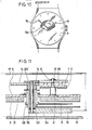
- a known clock with a silent alarm is shown in Figure 14.
- a vibration alarm 27, which may be placed under a pillow, has a case within which there is a vibration alarm motor 28.
- the motor 28 has an eccentric weight 29 on a rotary shaft of the motor.
- the vibration alarm 27 is separate from a clock 25 but is electrically connected to the clock 25 through a connection cord 26.
- the vibration alarm motor 28 is caused to rotate at an alarm set point time, and the vibration alarm 27 is vibrated by the centrifugal force of the eccentric weight 29 generated by the rotation thereof to let a person know the alarm time.
- the known wrist watches with a silent alarm which vibrate the skin of the user by means of a bar, a hammering member or a lever are restricted in external appearance, lack general applicability, and are liable to have a poor water-proof function. Furthermore, such wrist watches can produce an uncomfortable feeling in the person who wears them.
- a device of the kind shown in Figure 15 is fundamentally of the same kind as one that produces vibrations by means of a bar or the like; i.e. vibration is effected repetitively and very frequently at short intervals, so that problems the same as those mentioned above are involved.
- the hammering bar continuously strikes an impact receiving piece, whereby a knocking noise is generated which is not a silent alarm, and its durability is impaired.
- Such a watch moreover, has a large number of parts so that it is difficult to make it in a small size and in a reduced thickness.
- an alarm apparatus comprising a rotatably mounted eccentric weight; a motor for effecting rotation of the eccentric weight at an alarm time so as to cause vibration of the eccentric weight and thereby provide an alarm, and control means for operating the motor at the alarm time characterised in that the eccentric weight, the motor and the control means are all mounted in a common case.
- the motor is an ultrasonic wave motor, e.g. a motor which comprises a vibrator having a piezo-electric element fixed thereto for generating a surface wave thereon which is arranged to drive the eccentric weight.
- the eccentric weight may be in contact with the vibrator and pressurizing means may be provided for urging the eccentric weight against the vibrator.
- the vibrator may drive a rotor, the rotor driving the eccentric weight by way of gearing.
- the eccentric weight may be mounted for rotation about an axis which is radially spaced from that of the rotor.
- the apparatus may have time indicating hands which are concentric with the axis of the eccentric weight.
- the eccentric weight constitutes or forms part of a time indicating hand of the apparatus.
- Means may be provided to allow the eccentric weight to be seen from the exterior of the case.
- the apparatus is a wrist watch.
- An alarm apparatus may thus be provided in a small size and in a reduced thickness. It may also have highly efficient vibration which is generated with a small amount of drive energy.
- the alarm provided by the apparatus may also be a visual one.
- the case of the apparatus is preferably such that it can be held in the palm of a hand.
- the case may have a pin therein and the motor may include a vibrator supported by the pin and having a piezo-electric element bonded thereon for generating a surface wave thereon, there being an eccentric weight wheel having its centre of gravity spaced from its rotational axis and driven by the surface wave.
- the case may have a main plate therein, the pin being fixed in the main plate.
- the eccentric weight wheel may, if desired, be supported by the pin.
- the apparatus may comprise a rotor which is in contact with the vibrator and is rotated by the surface wave.
- the eccentric weight wheel may be disposed adjacent a glass and the vibrator of the ultrasonic motor may be disposed adjacent a back cover.
- a portion of the eccentric weight may be viewable through a display portion.
- FIG. 1 there is shown an apparatus according to the present invention which is constituted by a wrist watch.
- the wrist watch of Figure 1 has a vibrator 1 which has a piezo-electric element 2 fixed thereon and which is supported by a pin 4 that is mounted in a vibrator support plate 3.
- the piezo-electric element 2 is adapted to generate a surface wave in the vibrator 1.
- An eccentric weight wheel 5 is mounted for rotation about the pin 4 as a centre and has a semi-circular arcuate eccentric weight portion 5a disposed radially outwardly of comb teeth 1a of the vibrator 1.
- the eccentric weight wheel 5 is urged into contact with the comb teeth 1a of the vibrator 1 by a pressurizing spring 6.
- the pressurizing spring 6 is held by a holding washer 7 which is secured to the pin 4 by a screw 8.
- the eccentric weight wheel 5, which is adapted to be driven by the said surface wave works as a rotor of an ultrasonic wave motor.
- Figure 2 shows a plan view of the eccentric weight wheel 5.
- the eccentric weight wheel 5 has a substantially semi-circular arcuate shape.
- eccentric weight wheel 5 has an arcuate fan shape to produce the same effects as those of the semi-circular weight.
- the eccentric weight wheel 5 extends through a hole 9a formed in a dial plate 9 so as to extend in the direction of a watch glass 10.
- the vibrator support plate 3 is secured to a main plate 11 by the screw 8a.
- a back cover 17 is the same as that of an ordinary timepiece, the back cover 17 and the glass 10 defining the case of the wrist watch.
- Disposed within the said case 10, 17 of the wrist watch are electronic means (not shown) for driving the hands 15, 16 so as to indicate the present time and for transmitting an electrical signal to the piezo-electric element 2 so as to cause vibration of the latter at a selected alarm time.
- Means (not shown) are disposed within the case 10, 17 for detecting coincidence between an alarm time (which is set by means not shown) and the present time and for transmitting the said electrical signal when such coincidence occurs.
- Figure 4 is an external plan view of the wrist watch of Figure 1.
- the dial plate 9 has a viewing window 9b in the lower portion thereof
- the eccentric weight wheel 5 is located in the window 9b and may be viewed through it.
- the vibrator 1 In operation, when an electrical signal is applied to the piezo-electric element 2, the vibrator 1 undergoes mechanical vibration which causes the eccentric weight wheel 5 to rotate. Therefore, the centre of gravity G of the eccentric weight portion 5a, whose position is spaced from the axis of rotation of the eccentric weight wheel 5, causes the whole wrist watch to be vibrated by the reaction and the energy of vibration is transmitted to the wrist of the user to provide an alarm. In this case, the wrist watch is vibrated as a result of the rotation of the eccentric weight wheel 5.
- the back cover 17, which is in contact with the wrist of the user, is substantially fixed in position and a large amplitude is therefore produced in the direction of the glass 10.
- the moment for producing the vibration becomes greater in the direction of the glass 10 as the distance between the eccentric weight wheel 5 and the back cover 17 increases.
- the distance between the back cover 17 and the centre of gravity G of the eccentric weight portion 5a is denoted by h
- H » h the vibration is generated efficiently.
- an ultrasonic wave motor which is used as a drive source is constituted by stacked plate-like members in contrast to an ordinary cylindrical electromagnetic motor.
- Such an ultrasonic wave motor therefore has a reduced thickness such that the wrist watch itself can be given a reduced thickness. Furthermore, the ratio H/h becomes great, so enabling the vibration efficiency to be improved.
- the drive source need not be limited to an ultrasonic motor but may be an ordinary electromagnetic motor in which the same effect can be produced of bringing the eccentric weight portion 5a close to the dial plate 9.
- the motion of the eccentric weight wheel 5 cannot be seen from the exterior of the wrist watch when it is contained in the movement. As shown in Figures 1 and 4, however, the motion of the eccentric weight wheel 5 can be seen directly if it is located on the front side of the dial plate 9. The alarm therefore can be provided visually in addition to being provided in the form of vibration.
- Figures 5 and 6 illustrate another embodiment of the present invention wherein a pin 4 is driven into a main plate 11c and is secured thereby.
- the vibrator 1, on which the piezo-electric element 2 is fixed, is secured to the pin 4c.
- a transmission wheel support member 23, which rotatably supports a transmission wheel 22 by means of a wheel guide pin 24, is fitted to the pin 4c in order to rotatably support a rotor 18.
- the rotor 18 has a gear portion 18a that meshes with the transmission wheel 22.
- the rotor 18 is supported by a pressurizing spring 6c which is urged into contact with a comb-toothed portion 1a of the vibrator 1.
- the pin 4c rotatably supports an eccentric weight wheel 5 which is retained in position by a washer 19 mounted on a reduced diameter portion 4a of the pin 4c.
- the eccentric weight wheel 5 has a gear 5c engaging with the transmission wheel 22, the centre of gravity of an eccentric weight portion 5a of the wheel 5 being spaced from the axis of rotation of the latter.
- the piezo-electric element 2 In operation when the alarm is to be operated, the piezo-electric element 2 is vibrated due to an electric current that is transmitted thereto. The vibration that is generated in the piezo-electric element 2 is then transmitted to the vibrator 1 and is amplified by a comb-toothed portion 1a thereof.
- the rotor 18 is rotated by the comb-toothed portion 1a with the support pin 4c acting as a centre of rotation, and the transmission wheel 22 is rotated by a gear formed on the rotor 18.
- the transmission wheel 22 causes the eccentric weight wheel 5 to rotate about the pin 4c as a centre of rotation.
- the unbalanced centrifugal force produced by the rotation of the eccentric weight wheel 5 is transmitted through the main plate 11c to vibrate the whole timepiece.
- the wheel train 18a, 22, 5c in this case increases the speed of rotation; i.e. the number of revolutions of the eccentric weight wheel 5 is increased and the unbalanced centrifugal force can be increased.
- FIG. 7 Another embodiment of the present invention is shown in Figures 7 and 8.
- the vibrator 1 on which the piezo-electric element 2 is fixed is supported by a pin 4d which is mounted in a wheel train bridge 14d.
- a rotor 18d is in the form of a disc without an eccentric weight and is urged into contact with the vibrator 1 by a pressurizing spring 6d mounted on a stop ring or washer 19d.
- a gear is formed along the periphery of the rotor 18d and is in mesh with an eccentric weight wheel 5d that is constituted by a shaft mounted separately from the pin 4d.
- the eccentric weight wheel 5d is supported by a main plate 11d and by the wheel train bridge 14d.
- a shaft portion 5b of the eccentric weight wheel 5d protrudes to the front of the watch and extends through a dial plate gd.
- an eccentric weight 15a that has a centre of gravity at a point G.
- the device is the same as that of Figures 1 and 2.
- the effects that are obtained are the same as those of the embodiment of Figure 1 without the need to form in the dial plate 9 a hole 9a whose size is greater than that of the eccentric weight 5a.
- the size of the hole in the dial plate 9d merely needs to be large enough for the shaft portion 5b to pass therethrough. Therefore, the dial plate 9 requires little processing and can be easily machined so as to provide a better appearance.
- the rotation is transmitted at an increased speed via gears, making it possible to generate stronger vibration.
- Figures 9 and 10 illustrate a further embodiment of the present invention.
- the hour wheel 12 and the minute wheel 13 are supported by the main plate 11 and by the wheel train bridge 14, and the hour hand 15 and the minute hand 16 are driven so as to indicate the time.
- a pin 4e is driven into the back of a plate 11e which is carried by the main plate 11 so as to support the vibrator 1 on which the piezo-electric element 2 is fixed.
- On the pin 4e is mounted a rotor 18e.
- a pressurizing spring 6e and a stop ring 19e are provided beneath the rotor 18e to urge the latter into contact with the vibrator 1.
- a gear is formed along the circumference of the rotor 18e and is in mesh with an eccentric weight wheel 5e.
- the eccentric weight wheel 5e is rotatably mounted on a centre pipe or tube 20 whcih is mounted in the main plate 11.
- the eccentric weight wheel 5 is held between the main plate 11 and the dial plate 9 by means of a dial washer 21.
- the eccentric weight wheel 5e has a tubular portion 15b which extends towards the front side of the watch and passes through the dial plate 9.
- the tubular portion 15b has at one end thereof an eccentric weight 5a that has a centre of gravity at a point G.
- the back cover 17 and the glass 10 are constituted in the same manner as those of ordinary wrist watches.
- FIG. 11 illustrates a still further embodiment of the present invention.
- a centre pipe or tube 20f is mounted in the wheel train bridge 14.
- a minute wheel 13 is mounted concentrically about the centre tube 20f
- an hour wheel 12f is mounted concentrically about the minute wheel 13f.
- the hour wheel 12f and minute wheel 13f are held between the wheel train bridge 14 and the main plate 11 by means of a dial washer 21.
- An eccentric weight wheel 5f is mounted on the inner periphery of the centre tube 120 and is supported by a stop ring 19f.
- a pin 4f is driven into the main plate 11 on the upper side thereof to support the vibrator 1 and to carry a rotor 18f.
- the rotor 18f and the eccentric weight wheel 5f are in mesh with each other via gears that are formed along the circumferences thereof.
- the watch is the same as that of Figure 5 and has the same advantages but the eccentric weight 5a is on the opposite side of the hour hand 15 and minute hand 16. Therefore, the alarm can be seen visually in an easily recognizable manner. Furthermore, the distance H between the back cover 17 and the eccentric weight 5a is increased, so contributing to an improvement in vibration efficiency.
- the motor 1, 2, 18f is disposed on the upper side of the main plate 11 and does not extend downwardly thereof. Therefore, the main plate 11 can be machined easily, so facilitating assembly.
- FIGS 12 and 13 illustrate yet a further embodiment of the present invention.
- An hour wheel 12g is in mesh with a rotor 18g of the wave motor, the rotor 18g being mounted on a pin 4g which is fixed in a plate 11g carried by the main plate 11.
- a minute wheel 13g is driven by a separately provided motor (not shown) for driving the hands, the hour wheel 12g and the minute wheel 13g being driven independently of each other.
- An hour hand 15g is secured to one end of the hour wheel 12g and is so shaped in plan that its centre of gravity is at a position G which is spaced from its axis of rotation as shown, for example, in Figure 13, in order to produce the effect of an eccentric weight. Usually, therefore, the time is indicated by the outer end of the hour hand 15g.
- the hour hand 15g When the alarm set point time is however, reached, there will be high speed rotation of the hour hand 15g to generate vibration which provides the alarm. After the alarm has been provided, the hour hand 15g once again indicates the time. In this case, a large amount of energy is required to drive the hour hand 15g which has a large moment of inertia. From the viewpoint of construction, however, the number of parts can be decreased and the thickness of the timepiece can also be greatly decreased.
- the watch of Figures 12 and 13 may employ an ordinary hour hand and a minute hand (not shown) which acts as an eccentric weight.
- the eccentric weight wheel is driven by the vibration of the vibrator to which a piezo-electric element is fixed,and the whole timepiece is vibrated by the unbalanced centrifugal force produced by the rotation of the rotor. Therefore, a wrist watch with a silent alarm is achieved which has a simplified construction, a small size and a reduced thickness. Moreover, the number of parts is decreased so as to reduce the manufacturing cost. Furthermore, the rotary shaft of the eccentric weight extends through the dial plate and the eccentric weight may be disposed on the front side of the dial plate, making it possible to transmit the energy of vibration to the wrist of the user while employing only a small amount of drive energy. Moreover, a visual alarm can also be provided so enabling a wrist watch with a silent alarm to exhibit greatly improved ability for letting the user be aware of the alarm.
- the apparatus of the present invention may also be constructed in credit card size form rather than in the form of a wrist watch so that it can be carried in the pocket.
Abstract
Description
- This invention relates to an alarm apparatus and, although the invention is not so restricted it relates more particularly to an electronic wrist watch having a silent alarm which generates vibration at an alarm time.
- A silent alarm is sometimes employed in a timepiece or pager. A known clock with a silent alarm is shown in Figure 14. A
vibration alarm 27, which may be placed under a pillow, has a case within which there is avibration alarm motor 28. Themotor 28 has aneccentric weight 29 on a rotary shaft of the motor. Thevibration alarm 27 is separate from aclock 25 but is electrically connected to theclock 25 through aconnection cord 26. Thevibration alarm motor 28 is caused to rotate at an alarm set point time, and thevibration alarm 27 is vibrated by the centrifugal force of theeccentric weight 29 generated by the rotation thereof to let a person know the alarm time. - On the other hand, a variety of wrist watches with a silent alarm have heretofore been proposed in which a bar, a hammering member or a lever produces vibrations which are imparted to the skin of a user to make the latter aware of the alarm time. For example, Japanese Utility Model Laid-Open Specification No. 188185/1982 discloses, as shown in Figure 15, a wrist watch of the vibration type in which a
hammering bar 30 is actuated by agear 33 or the like and animpact receiving piece 32 is directly coupled to avibration plate 31 which is struck repetitively to generate vibration which is imparted to the skin of the user at the alarm time. - The generation of vibration by rotating an eccentric weight has been employed in the case of clocks and pocket bells that have relatively large sizes as described above. However, such a system has not been previously used in wrist watches, and a practical construction therefor has also not been proposed since an alarm motor for generating vibration is bulky and extra space is required for the eccentric weight.
- The known wrist watches with a silent alarm which vibrate the skin of the user by means of a bar, a hammering member or a lever are restricted in external appearance, lack general applicability, and are liable to have a poor water-proof function. Furthermore, such wrist watches can produce an uncomfortable feeling in the person who wears them. Moreover, a device of the kind shown in Figure 15 is fundamentally of the same kind as one that produces vibrations by means of a bar or the like; i.e. vibration is effected repetitively and very frequently at short intervals, so that problems the same as those mentioned above are involved. In this case, furthermore, the hammering bar continuously strikes an impact receiving piece, whereby a knocking noise is generated which is not a silent alarm, and its durability is impaired. Such a watch, moreover, has a large number of parts so that it is difficult to make it in a small size and in a reduced thickness.
- According to the present invention, there is therefore provided an alarm apparatus comprising a rotatably mounted eccentric weight; a motor for effecting rotation of the eccentric weight at an alarm time so as to cause vibration of the eccentric weight and thereby provide an alarm, and control means for operating the motor at the alarm time characterised in that the eccentric weight, the motor and the control means are all mounted in a common case.
- Preferably the motor is an ultrasonic wave motor, e.g. a motor which comprises a vibrator having a piezo-electric element fixed thereto for generating a surface wave thereon which is arranged to drive the eccentric weight.
- The eccentric weight may be in contact with the vibrator and pressurizing means may be provided for urging the eccentric weight against the vibrator.
- Alternatively, the vibrator may drive a rotor, the rotor driving the eccentric weight by way of gearing.
- The eccentric weight may be mounted for rotation about an axis which is radially spaced from that of the rotor.
- The apparatus may have time indicating hands which are concentric with the axis of the eccentric weight.
- In one embodiment, the eccentric weight constitutes or forms part of a time indicating hand of the apparatus.
- Means may be provided to allow the eccentric weight to be seen from the exterior of the case.
- In its preferred form, the apparatus is a wrist watch.
- An alarm apparatus according to the present invention may thus be provided in a small size and in a reduced thickness. It may also have highly efficient vibration which is generated with a small amount of drive energy.
- The alarm provided by the apparatus may also be a visual one.
- The case of the apparatus is preferably such that it can be held in the palm of a hand.
- The case may have a pin therein and the motor may include a vibrator supported by the pin and having a piezo-electric element bonded thereon for generating a surface wave thereon, there being an eccentric weight wheel having its centre of gravity spaced from its rotational axis and driven by the surface wave.
- The case may have a main plate therein, the pin being fixed in the main plate.
- The eccentric weight wheel may, if desired, be supported by the pin.
- The apparatus may comprise a rotor which is in contact with the vibrator and is rotated by the surface wave.
- The eccentric weight wheel may be disposed adjacent a glass and the vibrator of the ultrasonic motor may be disposed adjacent a back cover.
- A portion of the eccentric weight may be viewable through a display portion.
- The invention is illustrated, merely by way of example, in the accompanying drawings, in which:-
- Figure 1 is a sectional view of a first embodiment of an alarm apparatus according to the present invention, constituted by a wrist watch having a silent alarm;
- Figure 2 is a plan view of an eccentric weight wheel forming part of the structure shown in Figure 1;
- Figure 3 is a plan view of another embodiment of the said eccentric weight wheel of Figure 1;
- Figure 4 is an external plan view of the wrist watch of Figure 1;
- Figure 5 is a sectional view of a wrist watch with a silent alarm which constitutes a second embodiment of the present invention;
- Figure 6 is a plan view of an eccentric weight wheel forming part of the structure shown in Figure 5;
- Figure 7 is a sectional view of a wrist watch with a silent alarm which constitutes a third embodiment of the present invention;
- Figure 8 is an external plan view of the wrist watch of Figure 7;
- Figure 9 is a sectional view of a wrist watch with a silent alarm which constitutes a fourth embodiment of the present invention;
- Figure 10 is an external plan view of the wrist watch of Figure 9.
- Figure 11 is a sectional view of a wrist watch with a silent alarm which constitutes a fifth embodiment of the present invention;
- Figure 12 is a sectional view of a wrist watch with a silent alarm which constitutes a sixth embodiment of the present invention;
- Figure 13 is an external plan view of the wrist watch of Figure 12;
- Figure 14 is a perspective view of a known clock provided with a silent alarm; and
- Figure 15 is a partial sectional view of a known wrist watch provided with a silent alarm.
- In Figure 1 there is shown an apparatus according to the present invention which is constituted by a wrist watch. The wrist watch of Figure 1 has a
vibrator 1 which has a piezo-electric element 2 fixed thereon and which is supported by a pin 4 that is mounted in a vibrator support plate 3. The piezo-electric element 2 is adapted to generate a surface wave in thevibrator 1. Aneccentric weight wheel 5 is mounted for rotation about the pin 4 as a centre and has a semi-circular arcuateeccentric weight portion 5a disposed radially outwardly ofcomb teeth 1a of thevibrator 1. Theeccentric weight wheel 5 is urged into contact with thecomb teeth 1a of thevibrator 1 by a pressurizingspring 6. The pressurizingspring 6 is held by aholding washer 7 which is secured to the pin 4 by ascrew 8. Theeccentric weight wheel 5, which is adapted to be driven by the said surface wave, works as a rotor of an ultrasonic wave motor. - Figure 2 shows a plan view of the
eccentric weight wheel 5. Theeccentric weight wheel 5 has a substantially semi-circular arcuate shape. - Another eccentric weight wheel is shown in Figure 3. In this embodiment, the
eccentric weight wheel 5 has an arcuate fan shape to produce the same effects as those of the semi-circular weight. - Returning to Figure 1, the
eccentric weight wheel 5 extends through ahole 9a formed in adial plate 9 so as to extend in the direction of awatch glass 10. The vibrator support plate 3 is secured to amain plate 11 by the screw 8a. Anhour wheel 12 and aminute wheel 13, which are supported by themain plate 11 and by awheel train bridge 14, are provided with anhour hand 15 and aminute hand 16, respectively. Aback cover 17 is the same as that of an ordinary timepiece, theback cover 17 and theglass 10 defining the case of the wrist watch. - Disposed within the said
case hands electric element 2 so as to cause vibration of the latter at a selected alarm time. Means (not shown) are disposed within thecase - Figure 4 is an external plan view of the wrist watch of Figure 1. The
dial plate 9 has a viewing window 9b in the lower portion thereof Theeccentric weight wheel 5 is located in the window 9b and may be viewed through it. - In operation, when an electrical signal is applied to the piezo-
electric element 2, thevibrator 1 undergoes mechanical vibration which causes theeccentric weight wheel 5 to rotate. Therefore, the centre of gravity G of theeccentric weight portion 5a, whose position is spaced from the axis of rotation of theeccentric weight wheel 5, causes the whole wrist watch to be vibrated by the reaction and the energy of vibration is transmitted to the wrist of the user to provide an alarm. In this case, the wrist watch is vibrated as a result of the rotation of theeccentric weight wheel 5. Theback cover 17, which is in contact with the wrist of the user, is substantially fixed in position and a large amplitude is therefore produced in the direction of theglass 10. Therefore, the moment for producing the vibration becomes greater in the direction of theglass 10 as the distance between theeccentric weight wheel 5 and theback cover 17 increases. When the distance between theback cover 17 and the centre of gravity G of theeccentric weight portion 5a is denoted by h, in the case when theeccentric weight portion 5a is contained in the movement and the distance in the case of this device is denoted by H,
H » h
and the vibration is generated efficiently. - In the embodiment of Figures 1-4, an ultrasonic wave motor which is used as a drive source is constituted by stacked plate-like members in contrast to an ordinary cylindrical electromagnetic motor. Such an ultrasonic wave motor therefore has a reduced thickness such that the wrist watch itself can be given a reduced thickness. Furthermore, the ratio H/h becomes great, so enabling the vibration efficiency to be improved. However, the drive source need not be limited to an ultrasonic motor but may be an ordinary electromagnetic motor in which the same effect can be produced of bringing the
eccentric weight portion 5a close to thedial plate 9. The motion of theeccentric weight wheel 5 cannot be seen from the exterior of the wrist watch when it is contained in the movement. As shown in Figures 1 and 4, however, the motion of theeccentric weight wheel 5 can be seen directly if it is located on the front side of thedial plate 9. The alarm therefore can be provided visually in addition to being provided in the form of vibration. - Figures 5 and 6 illustrate another embodiment of the present invention wherein a pin 4 is driven into a
main plate 11c and is secured thereby. Thevibrator 1, on which the piezo-electric element 2 is fixed, is secured to thepin 4c. A transmissionwheel support member 23, which rotatably supports atransmission wheel 22 by means of awheel guide pin 24, is fitted to thepin 4c in order to rotatably support a rotor 18. The rotor 18 has agear portion 18a that meshes with thetransmission wheel 22. The rotor 18 is supported by a pressurizing spring 6c which is urged into contact with a comb-toothed portion 1a of thevibrator 1. Thepin 4c rotatably supports aneccentric weight wheel 5 which is retained in position by awasher 19 mounted on a reduceddiameter portion 4a of thepin 4c. Theeccentric weight wheel 5 has agear 5c engaging with thetransmission wheel 22, the centre of gravity of aneccentric weight portion 5a of thewheel 5 being spaced from the axis of rotation of the latter. - In operation when the alarm is to be operated, the piezo-
electric element 2 is vibrated due to an electric current that is transmitted thereto. The vibration that is generated in the piezo-electric element 2 is then transmitted to thevibrator 1 and is amplified by a comb-toothed portion 1a thereof. The rotor 18 is rotated by the comb-toothed portion 1a with thesupport pin 4c acting as a centre of rotation, and thetransmission wheel 22 is rotated by a gear formed on the rotor 18. Thetransmission wheel 22 causes theeccentric weight wheel 5 to rotate about thepin 4c as a centre of rotation. The unbalanced centrifugal force produced by the rotation of theeccentric weight wheel 5 is transmitted through themain plate 11c to vibrate the whole timepiece. - Even when the timepiece has an increased weight as a whole, the
wheel train eccentric weight wheel 5 is increased and the unbalanced centrifugal force can be increased. - Another embodiment of the present invention is shown in Figures 7 and 8. In this embodiment, the
vibrator 1 on which the piezo-electric element 2 is fixed is supported by apin 4d which is mounted in awheel train bridge 14d. Arotor 18d is in the form of a disc without an eccentric weight and is urged into contact with thevibrator 1 by a pressurizingspring 6d mounted on a stop ring orwasher 19d. A gear is formed along the periphery of therotor 18d and is in mesh with aneccentric weight wheel 5d that is constituted by a shaft mounted separately from thepin 4d. Theeccentric weight wheel 5d is supported by amain plate 11d and by thewheel train bridge 14d. A shaft portion 5b of theeccentric weight wheel 5d protrudes to the front of the watch and extends through a dial plate gd. To an end portion of the shaft portion 5b there is secured aneccentric weight 15a that has a centre of gravity at a point G. In other respects, the device is the same as that of Figures 1 and 2. In this case, the effects that are obtained are the same as those of the embodiment of Figure 1 without the need to form in thedial plate 9 ahole 9a whose size is greater than that of theeccentric weight 5a. In the case of the Figure 7 construction, the size of the hole in the dial plate 9d merely needs to be large enough for the shaft portion 5b to pass therethrough. Therefore, thedial plate 9 requires little processing and can be easily machined so as to provide a better appearance. Furthermore, the rotation is transmitted at an increased speed via gears, making it possible to generate stronger vibration. - Figures 9 and 10 illustrate a further embodiment of the present invention. In this embodiment, the
hour wheel 12 and theminute wheel 13 are supported by themain plate 11 and by thewheel train bridge 14, and thehour hand 15 and theminute hand 16 are driven so as to indicate the time. A pin 4e is driven into the back of a plate 11e which is carried by themain plate 11 so as to support thevibrator 1 on which the piezo-electric element 2 is fixed. On the pin 4e is mounted arotor 18e. A pressurizingspring 6e and astop ring 19e are provided beneath therotor 18e to urge the latter into contact with thevibrator 1. A gear is formed along the circumference of therotor 18e and is in mesh with aneccentric weight wheel 5e. Theeccentric weight wheel 5e is rotatably mounted on a centre pipe ortube 20 whcih is mounted in themain plate 11. Theeccentric weight wheel 5 is held between themain plate 11 and thedial plate 9 by means of adial washer 21. Theeccentric weight wheel 5e has atubular portion 15b which extends towards the front side of the watch and passes through thedial plate 9. Thetubular portion 15b has at one end thereof aneccentric weight 5a that has a centre of gravity at a point G. Theback cover 17 and theglass 10 are constituted in the same manner as those of ordinary wrist watches. - The watch of Figures 9 and 10 works similarly to that of Figure 1. However, since the
eccentric weight wheel 5e is provieed concentrically with thehand wheels - Figure 11 illustrates a still further embodiment of the present invention. In this embodiment, a centre pipe or
tube 20f is mounted in thewheel train bridge 14. Aminute wheel 13 is mounted concentrically about thecentre tube 20f, and anhour wheel 12f is mounted concentrically about the minute wheel 13f. Thehour wheel 12f and minute wheel 13f are held between thewheel train bridge 14 and themain plate 11 by means of adial washer 21. Aneccentric weight wheel 5f is mounted on the inner periphery of the centre tube 120 and is supported by astop ring 19f. A pin 4f is driven into themain plate 11 on the upper side thereof to support thevibrator 1 and to carry a rotor 18f. The rotor 18f and theeccentric weight wheel 5f are in mesh with each other via gears that are formed along the circumferences thereof. In other respects, the watch is the same as that of Figure 5 and has the same advantages but theeccentric weight 5a is on the opposite side of thehour hand 15 andminute hand 16. Therefore, the alarm can be seen visually in an easily recognizable manner. Furthermore, the distance H between theback cover 17 and theeccentric weight 5a is increased, so contributing to an improvement in vibration efficiency. Themotor main plate 11 and does not extend downwardly thereof. Therefore, themain plate 11 can be machined easily, so facilitating assembly. - Figures 12 and 13 illustrate yet a further embodiment of the present invention. An hour wheel 12g is in mesh with a rotor 18g of the wave motor, the rotor 18g being mounted on a
pin 4g which is fixed in a plate 11g carried by themain plate 11. A minute wheel 13g is driven by a separately provided motor (not shown) for driving the hands, the hour wheel 12g and the minute wheel 13g being driven independently of each other. An hour hand 15g is secured to one end of the hour wheel 12g and is so shaped in plan that its centre of gravity is at a position G which is spaced from its axis of rotation as shown, for example, in Figure 13, in order to produce the effect of an eccentric weight. Usually, therefore, the time is indicated by the outer end of the hour hand 15g. When the alarm set point time is however, reached, there will be high speed rotation of the hour hand 15g to generate vibration which provides the alarm. After the alarm has been provided, the hour hand 15g once again indicates the time. In this case, a large amount of energy is required to drive the hour hand 15g which has a large moment of inertia. From the viewpoint of construction, however, the number of parts can be decreased and the thickness of the timepiece can also be greatly decreased. - Alternatively, the watch of Figures 12 and 13 may employ an ordinary hour hand and a minute hand (not shown) which acts as an eccentric weight.
- In the embodiments described above, the eccentric weight wheel is driven by the vibration of the vibrator to which a piezo-electric element is fixed,and the whole timepiece is vibrated by the unbalanced centrifugal force produced by the rotation of the rotor. Therefore, a wrist watch with a silent alarm is achieved which has a simplified construction, a small size and a reduced thickness. Moreover, the number of parts is decreased so as to reduce the manufacturing cost. Furthermore, the rotary shaft of the eccentric weight extends through the dial plate and the eccentric weight may be disposed on the front side of the dial plate, making it possible to transmit the energy of vibration to the wrist of the user while employing only a small amount of drive energy. Moreover, a visual alarm can also be provided so enabling a wrist watch with a silent alarm to exhibit greatly improved ability for letting the user be aware of the alarm.
- The apparatus of the present invention may also be constructed in credit card size form rather than in the form of a wrist watch so that it can be carried in the pocket.
Claims (12)
a case capable of being held on the palm of a hand;
time counting means in said case for counting a present time;
alarm time setting means for setting alarm time in response to a user operation;
ultrasonic motor in said case having an eccentric weight for generating vibration;
alarm time detection means for detecting a coincidence a present time with the alarm time set by said alarm time setting means;
driving means for driving said ultrasonic motor in accordance with said detection of the coincidence.
Applications Claiming Priority (4)
| Application Number | Priority Date | Filing Date | Title |
|---|---|---|---|
| JP85405/88U | 1988-06-27 | ||
| JP8540588U JPH0720633Y2 (en) | 1988-06-27 | 1988-06-27 | Vibration generator and alarm clock |
| JP1989015692U JPH0717037Y2 (en) | 1989-02-13 | 1989-02-13 | Watch with vibration alarm |
| JP15692/89U | 1989-02-13 |
Publications (3)
| Publication Number | Publication Date |
|---|---|
| EP0349230A2 true EP0349230A2 (en) | 1990-01-03 |
| EP0349230A3 EP0349230A3 (en) | 1991-03-27 |
| EP0349230B1 EP0349230B1 (en) | 1994-08-24 |
Family
ID=26351880
Family Applications (1)
| Application Number | Title | Priority Date | Filing Date |
|---|---|---|---|
| EP89306433A Expired - Lifetime EP0349230B1 (en) | 1988-06-27 | 1989-06-26 | Alarm apparatus |
Country Status (3)
| Country | Link |
|---|---|
| US (1) | US5023853A (en) |
| EP (1) | EP0349230B1 (en) |
| DE (1) | DE68917656T2 (en) |
Cited By (7)
| Publication number | Priority date | Publication date | Assignee | Title |
|---|---|---|---|---|
| EP0405853A2 (en) * | 1989-06-26 | 1991-01-02 | Seiko Instruments Inc. | Wrist watch with oscillation alarm |
| EP0547250A1 (en) * | 1991-07-05 | 1993-06-23 | Citizen Watch Co. Ltd. | Timepiece equipped with silent alarm |
| US5365497A (en) * | 1993-05-18 | 1994-11-15 | Asulab S.A. | Silent electromagnetic alarm |
| EP0710899A1 (en) | 1994-11-03 | 1996-05-08 | Asulab S.A. | Watch with time indication by non-sonic vibrations |
| US6540396B1 (en) | 1999-06-23 | 2003-04-01 | Eta Sa Fabriques D'ebauches | Watch including an additional electric apparatus |
| WO2003062930A1 (en) * | 2002-01-25 | 2003-07-31 | Rudolf Junod | Device for reproducing a clock pulse frequency |
| EP4325304A1 (en) | 2022-08-15 | 2024-02-21 | The Swatch Group Research and Development Ltd | Electromagnetic silent alarm |
Families Citing this family (24)
| Publication number | Priority date | Publication date | Assignee | Title |
|---|---|---|---|---|
| US5089998A (en) * | 1991-04-04 | 1992-02-18 | Richard Rund | Vibrating and audible alarm clock |
| US5282181A (en) * | 1991-08-23 | 1994-01-25 | Shelly Karen Entner | Silent alarm timepiece |
| EP0585470B1 (en) * | 1992-03-18 | 1997-09-10 | Citizen Watch Co. Ltd. | Electronic machine with vibration alarm |
| JPH05281370A (en) * | 1992-03-31 | 1993-10-29 | Seiko Instr Inc | Analog electronic timepiece |
| CH685660B5 (en) * | 1992-09-09 | 1996-03-15 | Asulab Sa | Timepiece provided with drive means forms by a piezoelectric motor. |
| US5666331A (en) * | 1994-09-20 | 1997-09-09 | Rhk Technology, Inc. | Alarm clock |
| US5861797A (en) * | 1997-07-18 | 1999-01-19 | Becker; Laurence D. | Tactile reminder device & method |
| US6724298B2 (en) | 2001-08-07 | 2004-04-20 | J. Michelle Smith | Individual discreet prompting device with remote |
| US7050360B2 (en) * | 2002-03-20 | 2006-05-23 | Kabushiki-Kaisya Tokyo Shinya | Wrist watch with vibration function |
| US6727419B1 (en) * | 2002-12-03 | 2004-04-27 | Manuel Diaz | Pulsating metronome |
| JP3790523B2 (en) * | 2003-06-19 | 2006-06-28 | 志豐電子股▲分▼有限公司 | Piezoelectric push-pull ultrasonic motor |
| WO2006070369A2 (en) * | 2004-12-30 | 2006-07-06 | Given Imaging Ltd. | Device, system and method for orienting a sensor in-vivo |
| US20060274609A1 (en) * | 2005-06-06 | 2006-12-07 | Lindsey Glenn E Sr | Silent alarm wrist watch |
| US7751284B2 (en) * | 2005-07-06 | 2010-07-06 | Edison Nation, Llc | Self-moving alarm clock |
| US20090040874A1 (en) * | 2007-08-08 | 2009-02-12 | Rooney World Corp. | Medication Reminder System and Method |
| US9128828B2 (en) | 2012-05-02 | 2015-09-08 | Gauss Spire Llc | Exam notification timer device |
| US8233355B2 (en) | 2008-08-08 | 2012-07-31 | Edison Nation, Llc | Alarm device |
| ATE498860T1 (en) * | 2008-12-01 | 2011-03-15 | Swatch Group Res & Dev Ltd | CLOCK MOVEMENT EQUIPPED WITH A VIBRATION ALARM |
| EP2339413B1 (en) * | 2009-12-22 | 2012-09-12 | The Swatch Group Research and Development Ltd. | Timepiece movement equipped with a vibrating alarm |
| JP5817328B2 (en) * | 2011-08-22 | 2015-11-18 | カシオ計算機株式会社 | Clock module and electronic equipment |
| US8699306B2 (en) | 2011-12-28 | 2014-04-15 | Gauss Spire Llc | Silent alarm and exam notification timer device |
| US9069333B1 (en) | 2012-08-14 | 2015-06-30 | Natascha Romans | Personal alarm watch |
| KR101680600B1 (en) * | 2014-06-26 | 2016-11-30 | 주식회사 모아텍 | Actuator and electronic equipmenthaving the same |
| US9830783B1 (en) | 2014-09-24 | 2017-11-28 | Apple Inc. | Output devices for fabric-based electronic equipment |
Citations (8)
| Publication number | Priority date | Publication date | Assignee | Title |
|---|---|---|---|---|
| US3748845A (en) * | 1971-12-02 | 1973-07-31 | Bulova Watch Co Inc | Electronic system module for crystal-controlled watch |
| US4028882A (en) * | 1976-02-19 | 1977-06-14 | Muncheryan Hrand M | Awakening system with means adapted to relax tense muscles |
| US4456387A (en) * | 1978-12-18 | 1984-06-26 | Kazunobu Igarashi | Electronic alarm wrist watch |
| JPS6089791A (en) * | 1983-10-24 | 1985-05-20 | Seikosha Co Ltd | Alarm wrist watch |
| JPS60111178A (en) * | 1983-11-21 | 1985-06-17 | Seiko Epson Corp | Pointer display type electronic timepiece |
| WO1987005166A1 (en) * | 1986-02-18 | 1987-08-27 | Matsushita Electric Industrial Co., Ltd. | Ultrasonic motor |
| US4723085A (en) * | 1985-03-29 | 1988-02-02 | Canon Kabushiki Kaisha | Vibration wave motor |
| US4727276A (en) * | 1985-03-26 | 1988-02-23 | Canon Kabushiki Kaisha | Driving circuit for vibration wave motor |
Family Cites Families (1)
| Publication number | Priority date | Publication date | Assignee | Title |
|---|---|---|---|---|
| JP2595950B2 (en) * | 1987-01-27 | 1997-04-02 | 松下電器産業株式会社 | Ultrasonic motor drive |
-
1989
- 1989-06-22 US US07/369,732 patent/US5023853A/en not_active Expired - Lifetime
- 1989-06-26 DE DE68917656T patent/DE68917656T2/en not_active Expired - Fee Related
- 1989-06-26 EP EP89306433A patent/EP0349230B1/en not_active Expired - Lifetime
Patent Citations (8)
| Publication number | Priority date | Publication date | Assignee | Title |
|---|---|---|---|---|
| US3748845A (en) * | 1971-12-02 | 1973-07-31 | Bulova Watch Co Inc | Electronic system module for crystal-controlled watch |
| US4028882A (en) * | 1976-02-19 | 1977-06-14 | Muncheryan Hrand M | Awakening system with means adapted to relax tense muscles |
| US4456387A (en) * | 1978-12-18 | 1984-06-26 | Kazunobu Igarashi | Electronic alarm wrist watch |
| JPS6089791A (en) * | 1983-10-24 | 1985-05-20 | Seikosha Co Ltd | Alarm wrist watch |
| JPS60111178A (en) * | 1983-11-21 | 1985-06-17 | Seiko Epson Corp | Pointer display type electronic timepiece |
| US4727276A (en) * | 1985-03-26 | 1988-02-23 | Canon Kabushiki Kaisha | Driving circuit for vibration wave motor |
| US4723085A (en) * | 1985-03-29 | 1988-02-02 | Canon Kabushiki Kaisha | Vibration wave motor |
| WO1987005166A1 (en) * | 1986-02-18 | 1987-08-27 | Matsushita Electric Industrial Co., Ltd. | Ultrasonic motor |
Non-Patent Citations (2)
| Title |
|---|
| PATENT ABSTRACTS OF JAPAN, vol. 009-236 (P-390), 21st September 1985; & JP-A-60 89 791 (SEIKOUSHIYA K.K.) 20-05-1985 * |
| PATENT ABSTRACTS OF JAPAN, vol. 9, no. 262 (P-398)[1985], 19th October 1985; & JP-A-60 111 178 (SUWA SEIKOSHA K.K.) 17-06-1985 * |
Cited By (10)
| Publication number | Priority date | Publication date | Assignee | Title |
|---|---|---|---|---|
| EP0405853A2 (en) * | 1989-06-26 | 1991-01-02 | Seiko Instruments Inc. | Wrist watch with oscillation alarm |
| EP0405853A3 (en) * | 1989-06-26 | 1992-01-22 | Seiko Instruments Inc. | Wrist watch with oscillation alarm |
| EP0547250A1 (en) * | 1991-07-05 | 1993-06-23 | Citizen Watch Co. Ltd. | Timepiece equipped with silent alarm |
| EP0547250A4 (en) * | 1991-07-05 | 1993-12-08 | Citizen Watch Co. Ltd. | Timepiece equipped with silent alarm |
| US5365497A (en) * | 1993-05-18 | 1994-11-15 | Asulab S.A. | Silent electromagnetic alarm |
| EP0710899A1 (en) | 1994-11-03 | 1996-05-08 | Asulab S.A. | Watch with time indication by non-sonic vibrations |
| US5559761A (en) * | 1994-11-03 | 1996-09-24 | Asulab S.A. | Watch with time information VIA silent vibration |
| US6540396B1 (en) | 1999-06-23 | 2003-04-01 | Eta Sa Fabriques D'ebauches | Watch including an additional electric apparatus |
| WO2003062930A1 (en) * | 2002-01-25 | 2003-07-31 | Rudolf Junod | Device for reproducing a clock pulse frequency |
| EP4325304A1 (en) | 2022-08-15 | 2024-02-21 | The Swatch Group Research and Development Ltd | Electromagnetic silent alarm |
Also Published As
| Publication number | Publication date |
|---|---|
| EP0349230A3 (en) | 1991-03-27 |
| EP0349230B1 (en) | 1994-08-24 |
| US5023853A (en) | 1991-06-11 |
| DE68917656D1 (en) | 1994-09-29 |
| DE68917656T2 (en) | 1994-12-22 |
Similar Documents
| Publication | Publication Date | Title |
|---|---|---|
| EP0349230B1 (en) | Alarm apparatus | |
| US8305848B2 (en) | Timepiece movement fitted with an inertial coupling mechanism | |
| US4253177A (en) | Apparatus for manual adjustment of a clock | |
| US4910720A (en) | Watch having a visible energy producing oscillatory mass | |
| RU2342689C2 (en) | Animated clockwork | |
| JPH0717037Y2 (en) | Watch with vibration alarm | |
| JP4351448B2 (en) | Watch movement | |
| US5105398A (en) | Three hands type clock with belt drive | |
| US2821063A (en) | Clockwork mechanism | |
| US4203279A (en) | Timepiece which permits freely adjusting the level of sounds produced therein and given out thereof | |
| JPH1073671A (en) | Mechanical watch device assembled with stop watch | |
| EP0354194A1 (en) | A timepiece with an eccentric display module | |
| JP3691946B2 (en) | Clockwork clock with rotating decorative plate | |
| JPH0336945Y2 (en) | ||
| JPH0720633Y2 (en) | Vibration generator and alarm clock | |
| JPH044234Y2 (en) | ||
| JPH0540472Y2 (en) | ||
| EP0437033A2 (en) | Time keeping device with vibrational alarm | |
| US3555809A (en) | Long ringing kitchen timer | |
| JPH088474Y2 (en) | Generator watches and self-winding watches | |
| JPH0541426Y2 (en) | ||
| JPS6231902Y2 (en) | ||
| JPH0453596Y2 (en) | ||
| JPH01197688A (en) | Timepiece | |
| JPH11211861A (en) | Operating method for portable timer |
Legal Events
| Date | Code | Title | Description |
|---|---|---|---|
| PUAI | Public reference made under article 153(3) epc to a published international application that has entered the european phase |
Free format text: ORIGINAL CODE: 0009012 |
|
| AK | Designated contracting states |
Kind code of ref document: A2 Designated state(s): CH DE FR GB LI |
|
| PUAL | Search report despatched |
Free format text: ORIGINAL CODE: 0009013 |
|
| AK | Designated contracting states |
Kind code of ref document: A3 Designated state(s): CH DE FR GB LI |
|
| 17P | Request for examination filed |
Effective date: 19910618 |
|
| 17Q | First examination report despatched |
Effective date: 19920407 |
|
| GRAA | (expected) grant |
Free format text: ORIGINAL CODE: 0009210 |
|
| AK | Designated contracting states |
Kind code of ref document: B1 Designated state(s): CH DE FR GB LI |
|
| REF | Corresponds to: |
Ref document number: 68917656 Country of ref document: DE Date of ref document: 19940929 |
|
| ET | Fr: translation filed | ||
| REG | Reference to a national code |
Ref country code: GB Ref legal event code: 746 Effective date: 19950502 |
|
| PLBE | No opposition filed within time limit |
Free format text: ORIGINAL CODE: 0009261 |
|
| STAA | Information on the status of an ep patent application or granted ep patent |
Free format text: STATUS: NO OPPOSITION FILED WITHIN TIME LIMIT |
|
| 26N | No opposition filed | ||
| REG | Reference to a national code |
Ref country code: FR Ref legal event code: D6 |
|
| REG | Reference to a national code |
Ref country code: GB Ref legal event code: IF02 |
|
| PGFP | Annual fee paid to national office [announced via postgrant information from national office to epo] |
Ref country code: FR Payment date: 20060608 Year of fee payment: 18 |
|
| PGFP | Annual fee paid to national office [announced via postgrant information from national office to epo] |
Ref country code: GB Payment date: 20060621 Year of fee payment: 18 |
|
| PGFP | Annual fee paid to national office [announced via postgrant information from national office to epo] |
Ref country code: DE Payment date: 20060622 Year of fee payment: 18 |
|
| PGFP | Annual fee paid to national office [announced via postgrant information from national office to epo] |
Ref country code: CH Payment date: 20060628 Year of fee payment: 18 |
|
| REG | Reference to a national code |
Ref country code: CH Ref legal event code: PL |
|
| GBPC | Gb: european patent ceased through non-payment of renewal fee |
Effective date: 20070626 |
|
| REG | Reference to a national code |
Ref country code: FR Ref legal event code: ST Effective date: 20080229 |
|
| PG25 | Lapsed in a contracting state [announced via postgrant information from national office to epo] |
Ref country code: LI Free format text: LAPSE BECAUSE OF NON-PAYMENT OF DUE FEES Effective date: 20070630 Ref country code: DE Free format text: LAPSE BECAUSE OF NON-PAYMENT OF DUE FEES Effective date: 20080101 Ref country code: CH Free format text: LAPSE BECAUSE OF NON-PAYMENT OF DUE FEES Effective date: 20070630 |
|
| PG25 | Lapsed in a contracting state [announced via postgrant information from national office to epo] |
Ref country code: GB Free format text: LAPSE BECAUSE OF NON-PAYMENT OF DUE FEES Effective date: 20070626 |
|
| PG25 | Lapsed in a contracting state [announced via postgrant information from national office to epo] |
Ref country code: FR Free format text: LAPSE BECAUSE OF NON-PAYMENT OF DUE FEES Effective date: 20070702 |