EP0318748B2 - Apparatus for bending a hollow profile, in particular a frame of spacekeeping profiles for insulating glass panes - Google Patents
Apparatus for bending a hollow profile, in particular a frame of spacekeeping profiles for insulating glass panes Download PDFInfo
- Publication number
- EP0318748B2 EP0318748B2 EP88118909A EP88118909A EP0318748B2 EP 0318748 B2 EP0318748 B2 EP 0318748B2 EP 88118909 A EP88118909 A EP 88118909A EP 88118909 A EP88118909 A EP 88118909A EP 0318748 B2 EP0318748 B2 EP 0318748B2
- Authority
- EP
- European Patent Office
- Prior art keywords
- profile
- abutment
- bend
- bending
- area
- Prior art date
- Legal status (The legal status is an assumption and is not a legal conclusion. Google has not performed a legal analysis and makes no representation as to the accuracy of the status listed.)
- Expired - Lifetime
Links
Images


Classifications
-
- B—PERFORMING OPERATIONS; TRANSPORTING
- B21—MECHANICAL METAL-WORKING WITHOUT ESSENTIALLY REMOVING MATERIAL; PUNCHING METAL
- B21D—WORKING OR PROCESSING OF SHEET METAL OR METAL TUBES, RODS OR PROFILES WITHOUT ESSENTIALLY REMOVING MATERIAL; PUNCHING METAL
- B21D7/00—Bending rods, profiles, or tubes
- B21D7/02—Bending rods, profiles, or tubes over a stationary forming member; by use of a swinging forming member or abutment
-
- B—PERFORMING OPERATIONS; TRANSPORTING
- B21—MECHANICAL METAL-WORKING WITHOUT ESSENTIALLY REMOVING MATERIAL; PUNCHING METAL
- B21D—WORKING OR PROCESSING OF SHEET METAL OR METAL TUBES, RODS OR PROFILES WITHOUT ESSENTIALLY REMOVING MATERIAL; PUNCHING METAL
- B21D53/00—Making other particular articles
- B21D53/74—Making other particular articles frames for openings, e.g. for windows, doors, handbags
-
- E—FIXED CONSTRUCTIONS
- E06—DOORS, WINDOWS, SHUTTERS, OR ROLLER BLINDS IN GENERAL; LADDERS
- E06B—FIXED OR MOVABLE CLOSURES FOR OPENINGS IN BUILDINGS, VEHICLES, FENCES OR LIKE ENCLOSURES IN GENERAL, e.g. DOORS, WINDOWS, BLINDS, GATES
- E06B3/00—Window sashes, door leaves, or like elements for closing wall or like openings; Layout of fixed or moving closures, e.g. windows in wall or like openings; Features of rigidly-mounted outer frames relating to the mounting of wing frames
- E06B3/66—Units comprising two or more parallel glass or like panes permanently secured together
- E06B3/673—Assembling the units
- E06B3/67304—Preparing rigid spacer members before assembly
- E06B3/67308—Making spacer frames, e.g. by bending or assembling straight sections
- E06B3/67313—Making spacer frames, e.g. by bending or assembling straight sections by bending
-
- Y—GENERAL TAGGING OF NEW TECHNOLOGICAL DEVELOPMENTS; GENERAL TAGGING OF CROSS-SECTIONAL TECHNOLOGIES SPANNING OVER SEVERAL SECTIONS OF THE IPC; TECHNICAL SUBJECTS COVERED BY FORMER USPC CROSS-REFERENCE ART COLLECTIONS [XRACs] AND DIGESTS
- Y10—TECHNICAL SUBJECTS COVERED BY FORMER USPC
- Y10T—TECHNICAL SUBJECTS COVERED BY FORMER US CLASSIFICATION
- Y10T29/00—Metal working
- Y10T29/51—Plural diverse manufacturing apparatus including means for metal shaping or assembling
- Y10T29/5199—Work on tubes
Definitions
- the invention relates to a device for bending a hollow profile - preferably for producing a high spacer frame for insulating glass panes, in particular filled with desiccant - according to the preamble of patent claim 1.
- Such a device is known from EP-A-121873 and DE-A-33 12 764 and has proven particularly useful for profiles with sufficient wall thickness.
- the outside of the bend can be elongated and stretched by the tool which can be pressed there, preferably a roller or roller, this roller being able to be moved back and forth at high frequency under certain circumstances.
- This combination of features and measures means that the two webs delimiting the inner and outer corners of the curved profile are clamped during the critical phase of the bend between the abutment and the tool on the one hand and between the side walls of the profile on the other hand, because of the aforementioned Dimensions the tool that acts on the outside of the profile, while pressing in the outer profile wall that it applies, dip between the side webs of the profile and without cracking or warping this outer wall can deform into the interior of the profile, where a corresponding Shorter bending path is given, a part of this outer wall and / or also the side wall can be folded inwards relative to the standing side wall and this can be approximated more or less.
- the abutment and the web acted upon by it can also be deformed somewhat between the side walls of the profile.
- a controlled bending of a very thin-walled profile can also be carried out without the webs or walls being able to move in an undesired direction, but also rolling or routes are not required or at most only to a small extent.
- a desiccant intermediate layer which is preferably reduced in its extent, can be provided between these mutually facing surfaces if the hollow profile is at least partially filled with desiccant from the outset. Since desiccant generally reacts in a sand-like manner, a very good support of the two webs against one another can also be achieved, although a desiccant-free bend is preferred if the webs are as precisely as possible in a specific position relative to the side walls deformed and supported directly against each other. This is especially true when the two webs are to be brought as close as possible to the neutral fiber of the profile.
- the pressure roller serving as a tool can be bevelled circumferentially on its side surfaces near its circumference, which acts as a working surface, and the greater width of the pressure roller can be equal to or less than the inside clearance of the side walls of the profile, while the narrower area of the pressure roller has a width that is approximately the same as the width can correspond to a web area on the outside of the profile, from each of which inclined web areas fall off towards the side walls.
- Such an embodiment of the device is particularly suitable for bending hollow profiles with a cross section that is at least approximately trapezoidal in the outer region.
- the sloping side wall areas then do not have to be acted upon directly by the working surface of the pressure roller in order to be able to be pressed in gradually until the outer wall area is touched by the inner web of the profile which is subjected to the abutment.
- the bevels on the side surfaces of the bending or pressure roller can have a radial width that is equal to or greater than the immersion depth of the bending roller when bending and pressing the outer web in the direction of the abutment.
- These bevels on the side surfaces of the tool have the advantage that a too sharp bending of the outer web relative to the side webs or side walls is avoided because the inwardly bent edge web area can remain somewhat oblique with respect to the outer web.
- the abutment located on the inside of the bend is a shaped piece, the outer contour of which corresponds to the inner contour of the inner bend to be produced, and which at least at times during the bending compared to the two inner sides which are at an angle to one another after the bending, or the frame legs are in the direction of the outer side of the bend and the profile protrudes so that the inside of the bend receives an indentation.
- the inside of the bend practically accommodates the outside pressed in from the outside during the bending process, so that the two webs occur at least temporarily during the bending to be able to touch, support and lead each other, especially during the most important and critical phase.
- the abutment or the fitting serving as an abutment can be used to adapt to different profiles, web thicknesses, web shapes or the like. be interchangeable.
- One way of optimizing the bending process and the deformation of the inner web in particular can be that the abutment during the bending process, in particular controlled, can be moved or moved deeper into the bend than it is arranged in its starting position.
- the increasing bend is accompanied by a greater indentation of the inside of the bend.
- Embodiments and modifications of the abutment and various options for how the abutment can be moved more and more into the bend during the bending process are the subject of claims 8 to 15.
- some claims relate to a solution in which the abutment can be pivoted in proportion to the bending process , so that its outside pulls the inside of the profile to a certain extent and, in particular in the exemplary embodiments in which the abutment has a projection that increases in size in the pivoting direction, practically "rolls" into the inside of the profile to be bent and into the inside bend.
- some of the claims mentioned also relate to solutions in which the abutment is pressed deeper and deeper into the inner bend in proportion to the progress of the bend without being pivoted.
- Claims 16 and 19 relate above all to the hold-down device or hold-down devices, which hold the side surfaces of the hollow profile to the correct extent during the bending process and avoid warping and deformation in these areas, which could lead to a distortion of the external distance.
- Claims 19 to 23 relate to configurations which allow the use of the bending device according to the invention and in particular the compression of the inner and outer walls and webs even in the case of profiles filled with desiccant, in that the bending area is at least temporarily freed from drying agent, preferably with the aid of compressed air .
- a device designated overall by 1 in all exemplary embodiments serves for bending a hollow profile 2, it being indicated above all in FIG. 6 that this can involve the production of a hollow spacer frame filled with desiccant 3 for insulating glass panes.
- the profile 2 could be bent four times if the frame is to consist of a single piece. The two profile ends could then butt against one another and be joined on one long side.
- a tensioning device 4 is provided on the device 1 for detecting the profile area located before the bend. Furthermore, the device 1 has a device 5 for grasping the leg to be bent and an abutment 6 for fixing the inside of the bend or curvature that arises. It is also indicated in FIGS. 1, 6 and 7 and in FIGS. 2, 3 and 7. 8 shows in more detail that on the outside of the bending point a tool that can be moved under contact pressure relative to the abutment 6 and can be pressed onto the outside of the profile, in the exemplary embodiment in the form of at least part of the pressure roller or roller acting on the profile web 7 located on the outside of the bend 8 is provided, which in Figures 1, 6 u.
- the clear distance between the tool 8 engaging on the outside of the resulting bend of the profile 2 and the abutment 6 on the other hand, as is particularly clear in FIGS. 3, 5 and 8, is at least temporarily smaller than the height of the side walls, at least during the bending process 10 of the profile 2 and also the dimension A oriented transversely to the longitudinal extent of the profile, ie the area of the abutment 6 which comes into contact with the webs or walls 7 and 9 of the profile and the corresponding dimension B of the tool 8 is less than the profile width and it is also less than the inside clearance of the side walls 10 of the profile 2 the walls and web 7 and 9 are deformed during the bending by the abutment 6 and especially also the tool 8 between the side walls 10 or, in particular, the tool 8 can be immersed between the side walls 10 and the web which is particularly stressed during bending because the external web 7 bring it into an area of a smaller bending radius, where correspondingly lower tensile forces occur.
- Figures 2 u. 3 shows that the cross Dimension A of the abutment 6 oriented to the longitudinal extent of the profile and the corresponding dimension B of the tool 8 is less than the profile width and is even less than the inside clearance of the side walls 10 of the profile 2. 3 even shows that the dimension A of the abutment 6 oriented transversely to the longitudinal direction of the profile and the corresponding dimension B of the tool 8 is even less than the inside clearance of the side walls 10 of the profile 2 by more than two wall thicknesses of the profile webs 10.
- the pressure roller 8 taking part of the outer wall 7 with it, can dip between the side walls 10 into the profile and deform the outer wall 7 against the inner wall 9, which, in turn, will be described below is deformed on the inside, so that both walls 7 and 9 according to Fig. 2 and also according to Fig. 5 come to rest on each other and guide and support each other and, above all, prevent unwanted and uncontrolled distortions and folds.
- Fig. 5 illustrates how the two walls 7 and 9 are gradually brought closer to each other until they actually touch each other in the bending area.
- the narrower bending roller 8 and the hold-down devices 11 and 12 to be described below bring about the targeted and precise deformation of the individual webs 7 and 9, so that these are partially almost parallel to the outer walls 10 within the bend run.
- This not only allows the desired tight bend, but also leads to a correspondingly stiff and stable shape in the bend area despite the previous deformations.
- very thin-walled hollow profiles with tight bends with the smallest possible radius of curvature on the inside can be produced with the device 1 according to the invention.
- the pressure roller 8 is bevelled all around on its side surfaces 14 near its circumference, which acts as a working surface 13.
- This inclination is designated by 15 in FIG. 3 clearly shows that the greater width of the pressure roller 8 is equal to or less than the inside clearance of the side walls 10 of the profile 2 and that the narrower area 13 of the pressure roller 8 is approximately the width of an outside of the profile 2
- the bevels 15 on the side surfaces 14 of the bending or pressure roller 8 have a radial width which is the same or - in the exemplary embodiment - greater than the immersion depth of the bending roller 8 when bending and pressing in the outer web 7 in the direction of the abutment 6.
- a piece of the bevel 15 protrudes from the profile 2 after the roller 8 has been pressed into it.
- the abutment 6, which has already been mentioned several times, is important for a rapid and problem-free course of the deformation during bending.
- This is a shaped piece that is somewhat modified in the various exemplary embodiments, the outer contour of which corresponds to the inner contour of the inner bend to be produced, as is illustrated, for example, in FIG. 5 .
- the abutment 6 protrudes at least temporarily during the bend in relation to the two inner sides or webs of the frame legs which are at an angle to one another after the bend, in the direction towards the outer side of the bend and the profile, so that the inner side of the bend thus receives an indentation, as in Fig.1 and especially in Fig.5, but also in Fig. 3 is clear.
- the abutment 6 or the fitting serving as an abutment can be adapted to adapt to different profiles, web thicknesses, web shapes or the like. be interchangeable.
- the bending device 1 can thus also be used above all for profiles of different dimensions. If necessary, it is also expedient to make the pressure roller 8 interchangeable.
- the abutment 6 can be moved or displaced deeper and deeper into the bend in the manner to be described during the bending process, possibly controlled.
- the inner wall 9 and outer wall 7 of the profile actually touch.
- the pivotable and / or displaceable abutment 6 is arranged immediately adjacent in the feed direction behind the clamping device 4 for detecting the profile area located before the bend. It is therefore separate from this clamping device 4, so it can be independent of these movements to optimize the bending process.
- the abutment 6 has a continuation 16 as a stop for the leg to be bent behind the bend at its pressure region which bears against the inside of the bend which arises during the bending.
- the abutment 6, with its continuation 16 serving as a stop can be pivoted together during the bending process with a bending stop 17 which acts on the outside of the frame leg, the profile being clamped between the abutment continuation 16 and this bending stop 17, so that these parts practically form the device 5 for detecting the leg to be bent.
- Fig. 7 are this device 5 and the abutment 6 with its continuation independently.
- Figures 1.4 and 5 show a particularly expedient embodiment, in which the abutment 6 has a protrusion 6a projecting laterally and in particular eccentrically relative to its extension 16 for pressing into the resulting inside of the bend, the dimension of which in the direction of its pivoting in the The sense increases that by pivoting the continuation 16 and the abutment 6 according to the arrow Pf 1 in FIG. 4, the projection 6a increasingly penetrates deeper into the inside of the bend, as can be clearly seen when comparing FIGS. 4 and 5.
- dimension lines L are shown in the area of the projection 6a, starting from a central point M in each case to the periphery of the projection 6a, in order to increase the eccentricity of the projection 6a due to their length, which is increasing in the direction of the arrow Pf 1 caused gradually greater penetration of the abutment 6 to illustrate the profile 2.
- the arrow Pf 1 is also shown in FIG. 1.
- the outside of the projection 6a is also pivoted and the wall 9 pulls to a certain extent. Modified solutions with regard to the gradual deeper entry of the abutment 6 into the inside of the bend are shown in FIGS.
- the abutment and a continuation 16 located on it are arranged at an acute angle to the incoming, not yet bent profile 2 and are slidably mounted in this orientation according to arrows Pf 2 and Pf 3.
- the area of the inside of the resulting bend are indented inwards, in which case the shaped part forming the abutment 6 has practically an arcuate or circular arc-shaped outer contour.
- the pivoting movement of the pivotable abutment 6 with its continuation 16 which acts with its surface on the inside of the bend in the sense of the profile feed during the pivoting, has at least one displacement movement directed in the direction of orientation of the continuation 16 according to the double arrow Pf 2, in the exemplary embodiment, such a displacement movement shortly after the beginning of the bend and a further displacement movement of this type shortly before completion of the bend is superimposed.
- the abutment 6 and its continuation 16 has a projection 19 engaging in a control curve 18, the control curve 18 being oriented essentially in accordance with the pivoting of this projection 19 when the abutment 6 is pivoted and Deflections 18a for the superimposed displacement movements.
- hold-down device 11 or a support 12 and a hold-down device 11 are provided for the side walls 10 of the profile 2 in the bending area, the distance between which can be adjusted to the width of the profile 2 and the subsequent clear distance between two glass panes. Evasive movements of the side walls 10 are thus avoided during the bending process, as is particularly illustrated by FIG. 3. At least one of these hold-downs 11, which acts on both sides of the profile 2 on its side walls 10, can be delivered and moved away again from the area of the profile 2, which not only facilitates the insertion and removal of the profile 2 or the curved frame, but also the adaptation facilitated to different profile widths.
- an ejector or the like directed by the abutment 6 against the inside of the bend can be in the area of the bending tool 8 in a manner not shown in detail. be provided, which makes it easier to remove the deformed profile after bending. If necessary, even the abutment 6 could serve as an ejector, especially in the solution according to FIG. 7, by a further displacement in the direction of the arrow Pf 3.
- the device 1 can be used, for example, to bend hollow spacer profiles filled with desiccant to form spacer frames for insulating glass panes.
- This can of course be done in a number of ways.
- FIG. 6 shows a solution for such a case in which the hollow profile 2 is perforated on the inside of the bend that is created, so that the desiccant later also becomes effective against the space between the panes.
- FIG. 6 shows in the area of the inside of the bend on the bending device 1 a device for at least temporarily displacing or removing desiccant 3 from the area to be bent in the form of a compressed air nozzle 20 directed against the perforation of the profile 2
- Compressed air nozzle 20 serving to displace drying agent 3 from the bending area is arranged near the abutment 6 and the clamping device 4 arranged on the inside. In this case, it even passes through this clamping device 4 and opens directly in front of the bending area and in front of the abutment 6, so that the air can blow the bending area free.
- the air nozzle 20 is directed obliquely against the inside of the area of the profile 2 located before the bend and includes an acute angle with the leg remaining before the bend and the direction of advance of the profile 2 when it is inserted into the bending device 1 .
- a larger part of the desiccant 3 will be blown forward in the direction of extension of the profile 2, while a part will also be blown back by the resulting excess pressure.
- Fig. 6 it can be clearly seen that the bending area itself is free of the desiccant, while it has accumulated somewhat on both sides of this desiccant-free area because it has been displaced by the compressed air.
- the bend can thus be carried out, in particular with continued blowing in of air are without the desiccant 3 hindering this, so that the walls 7 and 9 can touch 3 despite the desiccant 3 according to FIG.
- desiccant could even remain in the bending area or get back there, since, according to FIG. 3, a space remains or can remain between the inwardly deformed web areas 7b and the side walls 10.
- Another possibility is to first bend an empty profile 2 and then fill in desiccant subsequently, in particular before the profile is finally closed, or even before the last bend is carried out, although it is not absolutely necessary for all the legs of the frame to subsequently be complete are filled with desiccant.
- bending roller 8 can be interchangeable to adapt to different and, above all, different widths 2.
Abstract
Description
Die Erfindung betrifft eine Vorrichtung zum Biegen eines Hohlprofiles - vorzugsweise zur Herstellung eines insbesondere mit Trockenmittel gefüllten hohen Abstandhalter-Rahmens für Isolierglasscheiben - gemäß dem Oberbegriff des Patentanspruches 1.The invention relates to a device for bending a hollow profile - preferably for producing a high spacer frame for insulating glass panes, in particular filled with desiccant - according to the preamble of
Eine derartige Vorrichtung ist aus der EP-A-121873 und der DE-A-33 12 764 bekannt und hat sich insbesondere für Profile mit ausreichender Wandstärke bewährt. Dabei kann während des Biegevorganges die Außenseite der Biegung von dem dort anpreßbaren Werkzeug, vorzugsweise einer Rolle oder Walze, gelängt und gestreckt werden, wobei diese Walze unter Umständen mit hoher Frequenz hin- und herbewegbar ist.Such a device is known from EP-A-121873 and DE-A-33 12 764 and has proven particularly useful for profiles with sufficient wall thickness. During the bending process, the outside of the bend can be elongated and stretched by the tool which can be pressed there, preferably a roller or roller, this roller being able to be moved back and forth at high frequency under certain circumstances.
Es besteht jedoch mehr und mehr die Forderung, Profile mit Stegen mit sehr dünnen Wandstärken oder aus einem preiswerten Metall zu verwenden, um den Herstellungspreis zu senken.However, there is an increasing demand to use profiles with webs with very thin wall thicknesses or from an inexpensive metal in order to lower the production price.
Bei sehr dünnen Stegen ist nun aber nicht genügend Werkstoff vorhanden, um diesen noch auswalzen zu können. Darüberhinaus erfolgt die Verformung sehr dünner Stege unter der Einwirkung eines an ihnen angepreßten Werkzeuges unkontrolliert und kann zu Falten und Verwerfungen führen. Ein preiswerteres Metall hingegen, beispielsweise Eisen oder Stahl, setzt einem Längen und Strecken durch eine Walze einen erheblichen Widerstand entgegen.With very thin webs, however, there is not enough material to be able to roll it out. In addition, the deformation of very thin webs takes place uncontrollably under the action of a tool pressed against them and can lead to folds and warps. A cheaper metal, on the other hand, for example iron or steel, offers considerable resistance to lengthening and stretching through a roller.
Es besteht deshalb die scheinbar widersprüchliche Aufgabe, eine Vorrichtung zum Biegen eines Hohlprofiles der eingangs erwähnten Art zu schaffen, mit welcher Hohlprofile mit sehr engem Innenradius gefertigt werden können, ohne daß es zu Verwerfungen und Faltenbildung kommt, so daß also die Vorteile des vorbekannten Verfahrens und der vorbekannten Vorrichtung ebenfalls erzielt werden, wobei aber die Stege des Hohlprofiles sehr dünne Wandstärken haben können sollen oder aus einem sehr preiswerten Metall bestehen.There is therefore the apparently contradictory task to create a device for bending a hollow profile of the type mentioned, with which hollow profiles can be manufactured with a very narrow inner radius without warping and wrinkling, so that the advantages of the known method and the previously known device can also be achieved, but the webs of the hollow profile should have very thin walls or consist of a very inexpensive metal.
Die Lösung dieser Aufgabe erfolgt mit den Merkmalen des Patentanspruches 1.This object is achieved with the features of
Durch diese Kombination von Merkmalen und Maßnahmen ergibt sich, daß die beiden die Innen- und Außenecke des gebogenen Profiles begrenzenden Stege während der kritischen Phase der Biegung zwischen dem Widerlager und dem Werkzeug einerseits sowie zwischen den Seitenwänden des Profiles andererseits eingespannt sind, da aufgrund der genannten Abmessungen das das Profil außen beaufschlagende Werkzeug unter Eindrückung der von ihm beaufschlagten äußeren Profilwandung zwischen die Seitenstege des Profiles eintauchen und ohne Rissebildung oder Verwerfungen diese äußere Wandung in den Innenbereich des Profiles verformen kann, wo ein entsprechend kürzerer Biegungsweg gegeben ist, wobei ein Teil dieser Außenwandung und/oder auch der Seitenwand gegenüber der stehenden Seitenwand nach innen umgelegt und dieser mehr oder weniger angenähert werden kann. Gegebenenfalls kann auch das Widerlager und der von diesem beaufschlagte Steg etwas zwischen die Seitenwandungen des Profiles verformt werden. Somit können insbesondere bei guter seitlicher Führung der Seitenwände mit Hilfe von Anschlägen, Niederhaltern od. dgl. eine kontrollierte Biegung auch eines sehr dünnwandigen Profiles durchgeführt werden, ohne daß ein Ausweichen der Stege oder Wandungen in eine ungewollte Richtung möglich ist, wobei aber auch ein Walzen oder Strecken nicht oder allenfalls nur in geringem Maße erforderlich ist. Versuche haben gezeigt, daß selbst Profile mit sehr dünnen Wandstärken auf diese Weise problemlos und ohne nachteilige Faltenbildung oder den entstehenden Rahmen unbrauchbar machende Verformungen der Wandungen und Stege präzise mit einer engen Innenecke gebogen werden können.
Um dabei eine noch bessere Führung und Kontrolle vor allem der zwischen den Seitenwandungen umzubiegenden Stege des Profiles zu erreichen ist es nach einer besonders zweckmäßigen Ausführungsform der Erfindung vorteilhaft, wenn die von Widerlager und Werkzeug beaufschlagten Stege zumindest während des Biegens an ihren einander zugewandten Flächen mittelbar oder unmittelbar gegeneinander abgestützt sind. Da sie von ihren Außenseiten her von Widerlager und Werkzeug beaufschlagt und abgestützt sind, können sie auf diese Weise nach keiner Seite irgendwelche unkontrollierten Verformungen oder Verwerfungen erfahren.This combination of features and measures means that the two webs delimiting the inner and outer corners of the curved profile are clamped during the critical phase of the bend between the abutment and the tool on the one hand and between the side walls of the profile on the other hand, because of the aforementioned Dimensions the tool that acts on the outside of the profile, while pressing in the outer profile wall that it applies, dip between the side webs of the profile and without cracking or warping this outer wall can deform into the interior of the profile, where a corresponding Shorter bending path is given, a part of this outer wall and / or also the side wall can be folded inwards relative to the standing side wall and this can be approximated more or less. If necessary, the abutment and the web acted upon by it can also be deformed somewhat between the side walls of the profile. Thus, in particular with good lateral guidance of the side walls with the aid of stops, hold-downs or the like, a controlled bending of a very thin-walled profile can also be carried out without the webs or walls being able to move in an undesired direction, but also rolling or routes are not required or at most only to a small extent. Experiments have shown that even profiles with very thin wall thicknesses can be bent precisely with a narrow inner corner in this way without problems and without disadvantageous wrinkling or the resulting frame making deformations of the walls and webs unusable.
In order to achieve even better guidance and control especially of the webs of the profile to be bent between the side walls, it is advantageous according to a particularly expedient embodiment of the invention if the webs acted upon by abutments and tools are at least indirectly or at least during the bending on their mutually facing surfaces are supported directly against each other. Since they are acted upon and supported from the outside by abutments and tools, they cannot experience any uncontrolled deformation or warping on either side.
Gegebenenfalls kann aber dabei zwischen diesen einander zugewandten Flächen noch eine in ihrer Ausdehung allerdings vorzugsweise verminderte Trockenmittel-Zwischenlage vorgesehen sein, falls das Hohlprofil von vorneherein zumindest teilweise mit Trockenmittel gefüllt ist.
Da Trockenmittel in der Regel sandartig reagiert, kann auch dadurch eine recht gute Abstützung der beiden Stege gegeneinander erzielt werden, wenngleich eine trockenmittelfreie Biegung dann zu bevorzugen ist, wenn die Stege möglichst genau in eine bestimmte Position relativ zu den Seitenwänden verformt und unmittelbar gegeneinander abgestützt werden sollen. Dies gilt vor allem dann, wenn die beiden Stege möglichst nahe zu der neutralen Faser des Profiles hin gebracht werden sollen.If necessary, however, a desiccant intermediate layer, which is preferably reduced in its extent, can be provided between these mutually facing surfaces if the hollow profile is at least partially filled with desiccant from the outset.
Since desiccant generally reacts in a sand-like manner, a very good support of the two webs against one another can also be achieved, although a desiccant-free bend is preferred if the webs are as precisely as possible in a specific position relative to the side walls deformed and supported directly against each other. This is especially true when the two webs are to be brought as close as possible to the neutral fiber of the profile.
Die als Werkzeug dienende Druckrolle kann nahe ihrem als Arbeitsfläche wirkenden Umfang an ihren Seitenflächen umlaufend abgeschrägt sein und die größere Breite der Druckrolle kann gleich oder kleiner dem inneren lichten Abstand der Seitenwände des Profiles sein, während der schmalere Bereich der Druckrolle in seiner Breite etwa der Breite eines an dem Profil außenliegenden Stegbereiches entsprechen kann, von welchem jeweils schräge Stegbereiche zu den Seitenwänden hin abfallen. Eine solche Ausgestaltung der Vorrichtung eignet sich vor allem zum Biegen von Hohlprofilen mit einem Querschnitt, der zumindest im Außenbereich etwa trapezförmig ist. Im Eckbereich brauchen dann die schräg abfallenden Seitenwandbereiche nicht unmittelbar von der Arbeitsfläche der Druckrolle beaufschlagt zu werden, um allmählich eingedrückt werden zu können, bis der äußere Wandungsbereich an dem von dem widerlagerbeaufschlagten innenliegenden Steg des Profiles berührt wird.The pressure roller serving as a tool can be bevelled circumferentially on its side surfaces near its circumference, which acts as a working surface, and the greater width of the pressure roller can be equal to or less than the inside clearance of the side walls of the profile, while the narrower area of the pressure roller has a width that is approximately the same as the width can correspond to a web area on the outside of the profile, from each of which inclined web areas fall off towards the side walls. Such an embodiment of the device is particularly suitable for bending hollow profiles with a cross section that is at least approximately trapezoidal in the outer region. In the corner area, the sloping side wall areas then do not have to be acted upon directly by the working surface of the pressure roller in order to be able to be pressed in gradually until the outer wall area is touched by the inner web of the profile which is subjected to the abutment.
Dabei können die Abschrägungen an den Seitenflächen der Biege- oder Druckrolle eine radiale Breite haben, die gleich oder größer der Eintauchtiefe der Biegerolle beim Biegen und Eindrücken des Außensteges in Richtung zu dem Widerlager hin ist. Diese Abschrägungen an den Seitenflächen des Werkzeuges haben dabei noch den Vorteil, daß eine zu scharfe Umbiegung des äußeren Steges gegenüber den Seitenstegen oder Seitenwandungen vermieden wird, weil der nach innen umgebogene randnahe Stegbereich etwas schräg gegenüber dem Außensteg bleiben kann.The bevels on the side surfaces of the bending or pressure roller can have a radial width that is equal to or greater than the immersion depth of the bending roller when bending and pressing the outer web in the direction of the abutment. These bevels on the side surfaces of the tool have the advantage that a too sharp bending of the outer web relative to the side webs or side walls is avoided because the inwardly bent edge web area can remain somewhat oblique with respect to the outer web.
Um die gewünschte scharfe Biegung vor allem an der Innenseite des Biegebereiches zu erzielen und dabei das gegenseitige Aneinanderliegen und Führen der Profilwände mit Sicherheit zu erreichen, ohne daß aber der Außensteg zu tief nach innen eingeformt werden muß, ist es zweckmäßig und von ganz besonderer Bedeutung, wenn das an der Innenseite der Biegung befindliche Widerlager ein Formstück ist, dessen Außenkontur der Innenkontur der herzustellenden Innenbiegung entspricht und welches wenigstens zeitweise während des Biegens gegenüber den beiden nach dem Biegen im Winkel zueinanderstehenden Innenseiten oder - stegen der Rahmenschenkel in Richtung zu der Außenseite der Biegung und des Profiles vorsteht, so daß die Innenseite der Biegung eine Einbuchtung erhält. Auf diese Weise kommt praktisch die Innenseite der Biegung während des Biegevorganges der von außen her eingedrückten Aussenseite entgegen, so daß sich die beiden Stege während des Biegens zumindest zeitweise und zwar vor allem während der wichtigsten und kritischsten Phase gegenseitig berühren, stützen und führen können.In order to achieve the desired sharp bend, especially on the inside of the bending area, and to ensure that the profiled walls lie against one another and guide each other with certainty, but without the outer web having to be molded in too deeply, it is expedient and of very particular importance if the abutment located on the inside of the bend is a shaped piece, the outer contour of which corresponds to the inner contour of the inner bend to be produced, and which at least at times during the bending compared to the two inner sides which are at an angle to one another after the bending, or the frame legs are in the direction of the outer side of the bend and the profile protrudes so that the inside of the bend receives an indentation. In this way, the inside of the bend practically accommodates the outside pressed in from the outside during the bending process, so that the two webs occur at least temporarily during the bending to be able to touch, support and lead each other, especially during the most important and critical phase.
Gegebenenfalls kann das Widerlager oder das als Widerlager dienende Formstück zur Anpassung an unterschiedliche Profile, Stegdicken, Stegformen od.dgl. auswechselbar sein.If necessary, the abutment or the fitting serving as an abutment can be used to adapt to different profiles, web thicknesses, web shapes or the like. be interchangeable.
Eine Möglichkeit, den Biegevorgang und die Verformung vor allem des Innensteges zu optimieren, kann darin bestehen, daß das Widerlager während des Biegevorganges, insbesondere gesteuert, tiefer in die Biegung bewegbar oder verschiebbar ist, als es bei seiner Ausgangslage angeordnet ist. Somit geht mit der zunehmenden Umbiegung auch gleichzeitig eine stärkere Einbuchtung der Innenseite der Biegung einher.One way of optimizing the bending process and the deformation of the inner web in particular can be that the abutment during the bending process, in particular controlled, can be moved or moved deeper into the bend than it is arranged in its starting position. Thus, the increasing bend is accompanied by a greater indentation of the inside of the bend.
Ausgestaltungen und Abwandlungen des Widerlagers und verschiedene Möglichkeiten, wie während des Biegevorganges das Widerlager mehr und mehr in die Biegung hineinbewegbar ist, sind Gegenstand der Ansprüche 8 bis 15. Dabei betreffen vor allem einige Ansprüche eine Lösung, bei welcher das Widerlager proportional zum Biegevorgang schwenkbar ist, so daß seine Außenseite die Profilinnenseite gewissermaßen mitzieht und sich vor allem in den Ausführungsbeispielen, in denen das Widerlager einen in Schwenkrichtung größer werdenden Vorsprung aufweist, praktisch in die die Innenseite des zu biegenden Profiles und in die Innenbiegung mehr und mehr "einrollt". Darüberhinaus betreffen einzelne der genannten Ansprüche auch Lösungen, bei denen das Widerlager etwa proportional zum Biegefortschritt tiefer und tiefer in die Innenbiegung eingedrückt wird, ohne dabei verschwenkt zu werden.Embodiments and modifications of the abutment and various options for how the abutment can be moved more and more into the bend during the bending process are the subject of
Die Ansprüche 16 und 19 betrffen vor allem den oder die Niederhalter, welche die Seitenflächen des Hohlprofiles während des Biegevorganges im richtigen Maß halten und in diesen Bereichen Verwerfungen und Verformungen vermeiden, die zu einer Verfälschung des Außenabstandes führen könnten.
Die Ansprüche 19 bis 23 betreffen Ausgestaltungen, die die Anwendung der erfindungsgemäßen Biegevorrichtung und insbesondere dabei das Zusammendrücken der innen- und außenliegenden Wandungen und Stege auch bei mit Trockenmittel gefüllten Profilen erlauben, indem der Biegebereich von Trokkenmittel zumindest zeitweise befreit wird, bevorzugt mit Hilfe von Druckluft.
Vor allem bei Kombination der vorbeschriebenen Merkmale und Maßnahmen ergibt sich eine Biegevorrichtung, mit der auch sehr dünnwandige Hohlprofile präzise und ohne Beschädigungen mit einer engen Innenbiegung versehen werden können, wobei dennoch der Außenabstand sehr präzise beibehalten bleibt und Verwerfungen und dgl., die diesen Abstand verfälschen könnten, vermieden werden. Vor allem ist es dabei zweckmäßig, wenn das Widerlager während des Biegens etwa bis in den Bereich der neutralen Faser des zu biegenden Profiles ragt oder bewegbar oder verschiebbar ist, so daß dann die beiden gegenseitig geführten und aneinanderliegenden Stege oder Wandungen des Profiles in dieser neutralen Faser zu liegen kommen, wo sie entsprechend geringen Zug- oder Stauchkräften ausgesetzt sind.A combination of the features and measures described above results in a bending device with which even very thin-walled hollow profiles can be provided with a narrow inner bend precisely and without damage, while the outer distance is maintained very precisely and warps and the like which falsify this distance could be avoided will. Above all, it is expedient if the abutment during bending bends approximately into the region of the neutral fiber of the profile to be bent or is movable or displaceable, so that the two mutually guided and adjacent webs or walls of the profile in this neutral fiber come to rest where they are exposed to correspondingly low tensile or compressive forces.
Nachstehend ist die Erfindung mit ihren ihr als wesentlich zugehörenden Einzelheiten anhand der Zeichnung in mehreren Ausführungsbeispielen noch näher beschrieben. Es zeigt in schematisierter Darstellung:
- Fig. 1
- eine erfindungsgemäße Biegevorrichtung mit einem schwenkbaren und einen in die Innenseite der Biegung ragenden Vorsprung aufweisenden Widerlager und einem außen am Profil angreifenden Werkzeug in Form einer Druckrolle, wobei die Ausgangsposition, eine Zwischenstellung und die Endlage der Biegung darge stellt sind, in vergrößertem Maßstab
- Fig. 2
- einen Querschnitt des zu biegenden Profiles in Ausgangslage, wobei es sich zwischen einer Auflage und einem Niederhalter einerseits und zwischen dem Widerlager und der Biegerolle andererseits befindet,
- Fig. 3
- eine der Fig.2 entsprechende Darstellung im Augenblick bzw. vor allem in der Endphase des Biegevorganges,
- Fig. 4 und 5
- die Wirkungsweise des mit einem sich in Schwenkrichtung zunehmend vergrößernden Vorsprung versehenen Widerlagers zunächst in Ausgangslage und dann in der Endlage nach dem Biegen, wobei die Druckrolle der besseren Übersicht wegen weggelassen ist, wobei man wie in Fig.3 auch in Fig.5 gut erkennt, daß die beiden innen- bzw. außenliegenden Stegwände aneinander zu liegen kommen,
- Fig. 6
- eine abgewandelte Ausführungsform einer erfindungsgemäßen Biegevorrichtung, bei welcher das Widerlager zusätzlich zu seiner Schwenkbewegung eine Hin- und Herbewegung durchführt, um die innere Profilwandung in das Profil hinein und gegen die Außenwand hin zu verformen, sowie
- Fig. 7
- eine wiederum abgewandelte Ausführungsform, bei welcher das Widerlager lediglich schräg zu dem Profil stehend angeordnet ist und bleibt und in seiner Erstreckungsrichtung tiefer in die Innenbiegung verstellbar ist.
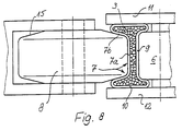
- Fig. 8
- eine Darstellung gemäß Fig. 3 aber mit einer Trockenmittel-Füllung.
- Fig. 1
- a bending device according to the invention with a pivotable and having a projection projecting into the inside of the bend and an abutment on the outside of the profile tool in the form of a pressure roller, the starting position, an intermediate position and the end position of the bend are Darge, on an enlarged scale
- Fig. 2
- a cross section of the profile to be bent in the starting position, it being between a support and a hold-down device on the one hand and between the abutment and the bending roller on the other hand,
- Fig. 3
- 2 a representation corresponding to FIG. 2 at the moment or especially in the final phase of the bending process,
- 4 and 5
- the mode of operation of the abutment, which is provided with a protrusion that increases increasingly in the pivoting direction, first in the starting position and then in the end position after bending, the pressure roller being omitted for the sake of clarity, wherein, as in FIG. 3, also clearly visible in FIG. 5, that the two inner and outer web walls come to lie against each other,
- Fig. 6
- a modified embodiment of a bending device according to the invention, in which the abutment performs in addition to its pivoting movement back and forth to the inner To deform profile wall into the profile and against the outer wall, as well
- Fig. 7
- a again modified embodiment, in which the abutment is arranged and remains only obliquely to the profile and is adjustable in its direction of extension deeper into the inner bend.
- Fig. 8
- a representation of FIG. 3 but with a desiccant filling.
Eine in allen Ausführungsbeispielen insgesamt mit 1 bezeichnete Vorrichtung dient zum Biegen eines Hohlprofiles 2, wobei vor allem in Fig.6 angedeutet ist, daß es sich dabei um die Herstellung eines mit Trockenmittel 3 gefüllten hohlen Abstandhalter-Rahmens für Isolierglasscheiben handeln kann. In einem solchen Falle würde das Profil 2 viermal gebogen werden können, falls der Rahmen aus einem einzigen Stück bestehen soll. An einer Längsseite könnten dann die beiden Profilenden stumpf aufeinanderstoßen und verbunden werden.A device designated overall by 1 in all exemplary embodiments serves for bending a
Etwa in Zuführrichtung des Profiles 2 ist an der Vorrichtung 1 eine Spannvorrichtung 4 zum Erfassen des vor der Biegung befindlichen Profilbereiches vorgesehen. Ferner hat die Vorrichtung 1 eine Einrichtung 5 zum Erfassen des umzubiegenden Schenkels sowie ein Widerlager 6 zum Fixieren der Innenseite der entstehenden Biegung oder Krümmung. Ferner ist in den Figuren 1, 6 u.7 angedeutet und in Fig.2, 3 u. 8 näher dargestellt, daß an der Außenseite der Biegestelle ein unter Anpreßdruck relativ zu dem Widerlager 6 bewegbares und an die Außenseite des Profiles anpreßbares Werkzeug, im Ausführungsbeispiel in Form einer wenigstens einen Teil des an der Ausseneite der Biegung befindlichen Profilsteges 7 beaufschlagende Druckwalze oder - rolle 8 vorgesehen ist, die in den Figuren 1, 6 u. 7 in unterschiedlichen Positionen dargestellt ist, um ihre Bewegung zu verdeutlichen. Der lichte Abstand des an der Außenseite der entstehenden Biegung des Profiles 2 angreifenden Werkzeuges 8 und des demgegenüber innenliegenden Widerlagers 6 ist, wie vor allem in den Figuren 3, 5 u.8 verdeutlicht, zumindest während des Biegevorganges wenigstens zeitweise kleiner als die Höhe der Seitenwände 10 des Profiles 2 und außerdem ist die quer zur Profil-Längserstreckung orientierte Abmessung A der wirksamen, d.h. mit den Stegen oder Wandungen 7 und 9 des Profiles in Berührung kommenden Fläche des Widerlagers 6 und die entsprechende Abmessung B des Werkzeuges 8 geringer als die Profilbreite und dabei auch geringer als der innere lichte Abstand der Seitenwände 10 des Profiles 2. Somit können die Wandungen und Steg 7 und 9 während des Biegens durch das Widerlager 6 und vor allem auch das Werkzeug 8 zwischen die Seitenwände 10 verformt werden bzw. kann vor allem das Werkzeug 8 zwischen die Seitenwände 10 eintauchen und den beim Biegen besonders beanspruchten, weil außenliegenden Steg 7 in einen Bereich eines kleineren Biegeradius bringen, wo entsprechend geringere Zugkräfte auftreten.Approximately in the feed direction of the
Um dabei unerwünschte und unkontrollierte Verformungen vor allem der Stege oder Wandungen 7 und 9 auszuschalten, die vor allem bei sehr dünnen Wandstärken bei einem Biegevorgang eines Hohlprofiles eine Gefahr darstellen und für einen auch im Biegebereich präzise bemessenen Abstandhalterrahmen vermieden werden müssen, sind die von Widerlager 6 und Werkzeug 8 beaufschlagten Stege 7 und 9 zumindest während des Biegens an ihren einander zugewandten Flächen mittelbar oder - wie im Ausführungsbeispiel nach Fig. 3 u. 5 dargestellt - unmittelbar gegeneineinander abgestützt. Dabei wird dies dadurch erreicht, daß der lichte Abstand des an der Außenseite der entstehenden Biegung des Profiles 2 angreifenden Werkzeuges 8 und des demgegenüber innenliegenden Widerlagers 6 zumindest während des Biegevorganges wenigstens zeitweise etwa gleich der Gesamtstärke der beiden von ihnen beaufschlagten und parallel zu ihnen und zueinander angeordneten Stegen oder Wandung 7 und 9 des Hohlprofiles 2 ist. In Fig. 5 ist dabei allerdings das Werkzeug 8 der besseren Übersicht wegen nicht dargestellt. Durch diese Maßnahme werden die beiden Stege 7 und 9 während des Biegens bestmöglich eingespannt und geführt, so daß sie auch bei sehr dünner Wandstärke keine unkontrollierten Verformungen, Verwerfungen oder Faltenbildungen erfahren können. Es liegt vielmehr durch Widerlager 6 und Werkzeug 8 genau fest, wie und wo diese Stege 7 und 9 im Biegebereich zu liegen kommen, so daß also schon vorher die optimale Lage dieser Stege vorbestimmt sein kann.
Dies gilt vor allem für ein trockenmittelfrei zu biegendes und erst später zu befüllendes Hohlprofil oder ein solches, bei welchem die Biegebereiche trockenmittelfrei gehalten oder gemacht werden, bevor die Biegung stattfindet. Gemäß Fig.8 kann aber auch bei einem ganz oder teilweise mit Trockenmittel gefüllten Profil die Abstützung der beiden Stege 7 u. 9 mittelbar dadurch geschehen, daß zwischen ihnen noch eine gegenüber der Gesamthöhe C des profiles in ihrer Dicke verminderte Trockenmittel-Zwischenlage vorhanden ist. Bevorzugt ist allerdings eine direkte Abstützung der beiden Stege 7 u. 9 gegeneinander, weil sie dann auch in die für ein Biegen günstigste Faser des Hohlprofiles verformt werden können.
In den Figuren 2 u. 3 ist verdeutlicht daß die quer zur Profil-Längserstreckung orientierte Abmessung A des Widerlagers 6 und die entsprechende Abmessung B des Werkzeuges 8 geringer als die Profilbreite und dabei sogar geringer als der innere lichte Abstand der Seitenwände 10 des Profiles 2 ist. Fig. 3 verdeutlicht sogar, daß die quer zur Profil-Längserstreckung orientierte Abmessung A des Widerlagers 6 und die entsprechende Abmessung B des Werkzeuges 8 sogar um mehr als zwei Wandstärken der Profilstege 10 geringer als der innere lichte Abstand der Seitenwände 10 des Profiles 2 ist. Somit kann in der in Fig. 3 u.8 dargestellten Weise die Druckrolle 8 unter Mitnahme eines Teiles der Außenwandung 7 zwischen die Seitenwände 10 in das Profil eintauchen und die Außenwand 7 gegen die Innenwand 9 hin verformen, die ihrerseits in noch zu beschreibender Weise nach innen verformt wird, so daß beide Wandungen 7 u.9 gem.Fig.2 und auch gem. Fig.5 aneinander zu liegen kommen und sich gegenseitig führen und stützen und vor allem an ungewollten und unkontrollierten Verwerfungen und Faltungen hindern. Fig. 5 verdeutlicht dabei, wie die beiden Wandungen 7 u.9 allmählich einander angenähert werden, bis sie sich im Biegebereich selbst tatsächlich berühren. Die schmalere Biegerolle 8 und die noch zu beschreibenden Niederhalter 11 u.12, deren letzterer eine Auflage sein kann, bewirken dabei die gezielte und präzise Verformung der einzelnen Stege 7 u.9, so daß diese innerhalb der Biegung teilweise nahezu parallel zu den Außenwänden 10 verlaufen. Dies erlaubt nicht nur die gewünschte enge Biegung, sondern führt auch zu einer entsprechend steifen und stabilen Formgebung in dem Biegebereich trotz der vorhergehenden Verformungen. Somit können auch sehr dünnwandige Hohlprofile mit engen Biegungen mit möglichst geringem Krümmungsradius an der Innenseite mit der erfindungsgemäßen Vorrichtung 1 hergestellt werden.In order to eliminate undesired and uncontrolled deformations, above all of the webs or
This applies above all to a hollow profile that is to be bent without desiccant and only to be filled later, or one in which the bending areas are kept or made desiccant-free before the bending takes place. According to Figure 8, the support of the two webs 7 u. 9 happen indirectly by the fact that between them there is a drying agent intermediate layer which is reduced in thickness compared to the total height C of the profile. However, direct support of the two webs 7 u is preferred. 9 against each other because they can then also be deformed into the fiber of the hollow profile that is most favorable for bending.
In Figures 2 u. 3 shows that the cross Dimension A of the
Für die gezielte Verformung eines Teiles der Außenwandung 7 nach innen ist die Druckrolle 8 nahe ihrem als Arbeitsfläche 13 wirkenden Umfang an ihren Seitenflächen 14 umlaufend abgeschrägt. Diese Schrägung ist in Fig.2 mit 15 bezeichnet. Vor allem Fig. 3 verdeutlich dabei, daß die größere Breite der Druckrolle 8 gleich oder kleiner dem inneren lichten Abstand der Seitenwände 10 des Profiles 2 ist und daß der schmalere Bereich 13 der Druckrolle 8 in seiner Breite etwa der Breite eines an dem Profil 2 außenliegenden Stegbereiches 7a entspricht, von welchem jeweils schräge Stegbereiche 7b zu den Seitenwänden 10 hin abfallen (vgl. vor allem Fig.2).For the targeted deformation of a part of the
Die Abschrägungen 15 an den Seitenflächen 14 der Biege- oder Druckrolle 8 haben dabei eine radiale Breite, die gleich oder - im Ausführungsbeispiel - größer als die Eintauchtiefe der Biegerolle 8 beim Biegen und Eindrücken des Außensteges 7 in Richtung zu dem Widerlager 6 hin hat. In Fig. 3 erkennt man, daß noch ein Stück der Abschrägung 15 nach dem Eindrücken der Rolle 8 in das Profil 2 aus diesem vorsteht.The
Wichtig für einen schnellen und problemlosen Verlauf der Verformung beim Biegen ist das schon mehrfach erwähnte Widerlager 6. Dieses ist ein in den verschiedenen Ausführungsbeispielen jeweils etwas abgewandelt gestaltetes Formstück, dessen Außenkontur der Innenkontur der herzustellenden Innenbiegung entspricht, wie es beispielsweise in Fig. 5 verdeutlicht ist. Das Widerlager 6 steht dabei wenigstens zeitweise während des Biegels gegenüber den beiden nach dem Biegen im Winkel zueinanderstehenden Innenseiten oder Stegen der Rahmenschenkel in Richtung zu der Außenseite der Biegung und des Profiles vor, so daß also die Innenseite der Biegung eine Einbuchtung erhält, wie es in Fig.1 und vor allem in Fig.5, aber auch in Fig. 3 verdeutlich ist. Dadurch wird nämlich auch der an der Innenseite der Biegung liegende Steg 9 etwas nach innen verformt und eingedrückt und dem von außenher eingedrückten Steg 7 bis zur Berührung mit diesem angenähert. Diese Maßnahme dient also ebenfalls dazu, die beiden am stärksten während des Biegens belasteten Wandungen oder Stege 7 u.9 unmittelbar gegeneinander zu führen und so an unkontrollierten Verformungen zu hindern.The
Gegebenenfalls kann das Widerlager 6 oder das als Widerlager dienende Formstück zur Anpassung an unterschiedliche Profile, Stegdicken, Stegformen od.dgl. auswechselbar sein. Somit kann die Biegevorrichtung 1 vor allem auch für Profile unterschiedlicher Abmessungen eingesetzt werden. Gegebenenfalls ist es dabei auch zweckmäßig, die Druckrolle 8 auswechselbar zu gestalten.If necessary, the
Um eine allmähliche Verformung auch an der Innenseite der Biegung zu erzielen ist es zweckmäßig, wenn das Widerlager 6 in noch zu beschreibender Weise während des Biegevorganges - ggf. gesteuert - tiefer und tiefer in die Biegung hineinbewegbar oder verschiebbar ist. Somit wird zu Beginn eines Biegevorganges natürlich noch nicht erreicht sein, daß sich Innenwandung 9 und Außenwandung 7 des Profiles tatsächlich berühren. Nach einer gewissen Biegezeit ist dies jedoch dann erreicht und zwar so frühzeitig, daß vor allem die immer mehr zunehmende Biegung dann bei aneinanderliegenden Wandungen 7 u.9 ablaufen kann. In den Fig.1, 6 u.7 erkennt man dabei deutlich, daß das schwenk- und/oder verschiebbare Widerlager 6 in Vorschubrichtung unmittelbar benachbart hinter der Spannvorrichtung 4 zum Erfassen des vor der Biegung befindlichen Profilbereiches angeordnet ist. Es ist also gegenüber dieser Spannvorrichtung 4 getrennt, kann also unabhängig von dieser Bewegungen zur Optimierung des Biegevorganges durchführen.In order to achieve a gradual deformation also on the inside of the bend, it is expedient if the
Bei den Ausführungbeispielen gemäß Fig.1 u.6 hat das Widerlager 6 an seinem während des Biegens an der Innenseite der entstehenden Biegung anliegenden Druckbereich eine Fortsetzung 16 als Anschlag für den umzubiegenden Schenkel hinter der Biegung. In diesem Falle ist das Widerlager 6 mit seiner als Anschlag dienenden Fortsetzung 16 beim Biegevorgang mit einem den umzubiegenden Rahmenschenkel an der Außenseite beaufschlagenden Biegeanschlag 17 zusammen verschwenkbar, wobei das Profil zwischen der Widerlager-Fortsetzung 16 und diesem Biegeanschlag 17 eingespannt ist, so daß diese Teile praktisch die Einrichtung 5 zum Erfassen des umzubiegenden Schenkels bilden. Lediglich bei der noch näher zu erläuternden Ausführungsform gem. Fig. 7 sind diese Einrichtung 5 und das Widerlager 6 mit seiner Fortsetzung unabhängig voneinander.In the exemplary embodiments according to FIGS. 1 and 6, the
Es wurde bereits erwähnt, daß des Widerlager 6 allmählich in das Innere des Profiles 2 eintaucht. Besonders vorteilhaft ist es, wenn es während des Biegens etwa bis in den Bereich der neutralen Faser des zu biegenden Profiles 2 ragt oder bewegbar oder verschiebbar ist. Dabei zeigen die Figuren 1,4 u.5 ein besonders zweckmäßiges Ausführungsbeispiel, bei welchem das Widerlager 6 einen gegenüber seiner Fortsetzung 16 seitlich und insbesondere exzentrisch vorstehenden Vorsprung 6a zum Eindrücken in die entstehende Innenseite der Biegung hat, dessen Abmessung in Richtung seiner Verschwenkung in dem Sinne zunimmt, daß durch die Verschwenkung der Fortsetzung 16 und des Widerlagers 6 gemäß dem Pfeil Pf 1 in Fig.4 der Vorsprung 6a zunehmend tiefer in die Innenseite der Biegung eintritt, wie man es deutlich beim Vergleich der Figuren 4 u.5 erkennt. Dabei sind in den Figuren 4 u.5 Maßlinien L im Bereich des Vorsprunges 6a ausgehend von einem zentralen Punkt M jeweils zur Peripherie des Vorsprunges 6a dargestellt, um durch deren entgegen dem Pfeil Pf 1 immer größer werdende Länge die Exzentrizität des Vorsprunges 6a und das dadurch bewirkte allmählich stärkere Eindringen des Widerlagers 6 in das Profil 2 zu verdeutlichen. Der Pfeil Pf 1 ist dabei auch in Fig. 1 eingezeichnet. Ferner erkennt man so, daß die Außenseite des Vorsprunges 6a mitgeschwenkt wird und die Wandung 9 gewissermaßen mitzieht. Abgewandelte Lösungen bezüglich des allmählichen tieferen Eintretens des Widerlagers 6 in die Innenseite der Biegung zeigen die Figuren 6 u.7, wobei in beiden Fällen das Widerlager und eine an ihm befindliche Fortsetzung 16 in einem spitzen Winkel zu dem ankommenden noch nicht gebogenen Profil 2 angeordnet und in dieser Orientierungsrichtung gemäß den Pfeilen Pf 2 bzw. Pf 3 verschiebbar gelagert sind. Somit kann gemäß der strichpunktierten Darstellung des Widerlagers 6 und seiner Fortsetzung 16 wiederum der Bereich der Innenseite der entstehenden Biegung nach innen eingebuchtet werden, wobei in diesem Falle das das Widerlager 6 bildende Formstück praktisch eine bogen- oder kreisbogenförmige Aussenkontur hat.It has already been mentioned that the
Bei der Lösung nach Fig.6 ist vorgesehen, daß der Verschwenkbewegung des verschwenkbaren Widerlagers 6 mit seiner Fortsetzung 16, welches mit seiner Oberfläche während der Verschwenkung an der Innenseite der Biegung im Sinne des Profilvorschubes wirkend angreift, wenigstens eine in Orientierungsrichtung der Fortsetzung 16 gerichtete Verschiebebewegung gemäß dem Doppelpfeil Pf 2, im Ausführungsbeispiel eine solche Verschiebebewegung kurz nach dem Beginn der Biegung und eine weitere derartige Verschiebebewegung kurz vor Vollendung der Biegung, überlagert ist. Dabei ist dies im Ausführungsbeispiel nach Fig. 6 dadurch realisiert, daß das Widerlager 6 und seine Fortsetzung 16 einen in eine Steuerkurve 18 eingreifenden Vorsprung 19 hat, wobei die Steuerkurve 18 im wesentlichen entsprechend der Verschwenkung dieses Vorsprunges 19 beim Verschwenken des Widerlagers 6 orientiert ist und Auslenkungen 18a für die überlagerten Verschiebebewegungen hat. In diesem Falle wird also eine ganz präzise gesteuerte Bewegung des Widerlagers 6 mit Hilfe dieser Steuerkurve 18 und des Vorsprunges 19 bewirkt, wobei diese Steuerung mechanisch erfolgt. Selbstverständlich ist aber auch eine andereKupplung der Schwenkbewegung einerseits mit einer solchen Verschiebebewegung des Widerlagers 6 andererseits möglich und bei der Ausführungsform nach Fig.7 auch nötig, weil dort das Widerlager 6 mit seiner Fortsetzung 16 in seiner schräg zum ankommenden Profil liegenden Position bleibt und in dieser Position gemäß dem Pfeil Pf 3 verstellbar ist, während die Einrichtung 5 den zu verbiegenden Schenkel des Profiles 2 aus der Ausgangslage mehr und mehr verbiegt, wie es strichpunktiert in Fig. 7 dargestellt ist.In the solution according to FIG. 6, it is provided that the pivoting movement of the
Es wurde bereits erwähnt, daß Niederhalter 11 bzw. eine Auflage 12 und ein Niederhalter 11 für die Seitenwände 10 des Profiles 2 im Biegerbereich vorgesehen sind, deren Abstand auf die Breite des Profiles 2 und den späteren lichten Abstand zweier Glasscheiben einstellbar ist. Somit werden während des Biegevorganges Ausweichbewegungen der Seitenwände 10 vermieden, wie es vor allem durch Fig. 3 verdeutlicht ist. Dabei ist wenigstens einer dieser beidseits des Profiles 2 an dessen Seitenwänden 10 angreifenden Niederhalter 11 zustellbar und wieder aus dem Bereich des Profiles 2 wegbewegbar, was nicht nur das Einlegen und Entnehmen des Profiles 2 oder des gebogenen Rahmens erleichtert, sondern auch die Anpassung an unterschiedliche Profilbreiten erleichtert.It has already been mentioned that hold-down
Dabei kann in nicht näher dargestellter Weise im Bereich des Biegewerkzeuges 8 ein von dem Widerlager 6 gegen die Innenseite der Biegung gerichteter Auswerfer od.dgl. vorgesehen sein, der nach dem Biegen das Entnehmen des verformten profiles erleichtert. Gegebenenfalls könnte sogar das Widerlager 6 vor allem bei der Lösung nach Fig.7 durch eine weitere Verschiebung in Richtung des Pfeiles Pf 3 als Auswerfer dienen.In this case, an ejector or the like directed by the
Es wurde schon erwähnt, daß die Vorrichtung 1 beispielsweise dazu eingesetzt werden kann, mit Trockenmittel gefüllte hohle Abstandhalter-Profile zu Abstandhalter-Rahmen für Isolierglasscheiben zu biegen. Dabei ist es dann jedoch wichtig und zweckmäßig, um die Profilwandungen 7 u.9 während des Biegevorganges wenigstens zeitweise aneinanderdrücken zu können, wenn das Innere des Profiles 2 im Biegerbereich während des Biegevorganges ganz oder wenigstens teilweise frei von dem Trockenmittel 3 ist. Dies läßt sich natürlich auf verschiedene Weisen bewirken. Im Ausführungsbeispiel gem. Fig.6 ist eine Lösung für einen solchen Fall dargestellt, bei welchem das Hohlprofil 2 auf der Innenseite der entstehenden Biegung perforiert ist, damit das Trockenmittel später auch gegen den Scheibenzwischenraum hin wirksam wird. Man erkennt in Fig.6 im Bereich der Innenseite der Biegung an der Biegevorrich-tung 1 eine Einrichtung zum wenigstens zeitweiligen Verdrängen oder Beseitigen von Trockenmittel 3 aus dem zu biegenden Bereich in Form einer gegen die Perforierung des Profiles 2 gerichteten Druckluftdüse 20. Dabei ist diese zum Verdrängen von Trockenmittel 3 aus dem Biegebereich dienende Druckluftdüse 20 nahe dem Widerlager 6 und der innenseitig angeordneten Spannvorrichtung 4 angeordnet. In diesem Falle durchsetzt sie sogar diese Spannvorrichtung 4 und mündet unmittelbar vor dem Biegebereich und vor dem Widerlager 6, so daß die Luft den Biegebereich freiblasen kann.It has already been mentioned that the
Die Luftdüse 20 ist in der Ausführungsform nach Fig.6 schräg gegen die Innenseite des vor der Biegung befindlichen Bereiches des Profiles 2 gerichtet und schließt mit dem vor der Biegung verbleibenden Schenkel und der Vorschubrichtung des Profiles 2 beim Einführen in die Biegevorrichtung 1 einen spitzen Winkel ein. Somit wird ein größer Teil des Trockenmittels 3 in Erstreckungsrichtung des Profiles 2 vorwärtsgeblasen werden, während aber auch ein Teil durch den entstehenden Überdruck zurückgeblasen wird. In Fig. 6 ist deutlich erkennbar, daß der Biegebereich selbst von dem Trockenmittel frei ist, während dieses sich beidseits dieses Trockenmittelfreien Bereiches etwas aufgestaut hat, weil es von der Druckluft verdrängt wurde. Somit kann insbesondere unter fortgesetzter Einblasung von Luft die Biegung durchgeführt werden ohne daß das Trockenmittel 3 dies behindert, so daß auch die Wandungen 7 u.9 sich gemäß Fig.3 trotz des Trockenmittels 3 berühren können.In the embodiment according to FIG. 6, the
Dabei könnte sogar im Biegebereich etwas Trockenmittel verbleiben oder wieder hingelangen, da gemäß Fig. 3 zwischen den nach innen verformten Stegbereichen 7b und den Seitenwandungen 10 ein Zwischenraum verbleibt oder verbleiben kann.
Eine andere Möglichkeit besteht darin, zunächst ein leeres Profil 2 zu biegen und dann Trockenmittel nachträglich einzufüllen, insbesondere bevor das Profil endgültig geschlossen wird, gegegenenfalls auch bevor die letzte Biegung durchgeführt wird, wobei es nicht unbedingt erforderlich ist, daß alle Schenkel des Rahmens anschließend vollständig mit Trockemittel gefüllt sind.In this case, some desiccant could even remain in the bending area or get back there, since, according to FIG. 3, a space remains or can remain between the inwardly deformed web areas 7b and the
Another possibility is to first bend an
Es sie noch erwähnt, daß die Biegerolle 8 zur Anpassung an unterschiedliche und vor allem unterschiedlich breite Profile 2 austauschbar sein kann.It also mentions that the bending
Claims (23)
- An apparatus (1) for bending a hollow profile (2) - preferbly for making a hollow spacer frame, particularly a spacer frame filled with drying agent(3), for insulating glass panes - including a clamping device (4) which is located approximately in the direction of feed of the profile (2) and serves for taking hold of the profile area situated in front of the bend, including a device (5) for taking hold of the limb to be bent over, as well as an abutment (6) for fixing the inside of the bend or curvature being formed, and further including at the outside of the bend location a tool (8) which is movable under contact pressure relative to the abutment (6) and the profile (2) and is adapted to be pressed against the outside of the profile, the tool particularly being in the form of a press roller, press roll (8) or the like acting on at least part of the web (7) situated at the outside of the bend, at least during the bending operation the clearance between the tool (8) acting on the outside of the bend being formed in the profile (2) and the opposed abutment (6) lying within being smaller, at least for a time, than the height of the side walls (10) of the profile (2), characterized in that at least during the bending operation and at least for a time, the clearance between tool (8) and abutment (6) is at least equal to the total thickness of the two webs or walls (7,9) of the hollow profile (2) which are acted upon by and are arranged parallel to tool and abutment and are parallel to each other, or is equal to the total thickness of the two webs (7,9) plus an intermediate layer of drying agent preferably reduced in its extent relative to the total thickness of the profile, and that that dimension (A) of the active face of the abutment (6) and of the tool (8) which is oriented transversely to the longitudinal expanse of the profile is at least two wall thicknesses of the profile webs (10) smaller than the inner clearance of the side walls (10) of the profile (2) in such a way that the abutment (6) and the tool (8) enter between the side walls (10) of the profile, indenting the outer webs (7, 9) they act upon.
- An apparatus as claimed in claim 1, characterized in that during the bending the webs (7, 9) acted upon by abutment (6) and tool (8) are supported flat indirectly or directly against each other at their confronting surfaces.
- An apparatus as claimed in claim 1 or claim 2, characterized in that near the tool circumference acting as the working surface (13) the press roll (8) has a circumferential taper (15) at its side faces (14) and that the greater width of the press roll (8) is greater than, equal to or smaller than the inner clearance of the side walls (10) of the profile (2) and that the narrower area (13) of the press roll (8) corresponds in its width approximately to the width of a web area (7a) which is situated externally on the profile (2) and from which web areas (7b) slant towards the side walls (10).
- An apparatus as claimed in claim 3, characterized in that the tapers (15) at the side faces (14) of the bending roll or press roll (8) have a radial width which is equal to or greater than the depth to which the bending roll (8) enters in bending and indenting the outer web (7) in a direction towards the abutment (6).
- An apparatus as claimed in any one of claims 1 to 4, characterized in that the abutment (6) situated at the inside of the bend is a shaped part, the outer contour thereof corresponding to the inner contour of the inside bend to be made, in relation to the two inner surfaces or webs of the frame piece which after being bent are at an angle to each other the abutment projecting - at least for a time during the bending - in a direction towards the outside of the bend and of the profile, so as to impart an indentation to the inside of the bend.
- An apparatus as claimed in any one of claims 1 to 5, characterized in that the abutment (6) or the shaped part serving as the abutment is exchangeable for adaptation to different profiles, web thicknesses, web shapes or the like.
- An apparatus as claimed in any one of claims 1 to 6, characterized in that during the bending operation the abutment (6) is movable or shiftable, particularly controlled, to proceed deeper into the bend.
- An apparatus as claimed in any one of claims 1 to 7, characterized in that the swingable and/or shiftable abutment (6) is arranged such that in the direction of feed it is directly adjacent to the clamping device (4) for taking hold of the profile area situated in front of the bend.
- An apparatus as claimed in any one of claims 1 to 8, characterized in that the abutment (6) has at its pressure area lying, during bending, against the inside of the bend being formed a continuation (16) as a stop for the limb to be bent over.
- An apparatus as claimed in any one of claims 1 to 9, characterized in that during the bending operation, the abutment (6) along with its continuation (16) serving as a stop is swingable together with a bending stop (17) acting on the outside of the of the limb to be bent over, the profile preferably being restrained between the abutment continuation (16) and said bending stop (17).
- An apparatus as claimed in any one of claims 1 to 10, characterized in that during bending, the abutment (6) projects or is movable or shiftable approximately into the area of the neutral axis of the profile (2) to be bent.
- An apparatus as claimed in any one of claims 1 to 11, characterized in that the abutment (6) has projecting preferably laterally relative to its continuation (16), particularly eccentrically, a protuberance (6a) for pressing into the inside being formed in the bend, the size of the protuberance increasing in the direction in which the abutment swings, to the effect that through the swing movement of the continuation (16) and abutment (6) the protuberance (6a) enters the inside of the bend to increasing depth.
- An apparatus as claimed in any one of claims 1 to 12, characterized in that the abutment (6) and a continuation (16) on it are arranged at an acute angle to the incoming profile (2) still in the unbent state and are shiftably supported in the direction of orientation thereof.
- An apparatus as claimed in any one of claims 1 to 13, characterized in that the swing movement performed by the swingable abutment (6), during which the abutment has its surface acting on the inside of the bend in the direction of feed of the profile, is superimposed by at least one shifting movement in the direction in which the continuation (16) of the abutment is oriented, preferably by one such shifting movement shortly after commencement and a further one shortly before completion of the bend.
- An apparatus as claimed in claim 14, characterized in that the abutment (6) and/or continuation (16) thereof has a projection (19) or the like engaging a cam (18), the cam (18) being oriented essentially in correspondence with the swing movement of said projection (19) as the abutment (6) swings and having deflectors (18a) for the superimposed shifting movements.
- An apparatus as claimed in any one of claims 1 to 15, characterized in that hold-down devices (11) or a support (12) and a hold-down device (11) or like guides for the side walls (10) of the profile (2) are provided in the bend area, the spacing of the hold-down devices being adjustable to the width of the profile (2) and the later clearance of two panes of glass.
- An apparatus as claimed in claim 16, characterized in that at least one of the hold-down devices (11) or the like acting on the side walls (10) at either side of the profile (2) is adapted to be infed and moved away again from the area of the profile (2).
- An apparatus as claimed in any one of claims 1 to 17, characterized in that an ejector or the like directed from the abutment (6) towards the inside of the bend is provided in the area of the bending tool (8).
- An apparatus for bending a hollow spacekeeping profile filled with drying agent for insulating glass panes, as claimed in any one of claims 1 to 18, characterized in that in the bend area the interior of the profile (2) is wholly or at least partly free from drying agent (3) during the bending operation.
- An apparatus for bending a hollow profile which is filled with drying agent and is perforated on the inside of the bend being formed, as claimed in claim 19, characterized in that the bending apparatus (1) has in the area of the inside of the bend a device for at least temporarily displacing or removing drying agent (3) from the profile area to be bent, particularly a compressed-air nozzle (20) directed towards the perforation of the profile (2).
- An apparatus as claimed in claim 20, characterized in that the compressed-air nozzle (20) serving to displace drying agent (3) from the bend area is arranged near the abutment (6) and/or the clamping device (4) arranged at the inside, said compressed-air nozzle preferably traversing said clamping device (4) and ending directly in front of the bend area of the profile.
- An apparatus as claimed in claim 20 or claim 21 characterized in that the air nozzle (20) is directed slantwise towards the inside of that area of the profile (2) which is situated in front of the bend and said air nozzle forms an acute angle with the limb remaining in front of the bend and with the direction in which the profile (2) is fed when being introduced into the bending apparatus (1).
- An apparatus as claimed in any one of the preceding claims, characterized in that the bending roll (8) is exchangeable for adaptation to different profiles and particularly ones (2) of different width.
Priority Applications (1)
| Application Number | Priority Date | Filing Date | Title |
|---|---|---|---|
| AT88118909T ATE80071T1 (en) | 1987-12-03 | 1988-11-12 | DEVICE FOR BENDING A HOLLOW PROFILE, IN PARTICULAR A SPACER FRAME FOR INSULATING GLASS PANES. |
Applications Claiming Priority (2)
| Application Number | Priority Date | Filing Date | Title |
|---|---|---|---|
| DE3740921 | 1987-12-03 | ||
| DE19873740921 DE3740921A1 (en) | 1987-12-03 | 1987-12-03 | DEVICE FOR PRODUCING A BEND ON A HOLLOW RECTANGLE PROFILE |
Publications (4)
| Publication Number | Publication Date |
|---|---|
| EP0318748A2 EP0318748A2 (en) | 1989-06-07 |
| EP0318748A3 EP0318748A3 (en) | 1990-06-13 |
| EP0318748B1 EP0318748B1 (en) | 1992-09-02 |
| EP0318748B2 true EP0318748B2 (en) | 1997-12-17 |
Family
ID=6341773
Family Applications (1)
| Application Number | Title | Priority Date | Filing Date |
|---|---|---|---|
| EP88118909A Expired - Lifetime EP0318748B2 (en) | 1987-12-03 | 1988-11-12 | Apparatus for bending a hollow profile, in particular a frame of spacekeeping profiles for insulating glass panes |
Country Status (5)
| Country | Link |
|---|---|
| US (1) | US4945619A (en) |
| EP (1) | EP0318748B2 (en) |
| AT (1) | ATE80071T1 (en) |
| DE (2) | DE3740921A1 (en) |
| ES (1) | ES2035221T5 (en) |
Cited By (4)
| Publication number | Priority date | Publication date | Assignee | Title |
|---|---|---|---|---|
| DE19733536A1 (en) * | 1997-08-02 | 1999-02-18 | Bayer Isolierglasfab Kg | Device for bending a hollow profile with a hold-down device |
| DE19839444C1 (en) * | 1998-08-29 | 2000-01-05 | Bayer Isolierglasfab Kg | Bending metal-coated plastic hollow profile containing drying agent, forming double-glazing spacer frame |
| DE19956046B4 (en) * | 1999-11-22 | 2004-12-30 | Bayer Isolierglas- Und Maschinentechnik Gmbh | Method and device for producing a spacer frame for insulating glass panes |
| DE19839735B4 (en) * | 1998-09-01 | 2005-03-03 | Franz Xaver Bayer Isolierglasfabrik Kg | Device for bending a spacer-holding inner frame for an insulating glass pane |
Families Citing this family (28)
| Publication number | Priority date | Publication date | Assignee | Title |
|---|---|---|---|---|
| DE3829290A1 (en) * | 1988-08-30 | 1990-03-15 | Bayer Ag | POLYETHEROL POLYOLS BASED ON AROMATIC DI AND / OR POLYAMINES, PROCESS FOR THEIR PREPARATION AND USE OF POLYURETHANE AND POLYISOCYANURATE PLASTICS |
| DE3942809A1 (en) * | 1989-12-23 | 1991-06-27 | Bayer Isolierglasfab Kg | METHOD AND DEVICE FOR PRODUCING A SPACER FRAME, IN PARTICULAR FOR INSULATING GLASS PANELS |
| DE3942808A1 (en) * | 1989-12-23 | 1991-06-27 | Bayer Isolierglasfab Kg | METHOD AND DEVICE FOR PRODUCING A SPACER FRAME |
| DE4104997A1 (en) * | 1990-02-21 | 1991-08-29 | Bernhard Kreye | Bending hollow metal frame extrusion - by fitting male tool inside, placing in slotted female tools which partly surround it, and bending in machine using polyamide for all tools |
| US5243844A (en) * | 1990-05-21 | 1993-09-14 | Peter Lisec | Process for producing curved sections in hollow profile strips |
| AT397054B (en) * | 1990-05-21 | 1994-01-25 | Lisec Peter | DEVICE FOR BENDING HOLLOW PROFILE STRIPS |
| ES2051109T3 (en) * | 1990-05-21 | 1994-06-01 | Peter Lisec | DEVICE FOR FOLDING HOLLOW MOLDINGS. |
| AT405912B (en) * | 1990-10-02 | 1999-12-27 | Lisec Peter | Method and apparatus for bending hollow sectional strips |
| DK0459971T3 (en) * | 1990-05-21 | 1994-04-05 | Peter Lisec | Method and apparatus for generating bent sections in hollow profile moldings |
| AT397055B (en) * | 1990-06-07 | 1994-01-25 | Lisec Peter | METHOD AND DEVICE FOR BENDING HOLLOW PROFILE BARS TO SPACER FRAME FOR INSULATING GLASS PANELS |
| DE59100838D1 (en) * | 1990-06-07 | 1994-02-24 | Peter Lisec | Method and device for bending hollow profile strips to form spacer frames for insulating glass panes. |
| DK169909B1 (en) * | 1990-10-26 | 1995-04-03 | Bayer Isolierglasfab Kg | Bending machine |
| DK9192A (en) * | 1992-01-24 | 1993-07-25 | Skovgaard & Co As | PROCEDURE AND APPARATUS FOR BENDING THE THICK WALL, HOLE DISTANCE PROFILE |
| DE4225833C2 (en) * | 1992-08-05 | 1994-07-28 | Bayer Isolierglasfab Kg | Bending device for hollow profiles |
| IT1266114B1 (en) * | 1993-08-02 | 1996-12-20 | For El Base Di Vianello Fortun | DEVICE FOR FILLING SPACER FRAMES FOR CHAMBER-GLASS WITH HYGROSCOPIC MATERIAL |
| FR2774625B1 (en) | 1998-02-10 | 2000-03-10 | Seva | PROCESS FOR FOLDING PROFILES COMPRISING A HOLLOW BODY AND A COATING SHEET, AND PROFILE FOLDED THEREBY |
| FR2774624B1 (en) * | 1998-02-10 | 2000-03-10 | Seva | PROCESS FOR FOLDING PROFILES COMPRISING A HOLLOW BODY AND A COATING SHEET, AND PROFILE FOLDED THEREBY |
| US6601291B2 (en) * | 2001-06-14 | 2003-08-05 | Georgia-Pacific Resins, Inc. | Apparatus and method of producing a core board product |
| DE10138345B4 (en) * | 2001-08-03 | 2008-12-04 | Lenhardt Maschinenbau Gmbh | Device for bending hollow profiled bars |
| DE10137766A1 (en) * | 2001-08-03 | 2003-02-27 | Lenhardt Maschinenbau | Device for bending hollow profile bars |
| US6619098B2 (en) | 2001-08-28 | 2003-09-16 | Peter Lisec | Process and device for bending of hollow profile strips into spacer frames for insulating glass panes |
| DE10236373B4 (en) * | 2002-08-02 | 2007-10-11 | Takata Corp. | Method for bending a filling tube for an airbag module and device for carrying out this method |
| DE102004060805A1 (en) * | 2004-11-05 | 2006-05-11 | Lenhardt Maschinenbau Gmbh | Hollow section bar e.g. spacer frame, bending device for insulating glass plate, has bending tool with rolls rotated parallel to each other, where shell of one roll has projecting section in center of its section facing outer wall of bar |
| EP2288777A2 (en) * | 2008-04-11 | 2011-03-02 | Plus Inventia AG | Method for producing a corner of a frame-type spacer for insulating glass panels and spacer and insulating glass panels produced according to said method |
| JP5233682B2 (en) * | 2009-01-08 | 2013-07-10 | アイシン・エィ・ダブリュ株式会社 | Bending machine |
| CN102248041A (en) * | 2010-05-17 | 2011-11-23 | 赵士平 | Locating device in hollow glass aluminium division bar bender |
| US10183363B2 (en) | 2015-08-04 | 2019-01-22 | Cardinal Ig Company | Spacer formation cell |
| CA3012935C (en) * | 2017-03-10 | 2020-03-24 | Allmetal, Inc. | Insulating glass spacer construction |
Family Cites Families (8)
| Publication number | Priority date | Publication date | Assignee | Title |
|---|---|---|---|---|
| GB624169A (en) * | 1944-11-21 | 1949-05-30 | Sncase | Improvements in machines for bending angle and other metal rods, bars or the like |
| US3553990A (en) * | 1968-04-23 | 1971-01-12 | Pines Engineering Co Inc | Tube bender pressure die interference control |
| CA1134125A (en) * | 1978-06-14 | 1982-10-26 | Theo Janssens | Hollow panels and method of and apparatus for manufacturing same |
| CH660398A5 (en) * | 1982-01-21 | 1987-04-15 | Peter Lisec | SPACER FRAME FOR INSULATING GLASS PANELS AND METHOD FOR PRODUCING THE SAME AND DEVICE FOR IMPLEMENTING THE METHOD. |
| CA1246978A (en) * | 1983-04-09 | 1988-12-20 | Franz Bayer | Method of and apparatus for making spacers for use in multiple-pane windows of the like |
| DE3312764A1 (en) * | 1983-04-09 | 1984-10-18 | Fr. Xaver Bayer Isolierglasfabrik Kg, 7807 Elzach | METHOD AND DEVICE FOR BENDING SPACER PROFILES FOR INSULATING GLASS PANELS |
| DE3346671C1 (en) * | 1983-12-23 | 1985-07-04 | Karl 7531 Neuhausen Lenhardt | Process for forming the corners of spacer frames for edge-glued insulating glass panes |
| DE3740922A1 (en) * | 1987-12-03 | 1989-06-22 | Bayer Isolierglasfab Kg | METHOD AND DEVICE FOR PRODUCING A SPACER FRAME |
-
1987
- 1987-12-03 DE DE19873740921 patent/DE3740921A1/en active Granted
-
1988
- 1988-11-12 DE DE8888118909T patent/DE3874298D1/en not_active Expired - Lifetime
- 1988-11-12 EP EP88118909A patent/EP0318748B2/en not_active Expired - Lifetime
- 1988-11-12 ES ES88118909T patent/ES2035221T5/en not_active Expired - Lifetime
- 1988-11-12 AT AT88118909T patent/ATE80071T1/en not_active IP Right Cessation
- 1988-12-05 US US07/280,090 patent/US4945619A/en not_active Expired - Lifetime
Cited By (5)
| Publication number | Priority date | Publication date | Assignee | Title |
|---|---|---|---|---|
| DE19733536A1 (en) * | 1997-08-02 | 1999-02-18 | Bayer Isolierglasfab Kg | Device for bending a hollow profile with a hold-down device |
| DE19733536C2 (en) * | 1997-08-02 | 2001-10-11 | Bayer Isolierglasfab Kg | Bending device with a hold-down device for hollow profiles |
| DE19839444C1 (en) * | 1998-08-29 | 2000-01-05 | Bayer Isolierglasfab Kg | Bending metal-coated plastic hollow profile containing drying agent, forming double-glazing spacer frame |
| DE19839735B4 (en) * | 1998-09-01 | 2005-03-03 | Franz Xaver Bayer Isolierglasfabrik Kg | Device for bending a spacer-holding inner frame for an insulating glass pane |
| DE19956046B4 (en) * | 1999-11-22 | 2004-12-30 | Bayer Isolierglas- Und Maschinentechnik Gmbh | Method and device for producing a spacer frame for insulating glass panes |
Also Published As
| Publication number | Publication date |
|---|---|
| DE3740921C2 (en) | 1989-09-21 |
| EP0318748A3 (en) | 1990-06-13 |
| ES2035221T3 (en) | 1993-04-16 |
| ES2035221T5 (en) | 1998-04-16 |
| EP0318748A2 (en) | 1989-06-07 |
| DE3740921A1 (en) | 1989-06-15 |
| DE3874298D1 (en) | 1992-10-08 |
| ATE80071T1 (en) | 1992-09-15 |
| US4945619A (en) | 1990-08-07 |
| EP0318748B1 (en) | 1992-09-02 |
Similar Documents
| Publication | Publication Date | Title |
|---|---|---|
| EP0318748B2 (en) | Apparatus for bending a hollow profile, in particular a frame of spacekeeping profiles for insulating glass panes | |
| EP2529849B1 (en) | Device and method for manufacturing slot pipes made of sheet panels | |
| EP1796859B1 (en) | Method and device for production of a longitudinal seam welded hollow profile | |
| EP0318749B1 (en) | Process and device to produce spacer frames | |
| EP1954420B1 (en) | Method and device for the coreless forming of hollow profiles | |
| DE19717472A1 (en) | Method and device for profile bending with modular bending stations | |
| EP1089835A1 (en) | Method and device for producing straight bead welded pipes from flat sheet metal blanks | |
| EP1781430B1 (en) | Method and device for the production of a longitudinally welded hollow profile | |
| WO2009023973A1 (en) | Apparatus and process for shaping a tube from a metal sheet | |
| DE2642743B2 (en) | Device for manufacturing a motor vehicle axle | |
| DE102018211311B4 (en) | Extended regulation of JCO molding press | |
| EP0894553B1 (en) | Apparatus for bending a hollow profile with a clamp | |
| DE2843531C2 (en) | Machine for the production of lattice girder-like reinforcement structures for reinforced concrete | |
| AT525767A2 (en) | INTERNAL HIGH PRESSURE FORMING TOOL DEVICE AND METHOD FOR MANUFACTURING A HOLLOW BODY BY INTERNAL HIGH PRESSURE FORMING | |
| DE19956046B4 (en) | Method and device for producing a spacer frame for insulating glass panes | |
| DE102018115382B4 (en) | Joining of sheet metal end sections by means of forming | |
| EP2189229A1 (en) | Method of closing the end of pipes with a rectangular cross-section | |
| EP2419227B1 (en) | Bending press for sheet panels | |
| DE19602920C2 (en) | Method and device for calibrating and straightening pipes manufactured using the UOE method | |
| DE102020133419B4 (en) | Arrangement, method and straightening unit for bending the end area with the two ends of pointed-bent tubes with a 3-roll bending machine | |
| EP0665357B1 (en) | Method and apparatus for making insulating glazing spacer frames | |
| DE19504736C2 (en) | U-O form bending method and device for producing longitudinally welded large pipes | |
| EP0042450A1 (en) | Process for producing silencer cases with a folded longitudinal seam and apparatus for carrying out this process | |
| DD287148A7 (en) | TOOL FOR THE MANUFACTURE OF A CONDUCTIVE PIPE TUBE | |
| DE4409680A1 (en) | Pipe bending press for mfr. of open seam tubes |
Legal Events
| Date | Code | Title | Description |
|---|---|---|---|
| PUAI | Public reference made under article 153(3) epc to a published international application that has entered the european phase |
Free format text: ORIGINAL CODE: 0009012 |
|
| AK | Designated contracting states |
Kind code of ref document: A2 Designated state(s): AT BE CH DE ES FR GB IT LI NL SE |
|
| PUAL | Search report despatched |
Free format text: ORIGINAL CODE: 0009013 |
|
| AK | Designated contracting states |
Kind code of ref document: A3 Designated state(s): AT BE CH DE ES FR GB IT LI NL SE |
|
| 17P | Request for examination filed |
Effective date: 19900620 |
|
| 17Q | First examination report despatched |
Effective date: 19910610 |
|
| GRAA | (expected) grant |
Free format text: ORIGINAL CODE: 0009210 |
|
| AK | Designated contracting states |
Kind code of ref document: B1 Designated state(s): AT BE CH DE ES FR GB IT LI NL SE |
|
| REF | Corresponds to: |
Ref document number: 80071 Country of ref document: AT Date of ref document: 19920915 Kind code of ref document: T |
|
| ITF | It: translation for a ep patent filed |
Owner name: ING. ZINI MARANESI & C. |
|
| REF | Corresponds to: |
Ref document number: 3874298 Country of ref document: DE Date of ref document: 19921008 |
|
| ET | Fr: translation filed | ||
| GBT | Gb: translation of ep patent filed (gb section 77(6)(a)/1977) |
Effective date: 19921130 |
|
| REG | Reference to a national code |
Ref country code: ES Ref legal event code: FG2A Ref document number: 2035221 Country of ref document: ES Kind code of ref document: T3 |
|
| PLBI | Opposition filed |
Free format text: ORIGINAL CODE: 0009260 |
|
| PLBI | Opposition filed |
Free format text: ORIGINAL CODE: 0009260 |
|
| 26 | Opposition filed |
Opponent name: GLASTECHNISCHE INDUSTRIE PETER LISEC GMBH, Effective date: 19930601 |
|
| 26 | Opposition filed |
Opponent name: LENHARDT MASCHINENBAU GMBH Effective date: 19930602 Opponent name: GLASTECHNISCHE INDUSTRIE PETER LISEC GMBH, Effective date: 19930601 |
|
| NLR1 | Nl: opposition has been filed with the epo |
Opponent name: GLASTECHNISCHE INDUSTRIE PETER LISEC GMBH. |
|
| NLR1 | Nl: opposition has been filed with the epo |
Opponent name: LENHARDT MASCHINENBAU GMBH |
|
| EAL | Se: european patent in force in sweden |
Ref document number: 88118909.6 |
|
| APAC | Appeal dossier modified |
Free format text: ORIGINAL CODE: EPIDOS NOAPO |
|
| APAC | Appeal dossier modified |
Free format text: ORIGINAL CODE: EPIDOS NOAPO |
|
| PLAW | Interlocutory decision in opposition |
Free format text: ORIGINAL CODE: EPIDOS IDOP |
|
| APAC | Appeal dossier modified |
Free format text: ORIGINAL CODE: EPIDOS NOAPO |
|
| PUAH | Patent maintained in amended form |
Free format text: ORIGINAL CODE: 0009272 |
|
| STAA | Information on the status of an ep patent application or granted ep patent |
Free format text: STATUS: PATENT MAINTAINED AS AMENDED |
|
| PGFP | Annual fee paid to national office [announced via postgrant information from national office to epo] |
Ref country code: ES Payment date: 19971103 Year of fee payment: 10 |
|
| 27A | Patent maintained in amended form |
Effective date: 19971217 |
|
| AK | Designated contracting states |
Kind code of ref document: B2 Designated state(s): AT BE CH DE ES FR GB IT LI NL SE |
|
| ET3 | Fr: translation filed ** decision concerning opposition | ||
| REG | Reference to a national code |
Ref country code: CH Ref legal event code: AEN Free format text: AUFRECHTERHALTUNG DES PATENTES IN GEAENDERTER FORM |
|
| ITF | It: translation for a ep patent filed |
Owner name: ING. ZINI MARANESI & C. S.R.L. |
|
| NLR2 | Nl: decision of opposition | ||
| GBTA | Gb: translation of amended ep patent filed (gb section 77(6)(b)/1977) | ||
| REG | Reference to a national code |
Ref country code: ES Ref legal event code: DC2A Kind code of ref document: T5 Effective date: 19980316 |
|
| NLR3 | Nl: receipt of modified translations in the netherlands language after an opposition procedure | ||
| PGFP | Annual fee paid to national office [announced via postgrant information from national office to epo] |
Ref country code: BE Payment date: 19990517 Year of fee payment: 11 |
|
| PGFP | Annual fee paid to national office [announced via postgrant information from national office to epo] |
Ref country code: SE Payment date: 19990518 Year of fee payment: 11 |
|
| PG25 | Lapsed in a contracting state [announced via postgrant information from national office to epo] |
Ref country code: SE Free format text: LAPSE BECAUSE OF NON-PAYMENT OF DUE FEES Effective date: 19991113 Ref country code: ES Free format text: LAPSE BECAUSE OF NON-PAYMENT OF DUE FEES Effective date: 19991113 |
|
| PG25 | Lapsed in a contracting state [announced via postgrant information from national office to epo] |
Ref country code: BE Free format text: LAPSE BECAUSE OF NON-PAYMENT OF DUE FEES Effective date: 19991130 |
|
| BERE | Be: lapsed |
Owner name: FRANZ XAVER BAYER ISOLIERGLASFABRIK K.G. Effective date: 19991130 |
|
| EUG | Se: european patent has lapsed |
Ref document number: 88118909.6 |
|
| PGFP | Annual fee paid to national office [announced via postgrant information from national office to epo] |
Ref country code: NL Payment date: 20011123 Year of fee payment: 14 |
|
| REG | Reference to a national code |
Ref country code: GB Ref legal event code: IF02 |
|
| PG25 | Lapsed in a contracting state [announced via postgrant information from national office to epo] |
Ref country code: NL Free format text: LAPSE BECAUSE OF NON-PAYMENT OF DUE FEES Effective date: 20030601 |
|
| NLV4 | Nl: lapsed or anulled due to non-payment of the annual fee |
Effective date: 20030601 |
|
| REG | Reference to a national code |
Ref country code: ES Ref legal event code: FD2A Effective date: 20001214 |
|
| APAH | Appeal reference modified |
Free format text: ORIGINAL CODE: EPIDOSCREFNO |
|
| PGFP | Annual fee paid to national office [announced via postgrant information from national office to epo] |
Ref country code: GB Payment date: 20051111 Year of fee payment: 18 |
|
| PG25 | Lapsed in a contracting state [announced via postgrant information from national office to epo] |
Ref country code: IT Free format text: LAPSE BECAUSE OF NON-PAYMENT OF DUE FEES;WARNING: LAPSES OF ITALIAN PATENTS WITH EFFECTIVE DATE BEFORE 2007 MAY HAVE OCCURRED AT ANY TIME BEFORE 2007. THE CORRECT EFFECTIVE DATE MAY BE DIFFERENT FROM THE ONE RECORDED. Effective date: 20051112 |
|
| PGFP | Annual fee paid to national office [announced via postgrant information from national office to epo] |
Ref country code: FR Payment date: 20051122 Year of fee payment: 18 |
|
| GBPC | Gb: european patent ceased through non-payment of renewal fee |
Effective date: 20061112 |
|
| REG | Reference to a national code |
Ref country code: FR Ref legal event code: ST Effective date: 20070731 |
|
| PG25 | Lapsed in a contracting state [announced via postgrant information from national office to epo] |
Ref country code: GB Free format text: LAPSE BECAUSE OF NON-PAYMENT OF DUE FEES Effective date: 20061112 |
|
| PGFP | Annual fee paid to national office [announced via postgrant information from national office to epo] |
Ref country code: DE Payment date: 20071017 Year of fee payment: 20 |
|
| PGFP | Annual fee paid to national office [announced via postgrant information from national office to epo] |
Ref country code: AT Payment date: 20071128 Year of fee payment: 20 Ref country code: CH Payment date: 20071116 Year of fee payment: 20 |
|
| PG25 | Lapsed in a contracting state [announced via postgrant information from national office to epo] |
Ref country code: FR Free format text: LAPSE BECAUSE OF NON-PAYMENT OF DUE FEES Effective date: 20061130 |
|
| REG | Reference to a national code |
Ref country code: CH Ref legal event code: PL |