EP0317230A2 - Paging receiver with a message selecting circuit - Google Patents
Paging receiver with a message selecting circuit Download PDFInfo
- Publication number
- EP0317230A2 EP0317230A2 EP88310716A EP88310716A EP0317230A2 EP 0317230 A2 EP0317230 A2 EP 0317230A2 EP 88310716 A EP88310716 A EP 88310716A EP 88310716 A EP88310716 A EP 88310716A EP 0317230 A2 EP0317230 A2 EP 0317230A2
- Authority
- EP
- European Patent Office
- Prior art keywords
- message
- signal
- paging
- decoded
- search condition
- Prior art date
- Legal status (The legal status is an assumption and is not a legal conclusion. Google has not performed a legal analysis and makes no representation as to the accuracy of the status listed.)
- Granted
Links
Images


Classifications
-
- H—ELECTRICITY
- H04—ELECTRIC COMMUNICATION TECHNIQUE
- H04B—TRANSMISSION
- H04B1/00—Details of transmission systems, not covered by a single one of groups H04B3/00 - H04B13/00; Details of transmission systems not characterised by the medium used for transmission
- H04B1/06—Receivers
-
- H—ELECTRICITY
- H04—ELECTRIC COMMUNICATION TECHNIQUE
- H04W—WIRELESS COMMUNICATION NETWORKS
- H04W88/00—Devices specially adapted for wireless communication networks, e.g. terminals, base stations or access point devices
- H04W88/02—Terminal devices
- H04W88/022—Selective call receivers
- H04W88/023—Selective call receivers with message or information receiving capability
-
- G—PHYSICS
- G08—SIGNALLING
- G08B—SIGNALLING OR CALLING SYSTEMS; ORDER TELEGRAPHS; ALARM SYSTEMS
- G08B3/00—Audible signalling systems; Audible personal calling systems
- G08B3/10—Audible signalling systems; Audible personal calling systems using electric transmission; using electromagnetic transmission
- G08B3/1008—Personal calling arrangements or devices, i.e. paging systems
- G08B3/1016—Personal calling arrangements or devices, i.e. paging systems using wireless transmission
- G08B3/1025—Paging receivers with audible signalling details
- G08B3/105—Paging receivers with audible signalling details with call or message storage means
-
- G—PHYSICS
- G08—SIGNALLING
- G08B—SIGNALLING OR CALLING SYSTEMS; ORDER TELEGRAPHS; ALARM SYSTEMS
- G08B3/00—Audible signalling systems; Audible personal calling systems
- G08B3/10—Audible signalling systems; Audible personal calling systems using electric transmission; using electromagnetic transmission
- G08B3/1008—Personal calling arrangements or devices, i.e. paging systems
- G08B3/1016—Personal calling arrangements or devices, i.e. paging systems using wireless transmission
- G08B3/1025—Paging receivers with audible signalling details
- G08B3/1066—Paging receivers with audible signalling details with other provisions not elsewhere provided for, e.g. turn-off protection
-
- G—PHYSICS
- G08—SIGNALLING
- G08B—SIGNALLING OR CALLING SYSTEMS; ORDER TELEGRAPHS; ALARM SYSTEMS
- G08B5/00—Visible signalling systems, e.g. personal calling systems, remote indication of seats occupied
- G08B5/22—Visible signalling systems, e.g. personal calling systems, remote indication of seats occupied using electric transmission; using electromagnetic transmission
- G08B5/222—Personal calling arrangements or devices, i.e. paging systems
- G08B5/223—Personal calling arrangements or devices, i.e. paging systems using wireless transmission
- G08B5/224—Paging receivers with visible signalling details
- G08B5/229—Paging receivers with visible signalling details with other provisions not elsewhere provided for
-
- H—ELECTRICITY
- H04—ELECTRIC COMMUNICATION TECHNIQUE
- H04B—TRANSMISSION
- H04B7/00—Radio transmission systems, i.e. using radiation field
- H04B7/24—Radio transmission systems, i.e. using radiation field for communication between two or more posts
- H04B7/26—Radio transmission systems, i.e. using radiation field for communication between two or more posts at least one of which is mobile
Definitions
- the present invention relates to a paging receiver and, more particularly, to a paging receiver including a message selecting circuit.
- a paging receiver is extensively used not only for receiving an exclusive call but for receiving common information such as stock information. Specifically, the users of paging receivers own a common paging number for receiving a common information service. Stock information or similar common information transmitted from the service offerer (firm) is received by all of the receivers to which the common paging number is assigned.
- a paging receiver used in the above-described manner has various drawbacks when called frequently at relatively short intervals such as for a stock price, exchange rate or similar information service, as enumerated below:
- a paging receiver of the present invention comprises a receiving section for receiving a paging number and a message which follows the paging number to produce a received paging number and a received message signal, respectively, a paging number storing section for storing an own paging number assigned to the receiver, a paging number detecting section for comparing the received paging number and the own paging number, if the two paging numbers are identical, producing a coincidence signal and outputting the received message signal, a message decoding section for decoding, in response to the coincidence signal, the received message and generating a decoded message signal, a search condition setting section for setting a search condition and notifying means associated with the search condition, respectively, a search condition decoding section for decoding respectively the set search condition and the set notifying means and outputting respectively a decoded search condition and a decoded notifying means in the form of decoded condition signals, a message selecting section for searching, in response to the decoded message signal and the decoded condition signals
- An ordinary paging receiver shown in Fig. 7 includes a receiving section 32 for demodulating a signal coming in through an antenna 31, and a Programmable-Read Only Memory (P-ROM) 33 for storing a paging number assigned to the receiver.
- a decoder 34 detects a paging signal in synchronism with a frame synchronizing signal which is contained in the demodulated output of the receiving section 32, decodes the paging signal to produce a decoded paging number. Reading the receiver's paging number out of the P-ROM 33, the decoder 34 produces a coincidence signal if it is identical with the decoded paging number. Then, the decoder 34 transfers a message signal which follows the paging signal to a message control section 36.
- the message control section 36 delivers drive signals to a display section 4 and an alert generating section 5.
- the sections 4 and 5 display the message generate an alert, respectively.
- the reference numeral 3 designates a random access memory (RAM) for storing a message as needed.
- a message decoding section 351 decodes the message signal and then supplies the decoded signal to a message store supervising section 352 at which the decoded signal is stored in a predetermined format.
- a notification drive signal is fed from the message store supervising section 352 to an notification control section 353.
- the control section 353 triggers the display section 4 and alert generating section 5 depending upon the status of a switch 39. More specifically, the display of a message on the display section 4 and the generation of an alert by the alert generating section 5 depends upon the operation of the switch 39.
- the prior art paging receiver with such a message control section is incapable of allowing the user to adopt or reject the message signal as desired, as discussed earlier.
- a paging receiver embodying the present invention includes a message control circuit (section) 1 which is implemented by a 1-chip central processing unit (CPU). Connected to the message control circuit 1 are a keyboard 2, a RAM 3 for storing a message, a display section 4, and an alert generating section 5.
- the display section 4 is constituted by a liquid crystal display (LCD) 42 and an LCD driver 41 while the alert generating section 5 is comprised of a speaker 51, a light emitting diode (LED) 52, and a vibrator 53.
- the message control circuit 1 is preceded by circuitry which includes the antenna 31, receiving section 32, P-ROM 33 and decoder 34 as shown in Fig. 7.
- the message control circuit 1 includes a buffer RAM 12 for temporarily storing a message, a message searching section 13, and a RAM 14 for storing a search condition and an alerting means, in addition to the various blocks shown in Fig. 8.
- the message searching section 13, a message decoding section 11, a search condition decoding section 15, a message store supervising section 16 and a notification control section 17 are software blocks which may be implemented as a program of the centrol processing unit (CPU).
- the message decoding section 11 of the message control circuit 1 decodes a message signal in response to a coincidence signal which is outputted by a decoder which precedes the message decoding section 11.
- the decoded message signal is temporarily stored in the RAM 12.
- the message signal lodged in the RAM 12 is searched by the message searching section 13 according to a search condition which has been stored in the RAM 14 beforehand in a predetermined format.
- the search condition is entered on the keyboard 2 by the user as needed.
- the search condition is decoded by the search condition decoding section 15 and then stored in the RAM 14.
- Alert generating means such as speaker means, LED means or vibrator means is set via the keyboard 2 in addition to the search condition. Further entered on the keyboard 2 is whether or not to store a message received. The result of these settings are also decoded by the search condition decoding section 15 and then stored in the RAM 14.
- the timing for the message searching section 13 to begin a search is provided by the message decoding section 11 in the form of a search start signal. More specifically, when messages are to be searched one after another, the search start signal is outputted timed to the entry of a message in the message decoding section 11; when they are to be searched on a group basis, the search start signal is produced timed to the end of a sequence of messages.
- the message searching section 13 ends the condition search according to the condition set beforehand and directly delivers the result of search and a signal which designates notifying means associated with the result of search to the notification control section 17.
- the message searching section 13 feeds a message store request to the message store supervising section 16 and writes the content of the RAM 12 in the RAM 3 via the section 16 while feeding the result of search to the alert notification control section 17 as stated above. More specifically, the message store supervising section 16 reads out of the RAM 12 only a message for which the store request is meant and transfers it to the RAM 3.
- the notification control section 17 Upon reception of the result of search and the particular notifying means, the notification control section 17 applies a first drive signal to the display section 4 and/or the alert generating section 5 with no regard to the status of a message read-out switch 39. Nevertheless, when the result of search is not fed from the message searching section 13 to the notification control section 17 and the switch 39 is conditioned to deliver a message read-out command, the notification control section 17 reads out the content of the RAM 3 and, based on it, delivers a second drive signal to the display section 4 only.
- any desired kind of combination of the display section 4 and alert generating section 5 which are responsive to the first drive signal may be entered on the keyboard 2.
- the display section 4 displays a message on the LCD 42 via the LCD driver 41.
- the alert generating section 5 received the first drive signal, more specifically the speaker 51, LED 52 or vibrator 53 received the drive signal which is associated with the particular alerting means entered on the keyboard 2, generates an alert.
- keyboard 2 is available for the following purposes:
- keys for implementing the settings (3) and (4) have to be provided on a casing of the receiver from the practical use standpoint
- keys for achieving the purposes (1) and (2) may either be provided on the casing or be implemented by a keyboard of an external terminal as desired.
- a keyboard of an external terminal When use is made of an external terminal, it is of course necessary to provide the receiver body with a terminal for connection. By operating such a keyboard, the user is capable of changing the content of the RAM 14.
- the previously mentioned message read-out key 39 is provided on the receiver casing independently of the keys for implementing the settings (1) to (4).
- a search start signal from the message decoding section 11 arrives in a step 62
- the program advances to a step 63. So long as the search start signal does not arrive, the step 62 is repeated.
- the search condition stored in the RAM 14 is a numeral search mode as decided in the step 63
- a step 64 is executed for reading a numercal condition to be searched out of the RAM 14. This is followed by a step 65, i.e., searching for only a numerical data train out of the message from the RAM 12.
- a numerical data train satisfying the above-mentioned numeral condition is searched for.
- step 66 If such a numerical data train is not found in the step 66, the program is transferred to a step 67 to end the processing. If a numerical data train satisfying the condition is found, a step 68 is executed for reading out from the RAM 14 particular notifying means which has been memorized on the basis of the previously stated search condition.
- step 74 the presence/absence of a message store request is determined by checking the RAM 14. If a message store request is present, a message store request is delivered to the message store supervising section 16 at a step 75 and then a step 76 is executed. If such a request is absent the step 74 is immediately followed by the step 76.
- step 76 whether an alert generate request is present is decided on the basis of the content of the RAM 14 and, if it is present, the program advances to a step 77.
- step 77 a drive request meant for the alert generating means which has been selected by the step 68 and other steps associated therewith is fed to the notification control section 17, followed by a step 78.
- step 76 If the alert generate request is absent as decided in the step 76, the program is directly transferred to the step 78.
- the step 78 if a display request associated with the display section 4 is present is decided by referencing the RAM 14 and, if it is present, a step 79 is executed for delivering a message display request to the notification control section 17. If the display request is absent, the operation advances directly to the step 80 to complete the processing.
- the search mode selected is a character search mode as decided in the step 63, substantially the same sequence of steps as the steps described above in relation to a numeral search mode are performed. Specifically, a step 69 is executed for reading a character condition to be searched out of the RAM 14. This is followed by a step 70, i.e., searching for only a character data train out of the message from the RAM 12. At the next step 71, a character data train satisfying the above-mentioned character condition is searched for. If such a character data train is not found in the step 71, the program is transferred to a step 72 to end the processing.
- a step 73 is executed for reading out from the RAM 14 particular notifying means which has been memorized on the basis of the previously stated search condition.
- the step 73 is followed by the step 74 after which the same steps as the numerical search mode are executed.
- a step 91 shown in Fig. 2B for reading a character condition to be searched out of the RAM 14.
- a step 92 is executed after the step 91 for reading a numerical condition out of the RAM 14.
- a step 93 for searching for a character data train and a numeral data train out of the message stored in the RAM 12
- a step 94 for searching for a character data train and a numeral data train which satisfy both of the character and numerical conditions loaded in the RAM 14.
- step 96 a notifying means associated with the searched character data train and numeral data train is read out of the RAM 14 and, then, a step 74 (Fig. 2A) is executed. If no character data train and numeral data train which satisfy the condition are not found in the step 94, the program is transferred to a step 95 to end the processing.
- a character message and a numerical message together with a method of searching them.
- a message information offerer (firm) transmits a message "NETWORK TROUBLE OCCURRED" shown in Fig. 3A for informing the user of the paging receiver of the occurrence of some trouble.
- the user loads the receiver with a character condition "TROUBLE” to be searched for, as shown in Fig. 3B.
- the receiver searches for a character data train "TROUBLE" out of a received message in the step 71 of the character search mode flow shown in Fig. 2.
- the receiver When the receiver has found the character data train "TROUBLE", it displays the message "NETWORK TROUBLE OCCURRED” and/or generates an alert.
- a stock information offerer (firm) offers the user of the paging receiver stock information such as shown in Fig. 4A, that the stock information is constituted by "stock or security name” and “stock price” which occur in this order, and that the stock or security name is variable in length while the stock price is preceded by a symbol "$" and followed by a symbol "*".
- the user of the receiver enters a character and numeral (alphanumeric) search conditions "NEC ⁇ 150" shown in Fig. 4B on the keyboard 2. Then, the receiver searches the stock information in the step 94 of the character and numeral search flow shown in Fig. 2B.
- the receiver searches for the stock name "NEC” and then, based on the numerical search condition " ⁇ 150", the stock price "150” which is sandwiched between the symbols “$” and “*”, out of the received stock information. Since the stock name "NEC” and stock price "151" satisfy the search condition "NEC” and " ⁇ 150", respectively, the receiver displays the message "NEC $150*", produces an alert and/or stores the message in the memory.
- the illustrative embodiment uses POCSAG Digital Paging Signal format which is well known in the art.
- this kind of signal consists of a preamble having at least 576 bits of repetitive ONEs and ZEROs and at least one, usually a plurality of, batches which follow the preamble and are associated with the amount of message information transmitted.
- Each batch begins with one codeword of SC (Synchronization Codeword) and has sixteen codewords (i.e. eight frames) which follow the SC.
- SC Synchronation Codeword
- Fig. 5B shows the format of a codeword mentioned above. As shown, thirty-two bits are assigned to one codeword. Concerning an address code word, a message flag is assigned to a bit No. 1, address bits adapted for a paging number are assigned to bit Nos. 2 to 9, function bits are assigned to bit Nos. 20 and 21, parity check bits are assigned to bit Nos. 22 to 31, and an even parity bit is assigned to a bit No. 32. In the case of a message codeword, a message flag, message bits, parity check bits and even parity bit are assigned to the bit No. 1, bit Nos. 2 to 21, bit Nos. 22 to 31 and bit No. 32, respectively.
- Figs. 6A, 6B, and 6C show respectively the bit construction of a first message in a frame 1 of the first batch, the bit construction of a second message in a frame 2 of the first btach, and the bit construction of a third message codeword in the frame 2 of the first batch.
- a message received by a paging receiver is compared on the basis of a particular condition set by a user of the receiver so that the storage of the message in a memory, generation of an alert and the like are controlled depending upon the result of comparison.
- This allows the user to readily select and therefore immediately see only desired one of incoming information.
- the receiver receives information which is offered to many and unspecified users such as stock there can be realized a function of storing only a message containing only a desired issue, a function of energizing a speaker only when the price of a desired strock or security has gone up beyond a certain price, and function of simply storing a message in other conditions.
Abstract
Description
- The present invention relates to a paging receiver and, more particularly, to a paging receiver including a message selecting circuit.
- Today, a paging receiver is extensively used not only for receiving an exclusive call but for receiving common information such as stock information. Specifically, the users of paging receivers own a common paging number for receiving a common information service. Stock information or similar common information transmitted from the service offerer (firm) is received by all of the receivers to which the common paging number is assigned.
- A paging receiver used in the above-described manner has various drawbacks when called frequently at relatively short intervals such as for a stock price, exchange rate or similar information service, as enumerated below:
- (1) Although a paging receiver of the type having a function of producing an alert in response to each call may promote timely confirmation of desired data, it requires troublesome manipulations for confirmation when applied to a system which originates a call every 30 seconds, for example. More specifically, it is necessary for the user of the receiver to see if common information received is the desired information every time such information arrives;
- (2) Conversely, a paging receiver of the type memorizing only the latest information or all the information without producing any alert is apt to cause a person to miss the chance to see the time when the stock price has gone up above an expected level, for example.
- It is therefore an object of the present invention to provide a paging receiver which allows a user of the receiver to readily select received common information and thereby to see only desired information immediately.
- A paging receiver of the present invention comprises a receiving section for receiving a paging number and a message which follows the paging number to produce a received paging number and a received message signal, respectively, a paging number storing section for storing an own paging number assigned to the receiver, a paging number detecting section for comparing the received paging number and the own paging number, if the two paging numbers are identical, producing a coincidence signal and outputting the received message signal, a message decoding section for decoding, in response to the coincidence signal, the received message and generating a decoded message signal, a search condition setting section for setting a search condition and notifying means associated with the search condition, respectively, a search condition decoding section for decoding respectively the set search condition and the set notifying means and outputting respectively a decoded search condition and a decoded notifying means in the form of decoded condition signals, a message selecting section for searching, in response to the decoded message signal and the decoded condition signals, for the decoded message signal on the basis of the decoded search condition which is contained in the decoded condition signals and outputting as a searched message signal the decoded message signal and a notifying signal which is representative of the notifying means associated with the searched message signal, a searched message storing section for storing the searched message signal, a notification control section for, in response to the searched message signal and the notifying signal from the message selecting section, generating a first drive signal and, in response to the searched message signal stored in the searched message storing section, generating a second drive signal, a switch for commanding selection of one of the first and second drive signals which are generated by the notification control section, a display section for displaying the searched message signal in response to any of the first and second drive signals, and an alert generating section for generating an alert in response to the first drive signal.
- The above and other objects, features and advantages of the present invention will become more apparent from the following detailed description taken with the accompanying drawings in which:
- Fig. 1 is a schematic block diagram showing a paging receiver embodying the present invention;
- Figs. 2A and 2B are flowcharts demonstrating the operation of a message searching section included in the receiver of Fig. 1;
- Figs. 3A and 3B show an example of character information and an example of character search condition, respectively;
- Figs. 4A and 4B show an example of alphanumeric information and an example of alphanumeric search condition, respectively;
- Figs. 5A and 5B show a code format which is applicable to the present invention;
- Figs. 6A to 6C show the alphanumeric information of Fig. 4A which is applied to the code format of Figs. 5A and 5B;
- Fig. 7 is a schematic block diagram showing a paging receiver in general use; and
- Fig. 8 is a schematic block diagram showing details of a message control section which is included in the prior art paging receiver.
- To better understand the present invention, a brief reference will be made to a prior art paging receiver, shown in Figs. 7 and 8.
- An ordinary paging receiver shown in Fig. 7 includes a
receiving section 32 for demodulating a signal coming in through anantenna 31, and a Programmable-Read Only Memory (P-ROM) 33 for storing a paging number assigned to the receiver. Adecoder 34 detects a paging signal in synchronism with a frame synchronizing signal which is contained in the demodulated output of thereceiving section 32, decodes the paging signal to produce a decoded paging number. Reading the receiver's paging number out of the P-ROM 33, thedecoder 34 produces a coincidence signal if it is identical with the decoded paging number. Then, thedecoder 34 transfers a message signal which follows the paging signal to amessage control section 36. In response, themessage control section 36 delivers drive signals to adisplay section 4 and analert generating section 5. Upon reception of the drive signals, thesections reference numeral 3 designates a random access memory (RAM) for storing a message as needed. - Referring to Fig. 8, a specific construction of
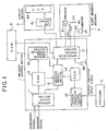
message control section 35 of the prior art paging receiver is shown. In response to the coincidence signal from thedecoder 34, amessage decoding section 351 decodes the message signal and then supplies the decoded signal to a messagestore supervising section 352 at which the decoded signal is stored in a predetermined format. At the same time, a notification drive signal is fed from the messagestore supervising section 352 to annotification control section 353. In response, thecontrol section 353 triggers thedisplay section 4 andalert generating section 5 depending upon the status of aswitch 39. More specifically, the display of a message on thedisplay section 4 and the generation of an alert by the alert generatingsection 5 depends upon the operation of theswitch 39. However, the prior art paging receiver with such a message control section is incapable of allowing the user to adopt or reject the message signal as desired, as discussed earlier. - Referring to Fig. 1, a paging receiver embodying the present invention is shown and includes a message control circuit (section) 1 which is implemented by a 1-chip central processing unit (CPU). Connected to the
message control circuit 1 are akeyboard 2, aRAM 3 for storing a message, adisplay section 4, and analert generating section 5. Thedisplay section 4 is constituted by a liquid crystal display (LCD) 42 and anLCD driver 41 while thealert generating section 5 is comprised of aspeaker 51, a light emitting diode (LED) 52, and avibrator 53. It is to be noted that themessage control circuit 1 is preceded by circuitry which includes theantenna 31, receivingsection 32, P-ROM 33 anddecoder 34 as shown in Fig. 7. - The
message control circuit 1 includes abuffer RAM 12 for temporarily storing a message, amessage searching section 13, and aRAM 14 for storing a search condition and an alerting means, in addition to the various blocks shown in Fig. 8. Themessage searching section 13, amessage decoding section 11, a searchcondition decoding section 15, a messagestore supervising section 16 and anotification control section 17 are software blocks which may be implemented as a program of the centrol processing unit (CPU). - In operation, the
message decoding section 11 of themessage control circuit 1 decodes a message signal in response to a coincidence signal which is outputted by a decoder which precedes themessage decoding section 11. The decoded message signal is temporarily stored in theRAM 12. The message signal lodged in theRAM 12 is searched by themessage searching section 13 according to a search condition which has been stored in theRAM 14 beforehand in a predetermined format. - The search condition is entered on the
keyboard 2 by the user as needed. The search condition is decoded by the searchcondition decoding section 15 and then stored in theRAM 14. Alert generating means such as speaker means, LED means or vibrator means is set via thekeyboard 2 in addition to the search condition. Further entered on thekeyboard 2 is whether or not to store a message received. The result of these settings are also decoded by the searchcondition decoding section 15 and then stored in theRAM 14. - The timing for the
message searching section 13 to begin a search is provided by themessage decoding section 11 in the form of a search start signal. More specifically, when messages are to be searched one after another, the search start signal is outputted timed to the entry of a message in themessage decoding section 11; when they are to be searched on a group basis, the search start signal is produced timed to the end of a sequence of messages. - The
message searching section 13 ends the condition search according to the condition set beforehand and directly delivers the result of search and a signal which designates notifying means associated with the result of search to thenotification control section 17. When a message stored request is entered, themessage searching section 13 feeds a message store request to the messagestore supervising section 16 and writes the content of theRAM 12 in theRAM 3 via thesection 16 while feeding the result of search to the alertnotification control section 17 as stated above. More specifically, the messagestore supervising section 16 reads out of theRAM 12 only a message for which the store request is meant and transfers it to theRAM 3. - Upon reception of the result of search and the particular notifying means, the
notification control section 17 applies a first drive signal to thedisplay section 4 and/or the alert generatingsection 5 with no regard to the status of a message read-out switch 39. Nevertheless, when the result of search is not fed from themessage searching section 13 to thenotification control section 17 and theswitch 39 is conditioned to deliver a message read-out command, thenotification control section 17 reads out the content of theRAM 3 and, based on it, delivers a second drive signal to thedisplay section 4 only. - Any desired kind of combination of the
display section 4 and alert generatingsection 5 which are responsive to the first drive signal may be entered on thekeyboard 2. In response to the first or second drive signal, thedisplay section 4 displays a message on theLCD 42 via theLCD driver 41. Thealert generating section 5 received the first drive signal, more specifically thespeaker 51, LED 52 orvibrator 53 received the drive signal which is associated with the particular alerting means entered on thekeyboard 2, generates an alert. - As stated earlier, the
keyboard 2 is available for the following purposes: - (1) setting a search condition (inclusive of no search condition) and notifying means;
- (2) setting whether or not to store a message;
- (3) setting ON/OFF of notifying means; and
- (4) setting ON/OFF of display.
- While keys for implementing the settings (3) and (4) have to be provided on a casing of the receiver from the practical use standpoint, keys for achieving the purposes (1) and (2) may either be provided on the casing or be implemented by a keyboard of an external terminal as desired. When use is made of an external terminal, it is of course necessary to provide the receiver body with a terminal for connection. By operating such a keyboard, the user is capable of changing the content of the
RAM 14. The previously mentioned message read-out key 39 is provided on the receiver casing independently of the keys for implementing the settings (1) to (4). - The operation of the
message searching section 13 shown in Fig. 1 will now be described with reference to Figs. 2A and 2B. Examples of searches which themessage searching section 13 may perform are as follows: - (1) determining whether or not a specified character train is included in a message;
- (2) evaluating a value represented by a numerical data training which is included in a message; and
- (3) searching for a specified character train and evaluating a value of a numerical data train which immediately follows the character train.
- Operation flows representative of the above-mentioned three examples will be described hereinafter.
- Referring to Fig. 2A, when a search start signal from the
message decoding section 11 arrives in astep 62, the program advances to astep 63. So long as the search start signal does not arrive, thestep 62 is repeated. If the search condition stored in theRAM 14 is a numeral search mode as decided in thestep 63, astep 64 is executed for reading a numercal condition to be searched out of theRAM 14. This is followed by astep 65, i.e., searching for only a numerical data train out of the message from theRAM 12. At thenext step 66, a numerical data train satisfying the above-mentioned numeral condition is searched for. If such a numerical data train is not found in thestep 66, the program is transferred to astep 67 to end the processing. If a numerical data train satisfying the condition is found, astep 68 is executed for reading out from theRAM 14 particular notifying means which has been memorized on the basis of the previously stated search condition. - In the
subsequent step 74, the presence/absence of a message store request is determined by checking theRAM 14. If a message store request is present, a message store request is delivered to the messagestore supervising section 16 at astep 75 and then astep 76 is executed. If such a request is absent thestep 74 is immediately followed by thestep 76. In thestep 76, whether an alert generate request is present is decided on the basis of the content of theRAM 14 and, if it is present, the program advances to astep 77. In thestep 77, a drive request meant for the alert generating means which has been selected by thestep 68 and other steps associated therewith is fed to thenotification control section 17, followed by astep 78. If the alert generate request is absent as decided in thestep 76, the program is directly transferred to thestep 78. In thestep 78, if a display request associated with thedisplay section 4 is present is decided by referencing theRAM 14 and, if it is present, astep 79 is executed for delivering a message display request to thenotification control section 17. If the display request is absent, the operation advances directly to thestep 80 to complete the processing. - If the search mode selected is a character search mode as decided in the
step 63, substantially the same sequence of steps as the steps described above in relation to a numeral search mode are performed. Specifically, astep 69 is executed for reading a character condition to be searched out of theRAM 14. This is followed by astep 70, i.e., searching for only a character data train out of the message from theRAM 12. At the next step 71, a character data train satisfying the above-mentioned character condition is searched for. If such a character data train is not found in the step 71, the program is transferred to astep 72 to end the processing. If a character data train satisfying the condition is found, astep 73 is executed for reading out from theRAM 14 particular notifying means which has been memorized on the basis of the previously stated search condition. Thestep 73 is followed by thestep 74 after which the same steps as the numerical search mode are executed. - Further, in an character and numeral search mode as decided in the
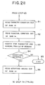
step 63, the program is transferred to astep 91 shown in Fig. 2B for reading a character condition to be searched out of theRAM 14. In Fig. 2B, astep 92 is executed after thestep 91 for reading a numerical condition out of theRAM 14. This is followed by astep 93 for searching for a character data train and a numeral data train out of the message stored in theRAM 12 and, then, by astep 94 for searching for a character data train and a numeral data train which satisfy both of the character and numerical conditions loaded in theRAM 14. In thenext step 96, a notifying means associated with the searched character data train and numeral data train is read out of theRAM 14 and, then, a step 74 (Fig. 2A) is executed. If no character data train and numeral data train which satisfy the condition are not found in thestep 94, the program is transferred to astep 95 to end the processing. - When no particular search condition is entered on the
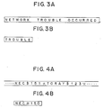
keyboard 2, thesteps 91 to 96 shown in Fig. 2B are executed. In this case, a condition that all the character and numerical data train should be searched will be set in thestep 94. - Referring to Figs. 3A, 3B, 4A and 4B, there are shown practical examples of a character message and a numerical message together with a method of searching them. Assume that a message information offerer (firm) transmits a message "NETWORK TROUBLE OCCURRED" shown in Fig. 3A for informing the user of the paging receiver of the occurrence of some trouble. The user, on the other hand, loads the receiver with a character condition "TROUBLE" to be searched for, as shown in Fig. 3B. In this condition, the receiver searches for a character data train "TROUBLE" out of a received message in the step 71 of the character search mode flow shown in Fig. 2. When the receiver has found the character data train "TROUBLE", it displays the message "NETWORK TROUBLE OCCURRED" and/or generates an alert.
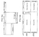
- On the other hand, assume that a stock information offerer (firm) offers the user of the paging receiver stock information such as shown in Fig. 4A, that the stock information is constituted by "stock or security name" and "stock price" which occur in this order, and that the stock or security name is variable in length while the stock price is preceded by a symbol "$" and followed by a symbol "*". In this case, the user of the receiver enters a character and numeral (alphanumeric) search conditions "NEC ≧ 150" shown in Fig. 4B on the
keyboard 2. Then, the receiver searches the stock information in thestep 94 of the character and numeral search flow shown in Fig. 2B. More specifically, the receiver searches for the stock name "NEC" and then, based on the numerical search condition " ≧ 150", the stock price "150" which is sandwiched between the symbols "$" and "*", out of the received stock information. Since the stock name "NEC" and stock price "151" satisfy the search condition "NEC" and "≧ 150", respectively, the receiver displays the message "NEC $150*", produces an alert and/or stores the message in the memory. - As regards the signal format for the transmission of a character and numeral message, the illustrative embodiment uses POCSAG Digital Paging Signal format which is well known in the art. As shown in Fig. 5A, this kind of signal consists of a preamble having at least 576 bits of repetitive ONEs and ZEROs and at least one, usually a plurality of, batches which follow the preamble and are associated with the amount of message information transmitted. Each batch begins with one codeword of SC (Synchronization Codeword) and has sixteen codewords (i.e. eight frames) which follow the SC.
- Fig. 5B shows the format of a codeword mentioned above. As shown, thirty-two bits are assigned to one codeword. Concerning an address code word, a message flag is assigned to a bit No. 1, address bits adapted for a paging number are assigned to bit Nos. 2 to 9, function bits are assigned to bit Nos. 20 and 21, parity check bits are assigned to bit Nos. 22 to 31, and an even parity bit is assigned to a bit No. 32. In the case of a message codeword, a message flag, message bits, parity check bits and even parity bit are assigned to the bit No. 1, bit Nos. 2 to 21, bit Nos. 22 to 31 and bit No. 32, respectively.
- The stock information stated earlier, for eaxmple, is assigned to the message codeword. Fits. 6A to 6C shown bit arrangements for transmitting stock information, taking the stock information of Fig. 4A for example. Let it be assumed that the message characters showing the stock name and price are implemented by an alphanumeric character set shown in Table 1 below (ASCII 7-bit code; CCITT international alphabet No. 5).

- Figs. 6A, 6B, and 6C show respectively the bit construction of a first message in a
frame 1 of the first batch, the bit construction of a second message in aframe 2 of the first btach, and the bit construction of a third message codeword in theframe 2 of the first batch. - In summary, in accordance with the present invention, a message received by a paging receiver is compared on the basis of a particular condition set by a user of the receiver so that the storage of the message in a memory, generation of an alert and the like are controlled depending upon the result of comparison. This allows the user to readily select and therefore immediately see only desired one of incoming information. Especially, when the receiver receives information which is offered to many and unspecified users such as stock there can be realized a function of storing only a message containing only a desired issue, a function of energizing a speaker only when the price of a desired strock or security has gone up beyond a certain price, and function of simply storing a message in other conditions.
Claims (9)
receiving means for receiving a paging number and a message which follows said paging number to produce a received paging number and a received message signal, respectively;
paging number storing means for storing an own paging number assigned to said receiver;
paging number detecting means for comparing said received paging number and said own paging number, if the two paging numbers are identical, producing a coincidence signal and outputting said received message signal;
message decoding means for decoding, in response to said coincidence signal, said received message and generating a decoded message signal;
search condition setting means for setting a search condition and notifying means associated with said search condition, respectively;
search condition decoding means for decoding respectively the set search condition and the set notifying means and outputting respectively a decoded search condition and a decoded notifying means in the form of decoded condition signals;
message selecting means for searching, in response to said decoded message signal and said decoded condition signals, for said decoded message signal on the basis of said decoded search condition which is contained in said decoded condition signals and outputting as a searched message signal the decoded message signal and a notifying signal which is representative of said notifying means associated with said searched message signal;
searched message storing means for storing said searched message signal;
notification control means for, in response to said searched message signal and said notifying signal from said message selecting means, generating a first drive signal and, in response to said searched message signal stored in said searched message storing means, generating a second drive signal;
switching means for commanding selection of one of said first and second drive signals which are generated by said notification control means;
display means for displaying said searched message signal in response to one of said first and second drive signals; and
alert generating means for generating an alert in response to said first drive signal.
receiving means for receiving a paging number and a message which follows said paging number to produce a received paging number and a received message signal, respectively;
paging number storing means for storing an own paging number assigned to said receiver;
paging number detecting means for comparing said received paging number and said own paging number, if said two paging numbers are identical, producing a coincidence signal and outputting said received message signal;
message decoding means for decoding, in response to said coincidence signal, said received message and generating a decoded message signal;
search condition setting means for setting a search condition and notifying means associated with said search condition, respectively;
search condition decoding means for decoding respectively the set search condition and the set notifying means and outputting respectively a decoded search condition and a notifying means in the form of decoded condition signals;
message selecting means for searching, in response to said decoded message signal and decoded condition signals, for the decoded message signal on the basis of said search condition contained in said decoded condition signals and producing a searched message signal which satisfy said search conditions and a notifying signal which is representative of said notifying means associated with said searched message signal; and
means for performing one of the displaying of a message and the generating of an alert in response to said searched message signal and said notifying signal.
receiving means for receiving a paging number and a message signal which follows said paging number to produce a received paging number and a received message signal, respectively;
first search condition means loaded with an own paging number which is assigned to said receiver;
first detecting means for comparing said received paging number and the own paging number and, if said two paging numbers are identical, outputting said received message signal;
second search condition means for setting a condition for searching for said message signal;
second detecting means for comparing said received message signal and said search condition to detect the message signal which satisfies said search condition and outputting said message signal as a control signal; and
means for performing one of the displaying of a message and the generating of an alert in response to said control signal.
Applications Claiming Priority (2)
| Application Number | Priority Date | Filing Date | Title |
|---|---|---|---|
| JP62286751A JP2776503B2 (en) | 1987-11-13 | 1987-11-13 | Radio selective call receiver |
| JP286751/87 | 1987-11-13 |
Publications (3)
| Publication Number | Publication Date |
|---|---|
| EP0317230A2 true EP0317230A2 (en) | 1989-05-24 |
| EP0317230A3 EP0317230A3 (en) | 1990-06-13 |
| EP0317230B1 EP0317230B1 (en) | 1995-03-22 |
Family
ID=17708567
Family Applications (1)
| Application Number | Title | Priority Date | Filing Date |
|---|---|---|---|
| EP88310716A Expired - Lifetime EP0317230B1 (en) | 1987-11-13 | 1988-11-14 | Paging receiver with a message selecting circuit |
Country Status (7)
| Country | Link |
|---|---|
| EP (1) | EP0317230B1 (en) |
| JP (1) | JP2776503B2 (en) |
| KR (1) | KR920001541B1 (en) |
| AU (1) | AU623612B2 (en) |
| CA (1) | CA1331207C (en) |
| DE (1) | DE3853405T2 (en) |
| HK (1) | HK84497A (en) |
Cited By (18)
| Publication number | Priority date | Publication date | Assignee | Title |
|---|---|---|---|---|
| EP0404007A2 (en) * | 1989-06-19 | 1990-12-27 | Nec Corporation | Method for superimposing independently transmitted data on pager display |
| EP0467431A1 (en) * | 1990-07-17 | 1992-01-22 | Ericsson Radio Systems B.V. | Personal paging system |
| US5146216A (en) * | 1989-12-14 | 1992-09-08 | Motorola, Inc. | Multiple message signalling protocol for a selective call receiver |
| EP0504303A1 (en) * | 1989-12-05 | 1992-09-23 | Motorola, Inc. | Selective call receiver theft protection device |
| FR2690028A1 (en) * | 1992-04-13 | 1993-10-15 | Micropross Sarl | Digital data transmission method for radio - using filters matched to specific codes from transmitter allowing release and routing of information |
| EP0574423A1 (en) * | 1991-03-04 | 1993-12-22 | Motorola, Inc. | Selective call receiver having user defined message information in memory and presentation methods thereof |
| EP0592180A1 (en) * | 1992-10-05 | 1994-04-13 | Nec Corporation | Paging receiver |
| EP0593277A1 (en) * | 1992-10-13 | 1994-04-20 | Nec Corporation | Radio paging receiver |
| EP0622764A1 (en) * | 1993-03-30 | 1994-11-02 | Nec Corporation | Radio pager capable of displaying fixed sentences |
| FR2727810A1 (en) * | 1994-12-02 | 1996-06-07 | Dangreaux Pierre | TRANSFER OF FILTERED AUTOMATIC INFORMATION |
| WO1997049192A1 (en) * | 1996-06-21 | 1997-12-24 | Fabio Agnetelli | Electronic apparatus for facilitating communications and meetings among two or more people, commercial transactions, job application/offer |
| US5764157A (en) * | 1992-07-09 | 1998-06-09 | Nec Corporation | Radio paging receiver with display unit having update means to eliminate redundant messages |
| EP0869461A2 (en) * | 1997-03-31 | 1998-10-07 | Casio Computer Co., Ltd. | Data receiving apparatus and received data processing method for use therein |
| EP0876009A1 (en) * | 1996-02-29 | 1998-11-04 | Matsushita Electric Industrial Co., Ltd. | Radio-calling device capable of setting flexibly output mode |
| WO2000014715A1 (en) * | 1998-09-04 | 2000-03-16 | Motorola Inc. | Information message display method |
| WO2001065514A1 (en) * | 2000-03-01 | 2001-09-07 | Dmitry Vyacheslavovich Zhurin | Cap-signaling device |
| US8432276B2 (en) | 2004-07-30 | 2013-04-30 | Elmar Trefz | System and apparatus for alerting a user in response to environmental conditions |
| CN113920678A (en) * | 2021-10-19 | 2022-01-11 | 深圳市盛邦通信有限公司 | Remote smoke alarm system on M5311 chip based on middle moving object |
Families Citing this family (1)
| Publication number | Priority date | Publication date | Assignee | Title |
|---|---|---|---|---|
| JP2755334B2 (en) * | 1990-05-14 | 1998-05-20 | 日本電気株式会社 | Radio paging selection receiver |
Citations (3)
| Publication number | Priority date | Publication date | Assignee | Title |
|---|---|---|---|---|
| EP0126704A2 (en) * | 1983-05-23 | 1984-11-28 | Carrier Corporation | Annunciator |
| EP0135783A2 (en) * | 1983-08-18 | 1985-04-03 | Nec Corporation | Radio communication apparatus disabled on reception of a predetermined signal |
| EP0155628A1 (en) * | 1984-03-13 | 1985-09-25 | Nec Corporation | Paging receivers |
Family Cites Families (2)
| Publication number | Priority date | Publication date | Assignee | Title |
|---|---|---|---|---|
| JPS6116636A (en) * | 1984-07-03 | 1986-01-24 | Nec Corp | Selective call receiver with display function |
| JPS6167334A (en) * | 1984-09-11 | 1986-04-07 | Nec Corp | Selective calling receiver with displaying function |
-
1987
- 1987-11-13 JP JP62286751A patent/JP2776503B2/en not_active Expired - Fee Related
-
1988
- 1988-11-11 AU AU25075/88A patent/AU623612B2/en not_active Ceased
- 1988-11-12 KR KR1019880014872A patent/KR920001541B1/en not_active IP Right Cessation
- 1988-11-14 CA CA000583003A patent/CA1331207C/en not_active Expired - Fee Related
- 1988-11-14 DE DE3853405T patent/DE3853405T2/en not_active Expired - Fee Related
- 1988-11-14 EP EP88310716A patent/EP0317230B1/en not_active Expired - Lifetime
-
1997
- 1997-06-19 HK HK84497A patent/HK84497A/en not_active IP Right Cessation
Patent Citations (3)
| Publication number | Priority date | Publication date | Assignee | Title |
|---|---|---|---|---|
| EP0126704A2 (en) * | 1983-05-23 | 1984-11-28 | Carrier Corporation | Annunciator |
| EP0135783A2 (en) * | 1983-08-18 | 1985-04-03 | Nec Corporation | Radio communication apparatus disabled on reception of a predetermined signal |
| EP0155628A1 (en) * | 1984-03-13 | 1985-09-25 | Nec Corporation | Paging receivers |
Cited By (28)
| Publication number | Priority date | Publication date | Assignee | Title |
|---|---|---|---|---|
| EP0404007A2 (en) * | 1989-06-19 | 1990-12-27 | Nec Corporation | Method for superimposing independently transmitted data on pager display |
| EP0404007A3 (en) * | 1989-06-19 | 1991-06-05 | Nec Corporation | Method for superimposing independently transmitted data on pager display |
| AU635539B2 (en) * | 1989-06-19 | 1993-03-25 | Nec Electronics Corporation | Method for superimposing independently transmitted data on pager display |
| EP0504303A1 (en) * | 1989-12-05 | 1992-09-23 | Motorola, Inc. | Selective call receiver theft protection device |
| EP0504303A4 (en) * | 1989-12-05 | 1993-02-03 | Motorola, Inc. | Selective call receiver theft protection device |
| US5146216A (en) * | 1989-12-14 | 1992-09-08 | Motorola, Inc. | Multiple message signalling protocol for a selective call receiver |
| EP0467431A1 (en) * | 1990-07-17 | 1992-01-22 | Ericsson Radio Systems B.V. | Personal paging system |
| EP0574423A1 (en) * | 1991-03-04 | 1993-12-22 | Motorola, Inc. | Selective call receiver having user defined message information in memory and presentation methods thereof |
| EP0574423A4 (en) * | 1991-03-04 | 1995-05-10 | Motorola Inc | Selective call receiver having user defined message information in memory and presentation methods thereof. |
| FR2690028A1 (en) * | 1992-04-13 | 1993-10-15 | Micropross Sarl | Digital data transmission method for radio - using filters matched to specific codes from transmitter allowing release and routing of information |
| US5764157A (en) * | 1992-07-09 | 1998-06-09 | Nec Corporation | Radio paging receiver with display unit having update means to eliminate redundant messages |
| EP0592180A1 (en) * | 1992-10-05 | 1994-04-13 | Nec Corporation | Paging receiver |
| US5493602A (en) * | 1992-10-05 | 1996-02-20 | Nec Corporation | Paging receiver capable of avoiding disturbance raised on reception of an unnecessary message |
| CN1062696C (en) * | 1992-10-05 | 2001-02-28 | 日本电气株式会社 | Paging receiver capable of avoiding disturbance raised on reception of an unnecessary message |
| EP0593277A1 (en) * | 1992-10-13 | 1994-04-20 | Nec Corporation | Radio paging receiver |
| EP0622764A1 (en) * | 1993-03-30 | 1994-11-02 | Nec Corporation | Radio pager capable of displaying fixed sentences |
| US5652572A (en) * | 1993-03-30 | 1997-07-29 | Nec Corporation | Radio pager capable of displaying fixed sentences |
| FR2727810A1 (en) * | 1994-12-02 | 1996-06-07 | Dangreaux Pierre | TRANSFER OF FILTERED AUTOMATIC INFORMATION |
| EP0876009A1 (en) * | 1996-02-29 | 1998-11-04 | Matsushita Electric Industrial Co., Ltd. | Radio-calling device capable of setting flexibly output mode |
| EP0876009A4 (en) * | 1996-02-29 | 2000-09-27 | Matsushita Electric Ind Co Ltd | Radio-calling device capable of setting flexibly output mode |
| WO1997049192A1 (en) * | 1996-06-21 | 1997-12-24 | Fabio Agnetelli | Electronic apparatus for facilitating communications and meetings among two or more people, commercial transactions, job application/offer |
| EP0869461A2 (en) * | 1997-03-31 | 1998-10-07 | Casio Computer Co., Ltd. | Data receiving apparatus and received data processing method for use therein |
| EP0869461A3 (en) * | 1997-03-31 | 2000-02-23 | Casio Computer Co., Ltd. | Data receiving apparatus and received data processing method for use therein |
| CN100385800C (en) * | 1997-03-31 | 2008-04-30 | 卡西欧计算机株式会社 | Data receiving method |
| WO2000014715A1 (en) * | 1998-09-04 | 2000-03-16 | Motorola Inc. | Information message display method |
| WO2001065514A1 (en) * | 2000-03-01 | 2001-09-07 | Dmitry Vyacheslavovich Zhurin | Cap-signaling device |
| US8432276B2 (en) | 2004-07-30 | 2013-04-30 | Elmar Trefz | System and apparatus for alerting a user in response to environmental conditions |
| CN113920678A (en) * | 2021-10-19 | 2022-01-11 | 深圳市盛邦通信有限公司 | Remote smoke alarm system on M5311 chip based on middle moving object |
Also Published As
| Publication number | Publication date |
|---|---|
| DE3853405T2 (en) | 1995-07-27 |
| EP0317230A3 (en) | 1990-06-13 |
| CA1331207C (en) | 1994-08-02 |
| HK84497A (en) | 1997-06-27 |
| DE3853405D1 (en) | 1995-04-27 |
| AU623612B2 (en) | 1992-05-21 |
| JPH01128627A (en) | 1989-05-22 |
| AU2507588A (en) | 1989-05-18 |
| EP0317230B1 (en) | 1995-03-22 |
| KR890009102A (en) | 1989-07-15 |
| KR920001541B1 (en) | 1992-02-18 |
| JP2776503B2 (en) | 1998-07-16 |
Similar Documents
| Publication | Publication Date | Title |
|---|---|---|
| EP0317230B1 (en) | Paging receiver with a message selecting circuit | |
| EP0572415B1 (en) | Multiple format signalling protocol for a selective call receiver | |
| US5173688A (en) | Pager with display updateable by incoming message | |
| US5087905A (en) | Method for superimposing independently transmitted data on pager display | |
| US5754119A (en) | Multiple pager status synchronization system and method | |
| US5844498A (en) | Paging receiver with a message selection circuit | |
| KR100267699B1 (en) | Data receiver device | |
| US6215980B1 (en) | Apparatus and method for saving battery power of a paging receiver | |
| US5920271A (en) | Radio pager for displaying text message in different fonts and method thereof | |
| KR950011078B1 (en) | Selective calling system | |
| JPH04257127A (en) | Selective call receiver | |
| US6459359B1 (en) | Communication apparatus capable of displaying the number of unconfirmed messages | |
| US5892456A (en) | Index managing method and apparatus of received messages for a radio paging receiver | |
| JPH08502872A (en) | Method for transmitting message and communication system for transmitting message | |
| US5493602A (en) | Paging receiver capable of avoiding disturbance raised on reception of an unnecessary message | |
| US6323754B1 (en) | Two-way telecommunications system | |
| US5864299A (en) | Method and apparatus for reducing overhead in a messaging system | |
| JP2737283B2 (en) | Radio selective call receiver | |
| JPH06177772A (en) | Digital communication system and receiving apparatus used for it | |
| JPH1079966A (en) | Receiver | |
| KR0164364B1 (en) | Apparatus and method of controlling transmitting data in bidirectional wireless pager | |
| KR100218595B1 (en) | Pager having a reminder book function | |
| JP2968732B2 (en) | Radio selective call receiver and recall method | |
| KR100193852B1 (en) | How to change the contents of YPIROM in wireless hand signal generator | |
| US6223020B1 (en) | Destination non-limiting bidirectional radio paging system and method |
Legal Events
| Date | Code | Title | Description |
|---|---|---|---|
| PUAI | Public reference made under article 153(3) epc to a published international application that has entered the european phase |
Free format text: ORIGINAL CODE: 0009012 |
|
| 17P | Request for examination filed |
Effective date: 19881206 |
|
| AK | Designated contracting states |
Kind code of ref document: A2 Designated state(s): DE GB NL |
|
| PUAL | Search report despatched |
Free format text: ORIGINAL CODE: 0009013 |
|
| AK | Designated contracting states |
Kind code of ref document: A3 Designated state(s): DE GB NL |
|
| 17Q | First examination report despatched |
Effective date: 19921020 |
|
| GRAA | (expected) grant |
Free format text: ORIGINAL CODE: 0009210 |
|
| AK | Designated contracting states |
Kind code of ref document: B1 Designated state(s): DE GB NL |
|
| REF | Corresponds to: |
Ref document number: 3853405 Country of ref document: DE Date of ref document: 19950427 |
|
| PLBE | No opposition filed within time limit |
Free format text: ORIGINAL CODE: 0009261 |
|
| STAA | Information on the status of an ep patent application or granted ep patent |
Free format text: STATUS: NO OPPOSITION FILED WITHIN TIME LIMIT |
|
| 26N | No opposition filed | ||
| PGFP | Annual fee paid to national office [announced via postgrant information from national office to epo] |
Ref country code: NL Payment date: 20001130 Year of fee payment: 13 |
|
| REG | Reference to a national code |
Ref country code: GB Ref legal event code: IF02 |
|
| PG25 | Lapsed in a contracting state [announced via postgrant information from national office to epo] |
Ref country code: NL Free format text: LAPSE BECAUSE OF NON-PAYMENT OF DUE FEES Effective date: 20020601 |
|
| NLV4 | Nl: lapsed or anulled due to non-payment of the annual fee |
Effective date: 20020601 |
|
| PGFP | Annual fee paid to national office [announced via postgrant information from national office to epo] |
Ref country code: GB Payment date: 20051109 Year of fee payment: 18 |
|
| PGFP | Annual fee paid to national office [announced via postgrant information from national office to epo] |
Ref country code: DE Payment date: 20051110 Year of fee payment: 18 |
|
| PG25 | Lapsed in a contracting state [announced via postgrant information from national office to epo] |
Ref country code: DE Free format text: LAPSE BECAUSE OF NON-PAYMENT OF DUE FEES Effective date: 20070601 |
|
| GBPC | Gb: european patent ceased through non-payment of renewal fee |
Effective date: 20061114 |
|
| PG25 | Lapsed in a contracting state [announced via postgrant information from national office to epo] |
Ref country code: GB Free format text: LAPSE BECAUSE OF NON-PAYMENT OF DUE FEES Effective date: 20061114 |