EP0239364A2 - A drive system for a bending machine - Google Patents
A drive system for a bending machine Download PDFInfo
- Publication number
- EP0239364A2 EP0239364A2 EP87302531A EP87302531A EP0239364A2 EP 0239364 A2 EP0239364 A2 EP 0239364A2 EP 87302531 A EP87302531 A EP 87302531A EP 87302531 A EP87302531 A EP 87302531A EP 0239364 A2 EP0239364 A2 EP 0239364A2
- Authority
- EP
- European Patent Office
- Prior art keywords
- speed
- roller
- machine
- rollers
- torque
- Prior art date
- Legal status (The legal status is an assumption and is not a legal conclusion. Google has not performed a legal analysis and makes no representation as to the accuracy of the status listed.)
- Granted
Links
Images

Classifications
-
- B—PERFORMING OPERATIONS; TRANSPORTING
- B21—MECHANICAL METAL-WORKING WITHOUT ESSENTIALLY REMOVING MATERIAL; PUNCHING METAL
- B21D—WORKING OR PROCESSING OF SHEET METAL OR METAL TUBES, RODS OR PROFILES WITHOUT ESSENTIALLY REMOVING MATERIAL; PUNCHING METAL
- B21D7/00—Bending rods, profiles, or tubes
- B21D7/08—Bending rods, profiles, or tubes by passing between rollers or through a curved die
Definitions
- the present invention relates to apparatus for and a method of bending strip metal material such as 'I' section beams and 'U' section beams or other formed sections.
- the first roll normally has a fixed axis on one side of the path, the next or second along the path is on the other side, whilst the third roll is on the same side of the path as the first, the second and third rolls have axes which are adjustable with respect to the bending path.
- Other rolls may also be provided.
- the axes of the rollers are essentially parallel (or sometimes on an angle in order to generate a cone shape) to each other, and are arranged in approximately a triangular pattern so that a strip or sheet like workpiece passed between them is bent in to a curved shape.
- a bending machine will hereafter be referred to as a bending machine of the type described.
- a conventional roll bending machine is driven by a single motor and/or gearbox.
- One or more of the rollers may be driven directly or by shafts, gears, chains etc. and consequently all driven rollers rotate at the same speed or fixed ratio of speeds.
- One or more rollers may not be driven at all and allowed to freewheel.
- the general object of the invention is to eliminate or substantially to eliminate these problems and to enable a bending machine to be readily adjusted accurately to produce bends of differing dimensions.
- a bending machine of the type described in accordance with the invention has for one or more of its rollers (three or more) a means for ascertaining the position of the or each roller, means for adjusting that position, means for measuring the speed of rotation of the or each roller, means for adjusting that speed (and preferably) means for measuring the torque applied to the or each roller and means for adjusting that torque, signals from the means for measuring the position, speed (and preferably) applied torque on the rollers being fed to a control system unit which in turn is connected to the means for adjusting the position, speed and applied torque of the or each roller so that commands may be given to vary these parameters.
- the apparatus may be readily adjusted for any desired arch within limits by giving the control unit the necessary instructions.
- the section to be bent should be driven forward at a reasonable speed with sufficient torque force being applied through the rollers to achieve bending without the rollers slipping and to enable the desired internal force to be generated in the section.
- rollers will be driven at different speeds and/or with differing torques.
- rollers will normally be driven either by independent hydraulic, electrical or pneumatic motors or by or by variable speed drives.
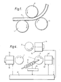
- FIG. 1 a typical three roll arch bending machine of the type described is illustrated but the invention is in no way restricted to such a particular layout.
- Three rolls 1, 2 and 3 are located in a triangular position with an 'I' section beam 4 moved between the rolls in the direction of the arrow.
- the axes of the rolls are movable relative to each other so that they can be positioned to achieve the desired radius of curvature of the bent section.
- each of the three rolls is driven by a separate motor 5, 6 and 7 through gears 8.
- the speed and torque applied to each roll may differ and the relevant speeds may be adjusted during bending of the 'I' section beam.
- each of the rolls 1, 2 and 3 is adjustable by means of a positioning actuator generally indicated at 10 in the direction both of the axis x and the axis y.
- the position of each roll at any one time can be measured by a measuring device generally indicated at 11.
- the speed of rotation of each roll can be adjusted by a rotation actuator (not shown) which in effect can adjust the speed of rotation of each roll through the drive motors 5, 6 and 7 and gearing 8.
- the instant speed of each roll is measured by a measuring device 11.
- Signals from the measuring units 11 of both the position in the x and y directions, the rotational speed and the torque, is fed to a control unit 12.
- the control unit in accordance with instructions which it has received for some particular section and some particular desired radius then issues instructions for alterations to the position, speed and torque of each of the three rolls to adjustment means 13 so as to achieve the desired curvature. This control system continues to operate during the formation of the bend in the section.
- roll 3 could have two units of torque applied to it, roll 2 could have no torque applied and roll 1 could have minus one unit of torque. This would then give the effect of stretching the outer curved face of the section helping to prevent the tendency to crumple and help to prevent elongation of any holes which may be present in the web of the 'I' section along the central zone where deformation tends to occur.
- the rolls are driven by hydraulic motors.
- Roll 1 is provided with a pressure measuring device 14 and a proportional valve pressure control 15 for control over the fluid pressure applied to the motor so that the torque may be varied.
- the position of the proportional valve is set by the control device 17 and the device 14 for measuring pressure is then linked to the device 15 also for controlling the position of the proportional valve.
- Similar controls are provided for the roll 2 but the roll 3 is provided with a hydraulic piston and cylinder device generally indicated at 10 designed to alter the position of roll 3 in both the x and y direction. This device is also linked to a position measuring device 16 giving signals to the control unit 17.
- a fluid pressure measuring device 14 ⁇ is also provided for the fluid flow to the hydraulic motor for roll 3 and the output from this measuring unit is fed to the control unit 17 rather than to the proportional valve pressure control as in the case with rolls 1 and 2.
- a proportional valve flow control unit 15 ⁇ is provided which receives instructions from the control unit 17 so that the speed of rotation of roll 3 may be adjusted.
- control unit 17 issues instructions for alteration of the torques applied to rollers 1 and 2, the net torque may not be enough to ensure the movement of the section through the machine at the desired speed, in which case the actual rotation speed of roll 3 will drop.
- Roll 3 may be speed controlled in which case its control valve will increase oil flow to the motor driving roll 3 to correct the speed error; in so doing, the torque that it supplies will automatically increase, ensuring that the net torque supplied by rolls 1,2 and 3 is enough to achieve the correct bend at the correct speed. In this way the overall control system can compensate automatically for any process variations.
- a problem with bending machines of the type described is that on varying the velocity of the rollers, a high frequency gear-box resonance can be excited. This results in poor performance and machine wear.
- An advantage of providing a control system as shown in the drawings for such a bending machine is that the system can be arranged to increase 'roll-off' at high frequencies and thus minimise the effect of the gear-box resonance.
Abstract
Description
- The present invention relates to apparatus for and a method of bending strip metal material such as 'I' section beams and 'U' section beams or other formed sections.
- In order to bend such sections it is conventional to provide three or more rolls which straddle and feed path of the material to be bent. The first roll normally has a fixed axis on one side of the path, the next or second along the path is on the other side, whilst the third roll is on the same side of the path as the first, the second and third rolls have axes which are adjustable with respect to the bending path. Other rolls may also be provided.
- The axes of the rollers are essentially parallel (or sometimes on an angle in order to generate a cone shape) to each other, and are arranged in approximately a triangular pattern so that a strip or sheet like workpiece passed between them is bent in to a curved shape. Such a bending machine will hereafter be referred to as a bending machine of the type described.
- A conventional roll bending machine is driven by a single motor and/or gearbox. One or more of the rollers may be driven directly or by shafts, gears, chains etc. and consequently all driven rollers rotate at the same speed or fixed ratio of speeds. One or more rollers may not be driven at all and allowed to freewheel.
- When bending thin sections or large radius curves this does not present a problem but with small radii and thicker sections the different relative speeds of the outside and inside of the curve results in either slip, distortion of the section or overloading of the gearbox components. When bending large sections this problem is kept to a minimum by passing the workpiece backwards and forwards several times making progressive reductions in radii and permitting some slip on one or more of the rollers.
- If a small radii is attempted in a single pass of the workpiece, the internal forces induced in the workpiece will cause severe and unacceptable deformation. On the other hand, if one or more of the rollers is allowed to freewheel to eliminate slip, then the driven roller(s) will also slip and/or distort the section.
- The general object of the invention is to eliminate or substantially to eliminate these problems and to enable a bending machine to be readily adjusted accurately to produce bends of differing dimensions.
- A bending machine of the type described in accordance with the invention has for one or more of its rollers (three or more) a means for ascertaining the position of the or each roller, means for adjusting that position, means for measuring the speed of rotation of the or each roller, means for adjusting that speed (and preferably) means for measuring the torque applied to the or each roller and means for adjusting that torque, signals from the means for measuring the position, speed (and preferably) applied torque on the rollers being fed to a control system unit which in turn is connected to the means for adjusting the position, speed and applied torque of the or each roller so that commands may be given to vary these parameters.
- Thus complete control over each of the parameters is maintained and as we have discovered that it is these parameters which effect the proper bending of the arch to a determined radius, the apparatus may be readily adjusted for any desired arch within limits by giving the control unit the necessary instructions.
- For example, the section to be bent should be driven forward at a reasonable speed with sufficient torque force being applied through the rollers to achieve bending without the rollers slipping and to enable the desired internal force to be generated in the section.
- It will be appreciated that normally the rollers will be driven at different speeds and/or with differing torques.
- However with one control system unit on each motor it is possible to control either motor pressure or motor speed, but not both simultaneously.
- The rollers will normally be driven either by independent hydraulic, electrical or pneumatic motors or by or by variable speed drives.
- The invention will now be further described by way of example with reference to the accompanying drawings in which:-
- Figure 1 is a diagrammatic view of a three roll bending machine of the type described showing an 'I' section beam being bent to form a colliery arch,
- Figure 2 is a side elevation of the apparatus shown in Figure 1,
- Figure 3 is a schematic view of the apparatus shown in Figures 1 and 2 illustrating the control system,
and - Figure 4 is an example of one particular embodiment of a bending machine incorporating the principles generally illustrated in Figure 3.
- Referring to Figure 1 a typical three roll arch bending machine of the type described is illustrated but the invention is in no way restricted to such a particular layout.
- Three
rolls section beam 4 moved between the rolls in the direction of the arrow. The axes of the rolls are movable relative to each other so that they can be positioned to achieve the desired radius of curvature of the bent section. - As can be seen from Figure 2 each of the three rolls is driven by a
separate motor gears 8. As each roll has its own drive motor the speed and torque applied to each roll may differ and the relevant speeds may be adjusted during bending of the 'I' section beam. - As is illustrated in Figure 3 the position of each of the
rolls - The speed of rotation of each roll can be adjusted by a rotation actuator (not shown) which in effect can adjust the speed of rotation of each roll through the
drive motors measuring device 11. - Finally the torque applied to each roll is both adjustable and measurable.
- Signals from the
measuring units 11 of both the position in the x and y directions, the rotational speed and the torque, is fed to acontrol unit 12. The control unit in accordance with instructions which it has received for some particular section and some particular desired radius then issues instructions for alterations to the position, speed and torque of each of the three rolls to adjustment means 13 so as to achieve the desired curvature. This control system continues to operate during the formation of the bend in the section. - It will be appreciated that for example the torque applied to the various rolls may differ for example for one power unit,
roll 3 could have two units of torque applied to it,roll 2 could have no torque applied androll 1 could have minus one unit of torque. This would then give the effect of stretching the outer curved face of the section helping to prevent the tendency to crumple and help to prevent elongation of any holes which may be present in the web of the 'I' section along the central zone where deformation tends to occur. - In the machine exemplified in Figure 4, the rolls are driven by hydraulic motors.
Roll 1 is provided with apressure measuring device 14 and a proportionalvalve pressure control 15 for control over the fluid pressure applied to the motor so that the torque may be varied. The position of the proportional valve is set by thecontrol device 17 and thedevice 14 for measuring pressure is then linked to thedevice 15 also for controlling the position of the proportional valve. Similar controls are provided for theroll 2 but theroll 3 is provided with a hydraulic piston and cylinder device generally indicated at 10 designed to alter the position ofroll 3 in both the x and y direction. This device is also linked to aposition measuring device 16 giving signals to thecontrol unit 17. - A fluid pressure measuring device 14ʹ is also provided for the fluid flow to the hydraulic motor for
roll 3 and the output from this measuring unit is fed to thecontrol unit 17 rather than to the proportional valve pressure control as in the case withrolls control unit 17 so that the speed of rotation ofroll 3 may be adjusted. - It will thus be appreciated that when
control unit 17 issues instructions for alteration of the torques applied torollers roll 3 will drop.Roll 3 may be speed controlled in which case its control valve will increase oil flow to themotor driving roll 3 to correct the speed error; in so doing, the torque that it supplies will automatically increase, ensuring that the net torque supplied byrolls - A problem with bending machines of the type described is that on varying the velocity of the rollers, a high frequency gear-box resonance can be excited. This results in poor performance and machine wear. An advantage of providing a control system as shown in the drawings for such a bending machine is that the system can be arranged to increase 'roll-off' at high frequencies and thus minimise the effect of the gear-box resonance.
Claims (10)
Applications Claiming Priority (2)
| Application Number | Priority Date | Filing Date | Title |
|---|---|---|---|
| GB8607806 | 1986-03-27 | ||
| GB868607806A GB8607806D0 (en) | 1986-03-27 | 1986-03-27 | Drive system |
Publications (3)
| Publication Number | Publication Date |
|---|---|
| EP0239364A2 true EP0239364A2 (en) | 1987-09-30 |
| EP0239364A3 EP0239364A3 (en) | 1989-06-07 |
| EP0239364B1 EP0239364B1 (en) | 1991-09-25 |
Family
ID=10595420
Family Applications (1)
| Application Number | Title | Priority Date | Filing Date |
|---|---|---|---|
| EP87302531A Expired EP0239364B1 (en) | 1986-03-27 | 1987-03-24 | A drive system for a bending machine |
Country Status (6)
| Country | Link |
|---|---|
| US (1) | US4893489A (en) |
| EP (1) | EP0239364B1 (en) |
| CA (1) | CA1291405C (en) |
| DE (1) | DE3773243D1 (en) |
| DK (1) | DK165491C (en) |
| GB (2) | GB8607806D0 (en) |
Cited By (8)
| Publication number | Priority date | Publication date | Assignee | Title |
|---|---|---|---|---|
| EP0405600A1 (en) * | 1989-06-30 | 1991-01-02 | Hashimoto Forming Industry Co., Ltd. | Method and apparatus for bending manufacturing of long workpiece |
| CN103506444A (en) * | 2012-06-29 | 2014-01-15 | 天津市芳华通讯工程有限公司 | Angle-adjustable channel steel bending machine |
| CN104942086A (en) * | 2015-06-26 | 2015-09-30 | 苏州边桐传感科技有限公司 | Intelligent metal plate bending device and method thereof |
| CN104942068A (en) * | 2015-06-24 | 2015-09-30 | 苏州边桐传感科技有限公司 | Intelligent metal plate bending device |
| WO2016097984A1 (en) * | 2014-12-15 | 2016-06-23 | Mauro Meliga | Bending machine for bending tubes, profiled sections, sheets and the like, with a measuring system for measuring the reaction force applied by the workpiece on the bending roller(s) of the machine |
| WO2018177876A1 (en) * | 2017-03-29 | 2018-10-04 | Can Man Ag | Method for rounding sheet metal blanks for containers and a longitudinal seam welding machine for producing can bodies, comprising a round station |
| CH713656A1 (en) * | 2017-03-29 | 2018-10-15 | Can Man Ag | Method for rounding sheet metal blanks for containers and a longitudinal seam welding machine for the production of can bodies with a round station. |
| IT201800005501A1 (en) * | 2018-05-18 | 2019-11-18 | TRANSMISSION DEVICE AND TORQUE LIMITATION |
Families Citing this family (16)
| Publication number | Priority date | Publication date | Assignee | Title |
|---|---|---|---|---|
| JPH02299722A (en) * | 1989-05-15 | 1990-12-12 | Makoto Murata | Push-through bending method and bending device by this method |
| US5431035A (en) * | 1993-03-10 | 1995-07-11 | Sheen; Reen Y. | Hydraulic pipe bender of large dimension |
| US6029333A (en) * | 1997-12-04 | 2000-02-29 | Ferco Tech Corporation | Method of making an inspection fixture for determining the accuracy of bent tubular parts |
| DE19956796A1 (en) * | 1999-11-25 | 2001-06-13 | Palima W Ludwig & Co | Bending device for 2- and 3-dimensional profile bending |
| GB0115547D0 (en) * | 2001-06-26 | 2001-08-15 | Beaudoin Michel | Skate blade curving device |
| US7337642B2 (en) * | 2005-06-13 | 2008-03-04 | Shape Corporation | Roll-former apparatus with rapid-adjust sweep box |
| CN100435993C (en) * | 2006-02-21 | 2008-11-26 | 吉林大学 | Flexible 3D curved plate bending mechanism with independently driven son roller |
| US20080271509A1 (en) * | 2007-05-01 | 2008-11-06 | R&Y Enterprises, Llc | Computer controlled flexible rolling machine |
| ITRM20080078A1 (en) * | 2008-02-12 | 2009-08-13 | Cml Intarnational S P A | METHOD OF VERIFICATION AND COMMAND TO CURVE IN AN CONTINUOUS WAY A PIECE EXTENDED ACCORDING TO VARIABLE CURCATORS SPOKES AND MACHINE SO COMMANDED |
| US9221088B2 (en) * | 2009-04-21 | 2015-12-29 | Fairmont Technologies, Llc | Stretch roll forming |
| US8333096B2 (en) | 2009-09-21 | 2012-12-18 | Shape Corp. | Method of forming three-dimensional multi-plane beam |
| DE102011054581A1 (en) * | 2011-10-18 | 2013-04-18 | Krauss-Maffei Wegmann Gmbh & Co. Kg | Apparatus and method for providing balance weights |
| CN104588493B (en) * | 2015-01-21 | 2016-05-25 | 上海理工大学 | Set round device and control method thereof |
| US10363590B2 (en) | 2015-03-19 | 2019-07-30 | Machine Concepts, Inc. | Shape correction leveler drive systems |
| CN112517784A (en) * | 2020-11-16 | 2021-03-19 | 吉林大学 | Current-assist-based vehicle-mounted gas cylinder barrel forming plate rolling machine and control method thereof |
| CN114713680B (en) * | 2022-06-09 | 2022-09-13 | 江苏江平新环境科技有限公司 | Special-shaped pipe bending machine for air conditioner |
Citations (3)
| Publication number | Priority date | Publication date | Assignee | Title |
|---|---|---|---|---|
| US4047411A (en) * | 1977-01-03 | 1977-09-13 | The Boeing Company | Numerically controlled pyramid roll forming machine |
| US4132099A (en) * | 1976-01-29 | 1979-01-02 | Chr. Hausler Ag | Four-roller workpiece bending machine |
| US4232540A (en) * | 1979-03-19 | 1980-11-11 | Cain Jack C | Controlled variable radius roll forming apparatus |
Family Cites Families (3)
| Publication number | Priority date | Publication date | Assignee | Title |
|---|---|---|---|---|
| US4080815A (en) * | 1975-06-09 | 1978-03-28 | The Boeing Company | Pinch and forming roll assembly for numerically controlled contour forming machines |
| US4117702A (en) * | 1977-06-06 | 1978-10-03 | The Boeing Company | Rolling machines for contouring tapered structural members |
| US4367640A (en) * | 1980-01-28 | 1983-01-11 | Heitzman Steven C | Apparatus for forming sheet metal duct work |
-
1986
- 1986-03-27 GB GB868607806A patent/GB8607806D0/en active Pending
-
1987
- 1987-03-24 EP EP87302531A patent/EP0239364B1/en not_active Expired
- 1987-03-24 DE DE8787302531T patent/DE3773243D1/en not_active Expired - Fee Related
- 1987-03-24 GB GB8706994A patent/GB2188265B/en not_active Expired
- 1987-03-26 DK DK154387A patent/DK165491C/en not_active IP Right Cessation
- 1987-03-27 CA CA000533167A patent/CA1291405C/en not_active Expired - Lifetime
-
1988
- 1988-03-14 US US07/170,138 patent/US4893489A/en not_active Expired - Fee Related
Patent Citations (3)
| Publication number | Priority date | Publication date | Assignee | Title |
|---|---|---|---|---|
| US4132099A (en) * | 1976-01-29 | 1979-01-02 | Chr. Hausler Ag | Four-roller workpiece bending machine |
| US4047411A (en) * | 1977-01-03 | 1977-09-13 | The Boeing Company | Numerically controlled pyramid roll forming machine |
| US4232540A (en) * | 1979-03-19 | 1980-11-11 | Cain Jack C | Controlled variable radius roll forming apparatus |
Cited By (9)
| Publication number | Priority date | Publication date | Assignee | Title |
|---|---|---|---|---|
| EP0405600A1 (en) * | 1989-06-30 | 1991-01-02 | Hashimoto Forming Industry Co., Ltd. | Method and apparatus for bending manufacturing of long workpiece |
| US5425257A (en) * | 1989-06-30 | 1995-06-20 | Hashimoto Forming Industry Co., Ltd. | Method and apparatus for bending an elongate workpiece |
| CN103506444A (en) * | 2012-06-29 | 2014-01-15 | 天津市芳华通讯工程有限公司 | Angle-adjustable channel steel bending machine |
| WO2016097984A1 (en) * | 2014-12-15 | 2016-06-23 | Mauro Meliga | Bending machine for bending tubes, profiled sections, sheets and the like, with a measuring system for measuring the reaction force applied by the workpiece on the bending roller(s) of the machine |
| CN104942068A (en) * | 2015-06-24 | 2015-09-30 | 苏州边桐传感科技有限公司 | Intelligent metal plate bending device |
| CN104942086A (en) * | 2015-06-26 | 2015-09-30 | 苏州边桐传感科技有限公司 | Intelligent metal plate bending device and method thereof |
| WO2018177876A1 (en) * | 2017-03-29 | 2018-10-04 | Can Man Ag | Method for rounding sheet metal blanks for containers and a longitudinal seam welding machine for producing can bodies, comprising a round station |
| CH713656A1 (en) * | 2017-03-29 | 2018-10-15 | Can Man Ag | Method for rounding sheet metal blanks for containers and a longitudinal seam welding machine for the production of can bodies with a round station. |
| IT201800005501A1 (en) * | 2018-05-18 | 2019-11-18 | TRANSMISSION DEVICE AND TORQUE LIMITATION |
Also Published As
| Publication number | Publication date |
|---|---|
| GB8706994D0 (en) | 1987-04-29 |
| EP0239364B1 (en) | 1991-09-25 |
| DK154387A (en) | 1987-09-28 |
| CA1291405C (en) | 1991-10-29 |
| GB8607806D0 (en) | 1986-04-30 |
| US4893489A (en) | 1990-01-16 |
| DE3773243D1 (en) | 1991-10-31 |
| DK154387D0 (en) | 1987-03-26 |
| DK165491B (en) | 1992-12-07 |
| EP0239364A3 (en) | 1989-06-07 |
| DK165491C (en) | 1993-04-19 |
| GB2188265A (en) | 1987-09-30 |
| GB2188265B (en) | 1989-11-29 |
Similar Documents
| Publication | Publication Date | Title |
|---|---|---|
| EP0239364B1 (en) | A drive system for a bending machine | |
| EP1413371B1 (en) | Coil material feeding apparatus | |
| US4558577A (en) | Roll-forming machine for making articles having cross-sectional configurations varying lengthwise | |
| CA1122305A (en) | Method of and apparatus for producing plate material having uniform width and lengthwise thickness variation | |
| US8127580B2 (en) | Method for levelling a flat product in strip or sheet form in a levelling machine with intermeshed rolls and levelling installation therefore | |
| US3427848A (en) | Devices for cold-rolling and planishing metal sheet | |
| US3962894A (en) | Method of and apparatus for stretching a metal strip | |
| CA1140237A (en) | Roller-dies-processing method and apparatus | |
| EP0196466A2 (en) | Method of and apparatus for feeding material to hot forging machine | |
| US5528917A (en) | Force controlled rolling of gears | |
| US3764050A (en) | Differential drive for tension rollers | |
| US6301946B1 (en) | Strip coiling method | |
| GB2276107A (en) | Method of winding a strip of material | |
| US11752533B2 (en) | Control method of a leveling machine and leveling machine | |
| JPH07256327A (en) | Pinch roll for correcting meandering of strip, device and method for correcting meandering | |
| GB2319489A (en) | Zero force roll release for high speed press feed units | |
| CA1067383A (en) | Tensioning apparatus for continuous strip, especially metal strip and bands | |
| US4593548A (en) | Method of correcting distortions in a rolled strip product | |
| JPH0230762B2 (en) | ||
| JP2003025018A (en) | Leveler feeder line | |
| JP2961453B2 (en) | Optimal tension calculator for printing machines | |
| JP2815216B2 (en) | Side guide control method | |
| JPS5915722B2 (en) | Method and device for controlling the shape and crown near the plate edge in flat plate rolling | |
| JP3298438B2 (en) | Method and apparatus for edging rolling of material for section steel | |
| SU995941A1 (en) | Apparatus for automatic control of strip shape at rolling in mills with individual drive of rolls |
Legal Events
| Date | Code | Title | Description |
|---|---|---|---|
| PUAI | Public reference made under article 153(3) epc to a published international application that has entered the european phase |
Free format text: ORIGINAL CODE: 0009012 |
|
| AK | Designated contracting states |
Kind code of ref document: A2 Designated state(s): BE CH DE FR GB IT LI SE |
|
| PUAL | Search report despatched |
Free format text: ORIGINAL CODE: 0009013 |
|
| AK | Designated contracting states |
Kind code of ref document: A3 Designated state(s): BE CH DE FR GB IT LI SE |
|
| RBV | Designated contracting states (corrected) |
Designated state(s): BE CH DE FR IT LI SE |
|
| 17P | Request for examination filed |
Effective date: 19891124 |
|
| 17Q | First examination report despatched |
Effective date: 19900409 |
|
| GRAA | (expected) grant |
Free format text: ORIGINAL CODE: 0009210 |
|
| AK | Designated contracting states |
Kind code of ref document: B1 Designated state(s): BE CH DE FR IT LI SE |
|
| REF | Corresponds to: |
Ref document number: 3773243 Country of ref document: DE Date of ref document: 19911031 |
|
| ET | Fr: translation filed | ||
| ITF | It: translation for a ep patent filed |
Owner name: MODIANO & ASSOCIATI S.R.L. |
|
| PLBE | No opposition filed within time limit |
Free format text: ORIGINAL CODE: 0009261 |
|
| STAA | Information on the status of an ep patent application or granted ep patent |
Free format text: STATUS: NO OPPOSITION FILED WITHIN TIME LIMIT |
|
| 26N | No opposition filed | ||
| EAL | Se: european patent in force in sweden |
Ref document number: 87302531.6 |
|
| PGFP | Annual fee paid to national office [announced via postgrant information from national office to epo] |
Ref country code: FR Payment date: 19960326 Year of fee payment: 10 |
|
| PGFP | Annual fee paid to national office [announced via postgrant information from national office to epo] |
Ref country code: SE Payment date: 19960327 Year of fee payment: 10 |
|
| PGFP | Annual fee paid to national office [announced via postgrant information from national office to epo] |
Ref country code: DE Payment date: 19960328 Year of fee payment: 10 |
|
| PGFP | Annual fee paid to national office [announced via postgrant information from national office to epo] |
Ref country code: CH Payment date: 19960412 Year of fee payment: 10 |
|
| PGFP | Annual fee paid to national office [announced via postgrant information from national office to epo] |
Ref country code: BE Payment date: 19960510 Year of fee payment: 10 |
|
| PG25 | Lapsed in a contracting state [announced via postgrant information from national office to epo] |
Ref country code: SE Effective date: 19970325 |
|
| PG25 | Lapsed in a contracting state [announced via postgrant information from national office to epo] |
Ref country code: LI Effective date: 19970331 Ref country code: CH Effective date: 19970331 Ref country code: BE Effective date: 19970331 |
|
| BERE | Be: lapsed |
Owner name: CALEDONIAN MINING CY LTD Effective date: 19970331 |
|
| REG | Reference to a national code |
Ref country code: CH Ref legal event code: PL |
|
| PG25 | Lapsed in a contracting state [announced via postgrant information from national office to epo] |
Ref country code: FR Free format text: LAPSE BECAUSE OF NON-PAYMENT OF DUE FEES Effective date: 19971128 |
|
| PG25 | Lapsed in a contracting state [announced via postgrant information from national office to epo] |
Ref country code: DE Effective date: 19971202 |
|
| EUG | Se: european patent has lapsed |
Ref document number: 87302531.6 |
|
| REG | Reference to a national code |
Ref country code: FR Ref legal event code: ST |
|
| PG25 | Lapsed in a contracting state [announced via postgrant information from national office to epo] |
Ref country code: IT Free format text: LAPSE BECAUSE OF NON-PAYMENT OF DUE FEES;WARNING: LAPSES OF ITALIAN PATENTS WITH EFFECTIVE DATE BEFORE 2007 MAY HAVE OCCURRED AT ANY TIME BEFORE 2007. THE CORRECT EFFECTIVE DATE MAY BE DIFFERENT FROM THE ONE RECORDED. Effective date: 20050324 |