EP0237457A1 - Exit controlling and monitoring system - Google Patents
Exit controlling and monitoring system Download PDFInfo
- Publication number
- EP0237457A1 EP0237457A1 EP87460001A EP87460001A EP0237457A1 EP 0237457 A1 EP0237457 A1 EP 0237457A1 EP 87460001 A EP87460001 A EP 87460001A EP 87460001 A EP87460001 A EP 87460001A EP 0237457 A1 EP0237457 A1 EP 0237457A1
- Authority
- EP
- European Patent Office
- Prior art keywords
- time delay
- control
- opening
- circuit
- central station
- Prior art date
- Legal status (The legal status is an assumption and is not a legal conclusion. Google has not performed a legal analysis and makes no representation as to the accuracy of the status listed.)
- Withdrawn
Links
Images


Classifications
-
- E—FIXED CONSTRUCTIONS
- E05—LOCKS; KEYS; WINDOW OR DOOR FITTINGS; SAFES
- E05B—LOCKS; ACCESSORIES THEREFOR; HANDCUFFS
- E05B65/00—Locks or fastenings for special use
- E05B65/10—Locks or fastenings for special use for panic or emergency doors
- E05B65/108—Electronically controlled emergency exits
-
- G—PHYSICS
- G08—SIGNALLING
- G08B—SIGNALLING OR CALLING SYSTEMS; ORDER TELEGRAPHS; ALARM SYSTEMS
- G08B13/00—Burglar, theft or intruder alarms
- G08B13/02—Mechanical actuation
- G08B13/08—Mechanical actuation by opening, e.g. of door, of window, of drawer, of shutter, of curtain, of blind
-
- G—PHYSICS
- G08—SIGNALLING
- G08B—SIGNALLING OR CALLING SYSTEMS; ORDER TELEGRAPHS; ALARM SYSTEMS
- G08B25/00—Alarm systems in which the location of the alarm condition is signalled to a central station, e.g. fire or police telegraphic systems
- G08B25/01—Alarm systems in which the location of the alarm condition is signalled to a central station, e.g. fire or police telegraphic systems characterised by the transmission medium
- G08B25/014—Alarm signalling to a central station with two-way communication, e.g. with signalling back
-
- G—PHYSICS
- G08—SIGNALLING
- G08B—SIGNALLING OR CALLING SYSTEMS; ORDER TELEGRAPHS; ALARM SYSTEMS
- G08B25/00—Alarm systems in which the location of the alarm condition is signalled to a central station, e.g. fire or police telegraphic systems
- G08B25/01—Alarm systems in which the location of the alarm condition is signalled to a central station, e.g. fire or police telegraphic systems characterised by the transmission medium
- G08B25/016—Personal emergency signalling and security systems
-
- Y—GENERAL TAGGING OF NEW TECHNOLOGICAL DEVELOPMENTS; GENERAL TAGGING OF CROSS-SECTIONAL TECHNOLOGIES SPANNING OVER SEVERAL SECTIONS OF THE IPC; TECHNICAL SUBJECTS COVERED BY FORMER USPC CROSS-REFERENCE ART COLLECTIONS [XRACs] AND DIGESTS
- Y10—TECHNICAL SUBJECTS COVERED BY FORMER USPC
- Y10T—TECHNICAL SUBJECTS COVERED BY FORMER US CLASSIFICATION
- Y10T292/00—Closure fasteners
- Y10T292/08—Bolts
- Y10T292/0908—Emergency operating means
-
- Y—GENERAL TAGGING OF NEW TECHNOLOGICAL DEVELOPMENTS; GENERAL TAGGING OF CROSS-SECTIONAL TECHNOLOGIES SPANNING OVER SEVERAL SECTIONS OF THE IPC; TECHNICAL SUBJECTS COVERED BY FORMER USPC CROSS-REFERENCE ART COLLECTIONS [XRACs] AND DIGESTS
- Y10—TECHNICAL SUBJECTS COVERED BY FORMER USPC
- Y10T—TECHNICAL SUBJECTS COVERED BY FORMER US CLASSIFICATION
- Y10T70/00—Locks
- Y10T70/50—Special application
- Y10T70/5093—For closures
- Y10T70/5155—Door
- Y10T70/5159—Emergency exit
-
- Y—GENERAL TAGGING OF NEW TECHNOLOGICAL DEVELOPMENTS; GENERAL TAGGING OF CROSS-SECTIONAL TECHNOLOGIES SPANNING OVER SEVERAL SECTIONS OF THE IPC; TECHNICAL SUBJECTS COVERED BY FORMER USPC CROSS-REFERENCE ART COLLECTIONS [XRACs] AND DIGESTS
- Y10—TECHNICAL SUBJECTS COVERED BY FORMER USPC
- Y10T—TECHNICAL SUBJECTS COVERED BY FORMER US CLASSIFICATION
- Y10T70/00—Locks
- Y10T70/70—Operating mechanism
- Y10T70/7006—Predetermined time interval controlled
- Y10T70/7028—Electric
Definitions
- the present invention relates to a system for controlling and monitoring exits, the use of which is in particular provided for in stores selling medium-sized areas of the order of 2500 m2.
- the emergency exits of establishments open to the public are equipped with opening devices which must unlock these exits under the pressure of people, for rapid evacuation of the public in the event of an accident, such as a fire.
- opening devices which must unlock these exits under the pressure of people, for rapid evacuation of the public in the event of an accident, such as a fire.
- the user had first tended to condemn them, which was contrary to the regulations ; this is why we are now coming to install control and monitoring systems for these exits.
- the simplest consists in providing that the opening of an emergency exit causes the triggering of an alarm which warns a guard station; this system somewhat limits fraudulent use, but is not entirely effective.
- Another system which is described in document EP-AO 156 752, still includes a guard station and, by emergency exit, an unlocking member, but it also provides that the actuation of the locking member locking in order to open an exit emergency orders the sending of information to the guard station and the launch of a first delay To during which the guard, installed at said guard post, can condemn the opening of the issue considered during a second delay Tc, the opening of the exit being authorized at the end of the first time delay To or, in the event of intervention by the guardian, at the end of the second time delay Tc. More particularly, this system is intended to be used in very large public establishments, in which at least some of the exits are monitored by video cameras.
- An object of the present invention is to provide an improved system with respect to known systems, and in which the surveillance personnel can have more initiative.
- Another object of the invention is to provide a system capable of serving as an anti-intrusion alarm system when the space to be monitored is closed to the public.
- a system comprising a central station and control boxes, each control box being associated with an outlet and being connected to the central station, the actuation of a request bar for opening of the exit ordering the sending of information to the central station by means of the associated control box, which then triggers a first time delay To during which the opening of the considered issue can be condemned during a second time delay Tc, the opening of the issue considered being authorized at the end of the first time delay or at the end of the second time delay, a third time delay Tp can be triggered during the second time delay to authorize the opening of the issue considered during the third time delay Tp and relock the issue considered at the end of the third time delay Tp by canceling the effect of the second time delay Tc.
- the central station comprises locking control means for locking and keeping the exits locked and switching means for actuating these locking control means.
- control links between the central station and the control boxes form a loop with branches to each control box.
- the opening detection signaling link between the control boxes and the central station is a single line comprising in series working contacts respectively associated with the control boxes, each contact being closed when the corresponding issue has not been opened.
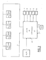
- Fig. 1 there is shown an exit with two leaves to be monitored.
- Each leaf has a BAP panic bar, SW contacts which change state when a thrust is applied to the leaf considered, and a BC control box.
- the control box contains electrical and electronic circuits which include connections 1 to the electromagnets for locking the BAP bars, connections 2 to the contacts SW, a connection 3 to the contacts SX of opening sensors and connections 4 to a UC control unit.
- a siren (or a flashing) SIR and a volumetric sensor CPT are schematically represented and connected respectively by links 5 and 6 to the control box.
- a BC control box could also be associated with a single leaf outlet.
- Fig. 2 shows the link 4 connecting the control boxes BC1 to BCm to the control unit UC. It appears that the link 4 forms a loop to which the control boxes of all the exits 1 to m are connected in derivation.
- a supply circuit ALIM providing a supply of for example 12 V DC
- a line 7 carrying a fire detection signal carrying a contact link 8 electric key CLE
- various auxiliary circuits such as a remote control circuit 9, a telephone transmitter 10, a parking meter-recorder 11, a speech synthesis circuit 12 and various interfaces 13.
- a control box BC comprises a microprocessor circuit MP, also called a microcontroller, input circuits including a call detection processing circuit DA and an opening detection processing circuit DO, output circuits including a CV locking control circuit, an interface circuit CI for exchanging information with loop 4 and various other input and output circuits, listed below.
- a microprocessor circuit MP also called a microcontroller
- input circuits including a call detection processing circuit DA and an opening detection processing circuit DO
- output circuits including a CV locking control circuit
- an interface circuit CI for exchanging information with loop 4 and various other input and output circuits, listed below.
- FIG. 1 we have also shown a power amplifier 14 whose output is connected to a light indicator 15, which for example turns yellow when at least one of the leaves has been opened, a power amplifier 16 whose output is connected to a sound emission or buzzer device 17, a power amplifier 18 whose output is connected to a light indicator 19 which turns red when the room is closed to the public (for the night), a power amplifier 20 whose output is connected to a light indicator 21 which turns green when the room is open to the public, an alarm circuit 22 connected to a line 23 transmitting an alarm signal, and an input amplifier 24 whose input is connected to link 4.
- a power amplifier 14 whose output is connected to a light indicator 15, which for example turns yellow when at least one of the leaves has been opened
- a power amplifier 16 whose output is connected to a sound emission or buzzer device 17
- a power amplifier 18 whose output is connected to a light indicator 19 which turns red when the room is closed to the public (for the night)
- a power amplifier 20 whose output is connected to a light indicator
- the line 1 is connected, on the one hand, to the output of the circuit CV by a diode D1 and, on the other hand, to the connection 4 by a diode D2, the diodes D1 and D2 having their cathodes connected together.
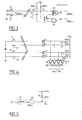
- FIG. 3 An example of a basic call detector is shown in Fig. 3. It includes an OR-exclusive gate P1 and a NAND-gate P2.
- the inputs E1 and E2 of the gate P1 are respectively connected to the working contact of a microswitch C1 and to the rest contact of a microswitch C2 whose common contacts are grounded.
- the microswitches C1 and C2 are contained in a BAP panic bar and normally change state when the panic bar is actuated.
- An input of the gate P2 is connected to the input E1 by means of an inverter Il and its other input is connected directly to the input E2.
- the inputs E1 and E2 are also connected to a voltage source of +12 V by two resistors R1 and R2 with a value of 600 ohms each, in order to be able to send a current of approximately 20 mA on the line wires.
- the outputs S1 and S2 of the doors P1 and P2 are connected to the logic circuit DA contained in the BC control box.
- the call detector of FIG. 3 is used to detect either an action on the bar or a fault. Indeed: - when C1 is open and C2 closed, the input E1 is at the high level and the input E2 at the low level. So the outputs S1 and S2 are both at the high level, which indicates that the bar is at rest, - when C1 and C2 are open, E1 and E2 are at the high level. So, there is a defect: either that there is a divergence between the microswitches, or that the line is cut, - when C1 is closed and C2 open, E1 goes to low level and E2 goes to high level.
- S1 is at the high level and S2 at the low level, which indicates that there is an action on the bar, that is to say a call, and - when C1 and C2 are closed, E1 and E2 are both at the high level.
- S1 is at the low level and S2 at the high level, which again indicates a fault, either a divergence between the microswitches, or a short circuit on the line.
- the call detector of FIG. 3 makes it possible to detect that a push has been exerted on the panic bar in order to obtain the opening of the monitored exit, that the two microswitches have a simultaneous operation or that the line which connects the bar to the box BC is neither cut nor short-circuited.
- the exit generally consists of two leaves, each fitted with a BAP panic bar, two sets of microswitches and two sets of electronic doors are provided.
- the output signals are combined, for example by OR circuits.
- the circuit of FIG. 4 shows a practical embodiment of a call detector for an exit with two leaves. It includes two sets of microswitches C1, C2 and C ⁇ 1, C' ⁇ 2, a source of +12 V, four resistors R1, R2 and R ⁇ 1, R ⁇ 2 of 600 ohms, with terminals E1, E2 and E ⁇ 1, E ⁇ 2. These terminals are connected to the inputs of four buffers or buffer amplifiers BF1, BF2 and BF ⁇ 1, BF ⁇ 2, the outputs of which are connected to the respective inputs of the logic circuit DA.
- the works ment of the detector of FIG. 4 is deduced in an obvious manner from that of the detector of FIG. 3.
- the logic functions of the electronic gates can be implemented in the DA circuit, which can also deal with contact bouncing phenomena so that no filtering is necessary.
- Fig. 5 shows the diagram of the preferred embodiment of an opening sensor according to the invention.
- a leaf opening sensor is, in general, constituted by a simple proximity contact which is a rest contact of which one terminal is grounded and the other connected, on the one hand, to a source voltage through a resistor and, on the other hand, a voltage comparator.
- Such an opening sensor does not make it possible to detect an opening when the contact has been maliciously short-circuited.
- the opening sensor consists of a contact C3 in series with a resistor R3, the non-common terminal of the contact C3 being grounded and the non-common terminal of R3 being connected, on the one hand, to a source of voltage of +12 V by a resistor R4 and, on the other hand, at the input E3 of a voltage comparator.
- Resistor R3 and contact C3 are mounted together in a tamper-evident block installed in the rebate of a leaf.
- the resistor R3 has a value of 200 ohms and the resistor R4 a value of 400 ohms.
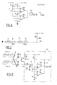
- the circuit of FIG. 6 shows an opening sensor circuit CO, which comprises a +12 V source to which the resistor R4 is connected, the terminal E3 of which, connected to the sensor, is also connected, on the one hand, to the inverting input of an operational amplifier OP1 and, on the other hand, at the non-inverting input of an amplifier OP2 operational designer.
- a voltage divider comprising three resistors R5, R6 and R7 in series, is mounted between the +12 V source and the ground.
- the values of the resistors R5, R6 and R7 are respectively 7 kilohms, 2 kilohms and 3 kilohms.
- the point common to R5 and R6 is connected to the non-inverting input of OP1 while the point common to R6 and R7 is connected to the inverting input of OP2.
- the outputs of the comparators OP1 and OP2 are connected to the two inputs of an AND gate P3, the output of which is connected to the circuit MP. It appears that the output of gate P3 is at high level as long as the voltage at E3 is between +3 V and +5 V. When it goes low, the MP circuit interprets the change of state and, depending on its own state, can trigger an alarm via circuit 22, Fig. 1.
- Fig. 7 is the diagram of a preferred example of mounting opening sensors, according to the invention, in the case where the opening detector is provided for an exit with two leaves each carrying a sensor according to FIG. 5.
- the two sensors C3, R3 and C ⁇ 3, R ⁇ 3, each belonging to a leaf, are connected in series, the free terminal of C3 being grounded and the free terminal of R ⁇ 3 being connected to a +12 V source by a resistance R8.
- the common point E4 to R ⁇ 3 and R8 is connected to a voltage comparator.
- Fig. 8 shows the complete diagram of the mounting of an opening detector in which the circuit of FIG. 7.
- Terminals a , b and c , d for connecting the two leaves have been shown.
- Terminal a is connected to ground and to C3.
- Terminal b is connected to R3 and to terminal c , on the one hand, by a strap W1 and, on the other hand, a resistor R9.
- Terminal c is connected to contact C ⁇ 3 and terminal d to resistor R ⁇ 3, on the one hand, and to the input of a voltage comparator, on the other.
- the resistor R9 is short-circuited by W1 and plays no role.
- terminal d and the input terminal E4 of a comparator which is identical to that of Fig.
- the control unit UC comprises a console provided with a switch, push-buttons and a set of circuits connected to the connection loop 4.
- the diagrams of these circuits are shown in Figs. 9 and 10.
- the connection 4 symbolically represented in FIG. 2, consists of a bundle of wires and transmits from the control unit UC to the control boxes BC: the power supply at the voltage of +12 V by the wires 25, the auxiliary supply to the voltage of +24 V by the wires 26, the ground potential at OV, a status command, which will be described below, by the wire 27 and various command commands, such as the 3 min time delay command , the pre-arming command, the rearming command, the acknowledgment command, by the wire 28.
- line 23 makes it possible to receive the alarm signals from the control boxes BC.
- the system of the invention is intended to operate in an "open” state, that is to say to protect people when the establishment is open to the public , and in "closed” state, when the establishment is closed, in particular to detect malicious intrusions.
- the control unit UC comprises the switch X1 with four positions: “closed”, “CDE1”, “CDE2” and “open”, which can be actuated by means of a key held by a supervisor.
- An input of switch X1, Fig. 9, is connected by a fuse F1 and a working contact kg1 to the source of +12 V.
- the outputs of the switch are connected to inputs of a generator of order 29 as well as to a timing circuit 30.
- An input E5 of circuit 29 is connected to the outputs of OPEN and CDE2 states of X1. Between the input E5 and line 28, two paths are provided: one comprising the working contact of a + 3MN key, the rest contact of a PREARM key and an R11 resistor, and the other comprising a rest contact of the + 3MN key, a working contact of the PREARM key and a resistor R12.
- An input E6 is connected to the state outputs CDE1 and CDE2 of X1. Between E6 and line 28, there is a working contact with a REARM button and a resistor R13.
- An input E7 is connected to the state outputs CDE1 and CDE2 of X1. Between E7 and line 28, there is a working contact with an ACQ key. Furthermore, in circuit 29, line 28 is connected to ground by a resistor R14.
- the values of resistors R11, R12, R13 and R14 are respectively 450, 150, 50 and 150 ohms.
- the timing circuit 30 is connected, firstly, to the CLOSED and CDE1 outputs of X1, secondly, to the CLE circuit by line 8 and, thirdly, to line 27 which transmits the CLOSED or OPEN information to the control boxes BC.
- the CLE circuit is used when the system is in the CLOSED state and the user enters the protected establishment.
- an order reception circuit CI is provided, FIG. 9, the input of which is connected to line 28.
- the circuit CI comprises four operational amplifiers OP3, OP4, OP5 and OP6, a voltage divider comprising, connected in series between the +12 V source and the ground, the resistors R15, R16, R17, R18 and R19 whose values are respectively 400, 600, 500, 300 and 600 ohms.
- the inverting inputs of the comparators OP3, OP4, OP5 and OP6 are respectively connected to the points common to R15 and R16, R16 and R17, R17 and R18, R18 and R19.
- the non-inverting inputs of the comparators OP3, OP4, OP5 and OP6 are respectively connected to line 28 by resistors R20, R21, R22 and R23 whose values are respectively 1470, 3600, 9600 and 11000 ohms. They are also connected to ground by capacitors CC2, CC3, CC4 and CC5, the values of which are 6.8, 6.8, 6.8 and 13.6 microfarads, respectively.
- the outputs S1 to S4 of the amplifiers OP3 to OP6 are connected to corresponding inputs of the MP circuit of the control box BC, Fig. 1.
- terminals E and S are provided for lines 25, 26, 27 and 28, which means that these lines are looped back. So cutting one wire leaves room for commands on the other wire.
- the purpose of the delay circuit 30 is to delay the energization of the line 15 when the owner of the key, which makes it possible to actuate the switch X1, puts the latter in the CLOSED position. This delay allows him to pass through the exit door provided with the CLE circuit without the alarm being triggered.
- the action on the CLE circuit triggers another time delay in the circuit 30 which has the effect of removing the voltage on line 27 for the time necessary for the user to put the switch X1 on. OPEN position.
- the UC control unit further includes connected in series between earth and the +12 V source, a general switch IG, a general cut-off relay KG and a fire loop 7.
- the relay KG is permanently supplied, unless line 7 opens or if the IG switch is pressed.
- the KG relay has two contacts, one kgl, in series with fuse F1, between source + 12V and line 25, the other kg2, in series with fuse F2, between source +24 V and line 26. Between fuse F1 and line 26, there is a diversion to alarm line 23, through a resistor R24.
- KA rest contacts kal of relays KAL, each provided in a control box BC. Then line 23 is looped to a relay KA, located in the control unit UC, and ground.
- the KA relay is energized when all the kal contacts are at rest and when the KG relay is at work. Otherwise, that is to say when an alarm must be triggered, it is de-energized.
- the relay KA has a contact kal, on the one hand, connected directly to the +12 V source and, on the other hand, to the supply circuit of a signaling circuit 31 comprising a siren and indicator lights. It also includes a contact ka2 connected, on the one hand, directly to the +12 V source and, on the other hand, to a terminal of switch X1, the CLOSED state of this terminal being connected to the excitation circuit d '' a bistable KB relay, grounded.
- the de-excitation circuit of the relay KB is connected to the input E7 of the circuit 29, FIG. 9, via the ACQ key contact.
- the KB relay is normally energized as soon as switch X1 is in the CLOSED state. It has a break contact mounted in the trip circuit of a telephone transmitter 10, also shown in FIG. 2. In the CLOSED state, when the relay KA drops out, the relay KB triggers the operation of the telephone transmitter 10.
- the state CDE1 allows the manager of the CPU unit to activate timer 30 or to acknowledge by the ACQ key. Thus it can, among other things, return the KB relay to its initial state.
- Fig. 12 is the diagram of the alarm circuit 22 in a control box BC.
- a wire 32 normally supplied, is connected, on the one hand, to a corresponding output of the MP circuit of the box and, on the other hand, to the input of a buffer amplifier or buffer AMP1, in CMOS technology.
- the output of the amplifier AMP1 is connected by a resistor R25, of 3.3 kilohms, to the base of a switching transistor TR1 whose emitter is grounded and the collector connected to line 25 by the winding of the KAL relay, protected by a diode DI1.
- Fig. 12 also shows the working contact kal of the relay mounted on the alarm line 23.
- the circuit MP when the circuit MP has received from the circuit DO information signaling an opening, it brings the wire 32 to the low level, which causes the relay KAL to drop and opens the contact kal, triggering the alarm by line 23.
- the power circuits 14, 16, 18 and 20 are preferably of the same type as that shown in FIG. 9 to trigger a local alarm including a siren and turn on (or off) indicator lights, which identify the outcome that is the subject of an event.
- Fig. 11 is the diagram of the circuit for controlling the lock or the locks of an outlet, this circuit being located in the control box BC of the outlet.
- the circuit of FIG. 11 includes a wire 33 connected to a corresponding terminal of the MP circuit and on which are mounted, in series, a resistor R26 of 1.5 kilohm and a capacitor CC6 of 22 nF whose terminal not connected to R26 is connected, of a on the other hand, at the input of an AMP2 amplifier and, on the other hand, to ground by an R27 resistance of 330 kilohms. Bypassed on resistance R27, is mounted a diode DI2 for restoring the DC component.
- the capacitor CC6 and the resistor R27 together constitute a branch circuit.
- the output of the amplifier AMP2 of CMOS technology is connected to the base of a switching transistor TR2 by, in series, a resistor R28 of 100 ohms, a direct diode DI3 and a resistor R29 of 3.3 kilohms.
- the point common to the diode DI3 and to the resistor R29 is connected to ground by a tantalum capacitor CC7 of 33 microfarads. Resistor R29 and capacitor CC7 together form a time constant bias circuit.
- the emitter of transistor TR2 is grounded and its collector is connected to the +12 V supply line 25 by the winding of a relay KVR, protected by a diode DI4.
- the relay KVR has a working contact kvr mounted between line 25 of +12 V and the anode of a diode DI5. Between line 27 and the cathode of diode DI5 is mounted a diode DI6 while between ground and the cathode of diode DI5 is mounted a diode DI7. The point common to the cathodes of the diodes DI5 to DI7 is connected to ground by the winding of the lock relay (s) VR of the leaves of the exit.
- the line 27 When the establishment is in the OPEN state, the line 27 is not supplied and the wire 33 normally receives from the circuit MP a rectangular alternating signal, for example with a period of 100 ms and a duty cycle 1.
- the derivative CC6, R27 then transmits a signal to the amplifier AMP2 which periodically charges the capacitor CC7. Therefore, the transistor TR2 remains supplied and the relay KVR is at work causing the excitation of the latch relays VR by kvr. If the MP circuit ceases to apply the rectangular signl to wire 33, the KVR relay falls back unlocking the issue.
- line 27 directly supplies the lock relays VR, by the diode DI6.
- Diode DI7 serves as a non-return diode.
- the MP circuit of each control box BC can, in practice, be a microcontroller of the 8051 type from the MCS51 family manufactured by the company INTEL.
- the internal structure of this microcontroller is well known to those skilled in the art.
- the output ports of the microcontroller are, for example, connected as follows: PO0 to wire 33, PO1 to wire 32, PO2 to a local alarm circuit comprising the SIR siren, PO3 to circuit 20 supplying the green light 21, lit when the establishment is in the OPEN state, PO4 to circuit 18 supplying the red light 19, on when the establishment is in the CLOSED state, PO5 on circuit 16 supplying the flashing light 17, and PO6 on circuit 14 supplying the orange indicator 15 of a crossing memory.
- the input ports of the MP microcontroller can be connected as follows: P10 to wire E1, Fig. 3, from a BAP bar, P11 to wire E2 of the same bar, P12 to wire E1 of the other BAPT bar and P13 to wire E2 of this other bar, P15 at the common output of the DO circuit, P16 at the output another CPT sensor, P20 at the output of the amplifier 24 connected to the wire 27, P21 to the wire S1, FIG. 9, P22 to wire S2, P23 to wire S3 and P24 to wire S4.
- the conventional power supply input VCC of the microcontroller is connected to line 25 through a regulator REG.
- An oscillator or SM "timer" allows the microcontroller to deliver the rectangular signal on wire 33.
- Fig. 13 is a flowchart illustrating the operation of the system when the establishment is in the OPEN state. It appears that an action on the BAP panic bar of an exit triggers the process. In the absence of an action by a supervisor, the lock opens after 8 seconds, leaving the free play of the panic bar. On the other hand, during these 8 seconds, a supervisor, after making sure that there is no panic, can extend the time delay by 3 minutes by pressing the + 3MN key on the console of the UC control unit . Without further maneuver, the lock opens after these 3 minutes. However, during these 3 minutes, he can, after dealing with the problem of the request to exit, pre-arm the lock by pressing the PREARM key on the console of the control unit.
- the lock opens then, after 4 seconds, re-locks.
- the supervisor can also reset the lock by pressing the REARM button on the control unit console.
- the microcontroller MP of the corresponding exit can send a signal to a crossing memory associated with 15 and which accounts for the openings. Note that unlocking a panic bar does not necessarily mean opening the corresponding exit.
- Fig. 14 is a standardized "GRAFCET" diagram which illustrates the operation of the system controller for the status of the OPEN establishment.
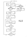
- Fig. 15 is a flowchart illustrating the operation of the system when the establishment is in the CLOSED state. It appears that the alarm is triggered by raising awareness of the rebate contacts of an exit. In this case, the crossing memory is armed at the same time as the alarm is triggered. The alarm creates for 30 seconds, for example, local actions, such as the operation of a siren or a flashing of indicators. The initial state is not restored until an authorized supervisor has pressed the ACQ acknowledgment key.
- Fig. 16 is a standardized "GRAFCET" diagram which illustrates the operation of the automaton for the state of the CLOSED establishment.
- a remote control transmitter which is provided with at least three push buttons.
- the first button is provided to obtain, in the UC unit, the opening of the IG switch which causes the general opening of the exits.
- the second is used to close a contact, not shown in FIG. 9, which short-circuits the contact of the + 3MN key.
- the third is used to close a contact, not shown in FIG. 9, which short-circuits the working contact of the PREARM key.
- line 23, FIG. 10 would be doubled by a transmission line which would be connected to the S-AS circuit of the control boxes BC1 to BCm.
- Each S-AS circuit is connected to a terminal PX of the MP circuit and is used to transmit a word in serial asynchronous mode which makes it possible to identify the box BC which has been activated, whereas line 23 does not allow this identification.
- the words sent by the boxes are received in the control unit which decodes them.
- a receiver is provided in the control unit to close or open these contacts, in parallel with the keys of the console of the control unit.
- the transmission between transmitters and receiver is established by known radio means, avoiding conflicts between the different remote control orders.
Abstract
Dans le système, les issues sont munies de barres de demande d'ouverture et de verrous. Le système comporte un poste central et des boîtes de contrôle. Chaque boîte de contrôle est associée à une issue et est reliée au poste central. L'actionnement d'une barre de demande d'ouverture commande l'envoi d'une information au poste central par la boîte de contrôle associée. Celle-ci déclenche une première temporisation To. Pendant celle-ci, l'ouverture de l'issue peut être condamnée pendant une seconde temporisation Tc. L'ouverture est autorisée à la fin de la première temporisation ou à la fin de la seconde temporisation. Une troisième temporisation Tp est prévue qui peut être déclenchée pendant la seconde temporisation Tc pour autoriser l'ouverture de l'issue considérée pendant la troisième temporisation Tp et reverrouiller l'issue considérée à la fin de la troisième temporisation Tp en annulant l'effet de la seconde temporisation Tc. Le système peut aussi fonctionner en mode anti-intrusion. Il est notamment applicable dans des magasins ou des établissements publics de surfaces moyennes.In the system, the exits are provided with opening request bars and latches. The system includes a central station and control boxes. Each control box is associated with an exit and is linked to the central station. The actuation of an opening request bar commands the sending of information to the central station by the associated control box. This triggers a first time delay To. During this, the opening of the exit can be condemned during a second time delay Tc. The opening is authorized at the end of the first time delay or at the end of the second time delay. A third time delay Tp is provided which can be triggered during the second time delay Tc to authorize the opening of the issue considered during the third time delay Tp and relock the issue considered at the end of the third time delay Tp by canceling the effect of the second time delay Tc. The system can also operate in anti-intrusion mode. It is particularly applicable in stores or public establishments of medium size.
Description
La présente invention concerne un système de contrôle et de surveillance d'issues dont l'utilisation est notamment prévue dans des magasins de vente de surfaces moyennes de l'ordre de 2500 m².The present invention relates to a system for controlling and monitoring exits, the use of which is in particular provided for in stores selling medium-sized areas of the order of 2500 m².
Les issues de secours des établissements ouverts au public sont munies d'organes d'ouverture qui doivent déverrouiller ces issues sous la poussée de personnes, pour une évacuation rapide du public en cas d'accident, tel qu'un incendie. Dans la pratique, pour éviter que ces issues ne soient utilisées frauduleusement, soit pour introduire des personnes dans le magasin, soit pour en sortir des marchandises, l'usager avait d'abord eu tendance à les condamner, ce qui était contraire à la réglementation; c'est pourquoi on en vient maintenant à installer des systèmes de contrôle et de surveillance de ces issues. Parmi ces systèmes, le plus simple consiste à prévoir que l'ouverture d'une issue de secours entraîne le déclenchement d'une alarme qui avertit un poste de gardiennage; ce système limite un peu l'utilisation frauduleuse, mais n'est pas totalement efficace. Un autre système, qui est décrit dans le document EP-A-O 156 752, comporte toujours un poste de gardiennage et, par issue de secours, un organe de déverrouillage, mais il prévoit, en plus, que l'actionnement de l'organe de verrouillage en vue de l'ouverture d'une issue de secours commande l'envoi d'une information au poste de gardiennage et le lancement d'une première temporisation To pendant laquelle le gardien, installé audit poste de gardiennage, peut condamner l'ouverture de l'issue considérée pendant une seconde temporisation Tc, l'ouverture de l'issue étant autorisée à la fin de la première temporisation To ou, en cas d'intervention du gardien, à la fin de la seconde temporisation Tc. Plus particulièrement, ce système est prévu pour être utilisé dans des établissements publics de très grande surface, dans lesquels certaines au moins des issues sont surveillées au moyen de caméras vidéo.The emergency exits of establishments open to the public are equipped with opening devices which must unlock these exits under the pressure of people, for rapid evacuation of the public in the event of an accident, such as a fire. In practice, to prevent these exits from being used fraudulently, either to bring people into the store or to get goods out of them, the user had first tended to condemn them, which was contrary to the regulations ; this is why we are now coming to install control and monitoring systems for these exits. Among these systems, the simplest consists in providing that the opening of an emergency exit causes the triggering of an alarm which warns a guard station; this system somewhat limits fraudulent use, but is not entirely effective. Another system, which is described in document EP-AO 156 752, still includes a guard station and, by emergency exit, an unlocking member, but it also provides that the actuation of the locking member locking in order to open an exit emergency orders the sending of information to the guard station and the launch of a first delay To during which the guard, installed at said guard post, can condemn the opening of the issue considered during a second delay Tc, the opening of the exit being authorized at the end of the first time delay To or, in the event of intervention by the guardian, at the end of the second time delay Tc. More particularly, this system is intended to be used in very large public establishments, in which at least some of the exits are monitored by video cameras.
Un objet de la présente invention consiste à prévoir un système perfectionné par rapport aux systèmes connus, et dans lequel le personnel de surveillance peut avoir plus d'initiative.An object of the present invention is to provide an improved system with respect to known systems, and in which the surveillance personnel can have more initiative.
Un autre objet de l'invention consiste à prévoir un système capable de servir de système d'alarme anti-intrusion quand l'espace à surveiller est fermé au public.Another object of the invention is to provide a system capable of serving as an anti-intrusion alarm system when the space to be monitored is closed to the public.
Suivant une caractéristique de l'invention, il est prévu un système comportant un poste central et des boîtes de contrôle, chaque boîte de contrôle étant associée à une issue et étant reliée au poste central, l'actionnement d'une barre de demande d'ouverture d'issue commandant l'envoi d'une information au poste central par l'intermédiaire de la boîte de contrôle associée, laquelle déclenche alors une première temporisation To pendant laquelle l'ouvertue de l'issue considérée peut être condamnée pendant une seconde temporisation Tc, l'ouverture de l'issue considérée étant autorisée à la fin de la première temporisation ou à la fin de la seconde temporisation, une troisième temporisation Tp pouvant être déclenchée pendant la seconde temporisation pour autoriser l'ouverture de l'issue considérée pendant la troisième temporisation Tp et reverrouiller l'issue considérée à la fin de la troisième temporisation Tp en annulant l'effet de la seconde temporisation Tc.According to a characteristic of the invention, there is provided a system comprising a central station and control boxes, each control box being associated with an outlet and being connected to the central station, the actuation of a request bar for opening of the exit ordering the sending of information to the central station by means of the associated control box, which then triggers a first time delay To during which the opening of the considered issue can be condemned during a second time delay Tc, the opening of the issue considered being authorized at the end of the first time delay or at the end of the second time delay, a third time delay Tp can be triggered during the second time delay to authorize the opening of the issue considered during the third time delay Tp and relock the issue considered at the end of the third time delay Tp by canceling the effect of the second time delay Tc.
Suivant une autre caractéristique, le poste central comprend des moyens de commande de verrouillage pour verrouiller et maintenir les issues verrouillées et des moyens de commutation pour actionner ces moyens de commande de verrouillage.According to another characteristic, the central station comprises locking control means for locking and keeping the exits locked and switching means for actuating these locking control means.
Suivant une autre caractéristique, les liaisons de commande entre le poste central et les boîtes de contrôle forment une boucle avec des dérivations vers chaque boîte de contrôle.According to another characteristic, the control links between the central station and the control boxes form a loop with branches to each control box.
Suivant une autre caractéristique, la liaison de signalisation de détection d'ouverture entre les boîtes de contrôle et le poste central est une ligne simple comportant en série des contacts de travail respectivement associés aux boîtes de contrôle, chaque contact étant fermé quand l'issue correspondante n'a pas été ouverte.According to another characteristic, the opening detection signaling link between the control boxes and the central station is a single line comprising in series working contacts respectively associated with the control boxes, each contact being closed when the corresponding issue has not been opened.
Les caractéristiques de l'invention mentionnées ci-dessus, ainsi que d'autres, apparaîtront plus clairement à la lecture de la description suivante d'un exemple de réalisation, ladite description étant faite en relation avec les dessins joints, parmi lesquels:
- la Fig. 1 est un schéma illustrant les moyens qui font partie du système de contrôle et de surveillance suivant l'invention et qui sont installés sur une issue et à proximité immédiate de celle-ci,
- la Fig. 2 est un diagramme du système de contrôle et de surveillance suivant l'invention et, en particulier, le block-diagramme du poste central du système,
- la Fig. 3 est un schéma d'un détecteur d'appel suivant l'invention,
- la Fig. 4 est un schéma d'une variante du détecteur de la Fig. 3,
- la Fig. 5 est le schéma d'un capteur d'ouverture connu,
- la Fig. 6 est le schéma d'un détecteur d'ouverture suivant l'invention, utilisant des capteurs montrés à la Fig. 5,
- la Fig. 7 est un schéma illustrant une variante de montage de capteurs de la Fig. 5,
- la Fig. 8 est le schéma d'un détecteur d'ouverture suivant l'invention,
- la Fig. 9 est un schéma d'une première partie du circuit de contrôle de l'unité de commande de la Fig. 2,
- la Fig. 10 est un schéma d'une seconde partie du circuit de contrôle de l'unité de commande de la Fig. 2,
- la Fig. 11 est un schéma du circuit de commande des verrous d'issue de la Fig. 2,
- la Fig. 12 est un schéma d'un circuit de sortie du microcontrôleur de la Fig. 1,
- la Fig. 13 est un organigramme illustrant le fonctionnement du système quand celui-ci est à l'état OUVERT,
- la Fig. 14 est un diagramme Grafcet illustrant le fonctionnement de l'automate du système en relation avec l'organigramme de la Fig. 13,
- la Fig. 15 est un organigramme illustrant le fonctionnement du système quand celui-ci est à l'état FERME, et
- la Fig. 16 est un diagramme Grafcet illustrant le fonctionnement de l'automate du système en relation avec l'organigramme de la Fig. 15.
- Fig. 1 is a diagram illustrating the means which form part of the control and monitoring system according to the invention and which are installed on an outlet and in the immediate vicinity thereof,
- Fig. 2 is a diagram of the control and monitoring system according to the invention and, in particular, the block diagram of the central station of the system,
- Fig. 3 is a diagram of a call detector according to the invention,
- Fig. 4 is a diagram of a variant of the detector of FIG. 3,
- Fig. 5 is the diagram of a known opening sensor,
- Fig. 6 is the diagram of an opening detector according to the invention, using the sensors shown in FIG. 5,
- Fig. 7 is a diagram illustrating a variant mounting of sensors of FIG. 5,
- Fig. 8 is the diagram of an opening detector according to the invention,
- Fig. 9 is a diagram of a first part of the control circuit of the control unit of FIG. 2,
- Fig. 10 is a diagram of a second part of the control circuit of the control unit of FIG. 2,
- Fig. 11 is a diagram of the control circuit for the exit locks of FIG. 2,
- Fig. 12 is a diagram of an output circuit of the microcontroller of FIG. 1,
- Fig. 13 is a flowchart illustrating the operation of the system when it is in the OPEN state,
- Fig. 14 is a Grafcet diagram illustrating the operation of the system controller in relation to the flow diagram of FIG. 13,
- Fig. 15 is a flowchart illustrating the operation of the system when it is in the CLOSED state, and
- Fig. 16 is a Grafcet diagram illustrating the operation of the system controller in relation to the flow diagram of FIG. 15.
A la Fig. 1, on a représenté une issue à deux vantaux à surveiller. Chaque vantail comporte une barre anti-panique BAP, des contacts SW qui changent d'état quand une poussée est appliquée au vantail considéré, et une boîte de contrôle BC. La boîte de contrôle contient des circuits électriques et électroniques qui comportent des liaisons 1 vers les électro-aimants de verrouillage des barres BAP, des liaisons 2 vers les contacts SW, une liaison 3 vers des contacts SX de capteurs d'ouverture et des liaisons 4 vers une unité de commande UC. De plus, une sirène (ou un clignotant) SIR et un capteur volumétrique CPT sont schématiquement représentés et respectivement reliés par des liaisons 5 et 6 à la boîte de commande. Bien entendu, une boîte de contrôle BC pourrait aussi être associée à une issue à vantail unique.In Fig. 1, there is shown an exit with two leaves to be monitored. Each leaf has a BAP panic bar, SW contacts which change state when a thrust is applied to the leaf considered, and a BC control box. The control box contains electrical and electronic circuits which include
La Fig. 2 montre la liaison 4 reliant les boîtes de contrôle BC1 à BCm à l'unité de commande UC. Il apparaît que la liaison 4 forme une boucle à laquelle sont reliées en dérivation les boîtes de contrôle de toutes les issues 1 à m.Fig. 2 shows the
A la Fig. 2, on a également représenté, reliés à l'unité de commande UC, un circuit d'alimentation ALIM fournissant une alimentation de par exemple 12 V en continu, une ligne 7 transportant un signal de détection d'incendie, une liaison 8 de contact de clé électrique CLE, et différents circuits auxiliaires, tels qu'un circuit de télécommande 9, un transmetteur téléphonique 10, un horodateur-enregistreur 11, un circuit de synthèse de la parole 12 et diverses interfaces 13.In Fig. 2, there is also shown, connected to the control unit UC, a supply circuit ALIM providing a supply of for example 12 V DC, a line 7 carrying a fire detection signal, a
Essentiellement, une boîte de contrôle BC comprend un circuit à microprocesseur MP, encore appelé microcontrôleur, des circuits d'entrée dont un circuit de traitement de détection d'appel DA et un circuit de traitement de détection d'ouverture DO, des circuits de sortie dont un circuit de commande de verrouillage CV, un circuit d'interface CI d'échange d'informations avec la boucle 4 et divers autres circuits d'entrée et de sortie, énumérés ci-après.Essentially, a control box BC comprises a microprocessor circuit MP, also called a microcontroller, input circuits including a call detection processing circuit DA and an opening detection processing circuit DO, output circuits including a CV locking control circuit, an interface circuit CI for exchanging information with
Ainsi à la Fig. 1, on a encore montré un amplificateur de puissance 14 dont la sortie est reliée à un indicateur lumineux 15, qui passe par exemple au jaune quand un des vantails, au moins, a été ouvert, un amplificateur de puissance 16 dont la sortie est reliée à un dispositif d'émission sonore ou buzzer 17, un amplificateur de puissance 18 dont la sortie est reliée à un indicateur lumineux 19 qui passe au rouge quand le local est fermé au public (pour la nuit), un amplificateur de puissance 20 dont la sortie est reliée à un indicateur lumineux 21 qui passe au vert quand le local et ouvert au public, un circuit d'alarme 22 relié à une ligne 23 transmettant un signal d'alarme, et un amplificateur d'entrée 24 dont l'entrée est reliée à la liaison 4.Thus in FIG. 1, we have also shown a
A la Fig. 1, la ligne 1 est reliée, d'une part, à la sortie du circuit CV par une diode D1 et, d'autre part, à la liaison 4 par une diode D2, les diodes D1 et D2 ayant leurs cathodes reliées ensemble.In Fig. 1, the
Un exemple de détecteur d'appel élémentaire est montré à la Fig. 3. Il comporte une porte OU-exclusif P1 et une porte NON-ET P2. Les entrées E1 et E2 de la porte P1 sont respectivement reliées au contact de travail d'un microcontact C1 et au contact de repos d'un microcontact C2 dont les contacts communs sont à la masse. Les microcontacts C1 et C2 sont contenus dans une barre anti-panique BAP et changent normalement d'état quand la barre anti-panique est actionnée. Une entrée de la porte P2 est reliée à l'entrée E1 par l'intermédiaire d'un inverseur Il et son autre entrée est reliée directement à l'entrée E2. Les entrées E1 et E2 sont également reliées à une source de tension de +12 V par deux résistances R1 et R2 d'une valeur de 600 ohms chacune, pour pouvoir envoyer un courant d'environ 20 mA sur les fils de ligne. Les sorties S1 et S2 des portes P1 et P2 sont reliées au circuit logique DA contenu dans la boîte de contrôle BC.An example of a basic call detector is shown in Fig. 3. It includes an OR-exclusive gate P1 and a NAND-gate P2. The inputs E1 and E2 of the gate P1 are respectively connected to the working contact of a microswitch C1 and to the rest contact of a microswitch C2 whose common contacts are grounded. The microswitches C1 and C2 are contained in a BAP panic bar and normally change state when the panic bar is actuated. An input of the gate P2 is connected to the input E1 by means of an inverter Il and its other input is connected directly to the input E2. The inputs E1 and E2 are also connected to a voltage source of +12 V by two resistors R1 and R2 with a value of 600 ohms each, in order to be able to send a current of approximately 20 mA on the line wires. The outputs S1 and S2 of the doors P1 and P2 are connected to the logic circuit DA contained in the BC control box.
Le détecteur d'appel de la Fig. 3 permet de détecter soit une action sur la barre, soit un défaut. En effet:
- quand C1 est ouvert et C2 fermé, l'entrée E1 est au niveau haut et l'entrée E2 au niveau bas. Donc les sorties S1 et S2 sont toutes deux au niveau haut, ce qui indique que la barre est au repos,
- quand C1 et C2 sont ouverts, E1 et E2 sont au niveau haut. Donc, il y a un défaut: soit qu'il y a divergence entre les microcontacts, soit que la ligne est coupée,
- quand C1 est fermé et C2 ouvert, E1 passe au niveau bas et E2 passe au niveau haut. Donc, S1 est au niveau haut et S2 au niveau bas, ce qui indique qu'il y a une action sur la barre, c'est-à-dire un appel, et
- quand C1 et C2 sont fermés, E1 et E2 sont toutes deux au niveau haut. S1 est au niveau bas et S2 au niveau haut, ce qui indique encore un défaut, soit une divergence entre les microcontacts, soit un court-circuit sur la ligne.The call detector of FIG. 3 is used to detect either an action on the bar or a fault. Indeed:
- when C1 is open and C2 closed, the input E1 is at the high level and the input E2 at the low level. So the outputs S1 and S2 are both at the high level, which indicates that the bar is at rest,
- when C1 and C2 are open, E1 and E2 are at the high level. So, there is a defect: either that there is a divergence between the microswitches, or that the line is cut,
- when C1 is closed and C2 open, E1 goes to low level and E2 goes to high level. So, S1 is at the high level and S2 at the low level, which indicates that there is an action on the bar, that is to say a call, and
- when C1 and C2 are closed, E1 and E2 are both at the high level. S1 is at the low level and S2 at the high level, which again indicates a fault, either a divergence between the microswitches, or a short circuit on the line.
Ainsi, le détecteur d'appel de la fig. 3 permet de détecter qu'une poussée a été exercée sur la barre anti-panique en vue d'obtenir l'ouverture de l'issue surveillée, que les deux microcontacts ont un fonctionnement simultané ou que la ligne qui relie la barre à la boîte BC n'est ni coupée, ni en court-circuit.Thus, the call detector of FIG. 3 makes it possible to detect that a push has been exerted on the panic bar in order to obtain the opening of the monitored exit, that the two microswitches have a simultaneous operation or that the line which connects the bar to the box BC is neither cut nor short-circuited.
En pratique, les fonctions des portes P1 et P2 et de l'inverseur Il sont remplies par des fonctions logiques du circuit de traitement DA auquel sont reliées les entrées E1 et E2.In practice, the functions of the doors P1 and P2 and of the inverter It are fulfilled by logic functions of the processing circuit DA to which the inputs E1 and E2 are connected.
Comme l'issue se compose généralement de deux vantaux munis chacun d'une barre anti-panique BAP, deux jeux de microcontacts et deux jeux de portes électroniques sont prévus. Les signaux de sortie sont réunis, par exemple par des circuits OU.As the exit generally consists of two leaves, each fitted with a BAP panic bar, two sets of microswitches and two sets of electronic doors are provided. The output signals are combined, for example by OR circuits.
Le circuit de la Fig. 4 montre une réalisation pratique de détecteur d'appel pour issue à deux vantaux. Il comprend deux jeux de microcontacts C1, C2 et Cʹ1, C'ʹ2, une source de +12 V, quatre résistances R1, R2 et Rʹ1, Rʹ2 de 600 ohms, avec des bornes E1, E2 et Eʹ1, Eʹ2. Ces bornes sont reliées aux entrées de quatre buffers ou amplificateurs tampons BF1, BF2 et BFʹ1, BFʹ2 dont les sorties sont reliées aux entrées respectives du circuit logique DA. Le fonctionne ment du détecteur de la Fig. 4 se déduit d'une manière évidente de celui du détecteur de la Fig. 3. Bien entendu, les fonctions logiques des portes électroniques peuvent être mises en oeuvre dans le circuit DA, lequel peut aussi traiter les phénomènes de rebonds des contacts si bien qu'aucun filtrage n'est nécessaire.The circuit of FIG. 4 shows a practical embodiment of a call detector for an exit with two leaves. It includes two sets of microswitches C1, C2 and Cʹ1, C'ʹ2, a source of +12 V, four resistors R1, R2 and Rʹ1, Rʹ2 of 600 ohms, with terminals E1, E2 and Eʹ1, Eʹ2. These terminals are connected to the inputs of four buffers or buffer amplifiers BF1, BF2 and BFʹ1, BFʹ2, the outputs of which are connected to the respective inputs of the logic circuit DA. The works ment of the detector of FIG. 4 is deduced in an obvious manner from that of the detector of FIG. 3. Of course, the logic functions of the electronic gates can be implemented in the DA circuit, which can also deal with contact bouncing phenomena so that no filtering is necessary.
La Fig. 5 montre le schéma de l'exemple de réalisation préféré d'un capteur d'ouverture suivant l'invention.Fig. 5 shows the diagram of the preferred embodiment of an opening sensor according to the invention.
On rappelle qu'un capteur d'ouverture de vantail est, en général, constitué par un simple contact de proximité qui est un contact de repos dont une borne est à la masse et l'autre reliée, d'une part, à une source de tension par l'intermédiaire d'une résistance et, d'autre part, à un comparateur de tension. Un tel capteur d'ouverture ne permet pas de détecter une ouverture quand le contact a été court-circuité par malveillance.It is recalled that a leaf opening sensor is, in general, constituted by a simple proximity contact which is a rest contact of which one terminal is grounded and the other connected, on the one hand, to a source voltage through a resistor and, on the other hand, a voltage comparator. Such an opening sensor does not make it possible to detect an opening when the contact has been maliciously short-circuited.
Dans l'exemple de réalisation de la Fig. 5, le capteur d'ouverture est constitué par un contact C3 en série avec une résistance R3, la borne non commune du contact C3 étant à la masse et la borne non commune de R3 étant reliée, d'une part, à une source de tension de +12 V par une résistance R4 et, d'autre part, à l'entrée E3 d'un comparateur de tension. La résistance R3 et le contact C3 sont montés ensemble dans un bloc inviolable installé dans la feuillure d'un vantail. A titre d'exemple, la résistance R3 à une valeur de 200 ohms et la résistance R4 une valeur de 400 ohms.In the exemplary embodiment of FIG. 5, the opening sensor consists of a contact C3 in series with a resistor R3, the non-common terminal of the contact C3 being grounded and the non-common terminal of R3 being connected, on the one hand, to a source of voltage of +12 V by a resistor R4 and, on the other hand, at the input E3 of a voltage comparator. Resistor R3 and contact C3 are mounted together in a tamper-evident block installed in the rebate of a leaf. For example, the resistor R3 has a value of 200 ohms and the resistor R4 a value of 400 ohms.
Quand le contact C3 est fermé au repos, la tension au point E3, commun à R3 et R4, a une valeur de +4 V. Quand le contact C3 est ouvert, la tension en E3 est de +12 V. Quand la ligne entre E3 et C3 est coupée, la tension en E3 est de 12 V. Quand le capteur est court-circuité, la tension en E3 est de 0 V. Il apparaît qu'il suffit de vérifier que la tension en E3 est comprise entre +3 V et +5 V pour savoir si le contact est fermé. En dehors de cette plage, il y a un événement à analyser.When the contact C3 is closed at rest, the voltage at point E3, common to R3 and R4, has a value of +4 V. When the contact C3 is open, the voltage at E3 is +12 V. When the line enters E3 and C3 is cut, the voltage in E3 is 12 V. When the sensor is short-circuited, the voltage in E3 is 0 V. It appears that it is enough to check that the voltage in E3 is between +3 V and +5 V to find out if the contact is closed. Outside this range, there is an event to analyze.
Le circuit de la Fig. 6 montre un circuit détecteur d'ouverture CO, lequel comprend une source de +12 V à laquelle est reliée la résistance R4 dont la borne E3, reliée au capteur, est également reliée, d'une part, à l'entrée inverseuse d'un amplificateur opérationnel OP1 et, d'autre part, à l'entrée non inverseuse d'un amplifi cateur opérationnel OP2. Un diviseur de tension, comprenant trois résistances R5, R6 et R7 en série, est monté entre la source de +12 V et la masse. Les valeurs des résistances R5, R6 et R7 sont respectivement de 7 kilohms, 2 kilohms et 3 kilohms. Le point commun à R5 et R6 est relié à l'entrée non inverseuse de OP1 tandis que le point commun à R6 et R7 est relié à l'entrée inverseuse de OP2. Les sorties des comparateurs OP1 et OP2 sont reliées aux deux entrées d'une porte ET P3 dont la sortie est reliée au circuit MP. Il apparaît que la sortie de la porte P3 est au niveau haut tant que la tension en E3 est comprise entre +3 V et +5 V. Quand elle passe au niveau bas, le circuit MP interprète le changement d'état et, selon son propre état, peut déclencher une alarme par le circuit 22, Fig. 1.The circuit of FIG. 6 shows an opening sensor circuit CO, which comprises a +12 V source to which the resistor R4 is connected, the terminal E3 of which, connected to the sensor, is also connected, on the one hand, to the inverting input of an operational amplifier OP1 and, on the other hand, at the non-inverting input of an amplifier OP2 operational designer. A voltage divider, comprising three resistors R5, R6 and R7 in series, is mounted between the +12 V source and the ground. The values of the resistors R5, R6 and R7 are respectively 7 kilohms, 2 kilohms and 3 kilohms. The point common to R5 and R6 is connected to the non-inverting input of OP1 while the point common to R6 and R7 is connected to the inverting input of OP2. The outputs of the comparators OP1 and OP2 are connected to the two inputs of an AND gate P3, the output of which is connected to the circuit MP. It appears that the output of gate P3 is at high level as long as the voltage at E3 is between +3 V and +5 V. When it goes low, the MP circuit interprets the change of state and, depending on its own state, can trigger an alarm via
La Fig. 7 est le schéma d'un exemple préféré de montage de capteurs d'ouverture, suivant l'invention, dans le cas où le détecteur d'ouverture est prévu pour une issue à deux vantaux portant chacun un capteur suivant la Fig. 5. Les deux capteurs C3, R3 et Cʹ3, Rʹ3, appartenant chacun à un vantail, sont montés en série, la borne libre de C3 étant à la masse et la borne libre de Rʹ3 étant reliée à une source de +12 V par une résistance R8. Le point commun E4 à Rʹ3 et R8 ets relié à un comparateur de tension. Dans cet exemple de montage, R3 = Rʹ3 = 200 ohms et R8 = 800 ohms. Quand les capteurs sont fermés et que la ligne entre R8 et Rʹ3 est à l'état normal, la tension en E4 est de +4 V. Quand la ligne entre E4 et Rʹ3 est ouverte ou que l'un des capteurs est ouvert, la tension en E4 est de +12 V. Quand un des capteurs est court-circuité, la tension en E4 est de +2,4 V. Quand les deux capteurs ou la ligne sont court-circuités, la tension en E4 est de 0 V.Fig. 7 is the diagram of a preferred example of mounting opening sensors, according to the invention, in the case where the opening detector is provided for an exit with two leaves each carrying a sensor according to FIG. 5. The two sensors C3, R3 and Cʹ3, Rʹ3, each belonging to a leaf, are connected in series, the free terminal of C3 being grounded and the free terminal of Rʹ3 being connected to a +12 V source by a resistance R8. The common point E4 to Rʹ3 and R8 is connected to a voltage comparator. In this mounting example, R3 = Rʹ3 = 200 ohms and R8 = 800 ohms. When the sensors are closed and the line between R8 and Rʹ3 is in the normal state, the voltage at E4 is +4 V. When the line between E4 and Rʹ3 is open or one of the sensors is open, the voltage in E4 is +12 V. When one of the sensors is short-circuited, the voltage in E4 is +2.4 V. When the two sensors or the line are short-circuited, the voltage in E4 is 0 V .
La Fig. 8 montre le schéma complet du montage d'un détecteur d'ouverture dans lequel on utilise le circuit de la Fig. 7. On a fait figurer les bornes a, b et c, d de raccordement des deux vantaux. La borne a est reliée à la masse et à C3. La borne b est reliée à R3 et à la borne c, d'une part, par un strap W1 et, d'autre part, une résistance R9. La borne c est reliée au contact Cʹ3 et la borne d à la résistance Rʹ3, d'une part, et à l'entrée d'un comparateur de tension, d'autre part. Dans ce montage, la résistance R9 est court-circuitée par W1 et ne joue aucun rôle. De plus, entre la borne d et la borne d'entrée E4 d'un comparateur, qui est identique à celui de la Fig. 6, est prévu un filtre constitué par une résistance R10 de 10 kilohms en série et un condensateur CC1 de 10 microfarads en parallèle. On pourra vérifier que ce circuit fonctionne dans les mêmes conditions que celui de la Fig. 7.Fig. 8 shows the complete diagram of the mounting of an opening detector in which the circuit of FIG. 7. The terminals a , b and c , d for connecting the two leaves have been shown. Terminal a is connected to ground and to C3. Terminal b is connected to R3 and to terminal c , on the one hand, by a strap W1 and, on the other hand, a resistor R9. Terminal c is connected to contact Cʹ3 and terminal d to resistor Rʹ3, on the one hand, and to the input of a voltage comparator, on the other. In this arrangement, the resistor R9 is short-circuited by W1 and plays no role. In addition, between terminal d and the input terminal E4 of a comparator, which is identical to that of Fig. 6, there is provided a filter constituted by a resistor R10 of 10 kilohms in series and a capacitor CC1 of 10 microfarads in parallel. It will be possible to verify that this circuit operates under the same conditions as that of FIG. 7.
Dans le cas où l'on veut utiliser ce circuit avec un seul vantail, on déplace le strap W1 entre les bornes c et d, la résistance R9 de 200 ohms entrant en circuit pour ne pas perturber le fonctionnement du comparateur.If you want to use this circuit with a single leaf, move the strap W1 between terminals c and d , the resistor R9 of 200 ohms entering the circuit so as not to disturb the operation of the comparator.
La partie du circuit de la Fig. 8 qui se trouve à droite de la borne d se trouve, en réalité, dans le circuit DO de la Fig. 1.The part of the circuit of FIG. 8 which is to the right of terminal d is, in reality, in the circuit DO of FIG. 1.
L'unité de commande UC comprend un pupître pourvu d'un commutateur, de boutons-poussoirs et d'un ensemble de circuits relié à la boucle de liaison 4. Les schémas de ces circuits sont représentés aux Figs. 9 et 10. En pratique, la liaison 4, symboliquement représentée à la Fig. 2, se compose d'un faisceau de fils et transmet à partir de l'unité de commande UC vers les boîtes de contrôle BC: l'alimentation de puissance à la tension de +12 V par les fils 25, l'alimentation auxiliaire à la tension de +24 V par les fils 26, le potentiel de masse à O V, une commande d'état, qui sera décrite dans la suite, par le fil 27 et divers ordres de commande, tels que la commande de temporisation de 3 mn, la commande de préarmement, la commande de réarmement, la commande d'acquittement, par le fil 28. De plus, la ligne 23 permet de recevoi les signaux d'alarme des boîtes de contrôle BC.The control unit UC comprises a console provided with a switch, push-buttons and a set of circuits connected to the
Comme on l'a mentionné dans le préambule de la présente description, le système de l'invention est prévu pour fonctionner, en état "ouvert", c'est-à-dire pour protéger les personnes quand l'établissement est ouvert au public, et en état "fermé", quand l'établissement est fermé, pour notamment détecter les intrusions malveillantes. A cet effet, l'unité de commande UC comprend le commutateur X1 à quatre positions: "fermé", "CDE1", "CDE2" et "ouvert", qui peut être actionné au moyen d'une clé détenue par un surveillant.As mentioned in the preamble to this description, the system of the invention is intended to operate in an "open" state, that is to say to protect people when the establishment is open to the public , and in "closed" state, when the establishment is closed, in particular to detect malicious intrusions. To this end, the control unit UC comprises the switch X1 with four positions: "closed", "CDE1", "CDE2" and "open", which can be actuated by means of a key held by a supervisor.
Une entrée du commutateur X1, Fig. 9, est reliée par un fusible F1 et un contact de travail kg1 à la source de +12 V. Les sorties du commutateur sont reliées à des entrées d'un générateur d'ordre 29 ainsi qu'à un circuit de temporisation 30.An input of switch X1, Fig. 9, is connected by a fuse F1 and a working contact kg1 to the source of +12 V. The outputs of the switch are connected to inputs of a generator of
Une entrée E5 du circuit 29 est reliée aux sorties d'états OUVERT et CDE2 de X1. Entre l'entrée E5 et la ligne 28, sont prévus deux trajets: l'un comprenant le contact de travail d'une touche +3MN, le contact de repos d'une touche PREARM et une résistance R11, et l'autre comprenant un contact de repos de la touche +3MN, un contact de travail de la touche PREARM et une résistance R12. Une entrée E6 est reliée aux sorties d'états CDE1 et CDE2 de X1. Entre E6 et la ligne 28, est prévu un contact de travail d'une touche REARM et une résistance R13. Un entrée E7 est reliée aux sorties d'états CDE1 et CDE2 de X1. Entre E7 et la ligne 28, est prévu un contact de travail d'une touche ACQ. Par ailleurs, dans le circuit 29, la ligne 28 est reliée à la masse par une résistance R14. Les valeurs des résistances R11, R12, R13 et R14 sont respectivement de 450, 150, 50 et 150 ohms.An input E5 of
Le circuit de temporisation 30 est relié, premièrement, aux sorties FERME et CDE1 de X1, deuxièmement, au circuit CLE par la ligne 8 et, troisièmement, à la ligne 27 qui transmet aux boîtes de contrôle BC l'information FERME ou OUVERT. En pratique, le circuit CLE est utilisé quand le système est à l'état FERME et que l'usager entre dans l'établissement protégé.The
Dans chaque boîte de contrôle BC, est prévu un circuit de réception d'ordre CI, Fig. 9, dont l'entrée est reliée à la ligne 28. Le circuit CI comprend quatre amplificateurs opérationnels OP3, OP4, OP5 et OP6, un diviseur de tension comprenant, montées en série entre la source de +12 V et la masse, les résistances R15, R16, R17, R18 et R19 dont les valeurs sont respectivement de 400, 600, 500, 300 et 600 ohms. Les entrées inverseuses des comparateurs OP3, OP4, OP5 et OP6 sont respectivement reliées aux points communs à R15 et R16, R16 et R17, R17 et R18, R18 et R19. Les entrées non inverseuses des comparateurs OP3, OP4, OP5 et OP6 sont respectivement reliées à la ligne 28 par des résistances R20, R21, R22 et R23 dont les valeurs sont respectivement de 1470, 3600, 9600 et 11000 ohms. Elles sont également reliées à la masse par des condensateurs CC2, CC3, CC4 et CC5 dont les valeurs sont respectivmeent de 6,8, 6,8, 6,8 et 13,6 microfarads. Les sorties S1 à S4 des amplificateurs OP3 à OP6 sont reliées à des entrées correspondantes du circuit MP de la boîte de contrôle BC, Fig. 1.In each control box BC, an order reception circuit CI is provided, FIG. 9, the input of which is connected to
Quand il n'y a aucun signal à transmettre par la ligne 28, c'est-à-dire qu' aucune des touches +3MN, PREARM, REARM, ACQ n'est enfoncée, la tension sur la ligne est nulle. Etant donné les polarisations des amplificateurs OP3 à OP6, toutes les sorties S1 à S4 restent au niveau bas, le seuil de OP3 étant de +3 V. Quand la touche +3MN est enfoncée, une tension de +3,5 V est appliquée à la ligne 28 et seule la sortie S1 passe au niveau haut, car le seuil de OP4 est de +4,5 V. Quand la touche PREARM est enfoncée, une tension de +5,5 V est appliquée à la ligne 28 et les sorties S1 et S2 passent au niveau haut car le seuil de OP4 est de +7 V. Quand la touche REARM est enfoncée une tension de +8 V est appliquée à la ligne 28 et les sorties S1, S2 et S3 passent au niveau haut, car le seuil de OP6 est de +10 V. Quand la touche ACQ est enfoncée, une tension de +12 V est appliquée à la ligne 28 et les quatre sortie S1 à S4 passent à l'état haut. Ainsi, les combinaisons logiques des niveaux des sorties S1 à S4 permettent de décoder la nature de la commande. En pratique, les sorties S1 à S4 sont reliées à circuit MP qui exécute le décodage et en tire les actions à exécuter sur l'issue.When there is no signal to be transmitted via
On notera qu'un verrouillage électrique interdit de transmettre à la fois les commandes +3MN et PREARM. Un verrouillage du même genre n'est pas prévu pour les touches REARM et ACQ, car ces touches ne sont, en principe, qu'à la disposition du détenteur de la clé, c'est-à-dire un cadre de l'établissement.Note that an electrical lock prohibits the transmission of both the 3MN and PREARM commands. A similar lock is not provided for the REARM and ACQ keys, because these keys are, in principle, only available to the key holder, that is to say a manager of the establishment .
Il faut également noter que les combinaisons, deux à deux, des résistances R20 à R23 et des condensateurs CC2 à CC5 établissent, en plus du filtrage, des constantes de temps croissantes de manière que quelle que soit la commande, le comparateur dont le seuil est juste au-dessous de la tension transmise bascule le premier. Il en résulte qu'il ne peut y avoir de fausse interprétation dans le circuit MP que l'on programme pour scruter de S4 vers S1.It should also be noted that the combinations, two by two, of the resistors R20 to R23 and the capacitors CC2 to CC5 establish, in addition to the filtering, increasing time constants so that whatever the command, the comparator whose threshold is just below the transmitted voltage switches first. It follows that there can be no false interpretation in the MP circuit that is programmed to scan from S4 to S1.
Si la ligne 28 est coupée, aucune commande n'étant transmise, l'issue sera déverrouillée 8 secondes après la première action sur une barre anti-panique de cette issue.If
Par ailleurs, à la Fig. 9, il apparaît que des bornes E et S sont prévues pour les lignes 25, 26, 27 et 28, ce qui veut dire que ces lignes sont rebouclées. Donc, la coupure d'un seul fil laisse le passage pour les commandes sur l'autre fil.Furthermore, in FIG. 9, it appears that terminals E and S are provided for
Le circuit de temporisation 30 a pour objet de différer la mise sous tension de la ligne 15 quand le possesseur de la clé, qui permet d'actionner le commutateur X1, met celui-ci en position FERME. Cette temporisation lui permet de franchir la porte de sortie pourvu du circuit CLE sans que l'alarme soit déclenchée. A l'ouverture de l'établissment, l'action sur le circuit CLE déclenche une autre temporisation dans le circuit 30 qui a pour effet de supprimer la tension sur la ligne 27 pendant le temps nécessaire à l'utilisateur pour mettre le commutateur X1 en position OUVERT.The purpose of the
L'unité de commande UC, Fig. 9, comprend encore monté en série entre la masse et la source de +12 V, un interrupteur général IG, un relais de coupure générale KG et une boucle d'incendie 7. Le relais KG est alimenté en permanence, sauf si la ligne 7 s'ouvre ou si on actionne l'interrupteur IG. Le relais KG a deux contacts, l'un kgl, en série avec le fusible F1, entre la source +12V et la ligne 25, l'autre kg2, en série avec un fusible F2, entre la source +24 V et la ligne 26. Entre le fusible F1 et la ligne 26, il est prévu une dérivation vers la ligne d'alarme 23, à travers une résistance R24.The UC control unit, Fig. 9, further includes connected in series between earth and the +12 V source, a general switch IG, a general cut-off relay KG and a fire loop 7. The relay KG is permanently supplied, unless line 7 opens or if the IG switch is pressed. The KG relay has two contacts, one kgl, in series with fuse F1, between source + 12V and
A la Fig. 10, sur la ligne d'alarme 23 sont montés, en série, des contacts de repos kal des relais KAL, chacun prévu dans une boîte de contrôle BC. Puis la ligne 23 est bouclée vers un relais KA, situé dans l'unité de commande UC, et la masse. Le relais KA est excité quand tous les contacts kal sont au repos et quand le relais KG est au travail. Dans le cas contraire, c'est-à-dire quand il faut déclencher une alarme, il est désexcité.In Fig. 10, on the
Le relais KA a un contact kal, d'une part, relié directement à la source de +12 V et, d'autre part, au circuit d'alimentation d'un circuit de signalisation 31 comprenant une sirène et des voyants lumineux. Il comporte aussi un contact ka2 relié, d'une part, directement à la source de +12 V et, d'autre part, à une borne du commutateur X1, l'état FERME de cette borne étant relié au circuit d'excitation d'un relais bistable KB, à la masse. Le circuit de desexcitation du relais KB est relié à l'entrée E7 du circuit 29, Fig. 9, par l'intermédiaire du contact de touche ACQ. Le relais KB est, normalement excité dès que le commutateur X1 est à l'état FERME. Il a un contact de repos monté dans le circuit de déclenchement d'un transmetteur téléphonique 10, également montré à la fig. 2. A l'état FERME, quand le relais KA retombe, le relais KB déclenche le fonctionnement du transmetteur téléphonique 10.The relay KA has a contact kal, on the one hand, connected directly to the +12 V source and, on the other hand, to the supply circuit of a
A la Fig. 9, l'état CDE1 permet au responsable de l'unité UC d'actionner la temporisation 30 ou de procéder à un acquittement par la touche ACQ. Ainsi il peut, entre autres, ramener le relais KB à son état initial.In Fig. 9, the state CDE1 allows the manager of the CPU unit to activate
La Fig. 12 est le schéma du circuit d'alarme 22 dans un boîte de contrôle BC. Un fil 32, normalement alimenté, est relié, d'une part, à une sortie correspondante du circuit MP de la boîte et, d'autre part, à l'entrée d'un amplificateur tampon ou buffer AMP1, en technologie CMOS. La sortie de l'amplificateur AMP1 est reliée par une résistance R25, de 3,3 kilohms, à la base d'un transistor de commutation TR1 dont l'émetteur est à la masse et le collecteur relié à la ligne 25 par l'enroulement du relais KAL, protégé par une diode DI1. La Fig. 12 montre également le contact de travail kal du relais monté sur la ligne d'alarme 23.Fig. 12 is the diagram of the
En fonctionnement, quand le circuit MP a reçu du circuit DO une information signalant une ouverture, il fait passer le fil 32 au niveau bas, ce qui fait retomber le relais KAL et ouvre le contact kal, déclenchant l'alarme par la ligne 23.In operation, when the circuit MP has received from the circuit DO information signaling an opening, it brings the
Les circuits de puissance 14, 16, 18 et 20 sont, de préférence, du même type que celui qui est montré à la Fig. 9 pour déclenche une alarme locale comprenant une sirène et allumer (ou éteindre) des voyants lumineux, qui permettent d'identifier l'issue qui est l'objet d'un événement.The
La Fig. 11 est le schéma du circuit CV de commande du verrou ou des verrous d'une issue, ce circuit étant situé dans la boîte de contrôle BC de l'issue.Fig. 11 is the diagram of the circuit for controlling the lock or the locks of an outlet, this circuit being located in the control box BC of the outlet.
Le circuit de la Fig. 11 comprend un fil 33 reliée à une borne correspondante du circuit MP et sur lequel sont montés, en série, une résistance R26 de 1,5 kilohm et un condensateur CC6 de 22 nF dont la borne non reliée à R26 est reliée, d'une part, à l'entrée d'un amplificateur AMP2 et, d'autre part, à la masse par une résistance R27 de 330 kilohms. En dérivation sur la résistance R27, est montée une diode DI2 de restauration de la composante continue. Le condensateur CC6 et la résistance R27 constituent ensemble un circuit dérivateur. La sortie de l'amplificateur AMP2 de technologie CMOS est reliée à la base d'un transistor de commutation TR2 par, en série, une résistance R28 de 100 ohms, une diode directe DI3 et une résistance R29 de 3,3 kilohms. Le point commun à la diode DI3 et à la résistance R29 est reliée à la masse par un condensateur au tantale CC7 de 33 microfarads. La résistance R29 et le condensateur CC7 constituent ensemble un circuit de polarisation à constante de temps. L'émetteur du transistor TR2 est à la masse et son collecteur est reliée à la ligne 25 d'alimentation en +12 V par l'enroulement d'un relais KVR, protégé par une diode DI4.The circuit of FIG. 11 includes a
Le relais KVR a un contact de travail kvr monté entre la ligne 25 de +12 V et l'anode d'une diode DI5. Entre la ligne 27 et la cathode de la diode DI5 est montée une diode DI6 tandis qu'entre la masse et la cathode de la diode DI5 est montée une diode DI7. Le point commun aux cathodes des diodes DI5 à DI7 est reliée à la masse par l'enroulement du ou des relais de verrous VR des vantaux de l'issue.The relay KVR has a working contact kvr mounted between
Quand l'établissement est à l'état OUVERT, la ligne 27 n'est pas alimentée et le fil 33 reçoit normalement du circuit MP un signal alternatif rectangulaire, par exemple de période 100 ms et de rapport cyclique 1. Le dérivateur CC6, R27 transmet alors un signal à l'amplificateur AMP2 qui charge périodiquement le condensateur CC7. Donc, le transistor TR2 reste alimenté et le relais KVR est au travail entraînant l'excitation des relais de verrou VR par kvr. Si le circuit MP cesse d'appliquer le signl rectangulaire au fil 33, le relais KVR retombe en déverrouillant l'issue.When the establishment is in the OPEN state, the
Par ailleurs, quand l'établissement est à l'état FERME, la ligne 27 alimente directement les relais de verrou VR, par la diode DI6. La diode DI7 sert de diode anti-retour.Furthermore, when the establishment is in the CLOSED state,
Le circuit MP de chaque boîte de contrôle BC peut, en pratique, être un microcontrôleur du type 8051 de la famille MCS51 fabriquée par la Société INTEL. La structure interne de ce microcontrôleur est bien connue de l'homme de métier. Les ports de sortie du microcontrôleur sont, par exemple, reliés de la manière suivante: PO0 au fil 33, PO1 au fil 32, PO2 à un circuit d'alarme locale comportant la sirène SIR, PO3 au circuit 20 alimentant le voyant vert 21, allumé quand l'établissement est à l'état OUVERT, PO4 au circuit 18 alimentant le voyant rouge 19, allumé quand l'établissment est à l'état FERME, PO5 au circuit 16 alimentant le clignotant 17, et PO6 au circuit 14 alimentant le voyant orange 15 d'une mémoire de franchissement.The MP circuit of each control box BC can, in practice, be a microcontroller of the 8051 type from the MCS51 family manufactured by the company INTEL. The internal structure of this microcontroller is well known to those skilled in the art. The output ports of the microcontroller are, for example, connected as follows: PO0 to wire 33, PO1 to wire 32, PO2 to a local alarm circuit comprising the SIR siren, PO3 to
Les ports d'entrée du microcontrôleur MP peuvent être reliés comme suit: P10 au fil E1, Fig. 3, d'une barre BAP, P11 au fil E2 de la même barre, P12 au fil E1 de l'autre barre BAPT et P13 au fil E2 de cette autre barre, P15 à la sortie commune du circuit DO, P16 à la sortie d'un autre capteur CPT, P20 à la sortie de l'amplificateur 24 relié au fil 27, P21 au fil S1, Fig. 9, P22 au fil S2, P23 au fil S3 et P24 au fil S4. L'entrée d'alimentation classique VCC du microcontrôleur est reliée à la ligne 25 à travers un régulateur REG. Un oscillateur ou SM "timer" permet au microcontrôleur de délivrer le signal recangulaire sur le fil 33.The input ports of the MP microcontroller can be connected as follows: P10 to wire E1, Fig. 3, from a BAP bar, P11 to wire E2 of the same bar, P12 to wire E1 of the other BAPT bar and P13 to wire E2 of this other bar, P15 at the common output of the DO circuit, P16 at the output another CPT sensor, P20 at the output of the
La Fig. 13 est un organigramme illustrant le fonctionnement du système quand l'établissement est à l'état OUVERT. Il apparaît qu'une action sur la barre anti-panique BAP d'une issue déclenche le processus. En l'absence d'une action d'un surveillant, le verrou s'ouvre au bout de 8 secondes, laissant le libre jeu de la barre antipanique. Par contre, pendant ces 8 secondes, un surveillant, après s'être assuré qu'il n'y a pas de panique, peut prolonger la temporisation de 3 minutes en appuyant sur la touche +3MN du pupître de l'unité de commande UC. Sans autre manoeuvre, le verrou s'ouvre alors au bout de ces 3 minutes. Toutefois, pendant ces 3 minutes, il peut, après avoir traité le problème de la demande de sortie, préarmer le verrou en appuyant sur la touche PREARM du pupître de l'unité de commande. Pour des raisons de sécurité, le verrou s'ouvre alors, puis au bout de 4 secondes, se rebloque. Le surveillant peut également réarmer le verrou en appuyant sur la touche REARM du pupître de l'unité de commande. Chaque fois que l'issue a été ouverte, le microcontrôleur MP de l'issue correspondante peut envoyer un signal à une mémoire de franchissement associée à 15 et qui comptabilise les ouvertures. A noter que le déverrouillage d'une barre-antipanique n'implique pas obligatoirement l'ouverture de l'issue correspondante.Fig. 13 is a flowchart illustrating the operation of the system when the establishment is in the OPEN state. It appears that an action on the BAP panic bar of an exit triggers the process. In the absence of an action by a supervisor, the lock opens after 8 seconds, leaving the free play of the panic bar. On the other hand, during these 8 seconds, a supervisor, after making sure that there is no panic, can extend the time delay by 3 minutes by pressing the + 3MN key on the console of the UC control unit . Without further maneuver, the lock opens after these 3 minutes. However, during these 3 minutes, he can, after dealing with the problem of the request to exit, pre-arm the lock by pressing the PREARM key on the console of the control unit. For security reasons, the lock opens then, after 4 seconds, re-locks. The supervisor can also reset the lock by pressing the REARM button on the control unit console. Each time that the exit has been opened, the microcontroller MP of the corresponding exit can send a signal to a crossing memory associated with 15 and which accounts for the openings. Note that unlocking a panic bar does not necessarily mean opening the corresponding exit.
La Fig. 14 est un diagramme normalisé "GRAFCET" qui illustre le fonctionnement de l'automate du système pour l'état de l'établissement OUVERT.Fig. 14 is a standardized "GRAFCET" diagram which illustrates the operation of the system controller for the status of the OPEN establishment.
La Fig. 15 est un organigramme illustrant le fonctionnement du système quand l'établissement est à l'état FERME. Il apparaît que l'alarme est déclenchée par la sensibilisation des contacts de feuillure d'une issue. Dans ce cas, il y a armement de la mémoire de franchissement en même temps que le déclenchement de l'alarme. L'alarme crée durant 30 secondes, par exemple, des actions locales, telles que le fonctionnement d'une sirène ou un clignotement de voyants. L'état initial n'est rétabli que quand un surveillant habilité a appuyé sur la touche d'acquittement ACQ.Fig. 15 is a flowchart illustrating the operation of the system when the establishment is in the CLOSED state. It appears that the alarm is triggered by raising awareness of the rebate contacts of an exit. In this case, the crossing memory is armed at the same time as the alarm is triggered. The alarm creates for 30 seconds, for example, local actions, such as the operation of a siren or a flashing of indicators. The initial state is not restored until an authorized supervisor has pressed the ACQ acknowledgment key.
La Fig. 16 est un diagramme normalisé "GRAFCET" qui illustre le fonctionnement de l'automate pour l'état de l'établissement FERME.Fig. 16 is a standardized "GRAFCET" diagram which illustrates the operation of the automaton for the state of the CLOSED establishment.
En pratique, il est également possible de doter des surveillants hors du champ de vision du surveillant principal affecté au pupître, d'un émetteur de télécommande, lequel est muni d'au moins trois boutons-poussoirs. Le premier bouton est prévu pour obtenir, dans l'unité UC, l'ouverture de l'interrupteur IG qui provoque l'ouverture générale des issues. Le second permet de fermer un contact, non montré à la Fig. 9, qui court-circuite le contact de travail de la touche +3MN. Le troisième permet de fermer un contact, non montré à la Fig. 9, qui court-circuite le contact de travail de la touche PREARM.In practice, it is also possible to provide supervisors outside the field of vision of the main supervisor assigned to the console with a remote control transmitter, which is provided with at least three push buttons. The first button is provided to obtain, in the UC unit, the opening of the IG switch which causes the general opening of the exits. The second is used to close a contact, not shown in FIG. 9, which short-circuits the contact of the + 3MN key. The third is used to close a contact, not shown in FIG. 9, which short-circuits the working contact of the PREARM key.
Dans une variante de réalisation, la ligne 23, Fig. 10, serait doublée par une ligne de transmission qui serait reliée au circuit S-AS des boîtes de contrôle BC1 à BCm. Chaque circuit S-AS est relié à une borne PX du circuit MP et sert à transmettre un mot en mode asynchrone série qui permet d'identifier la boîte BC qui a était activée, alors que la ligne 23 ne permet pas cette identification. Les mots envoyés par les boîtes sont reçus dans l'unité de commande qui les décode.In an alternative embodiment,
Bien entendu, un récepteur est prévu dans l'unité de commande pour fermer ou ouvrir ces contacts, en parallèle avec les touches du pupître de l'unité de commande. La transmission entre émetteurs et récepteur est établie par des moyens hertziens connus, évitant les conflits entre les différents ordres de télécommande.Of course, a receiver is provided in the control unit to close or open these contacts, in parallel with the keys of the console of the control unit. The transmission between transmitters and receiver is established by known radio means, avoiding conflicts between the different remote control orders.
Claims (5)
Applications Claiming Priority (2)
| Application Number | Priority Date | Filing Date | Title |
|---|---|---|---|
| FR8602359 | 1986-02-19 | ||
| FR8602359A FR2594468B1 (en) | 1986-02-19 | 1986-02-19 | OUTPUT MONITORING AND MONITORING SYSTEM |
Publications (1)
| Publication Number | Publication Date |
|---|---|
| EP0237457A1 true EP0237457A1 (en) | 1987-09-16 |
Family
ID=9332360
Family Applications (1)
| Application Number | Title | Priority Date | Filing Date |
|---|---|---|---|
| EP87460001A Withdrawn EP0237457A1 (en) | 1986-02-19 | 1987-02-13 | Exit controlling and monitoring system |
Country Status (4)
| Country | Link |
|---|---|
| US (1) | US4803482A (en) |
| EP (1) | EP0237457A1 (en) |
| CA (1) | CA1275474C (en) |
| FR (1) | FR2594468B1 (en) |
Cited By (5)
| Publication number | Priority date | Publication date | Assignee | Title |
|---|---|---|---|---|
| GB2215387A (en) * | 1988-02-03 | 1989-09-20 | John Paul Keeble | Central locking system for buildings |
| GB2223531A (en) * | 1988-10-07 | 1990-04-11 | Michael Sacks | Security system; remote actuation of window locks |
| WO1991014245A1 (en) * | 1990-03-03 | 1991-09-19 | Cedardell Limited | Security arrangement |
| GB2305963A (en) * | 1995-10-04 | 1997-04-23 | Cheuk Fai Ho | Security indicator locks |
| FR3131025A1 (en) * | 2021-12-18 | 2023-06-23 | Jose Valentin Odonnat | Device for logical interfacing of revolving lights, warning lights, or electronic sirens to complete alarms from sensor readings or automatic measurement stations with composite signal input and output ports. |
Families Citing this family (12)
| Publication number | Priority date | Publication date | Assignee | Title |
|---|---|---|---|---|
| US5072973A (en) * | 1989-10-04 | 1991-12-17 | Motus Incorporated | Door hold open device |
| US5003290A (en) * | 1990-01-11 | 1991-03-26 | Lindquist Jonathan B | Integrated alarm and access control system |
| WO1992004519A1 (en) * | 1990-09-05 | 1992-03-19 | Motus Incorporated | Power conserving door holder |
| US5065136A (en) * | 1990-11-19 | 1991-11-12 | Harrow Products, Inc. | Door security system |
| US5429399A (en) * | 1992-10-22 | 1995-07-04 | Geringer; Arthur | Electronic delayed egress locking system |
| CA2105597A1 (en) * | 1992-11-24 | 1994-05-25 | Gerald L. Dawson | Electronic combination lock with time delay feature to control opening |
| US5823582A (en) * | 1995-08-24 | 1998-10-20 | Harrow Products, Inc. | Electromagnetically-managed latching exit bar |
| FI991334A (en) * | 1999-06-10 | 2000-12-11 | Nokia Networks Oy | A method for implementing a bidirectional queue in memory and a memory arrangement |
| US7375646B1 (en) | 2002-05-20 | 2008-05-20 | Diaz-Lopez William | Seismic detection and response system |
| US6909375B2 (en) | 2002-05-20 | 2005-06-21 | Diaz-Lopez William | Seismic switch |
| EP1598506A1 (en) * | 2004-05-17 | 2005-11-23 | Kaba Gilgen AG | Method for controlling an automatic escape route door |
| US20120205920A1 (en) * | 2011-02-11 | 2012-08-16 | Chandler Partners International, Ltd. | Autonomous door defense system and method |
Citations (2)
| Publication number | Priority date | Publication date | Assignee | Title |
|---|---|---|---|---|
| US4006471A (en) * | 1975-01-31 | 1977-02-01 | Detex Corporation | Emergency exit lock system for doors |
| EP0156752A1 (en) * | 1984-03-06 | 1985-10-02 | Constructions Electroniques de la Ferté sous Jouarre, S.A. | Control and surveillance system for emergency exits |
Family Cites Families (3)
| Publication number | Priority date | Publication date | Assignee | Title |
|---|---|---|---|---|
| US3950678A (en) * | 1975-02-14 | 1976-04-13 | Kenyon Edwin Brewer | Timelock for bank vault doors and the like |
| US4470625A (en) * | 1980-05-09 | 1984-09-11 | Reliable Security Systems | Emergency exit door latch with hydraulic and electronic delay |
| US4631528A (en) * | 1984-10-02 | 1986-12-23 | Emhart Industries, Inc. | Push bar exit device with alarm |
-
1986
- 1986-02-19 FR FR8602359A patent/FR2594468B1/en not_active Expired
-
1987
- 1987-02-13 EP EP87460001A patent/EP0237457A1/en not_active Withdrawn
- 1987-02-17 US US07/015,051 patent/US4803482A/en not_active Expired - Fee Related
- 1987-02-18 CA CA000530050A patent/CA1275474C/en not_active Expired - Fee Related
Patent Citations (2)
| Publication number | Priority date | Publication date | Assignee | Title |
|---|---|---|---|---|
| US4006471A (en) * | 1975-01-31 | 1977-02-01 | Detex Corporation | Emergency exit lock system for doors |
| EP0156752A1 (en) * | 1984-03-06 | 1985-10-02 | Constructions Electroniques de la Ferté sous Jouarre, S.A. | Control and surveillance system for emergency exits |
Cited By (8)
| Publication number | Priority date | Publication date | Assignee | Title |
|---|---|---|---|---|
| GB2215387A (en) * | 1988-02-03 | 1989-09-20 | John Paul Keeble | Central locking system for buildings |
| GB2215387B (en) * | 1988-02-03 | 1992-08-26 | John Paul Keeble | Central locking system for buildings |
| GB2223531A (en) * | 1988-10-07 | 1990-04-11 | Michael Sacks | Security system; remote actuation of window locks |
| WO1991014245A1 (en) * | 1990-03-03 | 1991-09-19 | Cedardell Limited | Security arrangement |
| US5486812A (en) * | 1990-03-03 | 1996-01-23 | Cedardell Limited | Security arrangement |
| GB2305963A (en) * | 1995-10-04 | 1997-04-23 | Cheuk Fai Ho | Security indicator locks |
| GB2305963B (en) * | 1995-10-04 | 1999-08-11 | Cheuk Fai Ho | Improvements in or relating to security locks |
| FR3131025A1 (en) * | 2021-12-18 | 2023-06-23 | Jose Valentin Odonnat | Device for logical interfacing of revolving lights, warning lights, or electronic sirens to complete alarms from sensor readings or automatic measurement stations with composite signal input and output ports. |
Also Published As
| Publication number | Publication date |
|---|---|
| CA1275474C (en) | 1990-10-23 |
| FR2594468B1 (en) | 1988-04-29 |
| FR2594468A1 (en) | 1987-08-21 |
| US4803482A (en) | 1989-02-07 |
Similar Documents
| Publication | Publication Date | Title |
|---|---|---|
| EP0237457A1 (en) | Exit controlling and monitoring system | |
| EP0156752B1 (en) | Control and surveillance system for emergency exits | |
| US5986571A (en) | Building security system having remote transmitter code verification and code reset features | |
| EP0354102B1 (en) | Electronic anti-theft system for a motor vehicle | |
| EP0460985B1 (en) | Device for monitoring the closure of car doors | |
| US4258357A (en) | Alarm signalling systems | |
| DE3332268A1 (en) | Alarm-indicating system | |
| WO1999066467A1 (en) | Intelligent interface between lock system and alarm system | |
| EP0377700A1 (en) | Method and device for the surveillance of warehouses and goods depots | |
| CA1187992A (en) | Electronic identification system | |
| US3588866A (en) | Security montioring system with tamperproof cabinet | |
| US5677672A (en) | System and method for arming an alarm system when an occupant fails to turn the system on | |
| FR2731035A1 (en) | ASSEMBLY CONSISTING OF AN ELECTRIC DOOR LOCK WITH ELECTRIC EMERGENCY FUNCTION AND ITS CONTROL MEANS, AND EQUIPMENT CONSISTING OF SEVERAL OF THESE ASSEMBLIES | |
| EP0073216A1 (en) | Security device, motor vehicle incorporating the device and method of indicating an unauthorised attempt to enter an enclosure | |
| EP0562992B1 (en) | Access control system for protected areas | |
| US3636546A (en) | Alarm system transmitter | |
| GB2175424A (en) | Improvements relating to alarm systems | |
| WO1997000507A9 (en) | System and method for arming an alarm system when an occupant fails to turn the system on | |
| BE1016194A3 (en) | User`s biometric identification device for e.g. use as safety device for e.g. suitcase, has memory, biometric unit and microprocessor confined in case, and another memory and microprocessor generating signals confined in another case | |
| FR2702509A1 (en) | High-security closure device | |
| EP0200636B1 (en) | Electromechanical driving unit operated by a code and including an alarm system actuated under stress conditions | |
| EP0200635B1 (en) | Coding device for an electromechanical driving unit operated by a code | |
| BE1027339B1 (en) | DOOR LOCKING SYSTEM | |
| FR2723348A1 (en) | Anti-theft system for vehicles including remote central locking | |
| FR2586451A1 (en) | Installation for anti-intrusion protection of closed premises |
Legal Events
| Date | Code | Title | Description |
|---|---|---|---|
| PUAI | Public reference made under article 153(3) epc to a published international application that has entered the european phase |
Free format text: ORIGINAL CODE: 0009012 |
|
| AK | Designated contracting states |
Kind code of ref document: A1 Designated state(s): AT BE CH DE ES GB GR IT LI NL |
|
| 17P | Request for examination filed |
Effective date: 19880225 |
|
| 17Q | First examination report despatched |
Effective date: 19901122 |
|
| STAA | Information on the status of an ep patent application or granted ep patent |
Free format text: STATUS: THE APPLICATION IS DEEMED TO BE WITHDRAWN |
|
| 18D | Application deemed to be withdrawn |
Effective date: 19910322 |
|
| RIN1 | Information on inventor provided before grant (corrected) |
Inventor name: VERSLYCKEN, ALAIN |