EP0200193A1 - Vorrichtung zur Fertigung von Zahnkranzmodellen - Google Patents
Vorrichtung zur Fertigung von Zahnkranzmodellen Download PDFInfo
- Publication number
- EP0200193A1 EP0200193A1 EP86105852A EP86105852A EP0200193A1 EP 0200193 A1 EP0200193 A1 EP 0200193A1 EP 86105852 A EP86105852 A EP 86105852A EP 86105852 A EP86105852 A EP 86105852A EP 0200193 A1 EP0200193 A1 EP 0200193A1
- Authority
- EP
- European Patent Office
- Prior art keywords
- base plate
- ring gear
- magnetic material
- web
- recess
- Prior art date
- Legal status (The legal status is an assumption and is not a legal conclusion. Google has not performed a legal analysis and makes no representation as to the accuracy of the status listed.)
- Granted
Links
Images

Classifications
-
- A—HUMAN NECESSITIES
- A61—MEDICAL OR VETERINARY SCIENCE; HYGIENE
- A61C—DENTISTRY; APPARATUS OR METHODS FOR ORAL OR DENTAL HYGIENE
- A61C9/00—Impression cups, i.e. impression trays; Impression methods
- A61C9/002—Means or methods for correctly replacing a dental model, e.g. dowel pins; Dowel pin positioning means or methods
Definitions
- the invention relates to a device for producing gear rim models, in particular so-called saw models, in which the teeth are detachably connected individually or in groups to a base plate.
- a so-called master model For various dental work, it is necessary to have a true-to-size tooth and jaw model, a so-called master model. To produce such a model, an impression taken from the patient's jaw is cast with plaster. The sprocket model obtained is usually attached to a base plate, which usually also consists of plaster. For certain dental work, e.g. When fitting crowns or bridges, it is desirable that individual teeth or groups of teeth in the form of segments are removed from the base plate and can be used again after machining. For this purpose, in conventional models, so-called dowel pins are provided, which are firmly connected at one end to the ring gear segments and whose free ends fit into corresponding holes provided in the base plate. When pulling the dowel pins out of the holes, relatively high friction forces are created, which prevent the segments from unintentionally detaching from the base plate.
- the object of the invention is to provide a device for the production of ring gear models with removable ring gear segments, in which the ring gear segments can be easily and accurately attached to the base plate without the seat of the segments loosening after repeated removal and without the risk of damage to models made of wax.
- a magnetic material is contained both in the gear rim carrier and in the base plate.
- the term "magnetic material” is to be understood to mean that at least one of the two parts contains a permanently magnetic material and the other part contains a magnetizable or likewise permanently magnetic material.
- Filled plastics are preferably used as magnetic materials, which offer the advantage that they are easily deformable and machinable.
- Common magnetic materials in powder form are suitable as fillers, e.g. Iron, cobalt, nickel, their alloys, ferrates and the like.
- the ring gear carrier essentially consists of a U-shaped web containing a magnetic material with side walls tapering downwards.
- the base plate has a recess complementary to the web, in the surface area of which there is also magnetic material.
- This conical web facilitates the exact assignment of the tooth segments to the base plate.
- the conical cross-section ensures that when the segments are removed, only negligibly small frictional forces occur, which brings with it the advantages described above.
- the web expediently has a shoulder which runs parallel or at an acute angle to the plane of the base plate and which corresponds to a further shoulder in the base plate.
- the shoulder on the inner wall of the base plate does not run parallel to the plane of the base plate, but is at a small angle, e.g. 5 to 10 °, inclined towards the center of the base plate, so that certain tolerances in the fit between the spider and base plate can be more easily compensated.
- the shoulder in the web of the gear rim carrier must then be inclined accordingly.
- permanent magnets are preferably let in, which ensure cohesion with the web, which preferably consists of a plastic filled with magnetic material.
- ribs are preferably arranged on the conical side walls of the web, which run at right angles to its top side and parallel to one another. Corresponding grooves are then provided in a corresponding manner on the recess in the base plate.
- slots or bores are provided on the underside of the base plate, through which the toothed ring carrier can be screwed to the base plate from below.
- the magnet embedded in the base plate such that it can be removed downwards.
- the magnet can then be held in place, for example, by screws, a snap fastener or a type of bayonet lock. This makes it particularly easy to remove the ring gear segments after removing the magnet.
- the relatively expensive magnet can be moved to another base plate.
- the slots or bores on the underside of the base plate are replaced by a placeholder, e.g. made of silicone rubber, so that the flowable mass cannot leak.
- a magnet can be embedded on the underside of the base plate in the central area, with which the device can be attached to an articulator.
- the device according to the invention is expediently provided in different sizes to adapt to the size relationships in the upper and lower jaw.
- a sprocket carrier 1 which consists essentially of an approximately U-shaped web, the side walls 4, 5 taper towards each other downwards.
- the side walls 4, 5 are provided with parallel ribs 9, which are arranged at right angles to the upper side 13 of the ring gear carrier.
- the actual toothed ring 15 obtained by pouring out the cast of the jaw is fastened to the toothed ring support 1: expediently, this is done by surface gluing by means of a rapidly setting adhesive.
- the arrangement of the toothed ring and the toothed ring carrier obtained can then be divided into segments 19 of individual teeth or groups of teeth as required by vertical saw cuts.
- a can be used to manufacture the spider flowable, hardening monomer and / or prepolymer can be used, which has a low shrinkage and is filled with a magnetic or magnetizable metal powder.
- a U-shaped recess 6 is provided which is complementary to the shape of the web 3, i.e. the side walls of the recess 6 run downwards towards one another and a shoulder 8 on the inner wall corresponds to the shoulder 7 of the web 3. Furthermore, on the outer walls of the recess 6 there are grooves 10 which run parallel to one another and are arranged at right angles to the upper side 16 of the base plate 2 provided that serve to receive the ribs 9. This results in a zigzag-shaped pattern on the side walls of the web and the recess. These mutually complementary patterns facilitate a precisely fitting insertion of the sprocket carrier 1 into the recess 6.
- a blank for the base plate is used and the recess 6 is produced by machining.
- Another possibility is for the base plate to be produced at one time using appropriate molds by injection molding or similar shaping techniques.
- the above-mentioned flowable material for producing the sprocket carrier is then poured into the recess 6 and allowed to harden. Since the casting process can be repeated as often as required, multiple use of the base plate is guaranteed. Another possibility is the separate production of the gear rim carrier by injection molding or another precise shaping technique. So that the polymerized ring gear can be easily removed from the base plate, the latter should have the smoothest possible surface.
- Plastics and metals can be used as materials for the base plate. Examples include polyoxymethylene (Delrin), polyethylene, polypropylene, polyamide, polymethacrylate (plexiglass), polyvinyl chloride, brass and aluminum.
- An example of an adhesive suitable for gluing the ring gear onto the ring gear carrier is cyanoacrylate adhesive.
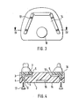
- FIGS. 3 and 4 has the base plate on the underside 14 with slots 11 with a conical cross section, through which the toothed ring carrier can be screwed from below with screws 17.
- This enables a rigid and non-detachable connection between the base plate 2 and the ring gear carrier 1, so that milling work on individual parts can be carried out directly on the device according to the invention without it being necessary to remove the individual tooth segments and to clamp them separately.
- a magnet 18 is embedded in a central area, with the aid of which the device according to the invention can be attached to an articulator.
- 25 g of fine iron powder ( ⁇ 100 ⁇ m, average particle size about 15 pm) are mixed with 10 g of 2,2-bis- [p- (ß-hydroxyethoxy) phenyl] propane-bis-ß-ethylene iminobutyrate (polymerizable / prepolymer) and 300 mg of 2-ethylhexyl ethyl sulfonium isobutyronitrile fluoroborate (polymerization initiator) processed into a homogeneous mixture.
- This readily flowable mixture is poured into the recess 6 of a base plate 2 made of polypropylene immediately after mixing and allowed to harden there. The mass, which remains flowable at room temperature for about 5 minutes, is cured after about 15 minutes.
- the finished Gear ring carrier 1 removed from the base plate 2.
- the top 13 of the sprocket carrier is glued flat with a sprocket model 15 made of plaster with cyanoacrylate adhesive.
- the finished arrangement of the ring gear and the ring gear carrier is separated by vertical cuts into individual tooth segments 19, which can easily be put together again with the aid of the base plate 2 to form the complete ring gear model.
Abstract
Description
- Die Erfindung betrifft eine Vorrichtung zur Fertigung von Zahnkranzmodellen, insbesondere von sog. Sägemodellen, bei denen die Zähne einzeln oder in Gruppen lösbar mit einer Sockelplatte verbunden sind.
- Für verschiedene zahntechnische Arbeiten ist es erforderlich, über ein massgetreues Zahn- und Kiefermodell, ein sog. Meistermodell, zu verfügen. Zur Herstellung eines derartigen Modells wird ein dem Kiefer des Patienten entnommener Abdruck mit Gips ausgegossen. Das erhaltene Zahnkranzmodell wird in der Regel auf einer Sockelplatte, die meistens ebenfalls aus Gips besteht, befestigt. Für bestimmte zahntechnische Arbeiten, z.B. beim Anpassen von Kronen oder Brücken, ist es erwünscht, dass einzelne Zähne oder Zahngruppen in Form von Segmenten von der Sockelplatte entfernt und nach der Bearbeitung wieder passgenau eingesetzt werden können. Hierzu sind bei herkömmlichen Modellen Stifte, sog. Dowel-pins, vorgesehen, die an einem Ende fest mit den Zahnkranzsegmenten verbunden sind und deren freie Enden in entsprechende Löcher, die in der Sockelplatte vorgesehen sind, passen. Beim Herausziehen der Dowel-pins aus den Löchern entstehen relativ hohe Friktionskräfte, die es verhindern, dass sich die Segmente ungewollt von der Sockelplatte lösen.
- Diese Dowel-pin-Technik ist jedoch u.a. mit folgenden Nachteilen behaftet:
- 1. Die Stifte müssen genau parallel zueinander angeordnet sein, da ansonsten ein problemfreies Entnehmen und Wiedereinsetzen von Zahnkranzsegmenten nicht möglich ist. Zum Setzen der Stifte werden relativ aufwendige Pin-Setzgeräte verwendet.
- 2. Ein präziser Sitz der einzelnen Zahnkranzsegmente ist nur schwer zu erreichen, insbesondere wenn sich an Stiften und Löchern durch häufiges Herausnehmen Abnützungserscheinungen einstellen.
- 3. Die Sockelplatte kann in der Regel nur einmal verwendet werden, da Stifte und Löcher einander genau zugeordnet sind und es in der Praxis nicht möglich ist, an einem Zahnkranz die Pins genau passend zu einer vorhandenen, bereits mit Bohrlöchern versehenen Sockelplatte einzusetzen.
- 4. Modelle für Kronen und Brücken werden in der Regel aus Wachs hergestellt. Bei sämtlichen Modellen, bei denen die Zahnkranzmodelle durch Friktionskräfte an der Sockelplatte halten, besteht der schwerwiegende Nachteil, dass zum Entnehmen der Segemte relativ hohe Friktionskräfte zu überwinden sind. Unvermeidlich kommt es dabei zu Verkantungen, so dass leicht Beschädigungen der in Wachs modellierten Teile eintreten.
- Man hat bereits versucht, bei derartigen Zahnmodellen auf die Verwendung von Dowel-pins zu verzichten. Durchwegs wurden dabei Lösungsmöglichkeiten vorgeschlagen, bei denen der Zusammenhalt zwischen Zahnkranz und Sockelplatte ebenfalls durch Friktionskräfte gewährleistet wird. So ist in der europäischen Patentanmeldung 44 223 ein derartiges Modell beschrieben, dessen Zahnkranz an der Unterseite ein Muster aus parallelen Zickzack-Rippen und -Rillen aufweist. Auf der Oberseite der Sockelplatte ist ein hierzu komplementäres Muster-vorgesehen. Werden Zahnkranz und Sockelplatte aufeinandergesetzt, so greifen Rippen und Rillen ineinander und sorgen durch Friktionskräfte für einen Zusammenhalt der beiden Teile. Auch hier kommt es zu den vorstehend erläuterten Schwierigkeiten, insbesondere besteht die Gefahr der unter 4. beschriebenen Beschädigung von aus Wachs gefertigten Modellteilen, wenn die einzelnen Zahnsegmente von der Sockelplatte gelöst werden.
- Aufgabe der Erfindung ist es, eine Vorrichtung zur Fertigung von Zahnkranzmodellen mit abnehmbaren Zahnkranzsegmenten bereitzustellen, bei der die Zahnkranzsegmente einfach und passgenau an der Sockelplatte befestig werden können, ohne dass sich der Sitz der Segmente nach wiederholtem Abnehmen lockert und ohne dass die Gefahr einer Beschädigung von aus Wachs gefertigten Modellen besteht.
- Diese Aufgabe wird erfindungsgemäss dadurch gelöst, dass bei einer Vorrichtung zur Fertigung von Zahnkranzmodellen, die aus einem insbesondere etwa U-förmigen Zahnkranzträger und einer lösbar damit verbundenen Sockelplatte besteht, der Zusammenhalt zwischen dem Zahnkranzträger und der Sockelplatte durch magnetische Kräfte erfolgt.
- Hierzu ist sowohl im Zahnkranzträger als auch in der Sockelplatte jeweils ein magnetisches Material enthalten. Unter dem Ausdruck "magnetisches Material" ist zu verstehen, dass zumindest in einem der beiden Teile ein permanent magnetisches und im jeweils anderen Teil ein magnetisierbares oder ebenfalls permanent magnetisches Material enthalten sind.
- Vorzugsweise werden als magnetische Materialien gefüllte Kunststoffe verwendet, die den Vorteil bieten, dass sie leicht verformbar und bearbeitbar sind. Als Füllstoffe kommen übliche magnetische Werkstoffe in Pulverform in Frage, z.B. Eisen, Kobalt, Nickel, deren Legierungen, Ferrate und dergl.
- Die Anwendung magnetischer Kräfte zur Gewährleistung des Zusammenhalts zwischen Zahnkranzträger und Sockelplatte bietet den Vorteil, dass die den Zusammenhalt bewirkende Kraft immer konstant bleibt und keiner Beeinträchtigung durch Materialabnutzung unterliegt. Da Friktionskräfte weitgehend ausgeschaltet sind, ist es auch nicht erforderlich, zu deren überwindung ruckartige Bewegungen auszuführen, bei denen es leicht zu Verkantungen und somit zu einer Beschädigung von Wachsteilen kommt. Ferner ist eine Mehrfachverwendung der Sockelplatte ohne Schwierigkeiten möglich. Schliesslich bietet sich der Vorteil, dass sich die Vorrichtung zeitsparend herstellen lässt.
- Gemäss einer bevorzugten Ausführungsform der erfindungsgemässen Vorrichtung besteht der Zahnkranzträger im wesentlichen aus einem U-förmigen, ein magnetisches Material enthaltenden Steg mit nach unten konisch zulaufenden Seitenwänden. Die Sockelplatte weist hierbei eine zum Steg komplementäre Ausnehmung auf, in dessen Oberflächenbereich sich ebenfalls magnetisches Material befindet. Dieser konische Steg erleichtert die exakte Zuordnung der Zahnsegmente zur Sockelplatte. Aufgrund des konischen Querschnitts wird gewährleistet, dass beim Herausnehmen der Segmente nur vernachlässigbar geringe Friktionskräfte auftreten, was die vorstehend geschilderten Vorteile mit sich bringt.
- Zweckmässigerweise weist der Steg einen parallel oder in spitzem Winkel zur Ebene der Sockelplatte verlaufenden Absatz auf, der einem weiteren Absatz in der Sockelplatte entspricht. Vorzugsweise verläuft der Absatz an der Innenwand der Sockelplatte nicht parallel zur Ebene der Sockelplatte, sondern ist um einen geringen Winkel, z.B. 5 bis 10°, zum Zentrum der Sockelplatte hin geneigt, damit gewisse Toleranzen'bei der Passung zwischen Zahnkranzträger und Sockelplatte leichter ausgeglichen werden können. Entsprechend muss dann der Absatz im Steg des Zahnkranzträgers geneigt sein. Im Bereich des Absatzes in der Sockelplatte sind vorzugsweise Permanentmagneten eingelassen, die den Zusammenhalt mit dem vorzugsweise aus einem mit magnetischem Material gefüllten Kunststoff bestehenden Steg gewährleisten.
- Um die Zuordnung der Segmente der Sockelplatte zu erleichtern und um die Passgenauigkeit zu erhöhen, sind an den konischen Seitenwänden des Stegs vorzugsweise Rippen angeordnet, die im rechten Winkel zu dessen Oberseite und parallel zueinander laufen. An der Ausnehmung in der Sockelplatte sind dann in entsprechender Weise hierzu komplementäre Rillen vorgesehen.
- Gemäss einer weiteren bevorzugten Ausführungsform sind an der Unterseite der Sockelplatte Schlitze oder Bohrungen vorgesehen, durch die der Zahnkranzträger von unten mit der Sockelplatte verschraubt werden kann. Dies bietet den Vorteil, dass verschiedene Arbeiten, insbesondere Fräsarbeiten, direkt am Zahnkranzmodell möglich sind.
- Besonders vorteilhaft ist es, den in die Sockelplatte eingelassenen-Magneten so auszubilden, dass er nach unten entfernbar ist. Der Magnet kann dann beispielsweise durch Schrauben, einen druckknopfartigen Verschluss oder eine Art Bajonettverschluss festgehalten werden. Dadurch wird nach Entfernung des Magneten die Entnahme der Zahnkranzsegmente besonders einfach möglich. Ausserdem kann, falls die Sockelplatte beschädigt ist, der relativ teure Magnet in eine andere Sockelplatte umgesetzt werden.
- Weiterhin hat es sich als vorteilhaft herausgestellt, wenn beim Giessen des Wurzelkranzes die Schlitze oder Bohrungen an der Unterseite der Sockelplatte durch einen Platzhalter, z.B. aus Silicongummi, verschlossen werden, damit ein Auslaufen der fliessfähigen Masse nicht möglich ist.
- Schliesslich kann an der Unterseite der Sockelplatte im zentralen Bereich ein Magnet eingelassen sein, mit dem die Vorrichtung an einem Artikulator befestigt werden kann.
- Zweckmässigerweise wird die erfindungsgemässe Vorrichtung in verschiedenen Grössen zur Anpassung an die Grössenverhältnisse im Ober- und Unterkiefer bereitgestellt.
- Nachstehend wird eine bevorzugte Ausführungsform der Erfindung anhand der Zeichnung näher erläutert. Es zeigen:
- Fig. 1 eine in Einzelteile aufgelöste, perspektivische Ansicht einer erfindungsgemässen Vorrichtung zusammen mit einem Zahnkranz;
- Fig. 2 einen Querschnitt entlang II-II des Zahnkranzträgers von Fig. 1;
- Fig. 3 eine Unteransicht einer Sockelplatte mit Verschraubung des Zahnkranzträgers und
- Fig. 4 einen Querschnitt entlang IV-IV von Fig. 3.
- In Fig. 1 ist ein Zahnkranzträger 1 gezeigt, der im wesentlichen aus einem in etwa U-förmigen Steg besteht, dessen Seitenwände 4, 5 nach unten konisch aufeinander zulaufen. Die Seitenwände 4, 5 sind mit parallel verlaufenden, im rechten Winkel zur Oberseite 13 des Zahnkranzträgers angeordnete Rippen 9 versehen.
- Aus dem in Fig. 2 dargestellten Querschnitt des Zahnkranzträgers 1 ist ersichtlich, dass sich in der inneren Seitenwand 5 ein Absatz 7 befindet.
- Beim Einsatz der erfindungsgemässen Vorrichtung in der Praxis wird auf den Zahnkranzträger 1 der durch Ausgiessen des Kieferabgusses erhaltene eigentliche Zahnkranz 15 befestigt: Zweckmässigerweise geschieht dies durch flächige Verklebung mittels eines rasch abbindenden Klebers. Die erhaltene Anordnung aus Zahnkranz und Zahnkranzträger kann dann je nach Bedarf durch senkrechte Sägeschnitte zu Segmenten 19 von einzelnen Zähnen oder Zahngruppen aufgeteilt werden.
- Zur Herstellung des Zahnkranzträgers kann generell ein fliessfähiges, erhärtendes Monomeres und/oder Präpolymeres eingesetzt werden, das eine geringe Schrumpfung aufweist und mit einem magnetischen oder magnetisierbaren Metallpulver gefüllt ist.
- In der Sockelplatte 2 von Fig..1 ist eine U-förmige Ausnehmung 6 vorgesehen, die komplementär zur Form des Stegs 3 ist, d.h. die Seitenwände der Ausnehmung 6 verlaufen nach unten konisch aufeinander zu und ein Absatz 8 an der Innenwand entspricht dem Absatz 7 des Stegs 3. Ferner sind an den Aussenwänden der Ausnehmung 6 parallel zueinander verlaufende, im rechten Winkel zur Oberseite 16 der Sockelplatte 2 angeordnete Rillen 10 vorgesehen, die zur Aufnahme der Rippen 9 dienen. Somit ergibt sich an den Seitenwänden des Stegs und der Ausnehmung jeweils ein zickzack-förmiges Muster. Diese zueinander komplementären Muster erleichtern ein passgenaues Einsetzen des Zahnkranzträgers 1 in die Ausnehmung 6. Aufgrund des konisch verlaufenden Querschnitts des Stegs 3 und der Ausnehmung 6 ergeben sich beim Herausnehmen des Zahnkranzträgers 1 nur sehr geringe Friktionskräfte. Vielmehr wird der Zusammenhalt mit dem aus magnetischem Material bestehenden Steg 3 durch flächige Magneten 12 gewährleistet, die im Bereich des Absatzes 8 angeordnet sind.
- Zur Herstellung der erfindungsgemässen Vorrichtung geht man von einem Rohling für die Sockelplatte aus und stellt durch spanabhebende Bearbeitung die Ausnehmung 6 her. Eine andere Möglichkeit besteht darin, dass die Sockelplatte unter Verwendung entsprechender Formen durch Spritzgiessen oder ähnliche Verformungstechniken auf einmal hergestellt wird.
- In die Ausnehmung 6 wird dann das vorerwähnte fliessfähige Material zur Herstellung des Zahnkranzträgers gegossen und aushärten gelassen. Da sich der Giessvorgang beliebig oft wiederholen lässt, ist eine Mehrfachverwendung der Sockelplatte gewährleistet. Eine andere Möglichkeit ist die separate Herstellung des Zahnkranzträgers durch Spritzgiessen oder eine andere präzise For.mgebungstechnik. Damit sich der polymerisierte Zahnkranzträger gut von der Sockelplatte lösen lässt, soll letztere eine möglichst glatte Oberfläche aufweisen. Als Materialien für die Sockelplatte kommen Kunststoffe und Metalle in Frage. Beispiele hierfür sind Polyoxymethylen (Delrin), Polyäthylen, Polypropylen, Polyamid, Polymethacrylat (Plexiglas), Polyvinylchlorid, Messing und Aluminium.
- Ein Beispiel für einen zum Aufkleben des Zahnkranzes auf dem Zahnkranzträger geeigneten Klebstoff ist Cyanacrylatkleber.
- Gemäss der in den Figg. 3 und 4 gezeigten Ausführungsform weist die Sockelplatte auf der Unterseite 14 Schlitze 11 mit konischem Querschnitt auf, durch die der Zahnkranzträger von unten her mit Schrauben 17 angeschraubt werden kann. Dies ermöglicht eine starre und unlösbare Verbindung zwischen Sockelplatte 2 und Zahnkranzträger 1, so dass Fräsarbeiten an einzelnen Teilen direkt an der erfindungsgemässen Vorrichtung durchgeführt werden können, ohne dass es erforderlich ist, die einzelnen Zahnsegmente herauszunehmen und getrennt einzuspannen.
- Auf der Unterseite der Sockelplatte 2 ist in einem zentralen Bereich ein Magnet 18 eingelassen, mit dessen Hilfe die erfindungsgemässe Vorrichtung an einem Artikulator angebracht werden kann.
- Das nachstehende Beispiel erläutert die Erfindung.
- 25 g feines Eisenpulver ( < 100 µm, mittlere Teilchengrösse etwa 15 pm) werden mit 10 g 2,2-Bis-[p-(ß-hydroxyäthoxy)-phenyl]-propan-bis-ß-äthyleniminobutyrat (polymerisierbares/Präpolymeres) und 300 mg 2-Äthylhexyl-äthyl-sulfoniumisobutyronitril-fluoroborat (Polymerisationsinitiator) zu einer homogenen Mischung verarbeitet. Diese gut fliessfähige Mischung wird direkt nach dem Anmischen in die Ausnehmung 6 einer Sockelplatte 2 aus Polypropylen gegossen und dort aushärten gelassen. Die Masse, die bei Raumtemperatur etwa 5 Minuten fliessfähig bleibt, ist nach etwa 15 Minuten ausgehärtet. Nach der Aushärtung wird der fertige Zahnkranzträger 1 aus der Sockelplatte 2 entnommen. Die Oberseite 13 des Zahnkranzträgers wird flächig mit einem aus Gips hergestellten Zahnkranzmodell 15 mit Cyanacrylatkleber verklebt. Die fertige Anordnung aus Zahnkranz und Zahnkranzträger wird durch senkrechte Schnitte in einzelne Zahnsegmente 19 aufgetrennt, die sich unter Zuhilfenahme der Sockelplatte 2 leicht wieder zum vollständigen Zahnkranzmodell zusammensetzen lassen.
Claims (10)
Priority Applications (1)
| Application Number | Priority Date | Filing Date | Title |
|---|---|---|---|
| AT86105852T ATE45872T1 (de) | 1985-04-30 | 1986-04-28 | Vorrichtung zur fertigung von zahnkranzmodellen. |
Applications Claiming Priority (2)
| Application Number | Priority Date | Filing Date | Title |
|---|---|---|---|
| DE3515510 | 1985-04-30 | ||
| DE19853515510 DE3515510A1 (de) | 1985-04-30 | 1985-04-30 | Vorrichtung zur fertigung von zahnkranzmodellen |
Publications (2)
| Publication Number | Publication Date |
|---|---|
| EP0200193A1 true EP0200193A1 (de) | 1986-11-05 |
| EP0200193B1 EP0200193B1 (de) | 1989-08-30 |
Family
ID=6269452
Family Applications (1)
| Application Number | Title | Priority Date | Filing Date |
|---|---|---|---|
| EP86105852A Expired EP0200193B1 (de) | 1985-04-30 | 1986-04-28 | Vorrichtung zur Fertigung von Zahnkranzmodellen |
Country Status (5)
| Country | Link |
|---|---|
| US (1) | US4767330A (de) |
| EP (1) | EP0200193B1 (de) |
| JP (1) | JPS61253053A (de) |
| AT (1) | ATE45872T1 (de) |
| DE (2) | DE3515510A1 (de) |
Cited By (3)
| Publication number | Priority date | Publication date | Assignee | Title |
|---|---|---|---|---|
| GB2230958A (en) * | 1989-04-13 | 1990-11-07 | Bishop Bailey Colin | Dental model holder |
| FR2757372A1 (fr) * | 1996-12-24 | 1998-06-26 | Giordano Bruno | Support de moulage pour prothese dentaire, procede pour realiser un moulage avec un tel support, et moulage pour ce support |
| WO2013092980A1 (de) * | 2011-12-23 | 2013-06-27 | Degudent Gmbh | Verfahren zum herstellen und tragplatte zur aufnahme eines zahntechnischen modells |
Families Citing this family (78)
| Publication number | Priority date | Publication date | Assignee | Title |
|---|---|---|---|---|
| DE3716143A1 (de) * | 1987-05-14 | 1988-12-08 | Baumann Karsten | Sockel zur halterung des gipsmodelles eines zahnkranzes |
| JPH0364620U (de) * | 1989-10-31 | 1991-06-24 | ||
| US5129822A (en) * | 1990-03-19 | 1992-07-14 | Dobbs T Charles | Dental casting apparatus and method |
| US5207574A (en) * | 1990-12-03 | 1993-05-04 | Garland James K | Dental model and process of making same |
| JPH0622988A (ja) * | 1992-04-21 | 1994-02-01 | Shiken:Kk | 歯科技工用可撤式模型およびその製造法 |
| USRE35263E (en) * | 1992-06-19 | 1996-06-04 | The Silva Group, Inc. | Method and apparatus for fabricating dental models |
| US5425636A (en) * | 1992-11-23 | 1995-06-20 | Ghim; Duke K. | Articulator for dental mold |
| US5573397A (en) * | 1993-07-06 | 1996-11-12 | S-Tec, Inc. | Method for creating a universal mount for dental articulators |
| US5393227A (en) * | 1994-02-25 | 1995-02-28 | Keypro Innovations, Inc. | Dental impression handling tool and method |
| US5996963A (en) * | 1997-02-14 | 1999-12-07 | Ceramco Inc. | Dental casting mold device |
| WO2000004843A1 (en) * | 1998-07-23 | 2000-02-03 | Walter Jose E | Disposable articulator having tray support with opening which accepts a projection from a tray |
| US6106284A (en) * | 1999-01-15 | 2000-08-22 | Cronin; Richard J. | Dental cast tray assembly |
| US6511318B2 (en) | 1999-04-07 | 2003-01-28 | Nu-Tek Dental, Llc | Dental articulator |
| US6318999B1 (en) | 1999-04-07 | 2001-11-20 | Nu-Tek Dental, Llc | Dental articulator |
| USD433136S (en) * | 1999-07-06 | 2000-10-31 | Huffman Ronald E | Dental model base |
| USD429815S (en) * | 1999-07-06 | 2000-08-22 | Huffman Ronald E | Dental model base |
| USD433754S (en) * | 1999-07-06 | 2000-11-14 | Huffman Ronald E | Dental model base |
| USD430672S (en) * | 1999-07-06 | 2000-09-05 | Huffman Ronald E | Dental model base |
| US7210931B1 (en) | 1999-07-07 | 2007-05-01 | Ronald E. Huffman | Dental model base assembly |
| DE19934268C2 (de) * | 1999-07-21 | 2002-02-14 | Michael Azzaretto | Tragplatte für ein Gebißmodell |
| US6497574B1 (en) * | 2000-09-08 | 2002-12-24 | Align Technology, Inc. | Modified tooth positioning appliances and methods and systems for their manufacture |
| ATE555743T1 (de) * | 2000-11-08 | 2012-05-15 | Straumann Inst Ag | (dentale) oberflächenerfassung und erzeugung |
| US6425759B1 (en) | 2000-11-15 | 2002-07-30 | Richard J. Cronin | Dental cast tray assembly |
| US6439884B1 (en) | 2000-11-15 | 2002-08-27 | Richard J. Cronin | Dental cast tray assembly |
| JP4667597B2 (ja) * | 2000-11-22 | 2011-04-13 | 豊之 倉井 | 歯科技工におけるクラウン製作法 |
| USD452567S1 (en) | 2001-01-26 | 2001-12-25 | Ronald E. Huffman | Full arch dental model base having a single row of apertures |
| USD452319S1 (en) | 2001-01-26 | 2001-12-18 | Ronald E. Huffman | Quadrant attachment plate |
| US7044734B2 (en) * | 2001-01-26 | 2006-05-16 | Huffman Ronald E | Encased stone dental model base body and method |
| USD452566S1 (en) | 2001-01-26 | 2001-12-25 | Ronald E. Huffman | Full arch dental model base having a double row of apertures |
| USD452009S1 (en) | 2001-01-26 | 2001-12-11 | Ronald E. Huffman | Quadrant dental model base having a single row of apertures |
| USD452321S1 (en) | 2001-01-26 | 2001-12-18 | Ronald E. Huffman | Quadrant dental model base having a double row of apertures |
| USD452010S1 (en) | 2001-01-26 | 2001-12-11 | Ronald E. Huffman | Full arch attachment plate |
| USD452320S1 (en) | 2001-01-26 | 2001-12-18 | Ronald E. Huffman | Encased stone dental model base |
| US6471513B1 (en) | 2001-01-29 | 2002-10-29 | Ronald E. Huffman | Dental model base assembly |
| USD452322S1 (en) | 2001-02-27 | 2001-12-18 | Ronald E. Huffman | Projecting pin dental model base with detachable articulator attachment bar |
| USD452568S1 (en) | 2001-02-27 | 2001-12-25 | Ronald E. Huffman | Projecting pin dental model base |
| US7713063B2 (en) * | 2001-05-03 | 2010-05-11 | Lee Charles Q | Dental training device |
| USD456903S1 (en) | 2001-05-09 | 2002-05-07 | Ronald E. Huffman | Quadrant dental model base with projecting variable height pins |
| USD457637S1 (en) | 2001-05-09 | 2002-05-21 | Ronald E. Huffman | Encased stone quadrant, winged dental model base |
| USD456904S1 (en) | 2001-05-09 | 2002-05-07 | Ronald E. Huffman | Projecting pin quadrant dental model base |
| USD456902S1 (en) | 2001-05-09 | 2002-05-07 | Ronald E. Huffman | Hollow body full arch dental model base |
| USD457964S1 (en) | 2001-05-09 | 2002-05-28 | Ronald E. Huffman | Full arch dental model base with projecting variable height pins |
| USD457243S1 (en) | 2001-05-09 | 2002-05-14 | Ronald E. Huffman | Solid quadrant winged dental model base |
| USD457963S1 (en) | 2001-05-09 | 2002-05-28 | Ronald E. Huffman | Full arch dental model base with projecting variable height pins and removeable attachment bar |
| USD457636S1 (en) | 2001-05-09 | 2002-05-21 | Ronald E. Huffman | Solid full arch dental model base |
| USD464733S1 (en) | 2001-09-19 | 2002-10-22 | Ronald E. Huffman | Dental model base having two rows of pins |
| USD464732S1 (en) | 2001-09-19 | 2002-10-22 | Ronald E. Huffman | Dental model base having two rows of stationary pins for random location of teeth |
| USD464432S1 (en) | 2001-09-28 | 2002-10-15 | Ronald E. Huffman | Encased stone dental model base |
| USD465027S1 (en) | 2001-09-28 | 2002-10-29 | Ronald Huffman | Dental model base having a single row of apertures |
| USD464431S1 (en) | 2001-09-28 | 2002-10-15 | Ronald E. Huffman | Dental model base having a double row of apertures |
| US7108507B2 (en) | 2002-08-07 | 2006-09-19 | Huffman Ronald E | Dental model pouring jig |
| DE10357699A1 (de) * | 2003-12-09 | 2005-07-28 | Degudent Gmbh | Verfahren zur Ermittlung der Form eines Restzahnbereichs |
| US7922490B2 (en) * | 2004-12-14 | 2011-04-12 | Align Technology, Inc. | Base for physical dental arch model |
| US8636513B2 (en) * | 2004-12-14 | 2014-01-28 | Align Technology, Inc. | Fabricating a base compatible with physical tooth models |
| US20060127858A1 (en) * | 2004-12-14 | 2006-06-15 | Huafeng Wen | Producing accurate base for a dental arch model |
| US20070092853A1 (en) * | 2005-10-24 | 2007-04-26 | Liu Frank Z | Multi-layer casting methods and devices |
| USD530014S1 (en) | 2004-11-05 | 2006-10-10 | Ronald E. Huffman | Dental model base quadrant with a plurality of indexing pins |
| USD529177S1 (en) | 2004-11-05 | 2006-09-26 | Ronald E. Huffman | Dental model base with a plurality of indexing pins |
| US20060172250A1 (en) * | 2005-02-03 | 2006-08-03 | Huafeng Wen | Inelligent tracking of dental devices |
| US7819659B2 (en) * | 2005-04-25 | 2010-10-26 | Align Technology, Inc. | System for organizing dental aligners |
| US8337199B2 (en) * | 2005-03-07 | 2012-12-25 | Align Technology, Inc. | Fluid permeable dental aligner |
| US20060275731A1 (en) * | 2005-04-29 | 2006-12-07 | Orthoclear Holdings, Inc. | Treatment of teeth by aligners |
| USD529614S1 (en) | 2005-06-10 | 2006-10-03 | Ronald E. Huffman | Opposing dental model base quadrant |
| USD529178S1 (en) | 2005-06-10 | 2006-09-26 | Ronald E. Huffman | Opposing dental model base |
| ITTO20050437A1 (it) * | 2005-06-22 | 2006-12-23 | Buccia Alberto Bianchetto | Procedimento per la realizzazione di modelli dentali di precisione nel campo odontotecnico e modelli relativi |
| US20070111155A1 (en) * | 2005-11-14 | 2007-05-17 | Kamil Karroum | Dental articulator systems and methods |
| JP4822818B2 (ja) * | 2005-11-28 | 2011-11-24 | 純男 関 | 歯科補綴物用可撤模型の基台成形トレー |
| JP2007151767A (ja) * | 2005-12-02 | 2007-06-21 | Dentasu:Kk | 間接法作業模型 |
| US7690919B2 (en) | 2006-03-28 | 2010-04-06 | Huffman Ronald E | Dental articulator |
| US20070292818A1 (en) * | 2006-06-20 | 2007-12-20 | Michael Sullivan | Dental casting tray assemblies |
| WO2008004758A1 (en) * | 2006-07-06 | 2008-01-10 | Gee Su Kim | Modeling structure for preparing dental prosthesis |
| DE102007063233B3 (de) * | 2007-12-31 | 2009-06-25 | Michael Vanek | Verfahren zum Unterfüttern einer Zahnprothese |
| US20090208895A1 (en) * | 2008-02-17 | 2009-08-20 | Chao-Hung Lin | Plaster dental cast gum plate molding mold |
| DE102011119511A1 (de) * | 2011-03-18 | 2012-09-20 | Dreve Prodimed Gmbh | Dentalmodell |
| US9375298B2 (en) * | 2012-02-21 | 2016-06-28 | Align Technology, Inc. | Dental models and related methods |
| US11612463B2 (en) | 2013-11-21 | 2023-03-28 | William C. Vuillemot | Apparatus for in situ restoration of unconstrained dental structure |
| US9717573B2 (en) * | 2013-11-21 | 2017-08-01 | William C. Vuillemot | In-situ dental restoration process and apparatus |
| CN109674549B (zh) * | 2019-01-17 | 2022-03-18 | 杭州佳杰齿科有限公司 | 一种义齿模型底座 |
Citations (6)
| Publication number | Priority date | Publication date | Assignee | Title |
|---|---|---|---|---|
| US3702027A (en) * | 1971-03-08 | 1972-11-07 | So Mar Dental Studios Inc | Die holder for dental laboratory |
| WO1979000076A1 (en) * | 1977-08-01 | 1979-02-22 | Jet Ceramic Dental Gmbh | Device for producing a working model for making dental prostheses |
| DE2835094B2 (de) * | 1978-08-10 | 1980-10-02 | Dietmar 8000 Muenchen Tretschoks | Vorrichtung zum Anfertigen von Kronen, Brücken, Zahnprothesen o.dgl |
| EP0044223A1 (de) * | 1980-07-11 | 1982-01-20 | John Thomas Felstead | Vorrichtung und Verfahren zum Herstellen eines Zahnabdrucks |
| GB2092058A (en) * | 1981-02-02 | 1982-08-11 | Kv 33 Corp | Mould for dental models |
| EP0116163A1 (de) * | 1983-01-19 | 1984-08-22 | Manfred P.Dr. Zeiser | Gebissmodell und Sockelplatte für ein Gebissmodell |
Family Cites Families (11)
| Publication number | Priority date | Publication date | Assignee | Title |
|---|---|---|---|---|
| US2985961A (en) * | 1956-11-19 | 1961-05-30 | Jacob D Schwartz | Trial denture base plates |
| US2959832A (en) * | 1957-10-31 | 1960-11-15 | Baermann Max | Flexible or resilient permanent magnets |
| US2947646A (en) * | 1958-01-07 | 1960-08-02 | Eastman Kodak Co | Colloidal dispersion of metals in plastics |
| US3650032A (en) * | 1970-02-11 | 1972-03-21 | Glynn E Perkins | Magnetic tool-positioning apparatus |
| US4017972A (en) * | 1975-07-07 | 1977-04-19 | Glenn Edward C | Dowel pin positioner |
| FR2326908A1 (fr) * | 1975-10-06 | 1977-05-06 | Segura Claude | Dispositif permettant l'elaboration precise d'une prothese dentaire conjointe |
| US4174570A (en) * | 1977-07-14 | 1979-11-20 | Schwartz Donald E | Magnetic pin setter useful in dentistry |
| US4494934A (en) * | 1981-02-02 | 1985-01-22 | Kv33 Corporation | Dental model base |
| DE3214856A1 (de) * | 1982-04-21 | 1983-10-27 | Heinz 7075 Mutlangen Hampel | Halterung fuer zahntechnische modelle |
| DE3315870C2 (de) * | 1983-04-30 | 1986-10-02 | Scheu-Dental Inhaber Rudolf Scheu, Herstellung und Vertrieb von Dentalbedarf, 5860 Iserlohn | Zahn- und Kiefermodell |
| US4508506A (en) * | 1983-10-31 | 1985-04-02 | Jackson Robert M | Process and apparatus for the preparation of dental models |
-
1985
- 1985-04-30 DE DE19853515510 patent/DE3515510A1/de not_active Withdrawn
-
1986
- 1986-04-28 DE DE8686105852T patent/DE3665256D1/de not_active Expired
- 1986-04-28 JP JP61097020A patent/JPS61253053A/ja active Pending
- 1986-04-28 AT AT86105852T patent/ATE45872T1/de not_active IP Right Cessation
- 1986-04-28 EP EP86105852A patent/EP0200193B1/de not_active Expired
- 1986-04-30 US US06/857,930 patent/US4767330A/en not_active Expired - Fee Related
Patent Citations (6)
| Publication number | Priority date | Publication date | Assignee | Title |
|---|---|---|---|---|
| US3702027A (en) * | 1971-03-08 | 1972-11-07 | So Mar Dental Studios Inc | Die holder for dental laboratory |
| WO1979000076A1 (en) * | 1977-08-01 | 1979-02-22 | Jet Ceramic Dental Gmbh | Device for producing a working model for making dental prostheses |
| DE2835094B2 (de) * | 1978-08-10 | 1980-10-02 | Dietmar 8000 Muenchen Tretschoks | Vorrichtung zum Anfertigen von Kronen, Brücken, Zahnprothesen o.dgl |
| EP0044223A1 (de) * | 1980-07-11 | 1982-01-20 | John Thomas Felstead | Vorrichtung und Verfahren zum Herstellen eines Zahnabdrucks |
| GB2092058A (en) * | 1981-02-02 | 1982-08-11 | Kv 33 Corp | Mould for dental models |
| EP0116163A1 (de) * | 1983-01-19 | 1984-08-22 | Manfred P.Dr. Zeiser | Gebissmodell und Sockelplatte für ein Gebissmodell |
Cited By (4)
| Publication number | Priority date | Publication date | Assignee | Title |
|---|---|---|---|---|
| GB2230958A (en) * | 1989-04-13 | 1990-11-07 | Bishop Bailey Colin | Dental model holder |
| FR2757372A1 (fr) * | 1996-12-24 | 1998-06-26 | Giordano Bruno | Support de moulage pour prothese dentaire, procede pour realiser un moulage avec un tel support, et moulage pour ce support |
| WO2013092980A1 (de) * | 2011-12-23 | 2013-06-27 | Degudent Gmbh | Verfahren zum herstellen und tragplatte zur aufnahme eines zahntechnischen modells |
| US10105200B2 (en) | 2011-12-23 | 2018-10-23 | Degudent Gmbh | Method for producing a dental model and carrying plate for receiving same |
Also Published As
| Publication number | Publication date |
|---|---|
| DE3665256D1 (en) | 1989-10-05 |
| ATE45872T1 (de) | 1989-09-15 |
| EP0200193B1 (de) | 1989-08-30 |
| JPS61253053A (ja) | 1986-11-10 |
| DE3515510A1 (de) | 1986-11-06 |
| US4767330A (en) | 1988-08-30 |
Similar Documents
| Publication | Publication Date | Title |
|---|---|---|
| EP0200193B1 (de) | Vorrichtung zur Fertigung von Zahnkranzmodellen | |
| DE3825014C2 (de) | ||
| EP0291821B1 (de) | Sockel zur Halterung des Gipsmodelles eines Zahnkranzes | |
| DE3203259A1 (de) | Form fuer dentalmodelle | |
| DE2917167A1 (de) | Gebissartikulator | |
| EP3200720B1 (de) | Form zur herstellung eines vorgeformten prothesenbasisrohlings | |
| DE102010016847A1 (de) | Dentalmodellrohling | |
| DE102006021476B3 (de) | Magnetisches Abdrucksystem | |
| DE2835094C3 (de) | Vorrichtung zum Anfertigen von Kronen, Brücken, Zahnprothesen o.dgl. | |
| DE3237229A1 (de) | Modellsockel zur herstellung von zahnersatz | |
| DE10241857B4 (de) | Verfahren und Vorrichtung zur Anfertigung einer Form, insbesondere einer Muffel, für die Herstellung von Zahnersatz-Objekten | |
| DE3117506A1 (de) | "magnetsockelform zur herstellung von durch magnetkraft zusammengehaltenen trennsockeln an kiefermodellen" | |
| EP3930625A1 (de) | Verfahren zum herstellen eines formkörpers und formkörper | |
| DE102004016199B3 (de) | Zahnersatzmodellplatte | |
| DE3719039A1 (de) | Verfahren und vorrichtung zur herstellung eines saegemodells | |
| DE102006042919B3 (de) | Kiefer-Implantat-System, und Verfahren zum Herstellen eines Zahnersatzes | |
| DE19954732C2 (de) | Halter für ein Modell | |
| DE4013076A1 (de) | Kuevette und verfahren zum herstellen von modellduplikaten | |
| DE19547137C2 (de) | Vorrichtung zur Halterung von Zahn- und/oder Kiefermodellteilen | |
| EP3064169B1 (de) | Verfahren zur herstellung einer dentalkeramik sowie dentalkeramik-erzeugungsvorrichtung | |
| DE10061088A1 (de) | Reprolöffel | |
| WO2022049078A1 (de) | Verfahren zur herstellung eines zur montage in einen artikulator bestimmten kiefermodells | |
| EP0710467A2 (de) | Anordnung zum Halten eines zahnmedizinisches Modells in einem Modellbehalter | |
| DE3725292A1 (de) | Einheit aus einer ebenen basisplatte und einem von dieser aufgenommenen zahnkranzmodell | |
| DE4447042A1 (de) | Zahntechnisch zu verwendende Formplatte |
Legal Events
| Date | Code | Title | Description |
|---|---|---|---|
| PUAI | Public reference made under article 153(3) epc to a published international application that has entered the european phase |
Free format text: ORIGINAL CODE: 0009012 |
|
| AK | Designated contracting states |
Kind code of ref document: A1 Designated state(s): AT BE CH DE FR GB IT LI LU NL SE |
|
| RAP1 | Party data changed (applicant data changed or rights of an application transferred) |
Owner name: ESPE STIFTUNG & CO PRODUKTIONS- UND VERTRIEBS KG |
|
| 17P | Request for examination filed |
Effective date: 19870120 |
|
| 17Q | First examination report despatched |
Effective date: 19880428 |
|
| GRAA | (expected) grant |
Free format text: ORIGINAL CODE: 0009210 |
|
| AK | Designated contracting states |
Kind code of ref document: B1 Designated state(s): AT BE CH DE FR GB IT LI LU NL SE |
|
| PG25 | Lapsed in a contracting state [announced via postgrant information from national office to epo] |
Ref country code: SE Effective date: 19890830 Ref country code: NL Effective date: 19890830 Ref country code: BE Effective date: 19890830 |
|
| REF | Corresponds to: |
Ref document number: 45872 Country of ref document: AT Date of ref document: 19890915 Kind code of ref document: T |
|
| ITF | It: translation for a ep patent filed |
Owner name: ING. C. GREGORJ S.P.A. |
|
| REF | Corresponds to: |
Ref document number: 3665256 Country of ref document: DE Date of ref document: 19891005 |
|
| GBT | Gb: translation of ep patent filed (gb section 77(6)(a)/1977) | ||
| ET | Fr: translation filed | ||
| NLV1 | Nl: lapsed or annulled due to failure to fulfill the requirements of art. 29p and 29m of the patents act | ||
| PG25 | Lapsed in a contracting state [announced via postgrant information from national office to epo] |
Ref country code: LU Free format text: LAPSE BECAUSE OF NON-PAYMENT OF DUE FEES Effective date: 19900430 |
|
| PLBE | No opposition filed within time limit |
Free format text: ORIGINAL CODE: 0009261 |
|
| STAA | Information on the status of an ep patent application or granted ep patent |
Free format text: STATUS: NO OPPOSITION FILED WITHIN TIME LIMIT |
|
| 26N | No opposition filed | ||
| ITTA | It: last paid annual fee | ||
| PGFP | Annual fee paid to national office [announced via postgrant information from national office to epo] |
Ref country code: FR Payment date: 19930315 Year of fee payment: 8 |
|
| PGFP | Annual fee paid to national office [announced via postgrant information from national office to epo] |
Ref country code: AT Payment date: 19930329 Year of fee payment: 8 |
|
| PGFP | Annual fee paid to national office [announced via postgrant information from national office to epo] |
Ref country code: GB Payment date: 19930419 Year of fee payment: 8 |
|
| PG25 | Lapsed in a contracting state [announced via postgrant information from national office to epo] |
Ref country code: GB Effective date: 19940428 Ref country code: AT Effective date: 19940428 |
|
| PG25 | Lapsed in a contracting state [announced via postgrant information from national office to epo] |
Ref country code: FR Effective date: 19941229 |
|
| GBPC | Gb: european patent ceased through non-payment of renewal fee |
Effective date: 19940428 |
|
| REG | Reference to a national code |
Ref country code: FR Ref legal event code: ST |
|
| PGFP | Annual fee paid to national office [announced via postgrant information from national office to epo] |
Ref country code: CH Payment date: 19950419 Year of fee payment: 10 |
|
| PGFP | Annual fee paid to national office [announced via postgrant information from national office to epo] |
Ref country code: DE Payment date: 19950529 Year of fee payment: 10 |
|
| PG25 | Lapsed in a contracting state [announced via postgrant information from national office to epo] |
Ref country code: LI Effective date: 19960430 Ref country code: CH Effective date: 19960430 |
|
| REG | Reference to a national code |
Ref country code: CH Ref legal event code: PL |
|
| PG25 | Lapsed in a contracting state [announced via postgrant information from national office to epo] |
Ref country code: DE Effective date: 19970101 |
|
| PG25 | Lapsed in a contracting state [announced via postgrant information from national office to epo] |
Ref country code: IT Free format text: LAPSE BECAUSE OF NON-PAYMENT OF DUE FEES;WARNING: LAPSES OF ITALIAN PATENTS WITH EFFECTIVE DATE BEFORE 2007 MAY HAVE OCCURRED AT ANY TIME BEFORE 2007. THE CORRECT EFFECTIVE DATE MAY BE DIFFERENT FROM THE ONE RECORDED. Effective date: 20050428 |