EP0167120A2 - A process for preparing a fiber-reinforced plastic structure having branching points - Google Patents
A process for preparing a fiber-reinforced plastic structure having branching points Download PDFInfo
- Publication number
- EP0167120A2 EP0167120A2 EP85107995A EP85107995A EP0167120A2 EP 0167120 A2 EP0167120 A2 EP 0167120A2 EP 85107995 A EP85107995 A EP 85107995A EP 85107995 A EP85107995 A EP 85107995A EP 0167120 A2 EP0167120 A2 EP 0167120A2
- Authority
- EP
- European Patent Office
- Prior art keywords
- resin
- branching
- points
- fibers
- process according
- Prior art date
- Legal status (The legal status is an assumption and is not a legal conclusion. Google has not performed a legal analysis and makes no representation as to the accuracy of the status listed.)
- Granted
Links
Images

Classifications
-
- B—PERFORMING OPERATIONS; TRANSPORTING
- B29—WORKING OF PLASTICS; WORKING OF SUBSTANCES IN A PLASTIC STATE IN GENERAL
- B29D—PRODUCING PARTICULAR ARTICLES FROM PLASTICS OR FROM SUBSTANCES IN A PLASTIC STATE
- B29D99/00—Subject matter not provided for in other groups of this subclass
- B29D99/0032—Producing rolling bodies, e.g. rollers, wheels, pulleys or pinions
-
- B—PERFORMING OPERATIONS; TRANSPORTING
- B29—WORKING OF PLASTICS; WORKING OF SUBSTANCES IN A PLASTIC STATE IN GENERAL
- B29C—SHAPING OR JOINING OF PLASTICS; SHAPING OF MATERIAL IN A PLASTIC STATE, NOT OTHERWISE PROVIDED FOR; AFTER-TREATMENT OF THE SHAPED PRODUCTS, e.g. REPAIRING
- B29C53/00—Shaping by bending, folding, twisting, straightening or flattening; Apparatus therefor
- B29C53/56—Winding and joining, e.g. winding spirally
- B29C53/564—Winding and joining, e.g. winding spirally for making non-tubular articles
-
- B—PERFORMING OPERATIONS; TRANSPORTING
- B29—WORKING OF PLASTICS; WORKING OF SUBSTANCES IN A PLASTIC STATE IN GENERAL
- B29C—SHAPING OR JOINING OF PLASTICS; SHAPING OF MATERIAL IN A PLASTIC STATE, NOT OTHERWISE PROVIDED FOR; AFTER-TREATMENT OF THE SHAPED PRODUCTS, e.g. REPAIRING
- B29C70/00—Shaping composites, i.e. plastics material comprising reinforcements, fillers or preformed parts, e.g. inserts
- B29C70/68—Shaping composites, i.e. plastics material comprising reinforcements, fillers or preformed parts, e.g. inserts by incorporating or moulding on preformed parts, e.g. inserts or layers, e.g. foam blocks
- B29C70/86—Incorporated in coherent impregnated reinforcing layers, e.g. by winding
-
- B—PERFORMING OPERATIONS; TRANSPORTING
- B62—LAND VEHICLES FOR TRAVELLING OTHERWISE THAN ON RAILS
- B62D—MOTOR VEHICLES; TRAILERS
- B62D1/00—Steering controls, i.e. means for initiating a change of direction of the vehicle
- B62D1/02—Steering controls, i.e. means for initiating a change of direction of the vehicle vehicle-mounted
- B62D1/04—Hand wheels
-
- B—PERFORMING OPERATIONS; TRANSPORTING
- B29—WORKING OF PLASTICS; WORKING OF SUBSTANCES IN A PLASTIC STATE IN GENERAL
- B29L—INDEXING SCHEME ASSOCIATED WITH SUBCLASS B29C, RELATING TO PARTICULAR ARTICLES
- B29L2031/00—Other particular articles
- B29L2031/30—Vehicles, e.g. ships or aircraft, or body parts thereof
- B29L2031/3047—Steering wheels
-
- B—PERFORMING OPERATIONS; TRANSPORTING
- B29—WORKING OF PLASTICS; WORKING OF SUBSTANCES IN A PLASTIC STATE IN GENERAL
- B29L—INDEXING SCHEME ASSOCIATED WITH SUBCLASS B29C, RELATING TO PARTICULAR ARTICLES
- B29L2031/00—Other particular articles
- B29L2031/32—Wheels, pinions, pulleys, castors or rollers, Rims
Definitions
- the present invention relates to a fiber-reinforced plastic (FRP) structure, and more particularly to a process for preparing a fiber reinforced plastic structure having at least one branching point such as, for example, a steering wheel core from a resin-impregnated strand of continuous long-staple fiber and to the product obtained this the method.
- FRP fiber-reinforced plastic
- the steering wheels of automobiles have been produced from polyurethane resin and polypropylene resin with the objective of reducing the weight thereof.
- steering wheels formed solely of such resins do not offer the necessary strength
- such steering wheels have instead been prepared by molding the resins with iron bars or iron pipes laid skeletally within the structure as its reinforcing core.
- the weight of reinforcing material is normally about 40% of the total weight of steering wheel.
- the steering wheel produced has the advantage that it is of a notably light weight because the resin-impregnated fiber strand is very much lighter than iron and the problem of separation between the outer resin and the reinforcing core, because of vibration, is eliminated because the resin-impregnated fiber strand is very tightly adhesive to the molded outer resin such as polyurethane.
- one object of the present invention is to provide a method for preparing a fiber-reinforced plastic structure such as a steering wheel which is light in weight, exhibits excellent resistance to vibration, and has points of branching which are sufficiently strong which enables the structure to resist destruction by powerful external loads.
- a structure is completed by hanging and stretching a resin-impregnated strand of continuous long-staple fibers on and around a die, branching the strands thereby forming branching points in the structure, and typing up the branching points with a tying member in the vicinity of each of the branching points.
- a structure is completed by disposing pins at the location of each branching point, hanging and stretching a resin impregnated strand of continuous long-stable fibers on and between the pins, and then tying up each of the branching points with a tying member in the vicinity of each of the branching points.
- continuous long-staple fibers indicates continuous fibers or rovings which are formed by roving.
- Suitable examples of continuous long-staple fibers which can be used in the present invention include glass fibers, carbon fibers, polyamide fibers, various ceramic fibers, and the like.
- the use of carbon fibers with high strength and high elasticity proves more advantageous than glass fibers from the viewpoint of weight reduction.
- fibers of different types may be used in combination to suit a given purpose. The thickness and the number of fibers which are used are not critical factors.
- a strand of about 2,000 to about 30,000 glass fibers of a diameter of 8 to 30 ⁇ m, preferably of 15 pm, or as many carbon fibers having a diameter ranging from 7 to 15 ⁇ m is advantageously used in the present invention.
- the resin-impregnated strand obtained by impregnating a strand of continuous fibers with resin therefore, has a diameter in the range of a little over 1 mm to a little under 10 mm, preferably 2 to 3 mm.
- thermosetting resins such as epoxy resins for example, Araldite LY556, HY917J, D Y070 manufactured by CIBA-GEIGY Limited, unsaturated polyester resins, phenol resins, and polycarbonate resins, and thermoplastic resins such as poly styrene resins, polyvinyl chloride resins, and polyurethane resins. These resins may be used either singly or in varying combinations.
- the viscosity of the resin bath during impregnation of the fiber strand should be within the range of 50 to 250 cP.
- the present invention has as an objective to increase the density of resin-impregnated fiber strands at the branching points discussed above relative to Figure 7 in order to avoid the occurrence of voids at this position by winding the resin-impregnated fiber strands taut over or between pins suitably disposed in the region or by tying up the wound strands with the same around the branching points of the aforementioned fiber strands.
- the resin-impregnated fiber strands are joined fast and the branching points of the fiber strands are vested with sufficiently high strength which makes separation of the fiber strands extremely difficult or, at least, retards the progress of the separation.
- plastic structures produced by this procedure exhibit notable improvement in durability and reliability under loads.
- the present invention therefore, provides a structure such as a steering wheel which is light in weight, has excellent stability in resisting vibration, and has a sufficiently high strength.
- the members which are used as tie-up devices for fastening the branching points of the aforementioned fiber strands or the nearby portions thereof can be resin-impregnated fiber strands of continuous long-staple fibers of the same kind as or of a different kind from the continuous long-staple fibers used in the branched portions.
- a tape or ribbon of a prepreg, preferably a monodirectional prepreg can be used, for example.
- pins at the branching points of a structure it is most desirable to dispose, at prescribed locations at the branching points, branching guide members which are provided with stationary pins thereon.
- the pins which are used in the present invention are preferably suitably disposed on the branching guide members in such a manner that they enable the resin-impregnated fiber strands to be tightly arranged in a mutually entangling pattern.
- the number and the shape of such pins are not critically important factors.
- two or more pins may be disposed in each of a plurality of paths along which the fiber strands are wound taut.
- the fiber strands wound and stretched in different directions can be superposed tightly within the branching guide members in an intertwined pattern and the force with which the fiber strands are bound to each other is notably increased.
- any external load which is applied at the branched points will be distributed throughout the entire branched structure, so that, the branched points enjoy notably enhanced strength and contribute to the improvement of strength of the structure as a whole.
- the branching guide members which are used for the above stated purpose can be parts having guiding paths through which the resin impregnated fiber-strands are hung and stretched.
- the guide members may be a tubular member or a plate provided with grooves through which the aforementioned fiber strands can pass.
- they may be made of a metallic material or a plastic material.
- such branching guide member may be disposed at the points where the fiber strands join in the ring portion and the spoke portions or at the boss part, and preferably it may be one with three forked paths.
- Figs. 1-3 5 denotes an annular die which is used for preparing the ring portion of a steering wheel. Throughout the entire periphery of the die 5, a winding groove 6 as illustrated in Fig. 3 is formed. Notches 7 are formed in portion of the inner side wall of the die to establish communication between the winding groove 6 and the center side of the die. Two pins 8 are disposed in juxtaposition in the notches 7. Strands of continuous long carbon or glass fibers obtained by roving and being impregnated with epoxy resin are annularly wound and superposed along the winding groove 6 of the die.
- the aforementioned resin-impregnated fiber strand is branched at the notches 7, preferably alternately from the peripheral direction to the central direction of the die 5, and at the center of the die 5 the strand is wound on the other die to form the boss to complete the steering wheel.
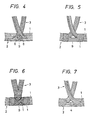
- the branching in this case is achieved by causing the resin-impregnated fiber strand 1 to be hung around the pins 8 and stretched as shown in Fig. 4.
- the fiber strands 1 are intertwined and arranged tightly at the branching points 9 of the fiber strand, i.e. the area where the ring portion 2 and the spoke portions 3 intersect.
- the steering wheel thus produced is devoid of large voids as found in conventional structures.
- the resin-impregnated fiber strand 1 of continuous fibers is wound and superposed on a suitable die (not shown) for a steering wheel to form a ring portion 2 and spoke portions 3 as illustrated in Fig. 5.
- a resin-impregnated fiber strand 1 is wound fast in a suitable number of turns around in the vicinity of each side of the intersecting area of the ring portions and the spoke portion to complete a steering wheel.
- the tying up of the branched point with the fiber strand 1 is effective particularly when it is performed concentrically in the vicinity of the branched point (intersecting area). This tying up might be advantageous when the width of the tied up area is made 0.5 to 1.5 times as large as the diameter of the ring portion, though it depends on the diameter and number of fiber strands 1 used. But this tying member need not be limited to the resin-impregnated fiber strand 1 of continuous long-staple fibers. In fact a tape or a ribbon of a prepreg such as, for example, a monodirectional prepreg tape can be employed.
- a ring portion and spoke portions are formed by winding and superposing a resin-impregnated fiber strand of continuous long-staple fibers in the same way as in Example 2. Then a resin-impregnated fiber strand 1, as shown in Fig. 6, is wound in a suitable number of turns in a mutually diagonally intersecting pattern around the branched point 9 to produce a steering wheel.
- This diagonal method of tying serves to expel air out of the branched point.
- the arrangement of fiber strand 1 in the branched point 9 all the more achieves an increase in tightness and the strength of the branched points 9 is still greater than those in Example 2. Even when a large load is exerted in a complicated manner upon the steering wheel, no separation is induced in the fiber strand 1 at the branched point 9. Thus, the steering wheel achieves high performance reliability.
Abstract
Description
- The present invention relates to a fiber-reinforced plastic (FRP) structure, and more particularly to a process for preparing a fiber reinforced plastic structure having at least one branching point such as, for example, a steering wheel core from a resin-impregnated strand of continuous long-staple fiber and to the product obtained this the method.
- In the past the steering wheels of automobiles, for example, have been produced from polyurethane resin and polypropylene resin with the objective of reducing the weight thereof. However, since steering wheels formed solely of such resins do not offer the necessary strength, such steering wheels have instead been prepared by molding the resins with iron bars or iron pipes laid skeletally within the structure as its reinforcing core. Thus, in the production of steering wheels the weight of reinforcing material is normally about 40% of the total weight of steering wheel. These steering wheels do not meet the full objective of weight reduction, with a further disadvantage being that, depending on the intensity of vibrations exerted on the wheel, the outer resin structure of the wheel may separate from the reinforcing material.
- As disclosed in the specification of British Patent Publication GB 2,004,835 A, a method has recently been described for the preparation of a shaped structure by winding a resin-impregnated fiber strand obtained by impregnating continuous long glass or carbon fibers with polyester resin or epoxy resin on a suitably shaped frame or pattern. When a steering wheel is manufactured by forming a core of a resin-impregnated fiber strand of continuous long-staple fibers in accordance with this method, the steering wheel produced has the advantage that it is of a notably light weight because the resin-impregnated fiber strand is very much lighter than iron and the problem of separation between the outer resin and the reinforcing core, because of vibration, is eliminated because the resin-impregnated fiber strand is very tightly adhesive to the molded outer resin such as polyurethane.
- When the reinforcing core for the steering wheel is prepared by the above-described method without any modification, a
large void 4 tends to form wherering position 2, on which a resin-impregnatedfiber strand 1 is wound in the circumferential direction of the wheel, and spokeportions 3, on which thesame fiber strand 1 is wound in the radial direction of the wheel, join as illustrated in FIGURE 7. When a bending stress or torsional force is exerted on thering part 2, the applied stress is concentrated on the portion of the wheel where the void is at the juncture of the spokes and the ring portion with the result that cracks can occur between the branched resin-impregnated fiber strands. When the crack is left to grow gradually, a fracture may possibly result at the joint. A need therefore continues to exist for a method 6f manufacturing a fiber-reinforced plastic structure of improved structural and strength characteristics. - Accordingly, one object of the present invention is to provide a method for preparing a fiber-reinforced plastic structure such as a steering wheel which is light in weight, exhibits excellent resistance to vibration, and has points of branching which are sufficiently strong which enables the structure to resist destruction by powerful external loads.
- Briefly, this object and other objects of the present invention as hereinafter will become more readily apparent can be attained in a process for preparing a fiber reinforced plastic structure by positioning pins at the points of branching in the structure, and repeatedly hanging and stretching a resin-impregnated strand of continuous long-staple fibers over and between said pins, thereby completing the structure.
- In another embodiment of the invention, a structure is completed by hanging and stretching a resin-impregnated strand of continuous long-staple fibers on and around a die, branching the strands thereby forming branching points in the structure, and typing up the branching points with a tying member in the vicinity of each of the branching points.
- In still another embodiment of the invention, a structure is completed by disposing pins at the location of each branching point, hanging and stretching a resin impregnated strand of continuous long-stable fibers on and between the pins, and then tying up each of the branching points with a tying member in the vicinity of each of the branching points.
- A more complete appreciation of the invention and many of the attendant advantages thereof will be readily obtained as the same becomes better undestood by reference to the following detailed description when considered in connection with the accompanying drawings, wherein:
- Figure 1 and Figure 2 are a plan view and a side view respectively illustrating the essential portion of a die used in the fiber-reinforced plastic structure of Example 1;
- Figure 3 is a cross section taken through Fig. 2 along the line III-III;
- Figures 4 through 6 are diagrams illustrating conditions in which resin-impregnated fiber strands are disposed at the branching points of the fiber reinforced plastic structures of Examples 1-3 of the present invention; and
- Figure 7 is a diagram illustrating the condition of the positioning of resin-impregnated fiber strands at the branching points of the conventional fiber reinforced resin structure.
- The term "continuous long-staple fibers" as used in the present invention indicates continuous fibers or rovings which are formed by roving. Suitable examples of continuous long-staple fibers which can be used in the present invention include glass fibers, carbon fibers, polyamide fibers, various ceramic fibers, and the like. The use of carbon fibers with high strength and high elasticity proves more advantageous than glass fibers from the viewpoint of weight reduction. In an alternative embodiment of the invention, fibers of different types may be used in combination to suit a given purpose. The thickness and the number of fibers which are used are not critical factors. Preferably, in the preparation of a given object or device a strand of about 2,000 to about 30,000 glass fibers of a diameter of 8 to 30 µm, preferably of 15 pm, or as many carbon fibers having a diameter ranging from 7 to 15 µm is advantageously used in the present invention. The resin-impregnated strand obtained by impregnating a strand of continuous fibers with resin, therefore, has a diameter in the range of a little over 1 mm to a little under 10 mm, preferably 2 to 3 mm.
- Suitable examples of the resin which are used to impregnate the continuous long-staple fibers include thermosetting resins such as epoxy resins for example, Araldite LY556, HY917J, DY070 manufactured by CIBA-GEIGY Limited, unsaturated polyester resins, phenol resins, and polycarbonate resins, and thermoplastic resins such as poly styrene resins, polyvinyl chloride resins, and polyurethane resins. These resins may be used either singly or in varying combinations. The viscosity of the resin bath during impregnation of the fiber strand should be within the range of 50 to 250 cP.
- The present invention has as an objective to increase the density of resin-impregnated fiber strands at the branching points discussed above relative to Figure 7 in order to avoid the occurrence of voids at this position by winding the resin-impregnated fiber strands taut over or between pins suitably disposed in the region or by tying up the wound strands with the same around the branching points of the aforementioned fiber strands. As a result, the resin-impregnated fiber strands are joined fast and the branching points of the fiber strands are vested with sufficiently high strength which makes separation of the fiber strands extremely difficult or, at least, retards the progress of the separation. Thus, plastic structures produced by this procedure exhibit notable improvement in durability and reliability under loads. The present invention, therefore, provides a structure such as a steering wheel which is light in weight, has excellent stability in resisting vibration, and has a sufficiently high strength.
- The members which are used as tie-up devices for fastening the branching points of the aforementioned fiber strands or the nearby portions thereof can be resin-impregnated fiber strands of continuous long-staple fibers of the same kind as or of a different kind from the continuous long-staple fibers used in the branched portions. Alternatively, a tape or ribbon of a prepreg, preferably a monodirectional prepreg can be used, for example.
- In order to provide pins at the branching points of a structure, it is most desirable to dispose, at prescribed locations at the branching points, branching guide members which are provided with stationary pins thereon. The pins which are used in the present invention are preferably suitably disposed on the branching guide members in such a manner that they enable the resin-impregnated fiber strands to be tightly arranged in a mutually entangling pattern. The number and the shape of such pins are not critically important factors. Optionally, two or more pins may be disposed in each of a plurality of paths along which the fiber strands are wound taut. In this case, by suitably disposing a plurality of pins and consequently regulating the arrangement of the resin-impregnated fiber strands within the branching guide members with the aid of the pins, the fiber strands wound and stretched in different directions can be superposed tightly within the branching guide members in an intertwined pattern and the force with which the fiber strands are bound to each other is notably increased. Thus, any external load which is applied at the branched points will be distributed throughout the entire branched structure, so that, the branched points enjoy notably enhanced strength and contribute to the improvement of strength of the structure as a whole.
- The branching guide members which are used for the above stated purpose can be parts having guiding paths through which the resin impregnated fiber-strands are hung and stretched. For example, the guide members may be a tubular member or a plate provided with grooves through which the aforementioned fiber strands can pass. Also they may be made of a metallic material or a plastic material. In the case of the steering wheel, such branching guide member may be disposed at the points where the fiber strands join in the ring portion and the spoke portions or at the boss part, and preferably it may be one with three forked paths.
- Having generally described this invention, a further understanding can be obtained by reference to certain specific examples which are provided herein for purposes of illustration only and are not intended to be limiting unless otherwise specified.
- In Figs. 1-3, 5 denotes an annular die which is used for preparing the ring portion of a steering wheel. Throughout the entire periphery of the die 5, a
winding groove 6 as illustrated in Fig. 3 is formed.Notches 7 are formed in portion of the inner side wall of the die to establish communication between thewinding groove 6 and the center side of the die. Twopins 8 are disposed in juxtaposition in thenotches 7. Strands of continuous long carbon or glass fibers obtained by roving and being impregnated with epoxy resin are annularly wound and superposed along thewinding groove 6 of the die. At the same time, the aforementioned resin-impregnated fiber strand is branched at thenotches 7, preferably alternately from the peripheral direction to the central direction of thedie 5, and at the center of thedie 5 the strand is wound on the other die to form the boss to complete the steering wheel. The branching in this case is achieved by causing the resin-impregnatedfiber strand 1 to be hung around thepins 8 and stretched as shown in Fig. 4. As a result, thefiber strands 1 are intertwined and arranged tightly at the branchingpoints 9 of the fiber strand, i.e. the area where thering portion 2 and thespoke portions 3 intersect. The steering wheel thus produced is devoid of large voids as found in conventional structures. In the product of Example 1, therefore, even when a considerable strong bending stress or torsional force is exerted on the steering wheel, separation between the joined fiber strands occurs with only great difficulty. Any separation which occurs at all is small in size and proceeds at a notably slower speed. Consequently, the branching points (intersecting parts) show remarkable improvement in strength and durability. Thepins 8 can be left within the steering wheel or they can be removed. - In this example, the resin-impregnated
fiber strand 1 of continuous fibers is wound and superposed on a suitable die (not shown) for a steering wheel to form aring portion 2 and spokeportions 3 as illustrated in Fig. 5. A resin-impregnatedfiber strand 1 is wound fast in a suitable number of turns around in the vicinity of each side of the intersecting area of the ring portions and the spoke portion to complete a steering wheel. As a result of this technique of tying, the arrangement of thefiber strand 1 at the branching point 9 (intersecting area of the ring portion and the spoke portion) gains all the more tightness and adhesion between the strands wound. As a result, the minimum load which causes separation at the points of juncture is greatly increased and the strength and durability of the branchedportion 9 are enhanced far beyond conventional levels. The tying up of the branched point with thefiber strand 1 is effective particularly when it is performed concentrically in the vicinity of the branched point (intersecting area). This tying up might be advantageous when the width of the tied up area is made 0.5 to 1.5 times as large as the diameter of the ring portion, though it depends on the diameter and number offiber strands 1 used. But this tying member need not be limited to the resin-impregnatedfiber strand 1 of continuous long-staple fibers. In fact a tape or a ribbon of a prepreg such as, for example, a monodirectional prepreg tape can be employed. - In this example, a ring portion and spoke portions are formed by winding and superposing a resin-impregnated fiber strand of continuous long-staple fibers in the same way as in Example 2. Then a resin-impregnated
fiber strand 1, as shown in Fig. 6, is wound in a suitable number of turns in a mutually diagonally intersecting pattern around thebranched point 9 to produce a steering wheel. This diagonal method of tying serves to expel air out of the branched point. As a result, the arrangement offiber strand 1 in thebranched point 9 all the more achieves an increase in tightness and the strength of the branched points 9 is still greater than those in Example 2. Even when a large load is exerted in a complicated manner upon the steering wheel, no separation is induced in thefiber strand 1 at thebranched point 9. Thus, the steering wheel achieves high performance reliability. - Having now fully described the invention, it will be apparent to one of ordinary skill in the art that many changes and modifications can be made thereto without departing from the spirit or scope of the invention as set forth herein.
Claims (14)
Applications Claiming Priority (2)
| Application Number | Priority Date | Filing Date | Title |
|---|---|---|---|
| JP134570/84 | 1984-06-29 | ||
| JP59134570A JPS6116170A (en) | 1984-06-29 | 1984-06-29 | Fiber reinforced resin construction having forked part |
Publications (3)
| Publication Number | Publication Date |
|---|---|
| EP0167120A2 true EP0167120A2 (en) | 1986-01-08 |
| EP0167120A3 EP0167120A3 (en) | 1986-04-23 |
| EP0167120B1 EP0167120B1 (en) | 1989-05-31 |
Family
ID=15131428
Family Applications (1)
| Application Number | Title | Priority Date | Filing Date |
|---|---|---|---|
| EP85107995A Expired EP0167120B1 (en) | 1984-06-29 | 1985-06-27 | A process for preparing a fiber-reinforced plastic structure having branching points |
Country Status (4)
| Country | Link |
|---|---|
| US (1) | US4749422A (en) |
| EP (1) | EP0167120B1 (en) |
| JP (1) | JPS6116170A (en) |
| DE (1) | DE3570623D1 (en) |
Cited By (2)
| Publication number | Priority date | Publication date | Assignee | Title |
|---|---|---|---|---|
| WO2011035860A1 (en) * | 2009-09-26 | 2011-03-31 | Bayerische Motoren Werke Aktiengesellschaft | Fibre composite structure |
| DE102012220288A1 (en) * | 2012-11-07 | 2014-06-12 | Bayerische Motoren Werke Aktiengesellschaft | Vehicle steering wheel made of fiber-reinforced plastic |
Families Citing this family (8)
| Publication number | Priority date | Publication date | Assignee | Title |
|---|---|---|---|---|
| JPS62123480U (en) * | 1986-01-30 | 1987-08-05 | ||
| US4821598A (en) * | 1986-11-05 | 1989-04-18 | Toyota Jidosha Kabushiki Kaisha | Steering wheel core material |
| JP3422519B2 (en) * | 1993-05-14 | 2003-06-30 | ジヤトコ株式会社 | Lockup control device for automatic transmission |
| DE29901404U1 (en) | 1999-01-27 | 1999-04-29 | Trw Automotive Safety Sys Gmbh | Motor vehicle steering wheel |
| WO2012142098A2 (en) | 2011-04-12 | 2012-10-18 | Ticona Llc | Umbilical for use in subsea applications |
| KR20140027252A (en) | 2011-04-12 | 2014-03-06 | 티코나 엘엘씨 | Composite core for electrical transmission cables |
| US10676845B2 (en) | 2011-04-12 | 2020-06-09 | Ticona Llc | Continuous fiber reinforced thermoplastic rod and pultrusion method for its manufacture |
| JP7131523B2 (en) * | 2019-10-16 | 2022-09-06 | トヨタ自動車株式会社 | module |
Citations (7)
| Publication number | Priority date | Publication date | Assignee | Title |
|---|---|---|---|---|
| US3056167A (en) * | 1958-07-16 | 1962-10-02 | Proman Inc | Mold for high strength members |
| US3362253A (en) * | 1966-03-09 | 1968-01-09 | Bendix Corp | Tension-torsion tie-bar and end fittings therefor |
| US4137354A (en) * | 1977-03-07 | 1979-01-30 | Mcdonnell Douglas Corporation | Ribbed composite structure and process and apparatus for producing the same |
| US4183261A (en) * | 1976-12-21 | 1980-01-15 | Messerschmitt-Bolkow-Blohm Gmbh | Shackle |
| JPS5591453A (en) * | 1978-12-28 | 1980-07-11 | Toyoda Gosei Co Ltd | Steering wheel |
| GB2041858A (en) * | 1979-02-23 | 1980-09-17 | Kelsey Hayes Co | improvements in and Relating to Torque Transmitting Members |
| GB2109291A (en) * | 1981-10-26 | 1983-06-02 | Kelsey Hayes Co | Making spoked wheels |
Family Cites Families (13)
| Publication number | Priority date | Publication date | Assignee | Title |
|---|---|---|---|---|
| US2878038A (en) * | 1955-06-27 | 1959-03-17 | Reinhold Engineering & Plastic | Plastic pipe bend and method for making same |
| US3056706A (en) * | 1958-07-16 | 1962-10-02 | Proman Inc | High lineal strength member and method of making same |
| FR1561120A (en) * | 1967-11-03 | 1969-03-28 | ||
| US3738885A (en) * | 1970-05-13 | 1973-06-12 | Renault Peugot | Methods of manufacturing steering wheels |
| US4183259A (en) * | 1974-08-22 | 1980-01-15 | Institut De Recherche Des Transports | Wheel structure adapted to spin at high angular velocities and method of manufacturing the same |
| JPS5847724B2 (en) * | 1975-10-16 | 1983-10-24 | ソニー株式会社 | Dengen Cairo |
| GB2004835B (en) * | 1977-09-22 | 1982-08-18 | Math F C | Cobweb structure |
| IT1111842B (en) * | 1978-02-27 | 1986-01-13 | Kelsey Hayes Co | COUPLE TRANSMISSION ELEMENT WITH SPOKES HAVING SPOKES MADE OF FIBERS |
| JPS5657576A (en) * | 1979-10-17 | 1981-05-20 | Nissan Motor Co Ltd | Steering wheel |
| FR2486047A1 (en) * | 1980-07-01 | 1982-01-08 | Commissariat Energie Atomique | METHOD FOR MANUFACTURING THREE DIMENSIONAL REVOLUTION PIECES AND MACHINE FOR CARRYING OUT SAID METHOD |
| US4378263A (en) * | 1981-01-26 | 1983-03-29 | Logan Robert M | Method and apparatus for making a composite material truss |
| EP0089809A1 (en) * | 1982-03-23 | 1983-09-28 | The British Petroleum Company p.l.c. | Method for the production of fibre reinforced articles |
| JPS59143764A (en) * | 1983-02-02 | 1984-08-17 | ケルシ−・ヘイズ・カンパニ− | Mold and manufacture for manufacturing wheel with spoke |
-
1984
- 1984-06-29 JP JP59134570A patent/JPS6116170A/en active Granted
-
1985
- 1985-06-27 DE DE8585107995T patent/DE3570623D1/en not_active Expired
- 1985-06-27 EP EP85107995A patent/EP0167120B1/en not_active Expired
- 1985-06-27 US US06/749,447 patent/US4749422A/en not_active Expired - Fee Related
Patent Citations (7)
| Publication number | Priority date | Publication date | Assignee | Title |
|---|---|---|---|---|
| US3056167A (en) * | 1958-07-16 | 1962-10-02 | Proman Inc | Mold for high strength members |
| US3362253A (en) * | 1966-03-09 | 1968-01-09 | Bendix Corp | Tension-torsion tie-bar and end fittings therefor |
| US4183261A (en) * | 1976-12-21 | 1980-01-15 | Messerschmitt-Bolkow-Blohm Gmbh | Shackle |
| US4137354A (en) * | 1977-03-07 | 1979-01-30 | Mcdonnell Douglas Corporation | Ribbed composite structure and process and apparatus for producing the same |
| JPS5591453A (en) * | 1978-12-28 | 1980-07-11 | Toyoda Gosei Co Ltd | Steering wheel |
| GB2041858A (en) * | 1979-02-23 | 1980-09-17 | Kelsey Hayes Co | improvements in and Relating to Torque Transmitting Members |
| GB2109291A (en) * | 1981-10-26 | 1983-06-02 | Kelsey Hayes Co | Making spoked wheels |
Non-Patent Citations (1)
| Title |
|---|
| PATENTS ABSTRACTS OF JAPAN, vol. 4, no. 136 (M-33) [618], 24th September 1980, page 40 M 33; & JP - A - 55 91 453 (TOYODA GOSEI K.K.) 11-07-1980 * |
Cited By (2)
| Publication number | Priority date | Publication date | Assignee | Title |
|---|---|---|---|---|
| WO2011035860A1 (en) * | 2009-09-26 | 2011-03-31 | Bayerische Motoren Werke Aktiengesellschaft | Fibre composite structure |
| DE102012220288A1 (en) * | 2012-11-07 | 2014-06-12 | Bayerische Motoren Werke Aktiengesellschaft | Vehicle steering wheel made of fiber-reinforced plastic |
Also Published As
| Publication number | Publication date |
|---|---|
| JPH031185B2 (en) | 1991-01-09 |
| EP0167120A3 (en) | 1986-04-23 |
| DE3570623D1 (en) | 1989-07-06 |
| EP0167120B1 (en) | 1989-05-31 |
| JPS6116170A (en) | 1986-01-24 |
| US4749422A (en) | 1988-06-07 |
Similar Documents
| Publication | Publication Date | Title |
|---|---|---|
| US4483729A (en) | Method of manufacturing continuous fiber reinforced plastic rims | |
| US5784926A (en) | Integral composite flywheel rim and hub | |
| US4565356A (en) | Bushing construction for a fiber reinforced plastic leaf spring | |
| EP0089809A1 (en) | Method for the production of fibre reinforced articles | |
| US4749422A (en) | Process for preparing a fiber-reinforced plastic structure having branching points | |
| KR900010144A (en) | FRP smelting structure and its manufacturing method | |
| US4627307A (en) | Fiber-reinforced plastic core material for steering wheels | |
| EP0165567B1 (en) | Method for joining a fiber-reinforced plastic structure, and wheel made by said method | |
| JP2000014843A (en) | Golf club shaft | |
| US2991210A (en) | Method of making a reinforced plastic vessel with an integral head | |
| GB2041858A (en) | improvements in and Relating to Torque Transmitting Members | |
| EP0177687B1 (en) | Method for the manufacture of a fiber reinforced resin structure | |
| KR950702903A (en) | Structural and Other Elements, and Methods of Making the Same (STRUCTURAL AND OTHER COMPONENTS, METHOD OF MANUFACTURE) | |
| US4585136A (en) | Attachment of rings to articles | |
| JPS61271167A (en) | Steering wheel core material made of fiber reinforced resin and manufacture thereof | |
| JPH0538764A (en) | Fiber reinforced resin composite tube and manufacture thereof | |
| JPH05168375A (en) | Material for fishing rod and its production | |
| JPH03161326A (en) | Pipe fitted with flange made of fiber reinforced composite material and preparation thereof | |
| JP3156130B2 (en) | Composite structural member having high bending strength and manufacturing method | |
| JPH0151585B2 (en) | ||
| JPS61242833A (en) | Manufacture of fiber-reinforced resin disc wheel | |
| JPH048068Y2 (en) | ||
| JPS62263035A (en) | Manufacture of long fiber reinforced resin steering wheel core | |
| JPH02300592A (en) | Frp made flange | |
| JPH0622947B2 (en) | FRP steering wheel core winding method |
Legal Events
| Date | Code | Title | Description |
|---|---|---|---|
| PUAI | Public reference made under article 153(3) epc to a published international application that has entered the european phase |
Free format text: ORIGINAL CODE: 0009012 |
|
| AK | Designated contracting states |
Designated state(s): DE FR GB |
|
| PUAL | Search report despatched |
Free format text: ORIGINAL CODE: 0009013 |
|
| AK | Designated contracting states |
Kind code of ref document: A3 Designated state(s): DE FR GB |
|
| 17P | Request for examination filed |
Effective date: 19860625 |
|
| 17Q | First examination report despatched |
Effective date: 19870520 |
|
| GRAA | (expected) grant |
Free format text: ORIGINAL CODE: 0009210 |
|
| AK | Designated contracting states |
Kind code of ref document: B1 Designated state(s): DE FR GB |
|
| REF | Corresponds to: |
Ref document number: 3570623 Country of ref document: DE Date of ref document: 19890706 |
|
| ET | Fr: translation filed | ||
| PLBE | No opposition filed within time limit |
Free format text: ORIGINAL CODE: 0009261 |
|
| STAA | Information on the status of an ep patent application or granted ep patent |
Free format text: STATUS: NO OPPOSITION FILED WITHIN TIME LIMIT |
|
| 26N | No opposition filed | ||
| REG | Reference to a national code |
Ref country code: GB Ref legal event code: 746 Effective date: 19940523 |
|
| REG | Reference to a national code |
Ref country code: FR Ref legal event code: D6 |
|
| PGFP | Annual fee paid to national office [announced via postgrant information from national office to epo] |
Ref country code: FR Payment date: 19980609 Year of fee payment: 14 |
|
| PGFP | Annual fee paid to national office [announced via postgrant information from national office to epo] |
Ref country code: GB Payment date: 19980618 Year of fee payment: 14 |
|
| PGFP | Annual fee paid to national office [announced via postgrant information from national office to epo] |
Ref country code: DE Payment date: 19980706 Year of fee payment: 14 |
|
| PG25 | Lapsed in a contracting state [announced via postgrant information from national office to epo] |
Ref country code: GB Free format text: LAPSE BECAUSE OF NON-PAYMENT OF DUE FEES Effective date: 19990627 |
|
| PG25 | Lapsed in a contracting state [announced via postgrant information from national office to epo] |
Ref country code: FR Free format text: THE PATENT HAS BEEN ANNULLED BY A DECISION OF A NATIONAL AUTHORITY Effective date: 19990630 |
|
| GBPC | Gb: european patent ceased through non-payment of renewal fee |
Effective date: 19990627 |
|
| PG25 | Lapsed in a contracting state [announced via postgrant information from national office to epo] |
Ref country code: DE Free format text: LAPSE BECAUSE OF NON-PAYMENT OF DUE FEES Effective date: 20000503 |
|
| REG | Reference to a national code |
Ref country code: FR Ref legal event code: ST |