EP0157537A2 - The manufacture of piston rings - Google Patents
The manufacture of piston rings Download PDFInfo
- Publication number
- EP0157537A2 EP0157537A2 EP85301909A EP85301909A EP0157537A2 EP 0157537 A2 EP0157537 A2 EP 0157537A2 EP 85301909 A EP85301909 A EP 85301909A EP 85301909 A EP85301909 A EP 85301909A EP 0157537 A2 EP0157537 A2 EP 0157537A2
- Authority
- EP
- European Patent Office
- Prior art keywords
- profile
- strip
- piston ring
- guide
- metal strip
- Prior art date
- Legal status (The legal status is an assumption and is not a legal conclusion. Google has not performed a legal analysis and makes no representation as to the accuracy of the status listed.)
- Granted
Links
Images


Classifications
-
- F—MECHANICAL ENGINEERING; LIGHTING; HEATING; WEAPONS; BLASTING
- F16—ENGINEERING ELEMENTS AND UNITS; GENERAL MEASURES FOR PRODUCING AND MAINTAINING EFFECTIVE FUNCTIONING OF MACHINES OR INSTALLATIONS; THERMAL INSULATION IN GENERAL
- F16J—PISTONS; CYLINDERS; SEALINGS
- F16J9/00—Piston-rings, e.g. non-metallic piston-rings, seats therefor; Ring sealings of similar construction
- F16J9/12—Details
-
- B—PERFORMING OPERATIONS; TRANSPORTING
- B21—MECHANICAL METAL-WORKING WITHOUT ESSENTIALLY REMOVING MATERIAL; PUNCHING METAL
- B21D—WORKING OR PROCESSING OF SHEET METAL OR METAL TUBES, RODS OR PROFILES WITHOUT ESSENTIALLY REMOVING MATERIAL; PUNCHING METAL
- B21D7/00—Bending rods, profiles, or tubes
- B21D7/08—Bending rods, profiles, or tubes by passing between rollers or through a curved die
-
- B—PERFORMING OPERATIONS; TRANSPORTING
- B21—MECHANICAL METAL-WORKING WITHOUT ESSENTIALLY REMOVING MATERIAL; PUNCHING METAL
- B21D—WORKING OR PROCESSING OF SHEET METAL OR METAL TUBES, RODS OR PROFILES WITHOUT ESSENTIALLY REMOVING MATERIAL; PUNCHING METAL
- B21D7/00—Bending rods, profiles, or tubes
- B21D7/12—Bending rods, profiles, or tubes with programme control
Definitions
- the invention relates to the manufacture of piston rings and, in particular, piston rings for internal combustion engines.
- Piston rings for internal combustion engines are commonly formed of metal in a generally circular profile with two free ends closely adjacent one another (but not touching). Each piston ring is received in an associated groove provided in a piston for the internal combustion engine, where the purpose of the ring is to provide a seal between the piston and an associated cylinder or liner.
- the piston ring should seal against the associated cylinder or liner with an even pressure all round the piston ring, the outward pressing force being provided either by natural resilience of the piston ring and/or by an independent spring, possibly assisted by gas pressure behind the piston ring.
- the piston ring is required to provide this even pressure when at an elevated operating temperature.
- the profile of the piston ring at room temperature will not be the same as the shape of the piston ring at these operating temperatures since the expansion of the piston ring will not be uniform around its circumference because of the presence of the free ends.
- a piston will have two or more piston rings arranged at axially spaced positions and so there will be a difference between the temperatures at which the various rings operate, and consequently the amount of expansion will differ between these various piston rings.
- each piston ring must, when cold, have a predetermined non-circular profile which is such as to ensure that, on expansion, the piston ring gives the required even outward pressure at its particular operating temperature.
- this profile is an oval shape with the maximum diameter in a direction normal to the plane containing the gap and the piston ring axis and with the ends of the piston ring directed inwardly towards one another. If a certain "mean" such profile is assumed, piston rings operating in a hotter environment will generally have the ends directed further in towards one another, so-called “negative ovality", and piston rings operating in a cooler environment will have their ends directed inwardly less than the mean, a so-called "positive ovality".
- Piston rings can be produced by a number of methods.
- One such method is by bending a metal strip into a required profile, by the use of cam-controlled rollers, and then separating the profile so produced to form piston rings.
- a machine for performing such a method is described in French Patent Specification No.2517226 where the profile of the piston ring is determined by a cam whose shape is transferred to the steel strip by a cam-follower and a pair of rollers whose position adjusts to vary the curvature imparted to the steel strip.
- Cams have the advantage that they can allow very high rates of production of piston rings. For example, the production of piston rings using cams is much quicker than other conventional methods of production of piston rings such as casting a cylinder of material, cutting the cylinder in planes normal to the axis thereof and then finish machining the rings so produced. Thus the use of cams to bend strips has found wide application in the production of piston rings.
- cams have, however, a number of disadvantages.
- a different cam is required for each profile of piston ring and, as explained above, many different profiles of piston ring are needed.
- cams are subject to wear and so there can be a loss of accuracy due to such wear and a need to replace cams at regular intervals.
- a fresh cam must be produced each time a new profile of piston ring is required and these cams must be machined to a very high accuracy. Thus it is not possible to vary the profile of a piston ring quickly and easily.
- a machine for producing from a metal strip, piston rings of a predetermined profile for internal combustion engines comprising at least two guides for guiding the metal strip in a path in which the strip is formed by the guides into a generally circular profile, which is then separated from the remainder of the strip to form a piston ring, characterised in that at least one of said guides is movable relatively to the other guide or guides during said formation of a piston ring to vary the profile of the strip around the piston ring, and a control system for producing digital signals corresponding to a required piston ring profile, the digital signals controlling the movement of said at least one movable guide during formation of a piston ring from said metal strip to produce a piston ring having the required profile therearound.
- the piston rings are produced from a flat strip of a suitable metal.
- a steel strip may be used having a composition which is 1% chromium, 1% molybdenum, 0.55% nickel and 0.1% vanadium (all by weight), remainder iron and having a hardness of 500-550 on the Vickers scale.
- a second material for the strip is a low alloy steel or plain eutectoid carbon steel treated by a patenting process in which a strip of the steel is transformed from an austenitic structure to a finely and uniformly dispersed ferrite-cementite structure in a molten lead or salt bath and then hard drawn through dies.
- the strip It is required to form the strip into a piston ring of generally circular profile having two free ends separated by a gap.
- the precise profile of the ring will vary from ring to ring but in general it will be oval with the longer ax,is normal to the plane including the gap and the piston ring axis.
- the ends of the ring will be directed inwardly by a required amount, in order to produce a ring which, when at its individual operating temperature, and under the particular imposed loads encountered by such a piston ring, applies a uniform pressure to the associated cylinder or liner.
- a piston ring having this shape can be produced from a steel strip by bending the steel strip into a ring, with the curvature imparted to the strip being varied around the ring in such a way as to produce the required ring profile.
- These variations are very small; for example, the difference between the major and minor axes of the shape may only be 1 or 2 mm.
- a pair of fixed driven rollers 10.a, 10b which engage the same side of the strip 11 at spaced positions therealong.
- the strip 11 is pulled past the rollers 10 by drive rollers 55.
- a movable roller 12 engages the strip 11 on the opposite side thereof to the fixed rollers 10 and intermediate the fixed driver rollers 10.
- the rollers 10 impart a constant curvature to the strip 11.
- the movable roller 12 has its axis parallel to the axes of the fixed rollers 10 and is mounted at one end of an arm 13, whose other end is mounted for pivotal movement about an axis parallel to the roller axes. As seen in Figure 1, the movable roller 12 is positioned so that the strip 11 is bent by the roller 12, the degree of curvature being determined by the position of the movable roller 12 in relation to the fixed rollers 10.
- the position of the movable roller 12 is controlled by pivoting of the arm 13 by an actuator 14 which is fed with signals by a control system.
- the actuator 14 may take any convenient form such as linear motor, a solenoid, a low-inertia high-torque motor or a device operating on magnetostrictive effects or any transducer device for converting electrical signals into movement of the arm 13.
- the control system is a digital control system and can take a number of forms.
- it could be a conventional numerical control or computer numerical control device in which information defining required roller positions at various points around the circumference of a piston ring is fed into a computer store and is read in real time to provide electric signals for the actuator 14 which cause the actuator 14 to move the arm 13 to the required positions.
- feedback may be provided.
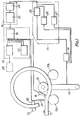
- the control system comprises a computer 15, a signal processor 16 and an arm control system 17.
- An end detector 18 feeds to the computer a signal when an end of the strip is detected at a datum point and a strip velocity detector 21 feeds the computer a signal representative of the strip velocity (and thus representative of the position of the strip 11 relative to the datum).
- input profile data is prepared which defines the required curvature of the piston ring at a succession of spaced positions around the ring.
- This data does not give all the positions of the movable roller 12 around the ring, but gives only, for example, points at which the curvature changes or points at which the curvature changes non-linearly.
- the profile may, for example, be defined at intervals around the piston ring as drops or decreases from a nominal maximum curvature.
- the piston ring is to be symmetrical about one or more planes including the axis of the piston ring, it is only necessary to define the input data for the initial symmetrical portion.
- the piston ring is to be generally oval with a longer axis normal to the plane including the piston ring axis and the gap and is to have inwardly directed ends, only input data for the first half of the piston ring need be defined, because the other half of the piston ring is the same.
- the profile data is fed to an input device 18 of the computer 15 and passes from the input device 18 to a store 19 of the computer 15.
- the computer 15 may be a microprocessor.
- the strip 11 is set in movement and the end detector 20 and the strip velocity transducer 21 feed to the store 19 in real time a digital signal when the end of the strip passes a datum point, and a signal representative of the position of the strip 11 relative to the datum (and thus relative to the movable roller 12).
- the computer 15 On receipt of these signals, the computer 15 produces a group of bits corresponding to the required roller position at the point on the strip 11 contacted by the roller 12 at that moment in time; the required position being the roller position necessaryy to produce the required piston ring profile at that point.
- the computer 15 does this in the following way. If the strip is defined by 2000 bits of information and is moving at 0.3 metres per second, then, for a piston ring of 100 mm "diameter", and if the position could be required to be changed every 10 minutes of arc, the computer must produce a group of bits every 500 microseconds. Of course, at high speeds and more complex profiles, this time interval may be less than that, for example, it may be 100 microseconds.
- a calculating unit 22 of the computer calculates, before the commencement of strip movement, a few initial groups of bits from the input data held in the store 19 and passes these initial groups to the store 19, from which the initial groups are outputted to the signal processor 16, described in more detail below. During the remainder of the 500 microsecond intervals between the groups, the calculating unit 22 produces groups of bits for subsequent future roller positions. The number of groups so produced depends on the time available within each interval and the capacity of the store 19 to hold such groups.
- the production of these groups from the input data will involve interpolation between the input data, because the groups may be required at intervals which are smaller than the intervals at which the input data is given.
- the interpolation is preferably a linear interpolation, although it will be appreciated that the computer could be programmed to produce any other required interpolation.
- the computer 15 will be programmed to produce groups for the whole circumferential profile of the piston ring, even where the input data defines only a portion of a symmetrical profile.
- the output from the computer 15 is thus a succession of groups of bits defining successive roller positions and produced in real time at time intervals determined by signals from the transducer 21.
- This succession of groups of bits is received by a digital-to-analogue converter 23 of the signal processor 16 which converts each of the succession of groups into a roller arm position signal of constant amplitude corresponding to the value of the associated group of bits.
- the duration of each such signal is the same as the interval between successive groups.
- This output which is effectively a series of consecutive steps, is fed to a step converter 24 of the signal processor 16.
- the step converter 24 the amplitude of each signal is stored until the next succeeding signal is received.
- the step converter 24 outputs a continuous signal which has an initial value equal to the value of the first received signal and has a final value equal to the value of the next successive signal.
- the continuous signal will rise or fall progressively between these initial and final values. This rise or fall may be linear but need not necessarily be so.
- the output of the step converter 24 is thus a continuous signal which so changes progressively that at successive time intervals equal to the time intervals of the digital signals, the amplitude of the signal is related to the successive values of the digital signals.
- This continuous signal can thus be regarded as an analogue of the succession of roller arm position signals representing the required position of the roller at a succession of points around the piston ring.
- This continuous signal is fed as an input signal to a feedback control device 25 of the closed-loop continuous arm control system 17.
- the output of the feedback control device 25 is fed to the actuator 14 which moves the arm 13 in accordance with the output signal.
- the output of the actuator 14 is monitored by an arm position transducer 26 and an arm speed transducer 27 which provide feedback arm position and arm velocity signals to the feedback control device 25 which uses these feedback signals to modify the continuous signal from the signal processor 16 in accordance with the feedback signals.
- the computer 15 does not have to deal with the feedback control of the arm positioning signal. This is done in a purely analogue fashion in a closed-loop control system. This is another factor which allows the computer to be a microprocessor which maintains high strip speeds and allows complex changes of arm position.
- step converter 24 produces a time delay in the system. A further time delay is introduced by the inertia of the roller 12 and the associated arm 13 (although this will be kept to a minimum).
- the computer 15 may be programmed so that the datum position from which the roller position signals are calculated, is offset by a distance equal to the time lag in the system. This will bring the profile into the required spatial orientation.
- the computer 15 can be quickly and simply programmed to produce any required workpiece profile. Indeed, by the provision of a keyboard, shown in chain dotted line at 28, it is possible to alter the profiles of the piston rings during production.
- the first two rollers, 10a and 11 could be the fixed driven rollers and the third roller 10.b, could be the movable roller.
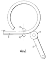
- a pair of fixed driven rollers 10 which engage on opposite sides of the strip 11 and serve to drive and guide the strip 11 towards a movable roller 12. These two rollers 10 do not impart any curvature to the strip 11; they simply form fixed guides.
- the movable roller 12 is aranged as described above with reference to Figure 1 and is connected to a control system of any of the kinds described above with reference to Figure 1.
- the machine of Figure 3 is a variation of the machine of Figure 2 in which there are two movable rollers 12a and 12b. These rollers engage on either side of the strip and have their centres arranged on a line which intersects the line passing through the axes of the fixed rollers 10, the point of intersection defining the centre about which the strip is curved by the movable rollers 12a, 12b, so that pivoting of the arm 13 increases or decreases this curvature.
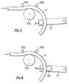
- rollers 30a, 30b, 30c, 30d there are four rollers 30a, 30b, 30c, 30d, with fixed axes before the movable roller 12 mounted on the arm 13.
- These fixed rollers are arranged in an initial group of three; two of which, 30a, 30b of smaller diameter, contact the strip 11 on one side at spaced positions therealong and the other of which 30c, of larger diameter, contacts the strip 11 on the other side thereof, at a point intermediate the points of contact of the two smaller diameter rollers 30a, 30b.
- the arrangement of these three rollers is such that the strip is given an initial curvature which is the minimum required curvature.
- the driven roller 12 only needs to apply to the strip, variations in curvature relative to this maximum curvature.
- the three initial rollers 30.a, 30b, 30c may be driven to advance the steel strip.
- the fourth roller 30d is arranged. It has the same diameter as the smaller diameter initial rollers 30a, 30h, and contacts the strip on the side thereof opposite to the side contacted by the movable roller 12 to guide the strip 11 onto the movable roller 12.
- the fourth fixed roller 30d is omitted and -a single movable roller 12 is provided which contacts the strip on the opposite side to the side contacted by the movable roller of the embodiment of Figure 4.
- the initial rollers 30a, 30b, 30c are arranged to give the strip a maximum curvature with the movable roller 12 imparting to the strip a variable increase in this curvature.
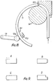
- FIG. 6 The variation shown in Figure 6 is generally the same as that of Figure 5 except that there are two movable rollers 12.a, 12b arranged similarly to the movable rollers in the embodiment of Figure 3.
- the initial rollers will give the strip 11 a fixed curvature that is intermediate the maximum and minimum required curvatures, the movable rollers 12a, 12h imparting to the strip a variable increase in this curvature.
- the strip 11 is initially fed through a curved passage formed between a fixed member 31 and a roller 32 whose axis is fixed.
- the passage is a similar cross-section to the cross-section of the strip 11 and at the outlet a die 33 is provided, whose purpose will be described in more detail below.
- a further roller 34 having a fixed axis is provided just before the movable roller 12 which is mounted on an arm 13 in the manner described above.
- two such movable rollers may be provided, as in the embodiments of Figures 2 and 4.
- the die 33 in the embodiments of both Figure 7 and Figure 8, is arranged such as to alter the cross-section of the strip to a required piston ring cross-section.
- Some possible cross-sections are shown in Figure 9.
- section A the width of the piston ring is reduced by the die.
- section B the inner edges of the piston ring are tapered - although both edges are shown tapered, only one of the edges may be so tapered.
- section C the outer edge of the ring is barrelled in order to provide improved lubrication over the ring edge during operation.
- a rebate is formed around one inner edge of the piston ring.
- the strip 11 is fed by two rollers, one of which is shown at 40.
- the strip 11 then engages two fixed guides 41, 42 arranged on opposite sides of the strip 11 and at spaced positions therealong. These guides 41, 42 impart no curvature to the strip 11.
- an adjustable guide 43 which imparts a fixed curvature to the strip 11 during operation of the machine, but which can be adjusted between operations to alter this imparted curvature. This curvature is the maximum curvature that is required.
- the strip 11 next contacts the strip length encoder 44 which, similarly to the strip velocity detector 21 in the Figure 1 embodiment, produces a signal representative of the length of the strip 11 which has passed the encoder.
- a solenoid indenter 45 is then provided for marking the strip 11 at a predetermined point therealong.
- a movable roller 46 then contacts the strip 11 on the opposite side of the strip 11 to the adjustable guide 43.
- the roller 46 is mounted eccentrically on a shaft 47 which is rotated by an actuator (not shown) controlled by a control system which may be of the kind described above with reference to Figure 1.
- the rotation of the shaft 47 causes the roller 46 to vary the curvature already imparted by the adjustable guide 43 in accordance with the required piston ring profile data fed to the control system.
- a sensor 48 acts in the same way as the arm position transducer 26 of the Figure 1 embodiment, to provide a feedback signal representative of the position of the roller 46.
- rollers may, where appropriate, be replaced by suitable guides, or the guides may, where appropriate, be replaced by suitable rollers.
- the piston rings may be separated from the strip in a number of ways.
- One possibility is to halt the feed of the strip 11 when the ring has been formed and then cut the ring from the remaining strip using, for example, a grinding wheel.
- a number of rings may be formed in succession in a helical coil which is then cut along its length to form the individual rings and to form the gaps between the ends of the rings.
- the rings can be treated, for example, by nitro-carburising before being used.
Abstract
Description
- The invention relates to the manufacture of piston rings and, in particular, piston rings for internal combustion engines.
- Piston rings for internal combustion engines are commonly formed of metal in a generally circular profile with two free ends closely adjacent one another (but not touching). Each piston ring is received in an associated groove provided in a piston for the internal combustion engine, where the purpose of the ring is to provide a seal between the piston and an associated cylinder or liner.
- For this purpose, the piston ring should seal against the associated cylinder or liner with an even pressure all round the piston ring, the outward pressing force being provided either by natural resilience of the piston ring and/or by an independent spring, possibly assisted by gas pressure behind the piston ring. It will be appreciated that the piston ring is required to provide this even pressure when at an elevated operating temperature. The profile of the piston ring at room temperature will not be the same as the shape of the piston ring at these operating temperatures since the expansion of the piston ring will not be uniform around its circumference because of the presence of the free ends. Further, a piston will have two or more piston rings arranged at axially spaced positions and so there will be a difference between the temperatures at which the various rings operate, and consequently the amount of expansion will differ between these various piston rings.
- As a result of this, each piston ring must, when cold, have a predetermined non-circular profile which is such as to ensure that, on expansion, the piston ring gives the required even outward pressure at its particular operating temperature. In general, this profile is an oval shape with the maximum diameter in a direction normal to the plane containing the gap and the piston ring axis and with the ends of the piston ring directed inwardly towards one another. If a certain "mean" such profile is assumed, piston rings operating in a hotter environment will generally have the ends directed further in towards one another, so-called "negative ovality", and piston rings operating in a cooler environment will have their ends directed inwardly less than the mean, a so-called "positive ovality".
- Piston rings can be produced by a number of methods. One such method is by bending a metal strip into a required profile, by the use of cam-controlled rollers, and then separating the profile so produced to form piston rings. A machine for performing such a method is described in French Patent Specification No.2517226 where the profile of the piston ring is determined by a cam whose shape is transferred to the steel strip by a cam-follower and a pair of rollers whose position adjusts to vary the curvature imparted to the steel strip.
- Cams have the advantage that they can allow very high rates of production of piston rings. For example, the production of piston rings using cams is much quicker than other conventional methods of production of piston rings such as casting a cylinder of material, cutting the cylinder in planes normal to the axis thereof and then finish machining the rings so produced. Thus the use of cams to bend strips has found wide application in the production of piston rings.
- The use of a cam has, however, a number of disadvantages. First, a different cam is required for each profile of piston ring and, as explained above, many different profiles of piston ring are needed. In addition, cams are subject to wear and so there can be a loss of accuracy due to such wear and a need to replace cams at regular intervals. Further, a fresh cam must be produced each time a new profile of piston ring is required and these cams must be machined to a very high accuracy. Thus it is not possible to vary the profile of a piston ring quickly and easily.
- According to the invention, there is provided a machine for producing from a metal strip, piston rings of a predetermined profile for internal combustion engines, comprising at least two guides for guiding the metal strip in a path in which the strip is formed by the guides into a generally circular profile, which is then separated from the remainder of the strip to form a piston ring, characterised in that at least one of said guides is movable relatively to the other guide or guides during said formation of a piston ring to vary the profile of the strip around the piston ring, and a control system for producing digital signals corresponding to a required piston ring profile, the digital signals controlling the movement of said at least one movable guide during formation of a piston ring from said metal strip to produce a piston ring having the required profile therearound.
- The following is a more detailed description of some embodiments of the invention, by way of example, reference being made to the accompanying drawings in which:-
- Figure 1 is a schematic view of a first form of machine for producing piston rings from a metal strip and including two fixed rollers, a movable roller, and a control system,
- Figure 2 is a schematic view of a second form of machine for producing piston rings from a metal strip and including two feed rollers and a movable roller,
- Figure 3 is a schematic view of a third form of machine for producing piston rings from a metal strip and including two feed rollers and two movable rollers for imparting curvature to the strip,
- Figure 4 is a schematic view of a fourth form of machine for producing piston rings from a metal strip and including four rollers for imparting a constant curvature to a metal strip and a single movable roller for imparting a variable curvature to the strip,
- Figure 5 is a schematic view of a first variation of the machine of Figure 4,
- Figure 6 is a schematic view of a second variation of the embodiment of Figure 4,
- Figure 7 is a schematic view of a fifth form of machine for producing piston rings from a metal strip, having a passageway for the metal strip formed by a roller and a fixed member, there being a die at the outlet of the fixed member, a free guide roller and a movable roller for imparting a variable curvature to the strip,
- Figure 8 is a schmematic view of a sixth form of a machine for producing piston rings from a metal strip which is similar to the machine for Figure 7 but has two movable rollers,
- Figure 9 shows four alternative cross-sections of piston ring produced by using the machines of Figures 6 and 7, and
- Figure 10 is a schematic view of a seventh form of a machine for producing piston rings from a metal strip and having two guides, an adjustable guide and a movable roller for imparting a variable curvature to the strip.
- In all the embodiments, the piston rings are produced from a flat strip of a suitable metal. For example, a steel strip may be used having a composition which is 1% chromium, 1% molybdenum, 0.55% nickel and 0.1% vanadium (all by weight), remainder iron and having a hardness of 500-550 on the Vickers scale. A second material for the strip is a low alloy steel or plain eutectoid carbon steel treated by a patenting process in which a strip of the steel is transformed from an austenitic structure to a finely and uniformly dispersed ferrite-cementite structure in a molten lead or salt bath and then hard drawn through dies.
- It is required to form the strip into a piston ring of generally circular profile having two free ends separated by a gap. The precise profile of the ring will vary from ring to ring but in general it will be oval with the longer ax,is normal to the plane including the gap and the piston ring axis. The ends of the ring will be directed inwardly by a required amount, in order to produce a ring which, when at its individual operating temperature, and under the particular imposed loads encountered by such a piston ring, applies a uniform pressure to the associated cylinder or liner. These profiles can be readily calculated.
- It will be appreciated that a piston ring having this shape can be produced from a steel strip by bending the steel strip into a ring, with the curvature imparted to the strip being varied around the ring in such a way as to produce the required ring profile. These variations are very small; for example, the difference between the major and minor axes of the shape may only be 1 or 2 mm.
- The purpose of the machines now to be described with reference to the drawings is to impart such a variable curvature to the strip to give the strip a precalculated profile.
- Referring now firstly to Figure 1, in the first machine, there are provided a pair of fixed driven rollers 10.a, 10b which engage the same side of the
strip 11 at spaced positions therealong. Thestrip 11 is pulled past therollers 10 bydrive rollers 55. Amovable roller 12 engages thestrip 11 on the opposite side thereof to thefixed rollers 10 and intermediate thefixed driver rollers 10. Therollers 10 impart a constant curvature to thestrip 11. - The
movable roller 12 has its axis parallel to the axes of thefixed rollers 10 and is mounted at one end of anarm 13, whose other end is mounted for pivotal movement about an axis parallel to the roller axes. As seen in Figure 1, themovable roller 12 is positioned so that thestrip 11 is bent by theroller 12, the degree of curvature being determined by the position of themovable roller 12 in relation to thefixed rollers 10. The position of themovable roller 12 is controlled by pivoting of thearm 13 by anactuator 14 which is fed with signals by a control system. Theactuator 14 may take any convenient form such as linear motor, a solenoid, a low-inertia high-torque motor or a device operating on magnetostrictive effects or any transducer device for converting electrical signals into movement of thearm 13. - The control system is a digital control system and can take a number of forms. For example, it could be a conventional numerical control or computer numerical control device in which information defining required roller positions at various points around the circumference of a piston ring is fed into a computer store and is read in real time to provide electric signals for the
actuator 14 which cause theactuator 14 to move thearm 13 to the required positions. In order to ensure the correct positioning of the roller, feedback may be provided. - For more complex shapes and for faster production, it may be desirable to employ the control system shown in Figure 1. The control system comprises a
computer 15, asignal processor 16 and anarm control system 17. Anend detector 18 feeds to the computer a signal when an end of the strip is detected at a datum point and a strip velocity detector 21 feeds the computer a signal representative of the strip velocity (and thus representative of the position of thestrip 11 relative to the datum). - Prior to the production of piston rings, input profile data is prepared which defines the required curvature of the piston ring at a succession of spaced positions around the ring. This data does not give all the positions of the
movable roller 12 around the ring, but gives only, for example, points at which the curvature changes or points at which the curvature changes non-linearly. The profile may, for example, be defined at intervals around the piston ring as drops or decreases from a nominal maximum curvature. Of course, where the piston ring is to be symmetrical about one or more planes including the axis of the piston ring, it is only necessary to define the input data for the initial symmetrical portion. For example, where the piston ring is to be generally oval with a longer axis normal to the plane including the piston ring axis and the gap and is to have inwardly directed ends, only input data for the first half of the piston ring need be defined, because the other half of the piston ring is the same. - The profile data is fed to an
input device 18 of thecomputer 15 and passes from theinput device 18 to astore 19 of thecomputer 15. Thecomputer 15 may be a microprocessor. - The
strip 11 is set in movement and the end detector 20 and the strip velocity transducer 21 feed to thestore 19 in real time a digital signal when the end of the strip passes a datum point, and a signal representative of the position of thestrip 11 relative to the datum (and thus relative to the movable roller 12). - On receipt of these signals, the
computer 15 produces a group of bits corresponding to the required roller position at the point on thestrip 11 contacted by theroller 12 at that moment in time; the required position being the roller position necesary to produce the required piston ring profile at that point. Thecomputer 15 does this in the following way. If the strip is defined by 2000 bits of information and is moving at 0.3 metres per second, then, for a piston ring of 100 mm "diameter", and if the position could be required to be changed every 10 minutes of arc, the computer must produce a group of bits every 500 microseconds. Of course, at high speeds and more complex profiles, this time interval may be less than that, for example, it may be 100 microseconds. Since thestore 19 cannot, in practice, store all the bits required to define the complete profile of the workpiece, a calculatingunit 22 of the computer calculates, before the commencement of strip movement, a few initial groups of bits from the input data held in thestore 19 and passes these initial groups to thestore 19, from which the initial groups are outputted to thesignal processor 16, described in more detail below. During the remainder of the 500 microsecond intervals between the groups, the calculatingunit 22 produces groups of bits for subsequent future roller positions. The number of groups so produced depends on the time available within each interval and the capacity of thestore 19 to hold such groups. - It will be appreciated that the production of these groups from the input data will involve interpolation between the input data, because the groups may be required at intervals which are smaller than the intervals at which the input data is given. In this case, the interpolation is preferably a linear interpolation, although it will be appreciated that the computer could be programmed to produce any other required interpolation. In addition, the
computer 15 will be programmed to produce groups for the whole circumferential profile of the piston ring, even where the input data defines only a portion of a symmetrical profile. - It will also be appreciated that, since not all future groups are calculated before the commencement of machining, the
store 19 does not require a substantial capacity and thestore 19 found in current microprocessors will in most cases be adequate. - The output from the
computer 15 is thus a succession of groups of bits defining successive roller positions and produced in real time at time intervals determined by signals from the transducer 21. This succession of groups of bits is received by a digital-to-analogue converter 23 of thesignal processor 16 which converts each of the succession of groups into a roller arm position signal of constant amplitude corresponding to the value of the associated group of bits. The duration of each such signal is the same as the interval between successive groups. - This output, which is effectively a series of consecutive steps, is fed to a
step converter 24 of thesignal processor 16. In thestep converter 24, the amplitude of each signal is stored until the next succeeding signal is received. As soon as the amplitude of the next succeeding signal has been established, thestep converter 24 outputs a continuous signal which has an initial value equal to the value of the first received signal and has a final value equal to the value of the next successive signal. Plainly, if there is a difference in amplitude between the two successive signals, the continuous signal will rise or fall progressively between these initial and final values. This rise or fall may be linear but need not necessarily be so. - The output of the
step converter 24 is thus a continuous signal which so changes progressively that at successive time intervals equal to the time intervals of the digital signals, the amplitude of the signal is related to the successive values of the digital signals. This continuous signal can thus be regarded as an analogue of the succession of roller arm position signals representing the required position of the roller at a succession of points around the piston ring. - This continuous signal is fed as an input signal to a
feedback control device 25 of the closed-loop continuousarm control system 17. The output of thefeedback control device 25 is fed to theactuator 14 which moves thearm 13 in accordance with the output signal. The output of theactuator 14 is monitored by anarm position transducer 26 and anarm speed transducer 27 which provide feedback arm position and arm velocity signals to thefeedback control device 25 which uses these feedback signals to modify the continuous signal from thesignal processor 16 in accordance with the feedback signals. - Thus, the
computer 15 does not have to deal with the feedback control of the arm positioning signal. This is done in a purely analogue fashion in a closed-loop control system. This is another factor which allows the computer to be a microprocessor which maintains high strip speeds and allows complex changes of arm position. - The operation of the
step converter 24 produces a time delay in the system. A further time delay is introduced by the inertia of theroller 12 and the associated arm 13 (although this will be kept to a minimum). In order to ensure that the spatial orientation of the profile is correct, thecomputer 15 may be programmed so that the datum position from which the roller position signals are calculated, is offset by a distance equal to the time lag in the system. This will bring the profile into the required spatial orientation. - It will be appreciated that the
computer 15 can be quickly and simply programmed to produce any required workpiece profile. Indeed, by the provision of a keyboard, shown in chain dotted line at 28, it is possible to alter the profiles of the piston rings during production. - It will be appreciated that, in the embodiments of Figure 1, the first two rollers, 10a and 11, could be the fixed driven rollers and the third roller 10.b, could be the movable roller.
- The embodiments of the remaining Figures are controlled in the same way as the embodiment of Figure 1. Accordingly, the control of these embodiments will not be described. In addition, these embodiments have features in common with the embodiment of Figure 1 and these features common to Figure 1 and to the Figures of the remaining embodiments will be given the same reference numerals and will not be described in detail.
- In the machine of Figure 2, there are provided a pair of fixed driven
rollers 10 which engage on opposite sides of thestrip 11 and serve to drive and guide thestrip 11 towards amovable roller 12. These tworollers 10 do not impart any curvature to thestrip 11; they simply form fixed guides. Themovable roller 12 is aranged as described above with reference to Figure 1 and is connected to a control system of any of the kinds described above with reference to Figure 1. - The machine of Figure 3, is a variation of the machine of Figure 2 in which there are two
movable rollers rollers 10, the point of intersection defining the centre about which the strip is curved by themovable rollers arm 13 increases or decreases this curvature. - The use of the two rollers 12.a, 12b gives improved control over the variation of the curvature of the piston ring. Referring next to Figure 4, in this embodiment, there are four
rollers movable roller 12 mounted on thearm 13. These fixed rollers are arranged in an initial group of three; two of which, 30a, 30b of smaller diameter, contact thestrip 11 on one side at spaced positions therealong and the other of which 30c, of larger diameter, contacts thestrip 11 on the other side thereof, at a point intermediate the points of contact of the twosmaller diameter rollers roller 12 only needs to apply to the strip, variations in curvature relative to this maximum curvature. The three initial rollers 30.a, 30b, 30c may be driven to advance the steel strip. - Just before the movable roller, the
fourth roller 30d is arranged. It has the same diameter as the smaller diameterinitial rollers 30a, 30h, and contacts the strip on the side thereof opposite to the side contacted by themovable roller 12 to guide thestrip 11 onto themovable roller 12. - In the variation of the Figure 4 embodiment shown in
- Figure 5, the fourth fixed
roller 30d is omitted and -a singlemovable roller 12 is provided which contacts the strip on the opposite side to the side contacted by the movable roller of the embodiment of Figure 4. In this case, theinitial rollers movable roller 12 imparting to the strip a variable increase in this curvature. - The variation shown in Figure 6 is generally the same as that of Figure 5 except that there are two movable rollers 12.a, 12b arranged similarly to the movable rollers in the embodiment of Figure 3. In this case, the initial rollers will give the strip 11 a fixed curvature that is intermediate the maximum and minimum required curvatures, the
movable rollers 12a, 12h imparting to the strip a variable increase in this curvature. - Referring next to Figure 7, in this embodiment the
strip 11 is initially fed through a curved passage formed between a fixedmember 31 and aroller 32 whose axis is fixed. The passage is a similar cross-section to the cross-section of thestrip 11 and at the outlet adie 33 is provided, whose purpose will be described in more detail below. Afurther roller 34 having a fixed axis is provided just before themovable roller 12 which is mounted on anarm 13 in the manner described above. - As shown in Figure 8, two such movable rollers may be provided, as in the embodiments of Figures 2 and 4.
- The
die 33, in the embodiments of both Figure 7 and Figure 8, is arranged such as to alter the cross-section of the strip to a required piston ring cross-section. Some possible cross-sections are shown in Figure 9. In section A, the width of the piston ring is reduced by the die. In section B, the inner edges of the piston ring are tapered - although both edges are shown tapered, only one of the edges may be so tapered. - In section C, the outer edge of the ring is barrelled in order to provide improved lubrication over the ring edge during operation. In section D, a rebate is formed around one inner edge of the piston ring.
- Referring next to Figure 10, in this machine the
strip 11 is fed by two rollers, one of which is shown at 40. Thestrip 11 then engages two fixedguides strip 11 and at spaced positions therealong. These guides 41, 42 impart no curvature to thestrip 11. Next, in the path of travel of thestrip 11, there is anadjustable guide 43 which imparts a fixed curvature to thestrip 11 during operation of the machine, but which can be adjusted between operations to alter this imparted curvature. This curvature is the maximum curvature that is required. thestrip 11 next contacts thestrip length encoder 44 which, similarly to the strip velocity detector 21 in the Figure 1 embodiment, produces a signal representative of the length of thestrip 11 which has passed the encoder. Asolenoid indenter 45 is then provided for marking thestrip 11 at a predetermined point therealong. - A
movable roller 46 then contacts thestrip 11 on the opposite side of thestrip 11 to theadjustable guide 43. Theroller 46 is mounted eccentrically on ashaft 47 which is rotated by an actuator (not shown) controlled by a control system which may be of the kind described above with reference to Figure 1. The rotation of theshaft 47 causes theroller 46 to vary the curvature already imparted by theadjustable guide 43 in accordance with the required piston ring profile data fed to the control system. Asensor 48 acts in the same way as thearm position transducer 26 of the Figure 1 embodiment, to provide a feedback signal representative of the position of theroller 46. - It will be appreciated that, in any of the embodiments described above, the rollers may, where appropriate, be replaced by suitable guides, or the guides may, where appropriate, be replaced by suitable rollers.
- In all the embodiments described above with reference to the drawings, the piston rings may be separated from the strip in a number of ways. One possibility is to halt the feed of the
strip 11 when the ring has been formed and then cut the ring from the remaining strip using, for example, a grinding wheel. Alternatively, a number of rings may be formed in succession in a helical coil which is then cut along its length to form the individual rings and to form the gaps between the ends of the rings. - Subsequent to formation of the rings, they can be treated, for example, by nitro-carburising before being used.
Claims (10)
Applications Claiming Priority (2)
| Application Number | Priority Date | Filing Date | Title |
|---|---|---|---|
| GB848407712A GB8407712D0 (en) | 1984-03-24 | 1984-03-24 | Piston rings for ic engines |
| GB8407712 | 1984-03-24 |
Publications (4)
| Publication Number | Publication Date |
|---|---|
| EP0157537A2 true EP0157537A2 (en) | 1985-10-09 |
| EP0157537A3 EP0157537A3 (en) | 1986-10-29 |
| EP0157537B1 EP0157537B1 (en) | 1989-02-08 |
| EP0157537B2 EP0157537B2 (en) | 1992-03-11 |
Family
ID=10558642
Family Applications (1)
| Application Number | Title | Priority Date | Filing Date |
|---|---|---|---|
| EP85301909A Expired - Lifetime EP0157537B2 (en) | 1984-03-24 | 1985-03-19 | The manufacture of piston rings |
Country Status (6)
| Country | Link |
|---|---|
| EP (1) | EP0157537B2 (en) |
| JP (1) | JP2568997B2 (en) |
| KR (1) | KR920008668B1 (en) |
| CA (1) | CA1259172A (en) |
| DE (1) | DE3568144D1 (en) |
| GB (2) | GB8407712D0 (en) |
Cited By (13)
| Publication number | Priority date | Publication date | Assignee | Title |
|---|---|---|---|---|
| EP0348837A2 (en) * | 1988-06-30 | 1990-01-03 | T&N TECHNOLOGY LIMITED | Method for the manufacture of piston rings |
| EP0360115A2 (en) * | 1988-09-19 | 1990-03-28 | T&N TECHNOLOGY LIMITED | Improvements in and relating to piston rings |
| WO1990006459A1 (en) * | 1988-12-01 | 1990-06-14 | Hepworth & Grandage Limited | Piston rings |
| EP0405600A1 (en) * | 1989-06-30 | 1991-01-02 | Hashimoto Forming Industry Co., Ltd. | Method and apparatus for bending manufacturing of long workpiece |
| FR2652290A1 (en) * | 1989-09-25 | 1991-03-29 | Riken Kk | OIL SCRAPER SEGMENT ASSEMBLY AND ITS MANUFACTURING AND MACHINING METHOD. |
| FR2678853A1 (en) * | 1991-07-09 | 1993-01-15 | Lorraine Laminage | Method and device for controlling an operation of bending long metallurgical products |
| GB2264886A (en) * | 1992-03-11 | 1993-09-15 | T & N Technology Ltd | Manufacture of piston rings |
| DE4225878A1 (en) * | 1992-08-05 | 1994-02-10 | Bayer Isolierglasfab Kg | Bending of e.g. insulated glass panels, to form circular or part circular bend - using distance holder section which is displaced longitudinally and displacement path measured using light barrier |
| DE4416258A1 (en) * | 1994-05-07 | 1995-11-16 | Ae Goetze Gmbh | Appts. for production of non-circular piston rings |
| US5752705A (en) * | 1988-12-01 | 1998-05-19 | Ae Piston Products Limited | Piston rings |
| CN100344405C (en) * | 2004-09-20 | 2007-10-24 | 南京飞燕活塞环股份有限公司 | Method for machining steel piston ring by using profiling rod |
| CN100500365C (en) * | 2001-07-03 | 2009-06-17 | 金井宏彰 | Method and device for producing grip ring of pipe joint and grip ring for pipe joint |
| CN111957865A (en) * | 2020-08-08 | 2020-11-20 | 宁波东艾密封科技有限公司 | Manufacturing process and application of large-sized sealing gasket metal framework welding-free technology |
Families Citing this family (6)
| Publication number | Priority date | Publication date | Assignee | Title |
|---|---|---|---|---|
| GB2283555A (en) * | 1993-11-04 | 1995-05-10 | Ford Motor Co | Piston ring seal |
| US5946961A (en) * | 1998-05-01 | 1999-09-07 | Buhrke Industries, Inc. | Web bowing apparatus |
| DE102005041408A1 (en) * | 2005-09-01 | 2007-03-08 | Mahle International Gmbh | Method for producing a piston ring for internal combustion engines and such a piston ring |
| JP4981081B2 (en) * | 2009-03-11 | 2012-07-18 | 株式会社栗本鐵工所 | Bending roll device |
| ITRM20090430A1 (en) * | 2009-08-06 | 2011-02-07 | Cml Int Spa | METHOD OF MEASUREMENT OF LENGTH OF EXTRADOSSO OR INTRADOSIS CURVE TRACES OF A STRETCHED PIECE AND ITS MEASURING INSTRUMENT |
| CN112222850B (en) * | 2020-09-23 | 2021-08-03 | 常州汉诺车圈有限公司 | Automatic fixed-length cutting forming machine |
Citations (8)
| Publication number | Priority date | Publication date | Assignee | Title |
|---|---|---|---|---|
| FR1145975A (en) * | 1955-08-12 | 1957-11-05 | Sealing segment, process for its manufacture and installation for the implementation of this process | |
| CH354651A (en) * | 1956-12-06 | 1961-05-31 | H Dr Ing Berg Heinz | Machine for the automatic production of non-round piston rings |
| GB1138860A (en) * | 1966-04-16 | 1969-01-01 | Ralph Gordon Smith | Improvements in the bending of structural members |
| DE1948805A1 (en) * | 1968-09-26 | 1970-06-25 | A T Richardson & Sons Propriet | Method and device for producing ring-shaped blanks for toothed rims and other ring-shaped components |
| DE2551944A1 (en) * | 1974-11-20 | 1976-05-26 | Boeing Co | Numerically controlled shaping machine - particularly using shaping rolls controlled by numerical programme |
| DE2838128A1 (en) * | 1978-09-01 | 1980-03-06 | Goetze Ag | Rolled wire piston ring prodn. machine - has wire fed between rollers to non-circular forming roller and support roll |
| FR2517226A1 (en) * | 1981-11-30 | 1983-06-03 | Floquet Monopole | Piston ring manufacturing method - has steel strip undergoing first and second bending operations to vary radius, controlled by cam |
| EP0088576B1 (en) * | 1982-03-04 | 1986-05-28 | British United Shoe Machinery Limited | Methods and apparatus for manufacturing cutting tools |
Family Cites Families (7)
| Publication number | Priority date | Publication date | Assignee | Title |
|---|---|---|---|---|
| GB856254A (en) * | 1956-03-14 | 1960-12-14 | Bochumer Ges Fur Grubenausbau | A new or improved method and apparatus for the production of supporting segments |
| JPS5217818B2 (en) * | 1973-04-19 | 1977-05-18 | ||
| US3854215A (en) * | 1973-07-27 | 1974-12-17 | Boeing Co | Multiplanar sensor and control system for use in roll forming machines |
| US4080815A (en) * | 1975-06-09 | 1978-03-28 | The Boeing Company | Pinch and forming roll assembly for numerically controlled contour forming machines |
| JPS522717A (en) * | 1975-06-24 | 1977-01-10 | Nec Corp | Method of manufacturing magnetic head |
| JPS5659532A (en) * | 1979-10-23 | 1981-05-23 | Nippon Steel Corp | Method and apparatus for manufacturing spiral pipe |
| JPS5725233A (en) * | 1980-07-18 | 1982-02-10 | Nhk Spring Co Ltd | Formation of coil spring |
-
1984
- 1984-03-24 GB GB848407712A patent/GB8407712D0/en active Pending
-
1985
- 1985-03-19 DE DE8585301909T patent/DE3568144D1/en not_active Expired
- 1985-03-19 EP EP85301909A patent/EP0157537B2/en not_active Expired - Lifetime
- 1985-03-19 GB GB08507025A patent/GB2155828A/en not_active Withdrawn
- 1985-03-23 KR KR1019850001908A patent/KR920008668B1/en not_active IP Right Cessation
- 1985-03-25 CA CA000477407A patent/CA1259172A/en not_active Expired
- 1985-03-25 JP JP60058656A patent/JP2568997B2/en not_active Expired - Lifetime
Patent Citations (8)
| Publication number | Priority date | Publication date | Assignee | Title |
|---|---|---|---|---|
| FR1145975A (en) * | 1955-08-12 | 1957-11-05 | Sealing segment, process for its manufacture and installation for the implementation of this process | |
| CH354651A (en) * | 1956-12-06 | 1961-05-31 | H Dr Ing Berg Heinz | Machine for the automatic production of non-round piston rings |
| GB1138860A (en) * | 1966-04-16 | 1969-01-01 | Ralph Gordon Smith | Improvements in the bending of structural members |
| DE1948805A1 (en) * | 1968-09-26 | 1970-06-25 | A T Richardson & Sons Propriet | Method and device for producing ring-shaped blanks for toothed rims and other ring-shaped components |
| DE2551944A1 (en) * | 1974-11-20 | 1976-05-26 | Boeing Co | Numerically controlled shaping machine - particularly using shaping rolls controlled by numerical programme |
| DE2838128A1 (en) * | 1978-09-01 | 1980-03-06 | Goetze Ag | Rolled wire piston ring prodn. machine - has wire fed between rollers to non-circular forming roller and support roll |
| FR2517226A1 (en) * | 1981-11-30 | 1983-06-03 | Floquet Monopole | Piston ring manufacturing method - has steel strip undergoing first and second bending operations to vary radius, controlled by cam |
| EP0088576B1 (en) * | 1982-03-04 | 1986-05-28 | British United Shoe Machinery Limited | Methods and apparatus for manufacturing cutting tools |
Non-Patent Citations (1)
| Title |
|---|
| LECTURE NOTES IN ECONOMICS AND MATHEMATICAL SYSTEMS, Z}rich, CH, 19th-22nd March 1974, vol. 94, pages 88-98, Springer-Verlag, Berlin, DE; E. TROSTMANN et al.: "Numerically controlled bending of metal beams" * |
Cited By (19)
| Publication number | Priority date | Publication date | Assignee | Title |
|---|---|---|---|---|
| EP0348837A3 (en) * | 1988-06-30 | 1990-09-05 | T&N Technology Limited | Method for the manufacture of piston rings |
| EP0348837A2 (en) * | 1988-06-30 | 1990-01-03 | T&N TECHNOLOGY LIMITED | Method for the manufacture of piston rings |
| EP0360115A2 (en) * | 1988-09-19 | 1990-03-28 | T&N TECHNOLOGY LIMITED | Improvements in and relating to piston rings |
| EP0360115A3 (en) * | 1988-09-19 | 1990-08-22 | T&N TECHNOLOGY LIMITED | Improvements in and relating to piston rings |
| WO1990006459A1 (en) * | 1988-12-01 | 1990-06-14 | Hepworth & Grandage Limited | Piston rings |
| US5752705A (en) * | 1988-12-01 | 1998-05-19 | Ae Piston Products Limited | Piston rings |
| US5425257A (en) * | 1989-06-30 | 1995-06-20 | Hashimoto Forming Industry Co., Ltd. | Method and apparatus for bending an elongate workpiece |
| EP0405600A1 (en) * | 1989-06-30 | 1991-01-02 | Hashimoto Forming Industry Co., Ltd. | Method and apparatus for bending manufacturing of long workpiece |
| FR2652290A1 (en) * | 1989-09-25 | 1991-03-29 | Riken Kk | OIL SCRAPER SEGMENT ASSEMBLY AND ITS MANUFACTURING AND MACHINING METHOD. |
| FR2678853A1 (en) * | 1991-07-09 | 1993-01-15 | Lorraine Laminage | Method and device for controlling an operation of bending long metallurgical products |
| GB2264886A (en) * | 1992-03-11 | 1993-09-15 | T & N Technology Ltd | Manufacture of piston rings |
| GB2264886B (en) * | 1992-03-11 | 1995-05-03 | T & N Technology Ltd | Manufacture of piston rings |
| US5502880A (en) * | 1992-03-11 | 1996-04-02 | T&N Technology Limited | Manufacture of piston rings |
| DE4225878A1 (en) * | 1992-08-05 | 1994-02-10 | Bayer Isolierglasfab Kg | Bending of e.g. insulated glass panels, to form circular or part circular bend - using distance holder section which is displaced longitudinally and displacement path measured using light barrier |
| DE4416258A1 (en) * | 1994-05-07 | 1995-11-16 | Ae Goetze Gmbh | Appts. for production of non-circular piston rings |
| CN100500365C (en) * | 2001-07-03 | 2009-06-17 | 金井宏彰 | Method and device for producing grip ring of pipe joint and grip ring for pipe joint |
| CN100344405C (en) * | 2004-09-20 | 2007-10-24 | 南京飞燕活塞环股份有限公司 | Method for machining steel piston ring by using profiling rod |
| CN111957865A (en) * | 2020-08-08 | 2020-11-20 | 宁波东艾密封科技有限公司 | Manufacturing process and application of large-sized sealing gasket metal framework welding-free technology |
| CN111957865B (en) * | 2020-08-08 | 2022-07-01 | 宁波东艾密封科技有限公司 | Manufacturing process and application of large-sized sealing gasket metal framework welding-free technology |
Also Published As
| Publication number | Publication date |
|---|---|
| EP0157537B2 (en) | 1992-03-11 |
| EP0157537B1 (en) | 1989-02-08 |
| DE3568144D1 (en) | 1989-03-16 |
| CA1259172A (en) | 1989-09-12 |
| EP0157537A3 (en) | 1986-10-29 |
| KR850007008A (en) | 1985-10-30 |
| JP2568997B2 (en) | 1997-01-08 |
| GB8507025D0 (en) | 1985-04-24 |
| KR920008668B1 (en) | 1992-10-08 |
| GB2155828A (en) | 1985-10-02 |
| JPS60216926A (en) | 1985-10-30 |
| GB8407712D0 (en) | 1984-05-02 |
Similar Documents
| Publication | Publication Date | Title |
|---|---|---|
| CA1259172A (en) | Manufacture of piston rings | |
| US4080815A (en) | Pinch and forming roll assembly for numerically controlled contour forming machines | |
| CA1219662A (en) | Machine tool control | |
| SU651673A3 (en) | Method of working internal and external surfaces of polygonal workpieces | |
| CN1599197A (en) | Iron core and method of manufacturing the same and apparatus for manufacturing the same | |
| US4416130A (en) | Pulsing impact straightener | |
| EP0610510B1 (en) | Method of radial forging of blank | |
| EP0001326A1 (en) | A rotatable sleeve for guiding a web of wire strands | |
| US3688540A (en) | Tube rolling mill employing a tapered mandrel and a cluster of rolls that each have specially designed tube contacting grooves | |
| US3842635A (en) | Tube rolling mill for producing tubing with various external configurations | |
| US4937937A (en) | Method for the manufacture of piston rings | |
| US5068963A (en) | Piston rings | |
| JP2553447B2 (en) | Processing method and device in swaging machine | |
| GB1260695A (en) | Apparatus and method for winding coil springs | |
| JP2002066678A (en) | Manufacturing method of spiral corrugated wire | |
| US3726117A (en) | Device and method for controlling the movement of a deformation roll | |
| SU1532120A1 (en) | Method of straightening unrigid shafts | |
| Patel et al. | A review on innovation of wire straightening cutting machine | |
| SU891220A1 (en) | Method of dimension adjusting of two cutting tools | |
| SU995921A1 (en) | Method of rolling wedge-shaped sections | |
| SU1759574A1 (en) | Method of obtaining gear profiles by geometric plotting of evolvent | |
| CA1242870A (en) | Tool actuators for machine tools | |
| JPH06218728A (en) | Strand cutter | |
| SU1560353A1 (en) | Arrangement for straightening wire | |
| RU2030931C1 (en) | Method of adjusting trio screw rolling mill |
Legal Events
| Date | Code | Title | Description |
|---|---|---|---|
| PUAI | Public reference made under article 153(3) epc to a published international application that has entered the european phase |
Free format text: ORIGINAL CODE: 0009012 |
|
| AK | Designated contracting states |
Designated state(s): DE FR IT SE |
|
| PUAL | Search report despatched |
Free format text: ORIGINAL CODE: 0009013 |
|
| AK | Designated contracting states |
Kind code of ref document: A3 Designated state(s): DE FR IT SE |
|
| 17P | Request for examination filed |
Effective date: 19870313 |
|
| 17Q | First examination report despatched |
Effective date: 19880114 |
|
| GRAA | (expected) grant |
Free format text: ORIGINAL CODE: 0009210 |
|
| AK | Designated contracting states |
Kind code of ref document: B1 Designated state(s): DE FR IT SE |
|
| REF | Corresponds to: |
Ref document number: 3568144 Country of ref document: DE Date of ref document: 19890316 |
|
| ET | Fr: translation filed | ||
| ITF | It: translation for a ep patent filed |
Owner name: MODIANO & ASSOCIATI S.R.L. |
|
| PLBI | Opposition filed |
Free format text: ORIGINAL CODE: 0009260 |
|
| 26 | Opposition filed |
Opponent name: GOETZE AG Effective date: 19891103 |
|
| PUAH | Patent maintained in amended form |
Free format text: ORIGINAL CODE: 0009272 |
|
| STAA | Information on the status of an ep patent application or granted ep patent |
Free format text: STATUS: PATENT MAINTAINED AS AMENDED |
|
| 27A | Patent maintained in amended form |
Effective date: 19920311 |
|
| AK | Designated contracting states |
Kind code of ref document: B2 Designated state(s): DE FR IT SE |
|
| ET3 | Fr: translation filed ** decision concerning opposition | ||
| ITF | It: translation for a ep patent filed |
Owner name: MODIANO & ASSOCIATI S.R.L. |
|
| ITTA | It: last paid annual fee | ||
| EAL | Se: european patent in force in sweden |
Ref document number: 85301909.9 |
|
| PGFP | Annual fee paid to national office [announced via postgrant information from national office to epo] |
Ref country code: FR Payment date: 20010208 Year of fee payment: 17 |
|
| PGFP | Annual fee paid to national office [announced via postgrant information from national office to epo] |
Ref country code: DE Payment date: 20010222 Year of fee payment: 17 |
|
| PGFP | Annual fee paid to national office [announced via postgrant information from national office to epo] |
Ref country code: SE Payment date: 20010223 Year of fee payment: 17 |
|
| PG25 | Lapsed in a contracting state [announced via postgrant information from national office to epo] |
Ref country code: SE Free format text: LAPSE BECAUSE OF NON-PAYMENT OF DUE FEES Effective date: 20020320 |
|
| PG25 | Lapsed in a contracting state [announced via postgrant information from national office to epo] |
Ref country code: DE Free format text: LAPSE BECAUSE OF NON-PAYMENT OF DUE FEES Effective date: 20021001 |
|
| EUG | Se: european patent has lapsed |
Ref document number: 85301909.9 |
|
| PG25 | Lapsed in a contracting state [announced via postgrant information from national office to epo] |
Ref country code: FR Free format text: LAPSE BECAUSE OF NON-PAYMENT OF DUE FEES Effective date: 20021129 |
|
| REG | Reference to a national code |
Ref country code: FR Ref legal event code: ST |