EP0140859A2 - A method and a device for bending a wire into a zigzag shape - Google Patents
A method and a device for bending a wire into a zigzag shape Download PDFInfo
- Publication number
- EP0140859A2 EP0140859A2 EP84850327A EP84850327A EP0140859A2 EP 0140859 A2 EP0140859 A2 EP 0140859A2 EP 84850327 A EP84850327 A EP 84850327A EP 84850327 A EP84850327 A EP 84850327A EP 0140859 A2 EP0140859 A2 EP 0140859A2
- Authority
- EP
- European Patent Office
- Prior art keywords
- wire
- point
- engagement
- arm
- holding member
- Prior art date
- Legal status (The legal status is an assumption and is not a legal conclusion. Google has not performed a legal analysis and makes no representation as to the accuracy of the status listed.)
- Withdrawn
Links
Images

Classifications
-
- B—PERFORMING OPERATIONS; TRANSPORTING
- B21—MECHANICAL METAL-WORKING WITHOUT ESSENTIALLY REMOVING MATERIAL; PUNCHING METAL
- B21F—WORKING OR PROCESSING OF METAL WIRE
- B21F1/00—Bending wire other than coiling; Straightening wire
- B21F1/04—Undulating
Definitions
- the arm 16, with its distal end with respect to the bearing 13, is pivotally mounted by means of a bearing 32 at the end of an additional arm 17 the opposite end of which is mounted on the frame by means of a bearing 33 at a distance from the bearing 14 of the arm 11 that corresponds to the distance between the bearings 13, 32 of the arm 16, and the distance between the bearings 32, 33 of the arm 17 corresponds to the distance between the bearings 13, 14 of the arm 11.
- the arms 11, 16 and 17 form a parallelogrammatic arrangement.
Abstract
A wire (10) is bent into a zigzag shape by being clamped at two spaced-apart points while a hook (20) engages a point of the wire midway between the two points and pulls the wire against an abutment (31). One of the points is thereafter displaced linearly towards the other point while the hook and the abutment (31) are being pivoted in a circular arc with the other point as centre of pivotment.
Description
- The present invention relates to a method for bending a wire into a zigzag shape and a device for carrying out the method.
- It is considerably more difficult than one can imagine to bend a wire into an accurate zigzag shape. The reason for this is that if the bending of a wire turning point deviates ever so little from the bending of the preceding one, the error will be accumulated and the zigzag shape will become skew or irregular, or an arcuate zigzag formation is obtained instead of a straight one. Such an exact zigzag shape is thus not obtainable'by the commonest bending technique, namely that using wheels with zigzag-shaped peripheries engaging each other.
- The object of the present invention is to provide a method for bending a wire into a zigzag shape in a simple and reliable way and at a high speed without any risk of imperfect bends. According to the invention, this method is achieved in that the wire is held clamped at a first and a second point which are spaced apart, that an engagement member is caused to engage the wire at a third point midway between said points and to pull it into engagement with an abutment by a force which is less than the clamping force at said first and second points, that said second point is displaced linearly towards said first point through a distance which is related to the distance between the turning points of the zigzag shape to be produced, under pivotment of third point with the first point serving as centre of pivotment, a complete bending being performed at the first and third points whereas only half a bending at the second point, and that the wire is thereafter fed, such that the half bend is placed at the first point for completion during the next bending cycle.
- A suitable device for automatically bending a wire into a zigzag shape has a first wire holding member which is movable in and out of the path of movement of the wire to be bent, a second wire holding member which is linearly movable a predetermined distance towards and away from said first wire holding member, a member for engaging the wire midway between the points of engagement of said first and second wire holding members by a force which is less than the force of retention of the first and second wire holding members, means for displacing the second wire holding member towards the first wire holding member in synchronism with a displacement of the wire engaging member in an arcuate path with the point of engagement of the first wire holding member serving as centre, whereby the wire will be completely bent at the points of engagement of the first wire holding member and the engagement member and half bent at the point of engagement of the second wire holding member, a reciprocating element for intermittently feeding the wire such a distance that the point where the wire is half bent is placed in the first wire holding member, and a frame supporting all of said components and having guide means for the wire.
- An advantageous embodiment of the invention is characterised in that a first adjusting device is connected to the wire feeding means for changing the wire feeding distance during operation, that a second adjusting device is connected to the second wire holding member to cause it to engage the wire at a point whose spacing from and distance of displacement towards the point of engagement of the first wire holding member corresponds to the adjusted wire feeding distance, and that a third adjusting device is adapted to change the point of engagement of the wire engaging member with the wire, such that it is constantly located midway between the points of engagement of the wire holding members.
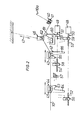
- The invention will be described in greater detail hereinbelow with reference to the accompanying drawings, which highly schematically illustrate an embodiment of the invention and in which Fig. 1 is a top plan view of a device for bending a wire with a constant spacing between the turning points of the zigzag shape, while Fig. 2 similarly shows a modified embodiment of the device for bending a wire into a zigzag shape with increasing or decreasing width.
- In the drawings, 10 designates a straight wire, for instance of a diameter of 8-10 mm, which is bent into a zigzag shape by means of the illustrated device, as shown at 10a. The machine for bending the wire has two
link arms bearing 13. Thefirst arm 11 is pivotally mounted by means of a bearing 14 on a frame (not shown). Similarly, the other end of the second arm is pivotally mounted by means of abearing 15 on an element 30 which is linearly displaceable towards and away from the other end of thefirst arm 11, as appears from the drawing. Afurther arm 16 is connected to thearms arm 16, with its distal end with respect to thebearing 13, is pivotally mounted by means of abearing 32 at the end of anadditional arm 17 the opposite end of which is mounted on the frame by means of abearing 33 at a distance from the bearing 14 of thearm 11 that corresponds to the distance between thebearings arm 16, and the distance between thebearings arm 17 corresponds to the distance between thebearings 13, 14 of thearm 11. Thus, thearms - The
arms jaws clamping jaw 21 of the first arm is displaceable, by means of a piston andcylinder assembly 23, at right angles to the plane of movement of the arm towards and away from an abutment connected to the frame at a point directly above the bearing of thearm 11 to clamp the wire and release it after the bending operation, while the clampingjaw 22 of the other arm is displaceable in the plane of movement of the arm towards and away from an abutment mounted on the frame concentrically with thebearing 15 of the arm, by means of a piston andcylinder assembly 24. Preferably, theclamping jaw 21 and its abutment are mounted on a supporting device pivotally adjustable on the frame in the plane of movement of thearm 11. Thejaw 21 operates at right angles to the path of movement of the arm in order that it should be removable from the path of movement of thebent wire 10 when the wire should be advanced, as will be more fully explained hereinbelow. A piston andcylinder assembly 18 is mounted on thearm 16 and connected by acoupling 19 to ahook 20 which, by means of said piston and cylinder assembly, can be raised and lowered and pulled in the direction of a bearing housing and anabutment 31 in order, when in the lowered position, to draw thewire 10 against the surface of the abutment which is facing the wire and which is bevelled towards the centre from the vertical side edges. - A
feeding device 25 is adapted to engage thewire 10 by means of ajaw assembly 26 which is brought into and out of engagement with thewire 10 by means of a piston and cylinder assembly, to feed it a predetermined distance. The feeding device is reciprocating in the longitudinal direction of thewire 10 with the aid of a piston andcylinder assembly 28. - The device described above operates in the following manner when used for bending a
wire 10 into azigzag shape 10a. It is assumed that the formation illustrated to the right in the drawing has previously been performed and that the machine is in the starting position for a new bending operation with thearms cylinder assemblies wire 10 against the pertaining abutment. At the same time, the piston andcylinder assembly 18 is activated, whereby thehook 20 is lowered over the wire and pulled with the wire against theabutment 31 where the wire is prebent because of the centrally directed bevel of the abutment surface and the shanks of the zigzag formation are stretched. When the piston andcylinder assembly 29 is activated, the element 30, which supports said other end of thearm 12, is pulled linearly towards said other end of thearm 11. As clearly appears from the drawing, thearms arm 17 is so mounted on the frame that it extends in parallel with thearm 11 and since the bearings of thearm 17 are spaced the same distance from each other as those of thearm 11, the parallelogrammatic arrangement is obtained which during the movement of the arms maintains thearm 16 on a line which is an extension of the bisector of the angle formed by thearms clamping jaws cylinder assembly 18, such that thehook 20 can be extracted (by being resilient) a certain distance, about 5 mm, when theassembly 18 starts to pull. In actual practice, it has proved suitable that thejaws clamping jaw 21 and at thehook 20, are complete whereas only half a bend has been achieved at theclamping jaw 22. The piston andcylinder assembly 29 is thereafter deactivated and thejaws hook 20, are released by deactivation of the pertaining piston and cylinder assemblies. The hook is thereafter lifted out of its engagement with the wire which has now been bent. During the bending operation, the feed device has been moved to the left in the drawing out of its engagement with thewire 10, and after thejaws hook 20 have been released, the piston andcylinder assembly 27 is activated, such that thejaw assembly 26 is clamped about the wire, whereupon the piston andcylinder assembly 28 is activated for moving thewire 10 to the right in the drawing such a distance that the wire portion half bent in thejaw 22 is placed in thejaw 21. As earlier mentioned, thejaw 21 is removed from the path of movement of the wire, such that it may move freely in the direction of feed. During the movement of thewire 10, the piston andcylinder assembly 29 is activated for returning thearms clamping jaw 22, now in position in theclamping jaw 21. - Fig. 2 shows a modified embodiment of the invention which is intended for making zigzag shapes with increasing and/or decreasing width, for instance for use as webs in beams with increasing and/or decreasing spacings between the flanges. To make it possible to produce such zigzag formations, means must be provided for changing the wire lengths which are fed and thereafter bent, which means that the feed device must be adjustable, like the limits of the reciprocating movement of the proximal clamping jaw with respect to the feed device. Moreover, the point of engagement of the hook engaging the wire midway between the clamping jaws must be so adjustable that the hook will always engage the wire at the correct point. A device for carrying out this process is illustrated in Fig. 2.
- In Fig. 2, 40 designates a clamping jaw corresponding to the
clamping jaw 21 in Fig. 1 and being displaceable upwardly and downwardly in the vertical direction by means of a piston andcylinder assembly 41 in the same.manner and for the same purpose as theclamping jaw 21. Anelement 42 equipped with aclamping jaw 43 and corresponding to the element 30 is provided, like afeed device 44 withclamping jaws 45. 46 designates a hook device for engaging thewire 10 midway between the points of engagement of theclamping jaws device 47 for operating it may be designed in the manner shown in Fig. 1, and arms corresponding to thearms clamping jaws 40 and 43 and that the force of engagement of the hook device is less than the force by which theclamping jaws 40, 43 engage thewire 10, as in the previous embodiment. - In order to change the length of wire which is fed and thereafter bent, two motors 48 and 49 (Fig. 2) are provided which are each connected to a
shaft 50 and 51, respectively. The first shaft 50 has a first threadedportion 52 and a second threaded portion 53. Thesecond shaft 51 has a first threadedportion 54 and a second threadedportion 55. The two threaded portions of the first shaft 50 and the first threaded portion of thesecond shaft 51 consist of threads of the same pitch while the second threadedportion 55 of theshaft 51 consists of a thread with but half said pitch. Anabutment 56 with a threaded throughhole is disposed on the first threadedportion 52 of the first shaft 50. Similarly,abutments 58 and 59 with threaded throughholes are disposed on the first threaded portion '54 of the second shaft and on the second threaded portion 53 of the first shaft, respectively. - The
feed device 44 has aprojection 63 of shorter length and aprojection 64 of greater length. As appears from the figure, theshorter projection 63 of the feed device engages afixed abutment 57 in its forward position while thelonger projection 64 engages anabutment 56 in the rear position of the feed device. By rotation of the shaft 50 and, hence, of the threadedportion 52, the position of theabutment 56 is changed and, in this way, it is easy to change the range of the distance within which thefeed device 44 is moving, such that wire portions of different lengths can be fed. Similarly, themovable element 42 has ashorter projection 65 and alonger projection 66, theshorter projection 65 engaging theabutment 58 on the first threaded portion of the second arm when theelement 42 is in its position to the left in the figure while thelonger projection 66 engages the abutment 59 on the second threaded portion 53 of the first arm when theelement 42 is in its end position to the right in the figure. This ensures that theelement 42 is displaced a distance which corresponds to the extended or shortened wire length fed by thefeed device 44. Naturally, the hook device 46 must also be adjusted to the adjusted wire length, which in the instant is effected by means of aguide member 61 having arounded entrance ramp 62. Theguide member 61 has a protrudinglug 60 with a threaded throughhole which engages the second threaded portion of the second shaft. Themember 61 should be moved but half the distance as compared with thefeed device 44 and for this reason the thread of the threadedportion 55 has but half the pitch as compared with the other threadedportions element 42 has started to move towards the clamping jaw 40 and the engagement device 46 has left themember 61. Thus, theabutment 58 and thelug 60 are displaced a predetermined distance in anticipation of the next bending cycle. When bending has been effected and theelement 42 starts its movement to the left, the motor 48 is activated, which is of the same type as the motor 49, whereby theabutments 56 and 59 are moved the desired distance. In order to interrupt the movement of theelements feed device 44 and theelement 42 with the clampingjaw 43, as in the previous embodiment, are displaced during the feeding and wire bending operations, respectively, by means of piston and cylinder assemblies of the same type as described above. However, it is of course also conceivable to have theshafts 50, 51 with the threaded portions directly engage theelements abutments 56 and 59 are always moved over equally long distances in the same direction, for which reason they may be interconnected. - In the foregoing, the
wire 10 has been regarded as a rigid, unresilient body but a certain degree of resilience will of course always exist. This will however not affect the method of bending or the apparatus per se. However, regard should be paid when setting the apparatus. - The schematic figures of the drawings are primarily intended to illustrate the novel bending principle, and it goes without saying that, in actual practice, the machine has a number of components which are not shown in the drawings, for instance a straightening device before the
feed device 25 and control means controlling the supply of fluid to the different piston and cylinder assemblies, such that these are activated in the correct order.
Claims (11)
1. A method for bending a wire (10) into a zigzag shape (10a), characterised in that the wire (10) is held clamped at a first and a second point which are spaced apart, that an engagement member (20) is caused to engage the wire at a third point midway between said points and to pull it into engagement with an abutment (31) by a force which is less than the clamping force at said first and second points, that said second point is displaced linearly towards said first point through a distance which is related to the distance between the turning points of the zigzag shape to be produced, under pivotment of said third point with the first point serving as centre of pivotment, a complete bending being performed at said first and third points whereas only half a bending at the second point, and that the wire is thereafter fed, such that the half bend is placed at the first point for completion during the next bending cycle.
2. Method as claimed in claim 1, charac- terised in that the engagement member (20) pulls the wire into engagement with an abutment (31) forming an angle in the plane of bending, such that the wire (10) is prebent on either side of the point of engagement of said engagement member (20) at the same time as a tractive force is exerted in the wire portions between the point of engagement of the engagement member and the first and second points.
3. Method as claimed in claim 1 or 2, in which the width of the zigzag shape is continuously increased or decreased, e.g. for use of the wire as a web in beams with increasing and decreasing spacings, respectively, between the flanges, characterised in that the wire (10) is fed a distance which exceeds or falls below the preceding feeding distance, and that the position and distance of displacement of said second point of engagement, like the point of engagement of the engagement member (20), are adjusted in correspondence with the change of the feeding distance.
4. A device for automatically bending a wire (10) into a zigzag shape (10a), character- ised by a first wire holding member (21) which is movable in and out of the path of movement of the wire (10) to be bent, a second wire holding member (22) which is linearly movable a predetermined distance towards and away from said first wire holding member (21), a member (20) for engaging the wire (10) midway between the points of engagement of said first and second wire holding members (21 and 22, respectively) by a force which is less than the force of retention of the first and second wire holding members (21 and 22, respectively), means (29) for displacing the second wire holding member (22) towards the first wire holding member (21) in synchronism with a displacement of the wire engaging member (20) in an arcuate path with the point of engagement of the first wire holding member (21) serving as centre, whereby the wire will be completely bent at the points of engagement of the first wire holding member and the engagement member and half bent at the point of engagement of the second wire holding member, a reciprocating element (25) for intermittently feeding the wire (10) such a distance that the point where the wire is half bent is placed in the first wire holding member (21), and a frame supporting all of said components and having guide means for the wire.
5. Device as claimed in claim 4, charac- terised in that a first and a second link arm (11 and 12, respectively) are pivotally interconnected at a first end, said first arm (11), at its opposite end, being pivotally mounted on the frame concentrically with the point of engagement of the first wire holding member (21) and said second arm (12), at its opposite end, being pivotally mounted on an element (30) which is guided on said frame and linearly displaceable towards and away from said opposite end of the first arm (11), and which also supports said second wire holding member (22) with the point of engagement thereof concentric with the bearing of said arm, and that the wire engaging member (20) is disposed at the point where the arms (11, 12) are pivotally interconnected.
6. Device as claimed in claim 5, charac- terised in that the wire holding member (21) at said opposite end of the first arm (11) consists of a.hydraulic clamping jaw acting at right angles to the plane of movement of the arm (11) against an abutment on the frame, while the wire holding member (22) at said opposite end of the second arm (12) consists of a hydraulic clamping jaw acting in a plane parallel to the plane of movement of the arm (12), also against an abutment on the frame.
7. Device as claimed in claim 4 or 5, cha- racterised in that the wire engaging member (20) is mounted on a third arm (16) one end of which is pivotally mounted in the bearing (13) by means of which the first and second arms are pivotally interconnected, and the other end of which is pivotally mounted adjacent one end of a fourth arm (17) the opposite end of which is pivotally mounted on the frame at a distance from the location of the bearing (14) at said opposite end of the first arm (11), corresponding to the distance between the bearings of the third arm (16).
8. Device as claimed in claim 6, charac- terised in that the wire engaging member (20) on the third arm (16) consists of a raisable and lowerable hook which is connected to a piston and cylinder assembly (18) by means of a shaft which extends centrally through a bearing housing (31) whose surface facing the bearing of the first and second arms (11, 12) is bevelled in the wire bending plane towards the centre from the opposite end edges of the housing which extend perpendicularly to the bending plane, such that the hook (20) projecting centrally from said bevelled surface, after being lowered over the wire (10), can pull the wire (10) against said surface so that the wire is prebent and a tension is applied to the wire portions extending from the point of bending to the wife clamping members (21, 22) at said opposite ends of the arms (11, 12).
9. Device as claimed in claim 4, charac- terised in that the feed device (25) consists of a pneumatically or hydraulically operable jaw assembly (26) which is displaceable on the frame by means of a piston and cylinder assembly (27).
10. Device as claimed in claim 4, charac- terised in that a first adjusting device (52, 56, 57) is connected to the wire feeding means (44) for changing the wire feeding distance during operation, that a second adjusting device (53, 59, 54, 58) is connected to the second wire holding member (42) to cause it to engage the wire (10) at a point whose spacing from and distance of displacement towards the point of engagement of the first wire holding member (40) corresponds to the adjusted wire feeding distance, and that a third adjusting device (55, 60) is adapted to change the point of engagement of the wire engaging member (46) with the wire (10), such that it is constantly located midway between the points of engagement of the wire holding members (40, 42).
11. Device as claimed in claim 10, charac- terised in that the first adjusting device consists of a fixed and a movable abutment (57 and 56, respectively) between which the wire feeding means (44) is movable and of which the movable abutment (56) has a threaded opening which is disposed on a first threaded portion (52) of a first motor-powered shaft (50), that said second adjusting device comprises two movable abutments (58, 59) between which the second wire holding member (42) is movable and of which one has a threaded opening which is disposed on a first threaded portion (54) on a second motor-powered shaft (51) while the second abutment (59) has a threaded opening which is disposed on a second threaded portion (53) of said first motor-powered shaft (50) and that the third adjusting device consists of a lug (60) connected to the wire engaging member (46) and having a threaded opening which is disposed on a second threaded portion (55) of the second shaft (51), the threaded portions (52, 53) of the first shaft (50) and the first threaded portion (54) of the second shaft (51) consisting of threads of the same pitch, while the second threaded portion (55) of the second shaft (51) consists of a thread which has a pitch half that of the first-mentioned threads, and that means are provided for controlling the motors, such that the shafts (50, 51) will rotate at correct points of time in the bending cycle.
Applications Claiming Priority (2)
| Application Number | Priority Date | Filing Date | Title |
|---|---|---|---|
| SE8305957 | 1983-10-31 | ||
| SE8305957A SE440318B (en) | 1983-10-31 | 1983-10-31 | SET AND DEVICE FOR BENDING WIRE TO SICK SACK FORM |
Publications (2)
| Publication Number | Publication Date |
|---|---|
| EP0140859A2 true EP0140859A2 (en) | 1985-05-08 |
| EP0140859A3 EP0140859A3 (en) | 1985-10-02 |
Family
ID=20353110
Family Applications (1)
| Application Number | Title | Priority Date | Filing Date |
|---|---|---|---|
| EP84850327A Withdrawn EP0140859A3 (en) | 1983-10-31 | 1984-10-29 | A method and a device for bending a wire into a zigzag shape |
Country Status (3)
| Country | Link |
|---|---|
| EP (1) | EP0140859A3 (en) |
| JP (1) | JPS60111732A (en) |
| SE (1) | SE440318B (en) |
Cited By (8)
| Publication number | Priority date | Publication date | Assignee | Title |
|---|---|---|---|---|
| WO2000047347A1 (en) * | 1999-02-10 | 2000-08-17 | Structherm Ltd. | Truss machine |
| EP1199117A2 (en) * | 2000-10-10 | 2002-04-24 | Giuliana Guerrieri | Machine for bending threadlike metallic elements, in particular round bars |
| EP1785203A2 (en) * | 2005-11-15 | 2007-05-16 | Antonios Anagnostopoulos | Method and system for preventing torsion of wire, material of prismatic cross-section, and rod |
| KR101023769B1 (en) * | 2008-04-30 | 2011-03-21 | 노상우 | Steel lineer automatic molding apparatus |
| KR101069614B1 (en) | 2008-12-17 | 2011-10-05 | 주식회사 금강 | Apparatus for die-bending wires |
| WO2013132429A1 (en) * | 2012-03-09 | 2013-09-12 | Antonios Anagnostopoulos | Method and system for bending spacers |
| CN106944578A (en) * | 2017-04-11 | 2017-07-14 | 国网山东省电力公司菏泽供电公司 | A kind of wedge clamp maker |
| CN110854746A (en) * | 2019-12-30 | 2020-02-28 | 国网山东省电力公司烟台供电公司 | Special tool for transmission line stay wire return bending |
Families Citing this family (2)
| Publication number | Priority date | Publication date | Assignee | Title |
|---|---|---|---|---|
| CN102500721B (en) * | 2011-10-09 | 2013-10-30 | 宁波新州焊接设备有限公司 | Steel bar truss bending mechanism of automatic steel bar truss welding production line |
| JP6013058B2 (en) * | 2012-07-20 | 2016-10-25 | 株式会社大平製作所 | Wire bending method |
Citations (5)
| Publication number | Priority date | Publication date | Assignee | Title |
|---|---|---|---|---|
| DE1919836A1 (en) * | 1967-01-23 | 1970-11-12 | Ici Ltd | Thermoplastic foams and processes for their manufacture |
| US3722254A (en) * | 1970-11-17 | 1973-03-27 | M Katogir | Material forming apparatus |
| FR2394339A1 (en) * | 1977-06-14 | 1979-01-12 | Davum | Concrete reinforcing wire bending machine - has wire held by fixed and sliding vices with piston slide related to latter |
| US4291732A (en) * | 1979-02-26 | 1981-09-29 | Covington Brothers, Inc. | Method and apparatus for manufacture of wire truss and sinuous strut therefor |
| DE3018120A1 (en) * | 1980-05-12 | 1982-05-19 | KAISER-OMNIA Bewehrungselemente GmbH, 6701 Fußgönheim | Zigzag bending of metal bars or rods - in machine making numerous bends simultaneously, esp. for mfg. lattice girders |
-
1983
- 1983-10-31 SE SE8305957A patent/SE440318B/en not_active IP Right Cessation
-
1984
- 1984-10-29 EP EP84850327A patent/EP0140859A3/en not_active Withdrawn
- 1984-10-31 JP JP23001184A patent/JPS60111732A/en active Pending
Patent Citations (5)
| Publication number | Priority date | Publication date | Assignee | Title |
|---|---|---|---|---|
| DE1919836A1 (en) * | 1967-01-23 | 1970-11-12 | Ici Ltd | Thermoplastic foams and processes for their manufacture |
| US3722254A (en) * | 1970-11-17 | 1973-03-27 | M Katogir | Material forming apparatus |
| FR2394339A1 (en) * | 1977-06-14 | 1979-01-12 | Davum | Concrete reinforcing wire bending machine - has wire held by fixed and sliding vices with piston slide related to latter |
| US4291732A (en) * | 1979-02-26 | 1981-09-29 | Covington Brothers, Inc. | Method and apparatus for manufacture of wire truss and sinuous strut therefor |
| DE3018120A1 (en) * | 1980-05-12 | 1982-05-19 | KAISER-OMNIA Bewehrungselemente GmbH, 6701 Fußgönheim | Zigzag bending of metal bars or rods - in machine making numerous bends simultaneously, esp. for mfg. lattice girders |
Cited By (11)
| Publication number | Priority date | Publication date | Assignee | Title |
|---|---|---|---|---|
| WO2000047347A1 (en) * | 1999-02-10 | 2000-08-17 | Structherm Ltd. | Truss machine |
| EP1199117A2 (en) * | 2000-10-10 | 2002-04-24 | Giuliana Guerrieri | Machine for bending threadlike metallic elements, in particular round bars |
| EP1199117A3 (en) * | 2000-10-10 | 2003-07-23 | Giuliana Guerrieri | Machine for bending threadlike metallic elements, in particular round bars |
| EP1785203A2 (en) * | 2005-11-15 | 2007-05-16 | Antonios Anagnostopoulos | Method and system for preventing torsion of wire, material of prismatic cross-section, and rod |
| EP1785203A3 (en) * | 2005-11-15 | 2008-04-16 | Antonios Anagnostopoulos | Method and system for preventing torsion of wire, material of prismatic cross-section, and rod |
| US7610788B2 (en) | 2005-11-15 | 2009-11-03 | Antonios Anagnostopoulos | Machine and method for preventing torsion of wire, material of prismatic cross-section, and rod material |
| KR101023769B1 (en) * | 2008-04-30 | 2011-03-21 | 노상우 | Steel lineer automatic molding apparatus |
| KR101069614B1 (en) | 2008-12-17 | 2011-10-05 | 주식회사 금강 | Apparatus for die-bending wires |
| WO2013132429A1 (en) * | 2012-03-09 | 2013-09-12 | Antonios Anagnostopoulos | Method and system for bending spacers |
| CN106944578A (en) * | 2017-04-11 | 2017-07-14 | 国网山东省电力公司菏泽供电公司 | A kind of wedge clamp maker |
| CN110854746A (en) * | 2019-12-30 | 2020-02-28 | 国网山东省电力公司烟台供电公司 | Special tool for transmission line stay wire return bending |
Also Published As
| Publication number | Publication date |
|---|---|
| SE8305957D0 (en) | 1983-10-31 |
| JPS60111732A (en) | 1985-06-18 |
| SE440318B (en) | 1985-07-29 |
| SE8305957L (en) | 1985-05-01 |
| EP0140859A3 (en) | 1985-10-02 |
Similar Documents
| Publication | Publication Date | Title |
|---|---|---|
| EP0605004B1 (en) | Needle curver with automatic feed | |
| EP0140859A2 (en) | A method and a device for bending a wire into a zigzag shape | |
| US3426569A (en) | Stretch forming machine and segmental adjustable die combination | |
| EP0136554B1 (en) | Method of making a coil spring and apparatus therefor | |
| JPH04288932A (en) | Bending and forming machine and its bending method | |
| US3487861A (en) | Truss making and method | |
| WO1991004113A1 (en) | Device for bending steel rods into concrete reinforcing irons | |
| US3922901A (en) | Apparatus for bending tubing | |
| US4831856A (en) | Heat exchanger coil bending apparatus and method | |
| EP0592798B1 (en) | Method to carry out bends and relative devices | |
| EP2146810A1 (en) | Device and method for bending pipes | |
| EP1855820B1 (en) | Bending apparatus for bar-like metal sections | |
| JP3010168B2 (en) | Arm mechanism for high frequency vendor | |
| CN208083125U (en) | A kind of Full-automatic tube bending machine | |
| US4072036A (en) | Bending machine | |
| EP0443771A2 (en) | Method and apparatus for correcting cut edge position | |
| CA1040977A (en) | Method and apparatus for forming pipe reinforcing cages and like closed loop objects | |
| US4392373A (en) | Forming means | |
| US3998083A (en) | Straightening apparatus | |
| JP2552543B2 (en) | Towel crossing device | |
| US6446479B1 (en) | Apparatus for handling forging machines | |
| CN110116154B (en) | Full-automatic pipe bending machine | |
| US3378046A (en) | Spiral binder applying machine | |
| WO1987000775A1 (en) | Pipe bending machine | |
| DE4030777A1 (en) | Press brake system with a straightening device for plate-shaped workpieces |
Legal Events
| Date | Code | Title | Description |
|---|---|---|---|
| PUAI | Public reference made under article 153(3) epc to a published international application that has entered the european phase |
Free format text: ORIGINAL CODE: 0009012 |
|
| AK | Designated contracting states |
Designated state(s): AT BE CH DE FR GB IT LI NL |
|
| PUAL | Search report despatched |
Free format text: ORIGINAL CODE: 0009013 |
|
| AK | Designated contracting states |
Designated state(s): AT BE CH DE FR GB IT LI NL |
|
| STAA | Information on the status of an ep patent application or granted ep patent |
Free format text: STATUS: THE APPLICATION IS DEEMED TO BE WITHDRAWN |
|
| 18D | Application deemed to be withdrawn |
Effective date: 19860603 |
|
| RIN1 | Information on inventor provided before grant (corrected) |
Inventor name: NILSSON, ERIK GUNNAR |