EP0121896A2 - Method of and device for bending bar-shaped materials - Google Patents
Method of and device for bending bar-shaped materials Download PDFInfo
- Publication number
- EP0121896A2 EP0121896A2 EP84103662A EP84103662A EP0121896A2 EP 0121896 A2 EP0121896 A2 EP 0121896A2 EP 84103662 A EP84103662 A EP 84103662A EP 84103662 A EP84103662 A EP 84103662A EP 0121896 A2 EP0121896 A2 EP 0121896A2
- Authority
- EP
- European Patent Office
- Prior art keywords
- bending
- crank
- mandrel
- slide
- slides
- Prior art date
- Legal status (The legal status is an assumption and is not a legal conclusion. Google has not performed a legal analysis and makes no representation as to the accuracy of the status listed.)
- Granted
Links
Images


Classifications
-
- B—PERFORMING OPERATIONS; TRANSPORTING
- B21—MECHANICAL METAL-WORKING WITHOUT ESSENTIALLY REMOVING MATERIAL; PUNCHING METAL
- B21D—WORKING OR PROCESSING OF SHEET METAL OR METAL TUBES, RODS OR PROFILES WITHOUT ESSENTIALLY REMOVING MATERIAL; PUNCHING METAL
- B21D11/00—Bending not restricted to forms of material mentioned in only one of groups B21D5/00, B21D7/00, B21D9/00; Bending not provided for in groups B21D5/00 - B21D9/00; Twisting
- B21D11/10—Bending specially adapted to produce specific articles, e.g. leaf springs
- B21D11/12—Bending specially adapted to produce specific articles, e.g. leaf springs the articles being reinforcements for concrete
-
- Y—GENERAL TAGGING OF NEW TECHNOLOGICAL DEVELOPMENTS; GENERAL TAGGING OF CROSS-SECTIONAL TECHNOLOGIES SPANNING OVER SEVERAL SECTIONS OF THE IPC; TECHNICAL SUBJECTS COVERED BY FORMER USPC CROSS-REFERENCE ART COLLECTIONS [XRACs] AND DIGESTS
- Y10—TECHNICAL SUBJECTS COVERED BY FORMER USPC
- Y10S—TECHNICAL SUBJECTS COVERED BY FORMER USPC CROSS-REFERENCE ART COLLECTIONS [XRACs] AND DIGESTS
- Y10S72/00—Metal deforming
- Y10S72/702—Overbending to compensate for springback
Definitions
- the invention relates to a method and an apparatus for bending rod-shaped materials such as e.g. Reinforcing steels, comprising at least one bending mandrel and a bending crank arranged rotatably around it.
- rod-shaped materials such as e.g. Reinforcing steels
- bending machines which comprise a bending table, on which bending plates or wings e.g. are hydraulically driven.
- the eccentric or bending crank which can be changed at a distance on the bending plate, bends around "the bending roller or mandrel of various diameters that can be plugged onto the axis.
- the rod or rods lie against a fixed roller and an abutment.
- the object of the present invention is to develop a method and a device of the type described in the introduction in such a way that a largely automatic bending process takes place, by means of which end products are made available which are highly accurate with regard to the desired final shape.
- the device should be of simple construction and easy to handle, so that even untrained personnel can operate it.
- the object is achieved in that the rod-shaped material is grasped and bent by two bending mandrels, a bending crank and a drive for these comprehensive sliding carriages in such a way that at least after the bending of a material end in the further bending processes, a section of the material alternately from one of the bending carriages is fixed immovably, while the bending carriage that is not holding the material bends or is displaced along the latter.
- the steel materials to be cold-formed by the bending machine cannot be moved during the bending in the machine, so that it is ensured that the materials obtain the desired geometry with a low tolerance.
- the bending slides are each fixed in the region of two legs of the material which describe an angle to one another, the fixed mandrel at the intersection of the legs fits inside and the Bending crank is positioned on the outside of the leg, which is angled from the longitudinal axis specified in the undeformed state of the material.
- the bending slides themselves are arranged in a single hydraulic circuit, both the sliding movement of the bending slides and the rotary movement of the bending cranks around the bending mandrels being able to take place completely independently of one another.
- a stress relief in the leg immovably held by a bending slide is achieved in that a rotation of the bending crank takes place such that a "Opening" takes place to an extent that corresponds approximately to the elastic deformation of the material. It has been found that turning the bending crank back by approx. 15 ° is almost sufficient for all steel materials of normal thickness that are normally to be deformed.
- a device in particular intended for carrying out the method described above, is characterized in that two bending mandrels and bending cranks and drives comprising drives which are displaceable along the material to be bent and along a preferably horizontally arranged working surface are provided, the bending slides being operable in such a way that one (first) the bending slide then the material immovable holds when another (second) bending slide is moved into a bending position and / or the material bends.
- the drive elements arranged in a hydraulic circuit for the translational movement of the bending slides and the rotary movement of the bending cranks are made according to the invention in such a way that the operating fluid coming from the pump only acts on the drive elements for the translational movement one after the other, in order to subsequently possibly drive the drive elements for the rotary movement of the bending cranks flow through.
- the elements can be activated completely independently of one another.
- the drive elements react very promptly to pressurization or pressure drop, so that there is a further certainty that the end shapes of the bent rod-shaped materials have the desired geometry with small tolerances.
- they include an eccentrically mounted roll mandrel, which is preferably held immovably in the desired position via two counter-rotating threads, so that regardless of the force acting on it, i.e. regardless of whether the roll mandrel makes a right or a left turn , it is ensured that an undesirable displacement does not occur.
- the roll mandrel itself is held by a cylindrical disk or rod projecting from a shaft connected to the hydraulic drive, the shaft axis coinciding with the axis of the bending mandrel.
- the roll mandrel is arranged on an eccentric disk which is connected to the bending crank by means of a pin.
- the eccentric disc can be rotated to be able to set different positions in relation to the mandrel.
- spacer elements such as block screws emanate from the eccentric disc, which supports the eccentric disc against an assigned surface of the bending crank.
- the thread of the pin of the eccentric disc is selected so that the eccentric disc should be tightened during the bending process, but this is compensated for by the spacer elements. This ensures that a set position of the bending roller is always maintained. This suggestion can also be implemented in other bending machines and is therefore a self-made suggestion.
- the bending mandrel itself preferably comprises a fixed mandrel to be provided with interchangeable attachments (bending templates), so that there is the advantage that there is a slight adaptation to different thicknesses of the materials.
- the device according to the invention can be used in e.g. B.
- a processing line can be used, which comprises a cutting device cutting the material and a buffer provided between this and that preferably in the form of a taxiway. This clearly results in another not negligible advantage in terms of throughput.
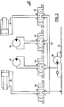
- a bending machine 10 is shown schematically in plan view, which comprises a horizontally lying processing table 12.
- two bending carriages 14 and 16 are slidably arranged in the longitudinal direction of the processing table 12, by means of which steel materials 18, preferably rod-shaped, to be introduced into the bending machine 10 are to be bent, as described in more detail below.
- These bars 18 enter the machine from a material store 20, wherein a plurality of bars 18 can be bent simultaneously by means of the bending slide 14 and 16.
- the material store 20 can be part of a processing line shown schematically in FIG. 3, which is arranged between the bending machine 10 and a bar cutting machine 22.
- the rod cutting machine can obey a principle as described in German patent application 32 06 673 by the same applicant.
- the bending machine 10 can be programmed via a keyboard 24 so as to cold-deform the materials 18 to the desired extent.
- the work surface 12 has a slot running vertically or almost vertically to accommodate several round materials to be arranged one above the other, which is laterally limited by the bending slides 14 and 16.
- a container 26 is also indicated, into which the bent materials 29 can be thrown by hand.
- an automatic ejection device is integrated in the machine 10.
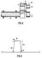
- Each bending slide 14 or 16 consists of a bending crank 28, a bending mandrel 30 and a drive 32, 34, 36 and 38.
- the bending crank 28 moves at a distance around the bending mandrel 30. Between the bending crank 28 and the bending mandrel 30 there are then materials to be deformed.
- the bending crank 28 comprises an eccentrically mounted roller mandrel 40, optionally rotatable about its axis, which is fixed immovably via two opposing threads 42 and 44 in the desired position (infinitely adjustable axis distance bending roller 40, bending mandrel 30), so that independently the bending mandrel 40 cannot be released from the direction of rotation of the bending crank 28.
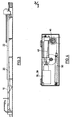
- the bending crank 28 is also received eccentrically by a shaft 46 which is connected to one of the hydraulic cylinders 36 or 38.
- the longitudinal movement of the hydraulic cylinder 36 or 38 is converted into the desired rotary movement via a chain 48.
- the chain 48 cooperating with the shaft 46 is connected at one end to the hydraulic cylinder 36 or 38 and at the other end via a spring-biased element 50. The exact structure and the mode of operation can easily be seen from FIG. 4.
- the translatory movement takes place Movement of the bending slide 14 or 16 itself preferably via hydraulic motors 32 and 34 with a rotary output movement.
- Both the hydraulic cylinders 36 and 38 and the hydraulic motors 32 and 34 are, as is clearly shown in FIG. 2, according to the invention in a hydraulic circuit 52.
- This has the advantage that all drive means can be operated with a single unit, so that complex monitoring and control devices are not required. But even if only a single hydraulic circuit is required, it is nevertheless ensured that all drive means 32 to 38 can be operated completely independently of one another.
- the individual drive means 32, 34, 36, 38 in the circuit 52 are now arranged as follows.
- the first hydraulic motor 32 is located behind the pump 56 conveying the operating medium 54.
- the second hydraulic motor 34 is arranged in a circuit-like manner behind the first hydraulic motor 32. Then the hydraulic cylinders 38 and 36 follow to close the circuit.
- the connection between the circuit 52 and the drive elements 32 to 38 is made via solenoid valves 58, 60, 62 and 64. If all valves 58 to 64 are closed, the operating means 54 runs freely in the circuit 52. Now z.
- valve 60 If the valve 60 is activated in such a way that a connection to the hydraulic motor 32 takes place — consequently a connection PB / AT or PA / BT is established — the valves 62, 64 and 58 can otherwise flow back directly without pressure when the valves 62, 64 are not activated. However, if the valve 62 is also actuated, ie if both bending slides 14 and 16 are to be displaced at the same time, the hydraulic motor 34 is acted upon by the return fluid of the motor 32 without the independence of the actuation being canceled thereby. Accordingly, the return fluid of the engine 34 can act on the hydraulic cylinders 38/36.
- An essential feature of the invention is that during the bending process at least one section of the material 18 having an angled end is held between the mandrel and the bending crank in such a way that there is immovability when the material is bent with the other bending slide.
- a corresponding bending process will now be explained in more detail with reference to FIG. 6.
- the rod-shaped material 66 shown schematically in FIG. 6 is first angled at the left end 68, ie the bending crank 72 is rotated clockwise around the bending mandrel 70. In the angled state, the bending crank 72 therefore assumes the position 74. In this position, the end 68 between the mandrel 70 and the bending crank 74 is fixed immovably.
- the bending mandrel 70 is then located on the inside at the intersection of the legs of the material 66 that describe an angle to one another, and the bending crank 74 is located on the outside of the angled end section 68.
- the right end 76 of the material 66 can then be bent to the desired extent.
- a bending crank 78 is in turn rotated around a bending mandrel 80.
- the bending crank 78 returns to its starting position and the bending slide comprising the mandrel 80 and the bending crank 78.
- 82 is shifted from position B to position C.
- a bending process can then be carried out again, so that the material 66, viewed from its center 84, has the desired geometric shape with regard to its right side.
- the material 66 is then held in its upper position (reference numeral 86) by the bending slide 82 between the bending mandrel 18 and the bending crank 78.
- the bending slide 88 comprising the bending mandrel 70 and the bending crank 72 is actuated in such a way that the bending crank 74 is turned back into its starting position, so that the bending slide 88 can subsequently be moved from the position A to the position D.
- the bending crank 72 is then rotated around the bending mandrel 70 (reference number 90), so that the material 66 then has the desired bending shape.
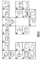
- FIG. 7 and 8 show other bending shapes by way of example, the bending process being carried out in the corresponding sequence in steps D ', E, F, G, H, I, K, L and M, N, 0, P, R, S is done.
- the respective material is immovably fixed during the bending processes E, F, G, H or N, 0, P by the bending slide in the position D 'or M, whereas in the bending processes I, K and L or R and S it is set in the H or P position.
- the shaped materials are removed from the bending slide so that they can be moved back into their basic position, that is to say D ', E or M, N.
- FIG. 9 A bending process is schematically shown once again in FIG. 9, which corresponds to that of FIGS. 6 to 8 in the course of the method.
- the dashed representation of the right leg 92 should make it clear that when a closed figure is formed, relaxation takes place such that the leg 92 is moved to the right by turning the bending crank 94 back, so that when the left leg 96 is bent in the direction of the leg 92- an undesired further deformation of this cannot take place.
- the leg 92 is relaxed to the extent and thus the bending crank 94 is turned back, as corresponds to the elastic deformation. This ensures that overbending cannot occur when the leg ends 98 or 100 collide, so that the cold-formed end product also exhibits the desired geometry.
- the relaxation is basically dependent on the strength of the to be bent materials, but experience has shown that a turning back of the bending crank 94 to 15 0 induces relaxation, which ensures that almost all common materials normal strength which is excluded to avoid over bending .
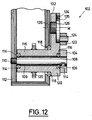
- FIG. 12 shows a particularly inventive design of a bending crank 102 that is rotatable about a bending mandrel 108.
- the bending mandrel 108 is the end of a fixed shaft 109, which in turn is arranged non-rotatably via a thread 110 in a section of the bending slide housing 112.
- Interchangeable bending templates 104 can be placed on the bending mandrel 108 and are held non-rotatably on the bending mandrel 108, for example, by means of a pan spring 106 or elements having the same effect.
- the bending crank 102 is now rotated about the shaft 109, the bending crank 102 being supported via a hollow cylinder section 116 via bearings 114 on the shaft 108 and via bearings 118 relative to the housing 112. Furthermore, the hollow cylinder section 116 has a drive pinion 120, via which the bending crank 102 is rotated in the manner described above.
- the bending bucket 102 now has a roller mandrel 122 eccentrically to the axis of rotation, which is firmly connected to an eccentric disk 126 via a pin 124.
- the roller mandrel 122 can be rotatably mounted about the pin 124.
- the mandrel 104 is arranged non-rotatably.
- the eccentric disk 126 is connected to a leg 132 protruding from the hollow cylinder 116 by means of an eccentric pin 136 , the thread of which is selected such that when the bending crank 102 is turned to bend the material 18 to be inserted between the roll mandrel 122 and the mandrel 108 or the bending template 104, it is tightened the eccentric disc 126 takes place without changing the position of the bending roller.
- spacing elements 134 protrude from the side of the eccentric disk facing the bending crank 102, by means of which the eccentric disk is fixed to the section 132 of the bending crank 102 facing away from it without play.
- the eccentric disk 126 is clamped when the pin 136 is non-positively locked by means of a roller mandrel 126 with the material 18 to be located between the latter and the bending template 128 (for example, the bending crank is rotated counterclockwise , the slope of the eccentric mandrel is right-hand).
- the bending crank 102 with the bending mandrel 122 is now rotated on a circle X 1 around the shaft 108 as the center point, the radius of the roller mandrel 120 depending on its position relative to the center point M being greater or smaller than X 1 .
- the radius X 2 is smaller than X 1
- the radius X 3 is larger than X 1 .
- the bending templates 128 and 130 can have different diameters.
- a counter bearing 136 is also shown in FIGS. 13 and 14 in order to hold the materials 18 in a horizontal position in the exemplary embodiment during bending with respect to the section not to be deformed.
Abstract
Description
Die Erfindung bezieht sich auf ein Verfahren sowie eine Vorrichtung zum Biegen von stabförmigen Materialien wie z.B. Bewehrungsstählen, umfassend zumindest einen Biegedorn und eine um diesen drehbar angeordnete Biegekurbel.The invention relates to a method and an apparatus for bending rod-shaped materials such as e.g. Reinforcing steels, comprising at least one bending mandrel and a bending crank arranged rotatably around it.
Um z. B. Stahleinlagen für Stahlbeton kalt zu verformen, finden Biegemaschinen Anwendung, die einen Biegetisch umfassen, auf denen Biegeteller oder -flügel z.B. hydraulisch angetrieben werden. Gebogen wird von dem auf dem Biegeteller im Abstand veränderbaren Exzenter oder Biegekurbel um" die auf die Achse aufsteckbare Biegerolle oder Biegedorn verschiedenen Durchmessers. Der oder die Stäbe legen sich dabei gegen eine feste Rolle und ein Widerlager. Ein Verformen von runden Materialien mit entsprechenden Maschinen ist nicht nur recht personalaufwendig, da das Einlegen und Verschieben der Materialien im wesentlichen von Hand erfolgt, sondern sie zeigen auch den Nachteil, daß die gebogenen Materialien hohe Toleranzen aufweisen, so daß ein hoher Ausschuß insbesondere dann auftritt, wenn geometrisch komplizierte Formen gebogen werden sollen.To z. B. Cold deforming steel inserts for reinforced concrete, bending machines are used which comprise a bending table, on which bending plates or wings e.g. are hydraulically driven. The eccentric or bending crank, which can be changed at a distance on the bending plate, bends around "the bending roller or mandrel of various diameters that can be plugged onto the axis. The rod or rods lie against a fixed roller and an abutment. A deformation of round materials with appropriate machines Not only does it require a lot of personnel, since the materials are essentially inserted and moved by hand, but they also have the disadvantage that the bent materials have high tolerances, so that a high level of waste occurs particularly when geometrically complicated shapes are to be bent.
Aufgabe der vorliegenden Erfindung ist es, ein Verfahren und eine Vorrichtung der eingangs beschriebenen Gattung derart auszubilden, daß ein weitgehend automatischer Biegeprozeß stattfindet, durch den Endprodukte zur Verfügung gestellt werden, die eine hohe Genauigkeit hinsichtlich der gewünschten Endform aufweisen. Dabei soll die Vorrichtung konstruktiv einfach aufgebaut und zu handhaben sein, so daß insbesondere auch ungeschultes Personal eine Bedienung vornehmen kann.The object of the present invention is to develop a method and a device of the type described in the introduction in such a way that a largely automatic bending process takes place, by means of which end products are made available which are highly accurate with regard to the desired final shape. The device should be of simple construction and easy to handle, so that even untrained personnel can operate it.
Die Aufgabe wird erfindungsgemäß dadurch gelöst, daß das stabförmige Material von zwei jeweils einen Biegedorn, eine Biegekurbel sowie einen Antrieb für diese umfassenden Biegeschlitten derart erfaßt und gebogen wird, daß zumindest nach dem Umbiegen eines Materialendes bei den weiteren Biegevorgängen ein Abschnitt des -Materials abwechselnd von einem der Biegeschlitten unverrückbar festgelegt wird, während der das Material nicht festhaltende Biegeschlitten jenes biegt oder entlang dessen verschoben wird. Erfindungsgemäß wird demzufolge vorgeschlagen, daß die von der Biegemaschine kalt zu verformenden Stahlmaterialien während des Biegens in der Maschine nicht verrückt werden können, so daß sichergestellt ist, daß die Materialien die gewünschte Geometrie bei geringer Toleranz erhalten. Dadurch, daß die Biegeschlitten sowohl die Aufgabe zu erfüllen haben, die zu verformenden Materialien festzuhalten bzw. im gewünschten Umfang zu verformen, ergibt sich erkennbar eine einfache Konstruktion, die nicht nur eine Wartungsfreundlichkeit zeigt, sondern sicherstellt, daß eine geringe Störanfälligkeit gegeben ist. Dabei kann selbstverständlich das Verfahren der Schlitten bzw. das Halten der Materialien durch die Schlitten programmgesteuert werden, ohne daß es hierzu weiterer Erläuterungen bedarf. Demzufolge kann der Biegevorgang automatisch ablaufen, nachdem man die Maschine so programmiert hat, daß die Biegeschlitten in der gewünschten Taktfolge die erforderlichen Positionen einnehmen, um wahlweise das Material unverrückbar festzuhalten oder dieses zu verbiegen. Um unabhängig von der Materialstärke sicherzustellen, daß die von einem Biegeschlitten erfaßten Materialien während dies Biegevorganges durch einen anderen Biegeschlitten nicht verrückt werden können, werden die Biegeschlitten jeweils im Bereich zweier einen Winkel zueinander beschreibenden Schenkel des Materials festgelegt, wobei der feststehende Biegedorn im Schnittpunkt der Schenkel innen anliegt und die Biegekurbel außen an dem Schenkel positioniert wird, der von der im unverformten Zustand des Materials vorgebenen Längsachse abgewinkelt ist. Die Biegeschlitten selbst werden nach einer weiteren Ausgestaltung der Erfindung in einem einzigen Hydraulikkreislauf angeordnet, wobei sowohl die Verschiebebewegung der Biegeschlitten als auch die Drehbewegung der Biegekurbeln um die Biegedorne herum völlig unabhänig voneinander erfolgen kann. Daraus resultiert der Vorteil, daß im wesentlichen mit einem einzigen Antriebsaggregat, also der die Betriebsflüssigkeit fördernden Pumpe, die einzelnen Antriebselemente beaufschlagt werden können, wobei die translatorische Bewegung der Biegeschlitten vorzugsweise über Hydromotoren erfolgt, deren Ausgangsbewegung rotatorisch ist, wohingegen die Drehbewegung der Biegekurbeln über Hydrozylinder erfolgt, deren gradlinige Ausgangsbewegung mittels einer an einem Ende von einem Federelement erfaßten Kette in eine Drehbewegung umgesetzt wird.The object is achieved in that the rod-shaped material is grasped and bent by two bending mandrels, a bending crank and a drive for these comprehensive sliding carriages in such a way that at least after the bending of a material end in the further bending processes, a section of the material alternately from one of the bending carriages is fixed immovably, while the bending carriage that is not holding the material bends or is displaced along the latter. According to the invention it is therefore proposed that the steel materials to be cold-formed by the bending machine cannot be moved during the bending in the machine, so that it is ensured that the materials obtain the desired geometry with a low tolerance. The fact that the bending slides both have the task of holding the materials to be deformed or deforming them to the desired extent results in a simple construction which not only shows ease of maintenance but also ensures that there is little susceptibility to failure. The process of the carriage or the holding of the materials by the carriage can of course be program-controlled without the need for further explanations. As a result, the bending process can take place automatically after the machine has been programmed so that the bending slides assume the required positions in the desired cycle sequence, in order to either hold the material firmly or to bend it. In order to ensure, regardless of the material thickness, that the materials gripped by a bending slide cannot be moved by another bending slide during this bending process, the bending slides are each fixed in the region of two legs of the material which describe an angle to one another, the fixed mandrel at the intersection of the legs fits inside and the Bending crank is positioned on the outside of the leg, which is angled from the longitudinal axis specified in the undeformed state of the material. According to a further embodiment of the invention, the bending slides themselves are arranged in a single hydraulic circuit, both the sliding movement of the bending slides and the rotary movement of the bending cranks around the bending mandrels being able to take place completely independently of one another. This results in the advantage that the individual drive elements can be acted upon essentially by a single drive unit, i.e. the pump that supplies the operating fluid, the translational movement of the bending slides preferably being effected by hydraulic motors, the output movement of which is rotational, whereas the rotary movement of the bending cranks by hydraulic cylinders takes place, the linear output movement is converted into a rotary movement by means of a chain gripped at one end by a spring element.
Um auch sicherzugehen, daß z. B. bei der Verformung des Materials zu geschlossenen Figuren ein unerwünschtes weiteres Verbiegen aufeinander stoßender Schenkel nicht erfolgt, wird nach einer weiteren Ausgestaltung der Erfindung ein Spannungsabbau in dem von einem Biegeschlitten unverrückbar festgehaltenen Schenkel dadurch erzielt, daß eine Verdrehung der Biegekurbel derart erfolgt, daß ein "Öffnen" in einem Umfang erfolgt, der in etwa der elastischen Verformung des Materials entspricht. Dabei hat sich herausgestellt, daß ein Zurückdrehen der Biegekurbel um ca. 15° nahezu für sämtliche normalerweise zu verformenden Stahlmaterialien üblicher Stärken genügt.To make sure that z. B. in the deformation of the material to closed figures, an undesirable further bending of abutting legs does not occur, according to a further embodiment of the invention, a stress relief in the leg immovably held by a bending slide is achieved in that a rotation of the bending crank takes place such that a "Opening" takes place to an extent that corresponds approximately to the elastic deformation of the material. It has been found that turning the bending crank back by approx. 15 ° is almost sufficient for all steel materials of normal thickness that are normally to be deformed.
Eine Vorrichtung insbesondere bestimmt zur Durchführung des zuvor beschriebenen Verfahrens zeichnet sich dadurch aus, daß zwei entlang des zu verbiegenden Materials sowie entlang einer vorzugsweise horizontal angeordneten Arbeitsfläche verschiebbar angeordnete Biegedorne und Biegekurbeln sowie Antriebe umfassende Biegeschlitten vorgesehen sind, wobei die Biegeschlitten derart betätigbar sind, daß einer (erster) der Biegeschlitten dann das Material unverrückbar festhält, wenn ein anderer (zweiter) Biegeschlitten in eine Biegeposition bewegt wird und/oder das Material biegt.A device, in particular intended for carrying out the method described above, is characterized in that two bending mandrels and bending cranks and drives comprising drives which are displaceable along the material to be bent and along a preferably horizontally arranged working surface are provided, the bending slides being operable in such a way that one (first) the bending slide then the material immovable holds when another (second) bending slide is moved into a bending position and / or the material bends.
Die in einem Hydraulikkreislauf angeordneten Antriebselemente für die translatorische Bewegung der Biegeschlitten sowie die Drehbewegung der Biegekurbeln ist dabei erfindungsgemäß so vorgenommen, daß die von der Pumpe kommende Betriebsflüssigkeit erst die Antriebselemente für die Translationsbewegung nacheinander beaufschlagt, um anschließend die Antriebselemente für die Drehbewegung der Biegekurbeln gegebenenfalls zu durchströmen. Trotz des Anordnens in einem einzigen Hydraulikkreislauf ist sichergestellt, daß die Elemente völlig unabhängig voneinander aktiviert werden können. Durch das Verwenden eines einzigen Aggregats und Hydraulikkreislaufes wird u.a. der Vortel erzielt, daß aufwendige Überwachungsschaltungen nicht erforderlich werden. Außerdem ist aufgrund des hydraulischen Antriebs die Gewähr gegeben, daß die Antriebselemente überaus prompt auf Druckbeaufschlagung bzw. Druckabfall reagieren, so daß dadurch eine weitere Sicherheit gegeben ist, daß die Endformen der gebogenen stabförmigen Materialien die gewünschte Geometrie bei geringen Toleranzen aufweisen. Um eine optimale Funktionstüchtigkeit der Biegekurbeln sicherzustellen, umfassen diese einen exzentrisch gelagerten Rollendorn, der vorzugsweise über zwei gegenläufige Gewinde in gewünschter Position unverrückbar festgehalten wird, so daß unabhängig von der Krafteinwirkung auf diesen, also unabhängig, ob der Rollendorn eine Rechts- oder eine Linksdrehung vollführt, sichergestellt ist, daß ein unerwünschtes Verrücken nicht erfolgt. Der Rollendorn selbst ist dabei von einer von einer mit dem Hydraulikantrieb verbundenen Welle abragenden Zylinderscheibe oder Stab gehalten, wobei die Wellenachse mit der Achse des Biegedorns zusammenfällt. Auch besteht die Möglichkeit, den Rollendorn in Bezug auf die Biegedornachse , im unterschiedlichen Abstand dadurch anzuordnen, daß der Rollendorn auf einer Exzenterscheibe angeordnet wird, die über einen Zapfen mit der Biegekurbel verbunden ist. Dabei kann die Exzenterscheibe gedreht werden, um verschiedene Positionen in Bezug auf den Biegedorn einstellen zu können. Um jedoch zu verhindern, daß bei Krafteinwirkung auf die Biegerolle und damit die Exzenterscheibe diese gedreht wird, gehen von der Exzenterscheibe Abstandselemente wie Blockschrauben aus, die die Exzenterscheibe gegen eine zugeordnete Fläche der Biegekurbel abstützt. Ferner ist das Gewinde des Zapfens der Exzenterscheibe so gewählt, daß beim Biegevorgang ein Anziehen der Exzenterscheibe erfolgen soll, das jedoch durch die Abstandselemente ausgeglichen wird. Dadurch ist sichergestellt, daß eine eingestellte Position der Biegerolle stets beibehalten bleibt. Dieser Vorschlag ist im übrigen auch in anderen Biegeautomaten realisierbar und stellt insoweit einen eigenerfinderischen Vorschlag dar.The drive elements arranged in a hydraulic circuit for the translational movement of the bending slides and the rotary movement of the bending cranks are made according to the invention in such a way that the operating fluid coming from the pump only acts on the drive elements for the translational movement one after the other, in order to subsequently possibly drive the drive elements for the rotary movement of the bending cranks flow through. Despite being arranged in a single hydraulic circuit, it is ensured that the elements can be activated completely independently of one another. By using a single unit and hydraulic circuit, one of the advantages is that complex monitoring circuits are not required. In addition, due to the hydraulic drive, there is a guarantee that the drive elements react very promptly to pressurization or pressure drop, so that there is a further certainty that the end shapes of the bent rod-shaped materials have the desired geometry with small tolerances. In order to ensure optimal functionality of the bending cranks, they include an eccentrically mounted roll mandrel, which is preferably held immovably in the desired position via two counter-rotating threads, so that regardless of the force acting on it, i.e. regardless of whether the roll mandrel makes a right or a left turn , it is ensured that an undesirable displacement does not occur. The roll mandrel itself is held by a cylindrical disk or rod projecting from a shaft connected to the hydraulic drive, the shaft axis coinciding with the axis of the bending mandrel. There is also the possibility of arranging the roll mandrel at different distances from the bending mandrel axis in that the roll mandrel is arranged on an eccentric disk which is connected to the bending crank by means of a pin. The eccentric disc can be rotated to be able to set different positions in relation to the mandrel. However, to prevent that when force is exerted on the bending roller and thus on the eccentric disc, spacer elements such as block screws emanate from the eccentric disc, which supports the eccentric disc against an assigned surface of the bending crank. Furthermore, the thread of the pin of the eccentric disc is selected so that the eccentric disc should be tightened during the bending process, but this is compensated for by the spacer elements. This ensures that a set position of the bending roller is always maintained. This suggestion can also be implemented in other bending machines and is therefore a self-made suggestion.
Der Biegedorn selbst umfaßt vorzugsweise einen mit austauschbaren Aufsätzen (Biegeschablonen) zu versehenden feststehenden Mutterdorn, so daß sich dadurch der Vorteil ergibt, daß eine leichte Anpassung an unterschiedliche Dicken der Materialien gegeben ist.The bending mandrel itself preferably comprises a fixed mandrel to be provided with interchangeable attachments (bending templates), so that there is the advantage that there is a slight adaptation to different thicknesses of the materials.
Durch den erfindungsgemäßen Vorschlag, den Biegeablauf automatisch vorzunehmen, kann die erfindungsgemäße Vorrichtung in z. B. einer Bearbeitungsstraße eingesetzt werden, die eine das Material ablängende Schneidvorrichtung sowie einen zwischen dieser und jener vorgesehenen Puffer vorzugsweise in Form einer Rollbahn umfaßt. Erkennbar ergibt sich daraus ein weiterer nicht zu vernachlässigender Vorteil hinsichtlich der Durchsatzleistungen.Through the proposal according to the invention to make the bending process automatically, the device according to the invention can be used in e.g. B. a processing line can be used, which comprises a cutting device cutting the material and a buffer provided between this and that preferably in the form of a taxiway. This clearly results in another not negligible advantage in terms of throughput.
Weitere Einzelheiten, Vorteile und Merkmale ergeben sich aus den Ansprüchen der nachfolgenden Beschreibung und der Zeichnung, der - ohne daß es weiterer Erläuterungen bedarf - wesentliche Merkmale der erfindungsgemäßen Lehre zu entnehmen. sind, auch wenn diese nicht näher beschrieben werden.Further details, advantages and features emerge from the claims of the following description and the drawing, which - without further explanations being required - show essential features of the teaching according to the invention. are, even if they are not described in more detail.
Es zeigen:
- Fig. 1 eine erfindungsgemäße Vorrichtung in Draufsicht,
- Fig. 2 einen Hydraulikschaltplan,
- Fig. 3 einen Einsatz der Vorrichtung nach Fig. 1 in einer Arbeitsstraße,
- Fig. 4 eine Detaildarstellung eines Antriebs einer Biegekurbel,
- Fig. 5 einen Ausschnitt einer ersten Ausführungsform eines Biegeschlittens,
- Fig. 6 bis 9 schematische Darstellungen von Biegevorgängen,
- Fig. 10 und 11 Biegeformen von Rundstahl, die mit der erfindungsgemäßen Vorrichtung hergestellt werden können,
- Fig. 12 einen Ausschnitt einer zweiten Ausführungsform eines Biegeschlittens und
- Fig. 13 und 14 schematische Darstellungen von Biegevorgängen.
- 1 shows a device according to the invention in plan view,
- 2 shows a hydraulic circuit diagram,
- 3 shows an application of the device according to FIG. 1 in a work street,
- 4 shows a detailed illustration of a drive of a bending crank,
- 5 shows a detail of a first embodiment of a bending slide,
- 6 to 9 are schematic representations of bending processes,
- 10 and 11 bending shapes of round steel, which can be produced with the device according to the invention,
- Fig. 12 shows a detail of a second embodiment of a bending slide and
- 13 and 14 are schematic representations of bending processes.
In Fig. 1 ist schematisch eine Biegemaschine 10 in Draufsicht dargestellt, die einen horizontal liegenden Bearbeitungstisch 12 umfaßt. In Längsrichtung des Bearbeitungstisches 12 sind im Ausführungsbeispiel zwei Biegeschlitten 14 und 16 verschiebbar angeordnet, mittels derer in die Biegemaschine 10 einzubringende vorzugsweise stabförmig ausgebildete Stahlmaterialien 18 -wie nachstehend näher beschrieben- gebogen werden sollen. Diese Stäbe 18 gelangen von einem Materiallager 20 in die Maschine, wobei mehrere Stäbe 18 gleichzeitig mittels der Biegeschlitten 14 und 16 gebogen werden können. Das Materiallager 20 kann dabei ein Teil einer in Fig. 3 schematisch dargestellten Bearbeitungsstraße sein, das zwischen der Biegemaschine 10 und einer Stabschneidemaschine 22 angeordnet ist. Die Stabschneidemaschine kann dabei einem Prinzip gehorchen, wie es in der Deutschen Patentanmeldung 32 06 673 desselben Anmelders beschrieben ist. Das Materiallager 20, das eine Biegewagen-Rollbahn sein kann, dient dabei gleichzeitig als Puffer. Durch den Einsatz der Maschine 10 in einer Bearbeitungsstraße ergibt sich der Vorteil, daß ein hoher Durchsatz gegeben ist, ohne daß es hierzu näherer Erläuterungen bedarf. Die Biegemaschine 10 ist über eine Tastatur 24 programmierbar, um so die Materialien 18 im gewünschten Umfang kalt zu verformen. Ferner sei erwähnt, daß die Arbeitsfläche 12 einen vertikal oder nahezu vertikal zu ihr verlaufenden Schlitz zur Aufnahme von mehreren übereinander anzuordnenden Rundmaterialien aufweist, der von den Biegeschlitten 14 und 16 seitlich begrenzt wird. Neben der Maschine 10 ist ferner ein Container 26 angedeutet, in den die gebogenen Materialien 29 von Hand hineingeworfen werden können. Selbstverständlich besteht auch die Möglichkeit, daß eine automatische Auswurfvorrichtung in der Maschine 10 integriert ist.In Fig. 1, a
Jeder Biegeschlitten 14 bzw. 16 besteht aus einer Biegekurbel 28, einem Biegedorn 30 sowie einem Antrieb 32, 34, 36 bzw. 38. Dabei bewegt sich die Biegekurbel 28 im Abstand um den Biegedorn 30. Zwischen Biegekurbel 28 und Biegedorn 30 befinden sich dann die zu verformenden Materialien. Wie in Fig. 5 angedeutet, umfaßt die Biegekurbel 28 einen exzentrisch gelagerten gegebenenfalls um seine Achse drehbaren Rollendorn 40, der über zwei gegenläufige Gewinde 42 und 44 in gewünschter Position (stufenlos einstellbarer Achsenabstand Biegerolle 40, Biegedorn 30) unverrückbar festgelegt wird, so daß unabhängig von der Drehrichtung der Biegekurbel 28 ein Lösen des Biegedorns 40 nicht erfolgen kann. Die Biegekurbel 28 wird gleichfalls exzentrisch von einer Welle 46 aufgenommen, die mit einem der Hydrozylinder 36 oder 38 verbunden ist. Dabei wird die Längsbewegung des Hydrozylinders 36 oder 38 über eine Kette 48 in die gewünschte Drehbewegung umgesetzt. Die mit der Welle 46 zusammenwirkende Kette 48 ist dabei an einem Ende mit dem Hydrozylinder 36 bzw. 38 und mit dem anderen Ende über ein federvorgespanntes Element 50 verbunden. Der genaue Aufbau bzw. die Wirkungsweise ist leicht aus der Fig. 4 ersichtlich.Each bending
Wird die Drehbewegung der Biegekurbel 28 vorzugsweise mittels Hydrozylindern 36 und 38 hervorgerufen, so erfolgt die translatorische Bewegung der Biegeschlitten 14 bzw. 16 selbst vorzugsweise über Hydromotoren 32 und 34 mit rotatorischer Ausgangsbewegung. Sowohl die Hydrozylinder 36 und 38 als auch die Hydromotoren 32 und 34 befinden sich, wie Fig. 2 unmißverständlich zeigt, erfindungsgemäß in einem Hydraulikkreislauf 52. Dies hat den Vorteil, daß mit einem einzigen Aggregat sämtliche Antriebsmittel betrieben werden können, so daß aufwendige Überwachungs- und Steuerungseinrichtungen nicht erforderlich sind. Aber auch wenn nur ein einziger Hydraulikkreislauf erforderlich ist, so' ist dennoch sichergestellt, daß sämtliche Antriebsmittel 32 bis 38 völlig unabhängig voneinander betrieben werden können. Erfindungsgemäß sind die einzelnen Antriebsmittel 32, 34, 36, 38 in dem Kreislauf 52 nun wie folgt angeordnet. Hinter der das Betriebsmittel 54 fördernden Pumpe 56 befindet sich der erste Hydromotor 32. Hinter dem ersten Hydromotor 32 ist der zweite Hydromotor 34 kreislaufmäßig angeordnet. Sodann folgen die Hydrozylinder 38 bzw. 36, um den Kreislauf zu schließen. Im Ausführungsbeispiel nach Fig. 2 führt die Verbindung zwischen dem Kreislauf 52 und den Antriebselementen 32 bis 38, über Magnetventile 58, 60, 62 bzw. 64 hergestellt. Sind alle Ventile 58 bis 64 geschlossen, findet im Kreislauf 52 ein freier Durchlauf des Betriebsmittels 54 statt. Wird nun z. B. das Ventil 60 derart aktiviert, daß eine Verbindung zum Hydromotor 32 erfolgt -es wird demzufolge eine Verbindung PB/AT oder PA/BT hergestellt-, so kann bei ansonsten nicht aktivierten Ventilen 62, 64 und 58 das Betriebsmittel weiterhin unmittelbar drucklos zurückströmen. Wird jedoch auch das Ventil 62 betätigt, also wenn beide Biegeschlitten 14 und 16 gleichzeitig verschoben werden sollen, so- wird der Hydromotor 34 vom Rücklauffluid des Motors 32 beaufschlagt, ohne daß dadurch die Unabhängigkeit der Betätigung aufgehoben wird. Dementsprechend kann das Rücklauffluid des Motors 34 die Hydrozylinder 38/36 beaufschlagen. Gleiches kann selbstverständlich auch dann erfolgen, wenn nur einer der Hydromotoren 32 oder 34 oder keiner von diesen von dem Betriebsmittel 54 beaufschlagt wird. Aus der zuvor wiedergegebenen Schilderung ergibt sich, daß die Antriebsmittel 32 bis 38 für das - Betätigen der Biegeschlitten 14 und 16 in einem einzigen Hydraulikkreislauf 52 angeordnet sind und vollkommen unabhängig voneinander, aber auch gemeinsam aktiviert werden können.If the rotary movement of the bending crank 28 is preferably brought about by means of
Wesentliches Merkmal der Erfindung ist darin zu sehen, daß während des Biegevorganges zumindest ein ein abgewinkeltes Ende aufweisender Abschnitt des Materials 18 zwischen Biegedorn und Biegekurbel derart festgehalten wird, daß bei einem Biegen des Materials mit dem anderen Biegeschlitten eine Unverrückbarkeit gegeben ist. Anhand der Fig. 6 soll nun ein entsprechender Biegevorgang näher erläutert werden. Das in Fig. 6 schematisch dargestellte stabförmige Material 66 wird zunächst am linken Ende 68 abgewinkelt, d.h. daß um den Biegedorn 70 die Biegekurbel 72 im Uhrzeigersinn gedreht wird. Im abgewinkelten Zustand nimmt daher die Biegekurbel 72 die Position 74 ein. In dieser Stellung wird das Ende 68 zwischen Biegedorn 70 und Biegekurbel 74 unverrückbar festgelegt. Der Biegedorn 70 befindet sich dann innen im Schnittpunkt der einen Winkel zueinander beschreibenden Schenkel des Materials 66 und die Biegekurbel 74 befindet sich an der Außenseite des abgewinkelten Endabschnitts 68. Sodann kann im gewünschten Umfang ein Umbiegen des rechten Endes 76 des Materials 66 erfolgen. Zu diesem Zweck wird wiederum eine Biegekurbel 78 um einen Biegedorn 80 gedreht. Nachdem dieser Biegevorgang abgeschlossen ist, gelangt die Biegekurbel 78 in seine Ausgangsstellung zurück und der den Biegedorn 80 und die Biegekurbel 78 umfassende Biegeschlitten. 82 wird von der Position B in die Position C verschoben. Sodann kann erneut ein Biegevorgang vorgenommen werden, so daß das Material 66 hinsichtlich seiner rechten Seite betrachtet von seinem Mittelpunkt 84 aus die gewünschte geometrische Figur aufweist. Dieser Vorgang kann in beliebig vielen Strecken erfolgen. Sodann wird das Material 66 von dem Biegeschlitten 82 zwischen dem Biegedorn 18 und der Biegekurbel 78 in seiner oberen Stellung (Bezugszeichen 86) festgehalten. Daraufhin wird der den Biegedorn 70 und die Biegekurbel 72 umfassende Biegeschlitten 88 derart betätigt, daß die Biegekurbel 74 in seine Ausgangsstellung zurückgedreht wird, so daß anschließend ein Verfahren des Biegeschlittens 88 von der Position A in die Position D erfolgen kann. In dieser Stellung wird sodann die Biegekurbel 72 um den Biegedorn 70 gedreht (Bezugszeichen 90), so daß anschließend das Material 66 die gewünschte Biegeform aufweist. Sodann werden die Biegekurbeln aus der Position 86 und 90 in die Grundposition zurückgedreht, damit das Material aus den Schlitten 82 und 88 entfernt werden kann. Anschließend werden die Schlitten in die Position A und B zurückgefahren, damit mit neuem Material der gleiche Biegeablauf durchgeführt werden kann.An essential feature of the invention is that during the bending process at least one section of the material 18 having an angled end is held between the mandrel and the bending crank in such a way that there is immovability when the material is bent with the other bending slide. A corresponding bending process will now be explained in more detail with reference to FIG. 6. The rod-shaped
In den Fig. 7 und 8 sind beispielhaft andere Biegeformen aufgezeigt, wobei der Biegeprozeß in entsprechender Reihenfolge in den Schritten D', E, F, G, H, I, K, L bzw. M, N, 0, P, R, S erfolgt. Dabei wird das jeweilige Material während der Biegevorgänge E, F, G, H bzw. N, 0, P von dem Biegeschlitten in der Position D' bzw. M unverrückbar festgelegt, wohingegen bei den Biegevorgängen I, K und L bzw. R und S ein Festlegen in der Position H bzw. P erfolgt. Nachdem die Biegevorgänge abgeschlossen sind, werden, wie im Zusammenhang mit Fig. 6 erläutert, die geformten Materialien aus den Biegeschlitten entfernt, damit diese in ihre Grundposition, also D', E bzw. M, N zurückgefahren werden können.7 and 8 show other bending shapes by way of example, the bending process being carried out in the corresponding sequence in steps D ', E, F, G, H, I, K, L and M, N, 0, P, R, S is done. The respective material is immovably fixed during the bending processes E, F, G, H or N, 0, P by the bending slide in the position D 'or M, whereas in the bending processes I, K and L or R and S it is set in the H or P position. After the bending processes have been completed, as explained in connection with FIG. 6, the shaped materials are removed from the bending slide so that they can be moved back into their basic position, that is to say D ', E or M, N.
In Fig. 9 ist noch einmal ein Biegevorgang schematisch dargestellt, der im Verfahrensablauf denen der Fig. 6 bis 8 entspricht. Allerdings soll durch die gestrichelte Darstellung des rechten Schenkels 92 verdeutlicht werden, daß bei der Ausbildung einer geschlossenen Figur ein Entspannen dahingehend erfolgt, daß der Schenkel 92 nach rechts durch Rückdrehen der Biegekurbel 94 bewegt wird, damit beim Verbiegen -des linken Schenkels 96 in Richtung auf den Schenkel 92- ein unerwünschtes weiteres Verformen von diesem nicht erfolgen kann. Dabei wird in dem Umfang ein Entspannen des Schenkels 92 und somit ein Zurückdrehen der Biegekurbel 94 vorgenommen, wie es der elastischen Verformung entspricht. Dadurch ist sichergestellt, daß ein Überbiegen beim Aufeinanderstoßen der Schenkelenden 98 bzw. 100 nicht erfolgen kann, so daß das kaltverformte Endprodukt auch die gewünschte Geometrie zeigt. Zwar ist die Entspannung grundsätzlich von der Festigkeit der zu verbiegenden Materialien abhängig, jedoch hat die Erfahrung gezeigt, daß ein Zurückdrehen der Biegekurbel 94 um 150 eine Entspannung hervorruft, die sicherstellt, daß nahezu bei allen üblichen Materialien normaler Stärke die zu vermeidende Überbiegung ausgeschlossen wird.A bending process is schematically shown once again in FIG. 9, which corresponds to that of FIGS. 6 to 8 in the course of the method. However, the dashed representation of the
In den Fig. 10 und 11 sind beispielhaft verschiedene Biegeformen von Rundstahl aufgezeigt, die unter Anwendung der erfindungsgemäßen Lehre erzielt werden können. Man erkennt eine große Vielfalt, wobei darauf hinzuweisen ist, daß die Genauigkeit der Endprodukte sehr groß ist, so daß der Auswurf der nicht zu verwendenden kaltverformten Materialien überaus gering ist.10 and 11 show various bending shapes of round steel, which can be achieved using the teaching according to the invention. A great variety can be seen, although it should be noted that the accuracy of the end products is very high, so that the ejection of the cold-formed materials which are not to be used is extremely low.
In Fig. 12 ist eine besonders hervorzuhebende eigenerfinderische Ausgestaltung einer Biegekurbel 102 dargestellt, die um einen Biegedorn 108 drehbar ist. Der Biegedorn 108 ist im Ausführungsbeispiel das Ende einer feststehenden Welle 109, die ihrerseits unverdrehbar über ein Gewinde 110 in einem Abschnitt des Biegeschlittengehäuses 112 angeordnet ist. Auf den Biegedorn 108 sind austauschbare Biegeschablonen 104 aufsetzbar, die zum Beispiel über eine Panfeder 106 oder gleich wirkende Elemente unverdrehbar auf dem Biegedorn 108 festgehalten werden.FIG. 12 shows a particularly inventive design of a bending crank 102 that is rotatable about a bending
Um die Welle 109 wird nun die Biegekurbel 102 gedreht, wobei die Biegekurbel 102 über einen Hohlzylinderabschnitt 116 über Lager 114 auf der Welle 108 und über Lager 118 gegenüber dem Gehäuse 112- abgestützt ist. Ferner weist der Hohlzylinderabschnitt 116 ein Antriebsritzel 120 auf, über den die Drehung der Biegekurbel 102 in der zuvor beschriebenen Art erfolgt. Die Biegekürbel 102 weist nun exzentrisch zur Drehachse einen Rollendorn 122 auf, der über einen Zapfen 124 mit einer Exzenterscheibe 126 fest verbunden ist. Dabei kann der Rollendorn 122 um den Zapfen 124 drehbar gelagert sein. Im Gegensatz dazu ist der Biegedorn 104 unverdrehbar angeordnet. Gleiches gilt für auf die -wie erwähnt- auf dem Biegedorn 108 anzuordnenden Aufsätze bzw. Biegeschablonen 104 und 128, 130 gemäß Fig. 13 und Fig. 14. Die Exzenterscheibe 126 ist mit einem von dem Hohlzylinder 116 abragenden Schenkel 132 mittels eines Exzenterzapfens 136 verbunden, dessen Gewinde so gewählt ist, daß beim Drehen der Biegekurbel 102 zum Biegen der zwischen Rollendorn 122 und Biegedorn 108 bzw. Biegeschablone 104 einzulegendem Material 18 ein Festziehen der Exzenterscheibe 126 erfolgt, ohne daß die Position der Biegerolle verändert wird. Zu diesem Zweck ragen von der der Biegekurbel 102 zugewandten Seite der Exzenterscheibe Abstandselemente 134 ab, durch die die Exzenterscheibe spielfrei dem abgewandten Abschnitt 132 der Biegekurbel 102 festgelegt wird.The bending
Die Position der Exzenterscheibe 126 und damit des Rollendorns 122 in Bezug auf die Drehachse kann nun mittels der als Abstandselemente ausgebildeten Blockschrauben 134 eingestellt werden, um nachstehend aufgezeigte Aufgaben lösen zu können. Es ist nämlich gefordert, daß beim Biegen von Betonstahlmaterialien 18 vom Stabdurchmesser abhängige Biegeradien hergestellt werden. Nach den geltenden Bauvorschriften sind fünf verschiedene Verhältnisse einzuhalten. Es handelt sich dabei um: Biegedurchmesser = 4d oder 5d oder 7d oder 15d oder 20d mit d = Stabdurchmesser. Dies erfordert in einem Bereich von d-Durchmessern zwischen 24 und 560 mm sechzig verschiedene Biegeschablonen und die dazu erforderlichen Biegezapfeneinstellungen, sofern man die bekannten Biegevorrichtungen benutzt. Bei den bekannten Vorrichtungen muß nämlich bei Änderung der Biegeschablone entweder die Biegekurbel mit feststehendem Biegedorn jeweils ausgewechselt werden oder auf der Biegekurbel muß der Biegezapf.en umgesteckt werden. Das erfordert auch verschiedene Durchmesser der Rollendorne, da die Umsteckmöglichkeiten des Biegezapfens nicht in beliebig kleinen Schritten erfolgen kann, wohingegen sich die Durchmesser der zu biegenden Stähle im Millimeterbereich ändern. (Entsprechende bekannte Biegemaschinen sind zum Beispiel unter der Bezeichnung MUBEA BO 55, 32, 40L bekannt.)The position of the
Erfindungsgemäß wird nun nach den Vorschlägen der Fig. 12 und 5 dahingehend eine Vereinfachung erzielt, daß nur noch die Biegeschablonen 104, 128, 130 ausgewechselt werden müssen, wohingegen der Rollendorn 122 nach Lockern der Blockschrauben 134 um den Mittelpunkt M der Exzenterscheibe 126 in die erforderliche Biegestellung, die maximal um 2'E mit E maximaler Abstand vom Mittelpunkt M differieren kann (siehe Fig. 13). Ist die erforderliche Position des Rollendors 124 eingestellt, so werden die Blockschrauben angezogen, also die Exzenterscheibe 126 gegen die fläche 135 abgestützt. Da die Gewindesteigung des Exzentergewindezapfens 136 gegen die Drehrichtung der Biegekurbel 102 verläuft, ist bei Kraftschluß des Zapfens 136 mittels Rollendorn 126 mit dem zwischen diesem und Biegeschablone 128 zu liegendem Material 18 ein Klemmen der Exzenterscheibe 126 sichergestellt (Wird die Biegekurbel zum Beispiel entgegen dem Uhrzeigersinn gedreht, so ist die Steigung des Exzenterdornes rechtsgängig).According to the invention, a simplification is now achieved according to the proposals of FIGS. 12 and 5 in that only the bending
Die Biegekurbel 102 mit dem Biegedorn 122 wird nun auf einem Kreis X1 um die Welle 108 als Mittelpunkt gedreht, wobei der Radius des Rollendorns 120 in Abhängigkeit von seiner Stellung zum Mittelpunkt M größer oder kleiner als X1 sein kann. Im Ausführungsbeispiel nach Fig. 13 ist der Radius X2 kleiner als X1, wohingegen im Ausführungsbeispiel nach Fig. 14 der Radius X3 größer als X1 ist.The bending crank 102 with the bending
Auch erkennt man aus den Ausführungsbeispielen der Fig. 13 und 14, daß in Abhängigkeit von dem zu biegenden Material 18 bzw. zu erzielenden Biegeradius die Biegeschablonen 128 bzw. 130 unterschiedliche Durchmesser aufweisen können. Schließlich ist in den Fig. 13 und 14 noch ein Gegenlager 136 dargestellt, um die Materialien 18 beim Biegen hinsichtlich des nicht zu verformenden Abschnitts in einer im Ausführungsbeispiel horizontalen Lage zu halten.It can also be seen from the exemplary embodiments in FIGS. 13 and 14 that, depending on the
Claims (15)
dadurch gekennzeichnet,
daß das stabförmige Material (18, 66) von zwei jeweils einen Biegedorn (30, 70, 80, 104, 108, 128, 130), eine Biegekurbel (28, 72, 78, 102) sowie Antriebe (32, 34, 36, 38) umfassenden Biegeschlitten (14, 16, 82, 88) derart erfaßt und gebogen wird, daß nach dem Umbiegen eines Materialendes (68) bei den weiteren Biegevorgängen ein Abschnitt des Materials abwechselnd von einem der Biegeschlitten unverrückbar festgelegt wird, während der das Material nicht festhaltenden Biegeschlitten das Material biegt oder entlang dessen verschoben wird.1. A method for bending rod-shaped materials, such as reinforcing steels, comprising at least one bending mandrel and a bending crank arranged rotatably around it,
characterized,
that the rod-shaped material (18, 66) of two each have a bending mandrel (30, 70, 80, 104, 108, 128, 130), a bending crank (28, 72, 78, 102) and drives (32, 34, 36, 38) comprising the bending slide (14, 16, 82, 88) is gripped and bent in such a way that after the bending of a material end (68) during the further bending processes, a section of the material is alternately immovably fixed by one of the bending slides, during which the material does not holding the bending slide, the material bends or is moved along it.
dadurch gekennzeichnet,
daß der Biegeschlitten (14, 16, 82, 88) das Material im Bereich zweier einen Winkel zueinander beschreibenden Schenkel (68, 66; 76, 66) unverrückbar festlegt.2. The method according to claim 1,
characterized,
that the bending slide (14, 16, 82, 88) immovably fixes the material in the region of two legs (68, 66; 76, 66) that describe an angle to one another.
dadurch gekennzeichnet,
daß die Antriebselemente (32, 34, 36, 38) für die Biegeschlitten (14, 16, 82, 88) in .einem einzigen Hydraulikkreislauf (52) angeordnet werden.3. The method according to claim 1,
characterized,
that the drive elements (32, 34, 36, 38) for the bending slide (14, 16, 82, 88) are arranged in a single hydraulic circuit (52).
dadurch gekennzeichnet,
daß insbesondere bei der Verformung des Materials zu einer geschlossenen Figur wie zum Beispiel einem Rechteck vor der Biegung des letzten Schenkels (96) die Biegekurbel (94) des das Material unverrückbar festlegenden Biegeschlittens derart gedreht wird, daß ein Spannungsabbau des festgelegten Schenkels (92) des Materials in einem Umfang erfolgt, der der elastischen Verformung des Materials entspricht (Fig. 9).4. The method according to claim 1,
characterized,
that in particular when the material is deformed into a closed figure, such as a rectangle before the bending of the last leg (96), the bending crank (94) of the bending carriage which immovably fixes the material is rotated in such a way that a reduction in tension of the defined leg (92) of the Material takes place to an extent that corresponds to the elastic deformation of the material (Fig. 9).
dadurch gekennzeichnet,
daß zwei entlang des zu biegenden Materials (18, 66) verschiebbar angeordnete Biegedorne (30, 70, 80, 104, 108, 128, 130), Biegekurbeln (28, 72, 78, 94, 102) sowie Antriebe (32, 34, 36, 38) umfassende Biegeschlitten (14, 16, 82, 88) vorgesehen sind, wobei die Biegeschlitten derart betätigbar sind, daß einer der Biegeschlitten (14 bzw. 16; 88 bzw. 82) dann das Material (18, 66) unverrückbar festhält, wenn der anderer Biegeschlitten (16 bzw. 14; 82 bzw. 88) in eine Biegeposition bewegt wird und/oder das Material biegt. -5. Device for bending rod-shaped material, such as reinforcing steel, comprising at least one bending mandrel and a bending crank arranged rotatably around it, in particular for carrying out the method according to at least claim 1.
characterized,
that two bending mandrels (30, 70, 80, 104, 108, 128, 130), bending cranks (28, 72, 78, 94, 102) and drives (32, 34, 36, 38) comprising bending slides (14, 16, 82, 88) are provided, the bending slides being operable in such a way that one of the bending slides (14 or 16; 88 or 82) then immovably holds the material (18, 66) , if the other bending slide (16 or 14; 82 or 88) is moved into a bending position and / or the material bends. -
dadurch gekennzeichnet,
daß das Material (18, 66) in einem Abschnitt von einem Biegeschlitten (14, 16, 82, 88) unverrückbar festgelegt ist, in dem der Schnittpunkt von zwei Materialschenkeln liegt, wobei der Dorn (30, 70, 80, 104, 108, 128, 130) innen im Schnittpunkt der Schenkel und die Biegekurbel (28, 72, 74, 90; 78, 86; 94, 102, 122) außen an den von der mit der Bewegungsrichtung der Biegeschlitten zusammenfallenden Materiallängsachse abgewinkelten Schenkel (68, 76, 92) positioniert ist.6. The device according to claim 5,
characterized,
that the material (18, 66) is immovably fixed in a section by a bending slide (14, 16, 82, 88) in which the intersection of two material legs lies, the mandrel (30, 70, 80, 104, 108, 128, 130) on the inside at the intersection of the legs and the bending crank (28, 72, 74, 90; 78, 86; 94, 102, 122) on the outside on the legs (68, 76, 92) is positioned.
dadurch gekennzeichnet,
daß die Antriebselemente (32, 34, 36, 38) in einem einzigen Hydraulikkreislauf (52) angeordnet und von diesem betätigbar sind.7. The device according to claim 5,
characterized,
that the drive elements (32, 34, 36, 38) are arranged in a single hydraulic circuit (52) and can be actuated by the latter.
dadurch gekennzeichnet,
daß die Antriebsmittel (32, 34, 36, 38) sämtlichst unabhängig voneinander gleichzeitig oder getrennt betätigbar sind.8. The device according to claim 7,
characterized,
that the drive means (32, 34, 36, 38) can all be operated independently or simultaneously or separately.
dadurch gekennzeichnet,
daß die Antriebselemente (32, 36; 34, 38) der Biegeschlitten (14, 16, 82, 88) derart in dem Hydraulikkreislauf (52) angeordnet sind, daß die von der Pumpe (56) kommende Betriebsflüssigkeit (54) erst die Antriebselemente (32, 34) für die Translationsbewegung nacheinander beaufschlagt.9. The device according to claim 5,
characterized,
that the drive elements (32, 36; 34, 38) of the bending slides (14, 16, 82, 88) are arranged in the hydraulic circuit (52) in such a way that the operating fluid (54) coming from the pump (56) only the drive elements ( 32, 34) for the translational movement.
dadurch gekennzeichnet,
daß die Biegekurbel (28, 102) eine exzentrisch gelagerte Biegelrolle (40, 122) umfaßt, der unverrückbar positionierbar ist.10. The device in particular according to claim 5,
characterized,
that the bending crank (28, 102) comprises an eccentrically mounted bending roller (40, 122) which can be immovably positioned.
dadurch gekennzeichnet,
daß der Abstand zwischen der Achse der Biegerolle (40, 122) und der Drehachse (46, 108) der Biegekurbel (28, 102) veränderbar ist.11. The device according to claim 10,
characterized,
that the distance between the axis of the bending roller (40, 122) and the axis of rotation (46, 108) of the bending crank (28, 102) is variable.
dadurch gekennzeichnet,
daß die Biegelrolle (122, 124) von einer Exzenterscheibe (126) ausgeht, die um einen Zapfen (136) drehbar in der Biegekurbel (102, 132) angeordnet ist und über Abstandselemente (134) gegen eine Fläche (135) der Biegekurbel abstützbar ist, wobei der Zapfen eine Gewindesteigung aufweist, die der Drehrichtung der Biegekurbel entgegengesetzt ist.12. The device in particular according to claim 10 and / or claim 11,
characterized,
that the bending roller (122, 124) starts from an eccentric disc (126) which is rotatably arranged about a pin (136) in the bending crank (102, 132) and can be supported by means of spacer elements (134) against a surface (135) of the bending crank , wherein the pin has a thread pitch which is opposite to the direction of rotation of the bending crank.
dadurch gekennzeichnet,
daß der Biegedorn (30, 70, 80, 108) einen mit austauschbaren Aufsätzen (104, 128, 130) versehenen Mutterdorn umfaßt.13. The apparatus of claim 5 and / or claim 10,
characterized,
that the bending mandrel (30, 70, 80, 108) comprises a mother mandrel provided with interchangeable attachments (104, 128, 130).
dadurch gekennzeichnet,
daß die Arbeitsfläche (12) der Vorrichtung (10) horizontal oder nahez horizontal angeordnet ist und einen vertikal oder nahezu vertikal dazu verlaufenden von den Biegeschlitten (14, 16, 82, 88) seitlich begrenzten Schlitz zur Aufnahme mehrer übereinander angeordneter stabförmiger Materialien (18, 66) aufweist.14. The apparatus according to claim 5,
characterized,
that the working surface (12) of the device (10) is arranged horizontally or almost horizontally and a slot running vertically or almost vertically thereto and laterally delimited by the bending slides (14, 16, 82, 88) for receiving a plurality of rod-shaped materials (18, 66).
Priority Applications (1)
| Application Number | Priority Date | Filing Date | Title |
|---|---|---|---|
| AT84103662T ATE30861T1 (en) | 1983-04-06 | 1984-04-04 | METHOD AND DEVICE FOR BENDING ROD-SHAPED MATERIALS. |
Applications Claiming Priority (2)
| Application Number | Priority Date | Filing Date | Title |
|---|---|---|---|
| DE3312397 | 1983-04-06 | ||
| DE19833312397 DE3312397A1 (en) | 1983-04-06 | 1983-04-06 | METHOD AND DEVICE FOR BENDING ROD-SHAPED MATERIALS |
Publications (4)
| Publication Number | Publication Date |
|---|---|
| EP0121896A2 true EP0121896A2 (en) | 1984-10-17 |
| EP0121896A3 EP0121896A3 (en) | 1985-01-23 |
| EP0121896B1 EP0121896B1 (en) | 1987-11-19 |
| EP0121896B2 EP0121896B2 (en) | 1991-12-18 |
Family
ID=6195607
Family Applications (1)
| Application Number | Title | Priority Date | Filing Date |
|---|---|---|---|
| EP84103662A Expired - Lifetime EP0121896B2 (en) | 1983-04-06 | 1984-04-04 | Method of and device for bending bar-shaped materials |
Country Status (4)
| Country | Link |
|---|---|
| US (1) | US4702097A (en) |
| EP (1) | EP0121896B2 (en) |
| AT (1) | ATE30861T1 (en) |
| DE (2) | DE3312397A1 (en) |
Cited By (4)
| Publication number | Priority date | Publication date | Assignee | Title |
|---|---|---|---|---|
| WO1985005053A1 (en) * | 1984-04-30 | 1985-11-21 | Howard Bruce | Apparatus for fabricating concrete reinforcing stirrups and the welding thereof with rods to form a concrete reinforcing cage |
| EP0238026A1 (en) | 1986-03-14 | 1987-09-23 | Ruhl, Heinz | Method of and device for bending bar-shaped materials |
| EP0334353A1 (en) * | 1988-03-25 | 1989-09-27 | EVG Entwicklungs- u. Verwertungs- Gesellschaft m.b.H. | Method and machine for bending by preference bar material |
| DE3919607A1 (en) * | 1989-06-15 | 1991-01-03 | Heinz Ruhl | METHOD AND DEVICE FOR BENDING ROD-SHAPED MATERIAL |
Families Citing this family (10)
| Publication number | Priority date | Publication date | Assignee | Title |
|---|---|---|---|---|
| FR2657546B1 (en) * | 1990-01-26 | 1992-05-22 | Eaton Leonard Picot Sa | TWO-HEAD BENDING TUBE BENDING MACHINE. |
| CA2100530A1 (en) * | 1992-09-02 | 1994-03-03 | Michael W. Bogart | Needle curving apparatus |
| CA2106791A1 (en) * | 1992-10-09 | 1994-04-10 | Michael W. Bogart | Needle curving apparatus |
| US5388441A (en) * | 1992-12-29 | 1995-02-14 | United States Surgical Corporation | Needle curver with automatic feed |
| AT401360B (en) * | 1993-05-07 | 1996-08-26 | Progress Ag | BENDING SYSTEM FOR BARS |
| JP3685526B2 (en) * | 1995-07-14 | 2005-08-17 | 臼井国際産業株式会社 | Pipe bending machine |
| US5927132A (en) * | 1998-04-30 | 1999-07-27 | Schnell Spa | Method of bending bars |
| FR2900078B1 (en) * | 2006-04-24 | 2008-06-13 | Numalliance Soc Par Actions Si | WIRE BENDING MACHINE COMBINING A SEQUENTIAL STITCHING DEVICE AND A DEVICE USING A TOOLING PLATE |
| JP4626623B2 (en) * | 2007-03-12 | 2011-02-09 | トヨタ自動車株式会社 | Edgewise bending method and processing apparatus for flat rectangular material |
| CN112720033B (en) * | 2020-12-29 | 2022-04-12 | 新昌县三特自动化科技有限公司 | Full-automatic turning production line of miniature bearing |
Citations (1)
| Publication number | Priority date | Publication date | Assignee | Title |
|---|---|---|---|---|
| DE3206673A1 (en) | 1982-02-25 | 1983-09-01 | Helmut 6230 Kriftel Zahlaus | Device for cutting bar-shaped materials to size |
Family Cites Families (11)
| Publication number | Priority date | Publication date | Assignee | Title |
|---|---|---|---|---|
| US1546147A (en) * | 1924-04-25 | 1925-07-14 | Frederick A C Skinner | Pipe-bending machine |
| US1769570A (en) * | 1927-12-28 | 1930-07-01 | Hudson Motor Car Co | Apparatus for shaping sheet metal |
| DE1552970B2 (en) * | 1965-04-24 | 1977-01-13 | MACHINE FOR BENDING STENCILS, REINFORCEMENT IRON OR DGL. | |
| US3481177A (en) * | 1967-09-29 | 1969-12-02 | Lear Siegler Inc | Wire bending assembly |
| US3568300A (en) * | 1968-07-02 | 1971-03-09 | Zidell Explorations Inc | Method and apparatus for forming ship hulls |
| DE1752716A1 (en) * | 1968-07-05 | 1971-07-15 | Ernst Stegmann | Process for machine bending of wire and strip material and machine for carrying out the process |
| US3803893A (en) * | 1971-08-17 | 1974-04-16 | P Peddinghaus | Process for multiple bending of rods and a bending machine for carrying out this process |
| US3805576A (en) * | 1972-08-18 | 1974-04-23 | Cyril Bath Co | High speed multi-bending machine |
| GB1463522A (en) * | 1974-09-11 | 1977-02-02 | Russel Bowen Systems Ltd | Bending machines |
| AT338071B (en) * | 1974-12-16 | 1977-07-25 | Evg Entwicklung Verwert Ges | BENDING MACHINE FOR ROD-SHAPED MATERIAL, IN PARTICULAR FOR CONCRETE REINFORCEMENT ROD |
| IT1137724B (en) * | 1981-07-10 | 1986-09-10 | Mec Montorfano Di Montorfano V | BENDING UNIT FOR METAL PIPES AND WIRES AND START-UP PROCEDURE OF THE UNIT |
-
1983
- 1983-04-06 DE DE19833312397 patent/DE3312397A1/en not_active Withdrawn
-
1984
- 1984-04-04 AT AT84103662T patent/ATE30861T1/en not_active IP Right Cessation
- 1984-04-04 DE DE8484103662T patent/DE3467519D1/en not_active Expired
- 1984-04-04 EP EP84103662A patent/EP0121896B2/en not_active Expired - Lifetime
-
1986
- 1986-03-14 US US06/839,688 patent/US4702097A/en not_active Expired - Fee Related
Patent Citations (1)
| Publication number | Priority date | Publication date | Assignee | Title |
|---|---|---|---|---|
| DE3206673A1 (en) | 1982-02-25 | 1983-09-01 | Helmut 6230 Kriftel Zahlaus | Device for cutting bar-shaped materials to size |
Cited By (7)
| Publication number | Priority date | Publication date | Assignee | Title |
|---|---|---|---|---|
| WO1985005053A1 (en) * | 1984-04-30 | 1985-11-21 | Howard Bruce | Apparatus for fabricating concrete reinforcing stirrups and the welding thereof with rods to form a concrete reinforcing cage |
| EP0238026A1 (en) | 1986-03-14 | 1987-09-23 | Ruhl, Heinz | Method of and device for bending bar-shaped materials |
| EP0371960A2 (en) * | 1986-03-14 | 1990-06-06 | Ruhl, Heinz | Method for bending bar-shaped materials |
| EP0371960A3 (en) * | 1986-03-14 | 1990-06-20 | Ruhl, Heinz | Method of and device for bending bar-shaped materials |
| EP0334353A1 (en) * | 1988-03-25 | 1989-09-27 | EVG Entwicklungs- u. Verwertungs- Gesellschaft m.b.H. | Method and machine for bending by preference bar material |
| WO1989009104A1 (en) * | 1988-03-25 | 1989-10-05 | Evg Entwicklungs- Und Verwertungs-Gesellschaft M.B | Process and device for bending preferably rod-shaped material |
| DE3919607A1 (en) * | 1989-06-15 | 1991-01-03 | Heinz Ruhl | METHOD AND DEVICE FOR BENDING ROD-SHAPED MATERIAL |
Also Published As
| Publication number | Publication date |
|---|---|
| EP0121896B2 (en) | 1991-12-18 |
| DE3312397A1 (en) | 1984-10-11 |
| EP0121896B1 (en) | 1987-11-19 |
| DE3467519D1 (en) | 1987-12-23 |
| US4702097A (en) | 1987-10-27 |
| ATE30861T1 (en) | 1987-12-15 |
| EP0121896A3 (en) | 1985-01-23 |
Similar Documents
| Publication | Publication Date | Title |
|---|---|---|
| EP0121896B1 (en) | Method of and device for bending bar-shaped materials | |
| DE3739173A1 (en) | METHOD AND DEVICE FOR BENDING WORKPIECES | |
| CH648517A5 (en) | DEVICE FOR CUTTING A WIRE REEL AND BENDING THE WIRE END AROUND THE LAST COIL WINDING. | |
| DE2802621A1 (en) | METAL SHEET MOLDING MACHINE | |
| DE3016956A1 (en) | PLANNING MACHINE | |
| AT402032B (en) | MACHINE FOR THE PROCESSING OF GRID MATS FROM LENGTHED AND CROSSWIRE WELDED TOGETHER | |
| EP0622136A1 (en) | Device for the production of reinforcement meshes for concrete panels | |
| DE2164026A1 (en) | Bending device and method for producing bends | |
| DE2456303A1 (en) | METHODS AND DEVICES FOR EDGE FORMING ON A METAL PLATE | |
| DE4103134A1 (en) | DEVICE FOR PRODUCING CURVED SECTIONS ON A PIPE, IN PARTICULAR FOR PRODUCING A PIPE SNAKE | |
| DE1602064B2 (en) | ROLLING MILL FOR ROLLING OUT A METAL BLANK | |
| DE3816005A1 (en) | Machine for bending round bars and similar metal elements | |
| DE2940635C2 (en) | Section steel shears, punch or the like. | |
| DE1552148B2 (en) | BENDING DEVICE FOR CONTINUOUS FORMING A STRAIGHT WIRE INTO A WAVE-SHAPED SPRING WITH SECTIONS IN DIFFERENT PLANES | |
| DE10065255B4 (en) | Multistage press | |
| EP0371960A2 (en) | Method for bending bar-shaped materials | |
| DE750393C (en) | Device for changing the web height of a profile bar provided with flanges | |
| DE2630224A1 (en) | Drawing frame assembly - uses preassembled groups of lower roller sections to be coupled together | |
| DE3423052C2 (en) | ||
| DE2223461A1 (en) | DEVICE FOR ALIGNING AND BENDING BAR MATERIAL | |
| DE251470C (en) | ||
| DE1552148C (en) | Bending device for continuously reshaping a straight wire into a wave-shaped spring with sections in different planes | |
| DE2432991C3 (en) | Device for bending a pre-bent string of struts for a lightweight beam | |
| DE1452867A1 (en) | Pressing and regulating device for sheet leveling machines | |
| DE2317540A1 (en) | DEVICE FOR STRETCH BENDING PROFILE BEAMS |
Legal Events
| Date | Code | Title | Description |
|---|---|---|---|
| PUAI | Public reference made under article 153(3) epc to a published international application that has entered the european phase |
Free format text: ORIGINAL CODE: 0009012 |
|
| AK | Designated contracting states |
Designated state(s): AT CH DE FR GB IT LI SE |
|
| PUAL | Search report despatched |
Free format text: ORIGINAL CODE: 0009013 |
|
| AK | Designated contracting states |
Designated state(s): AT CH DE FR GB IT LI SE |
|
| 17P | Request for examination filed |
Effective date: 19841228 |
|
| 17Q | First examination report despatched |
Effective date: 19860313 |
|
| R17C | First examination report despatched (corrected) |
Effective date: 19860904 |
|
| GRAA | (expected) grant |
Free format text: ORIGINAL CODE: 0009210 |
|
| AK | Designated contracting states |
Kind code of ref document: B1 Designated state(s): AT CH DE FR GB IT LI SE |
|
| REF | Corresponds to: |
Ref document number: 30861 Country of ref document: AT Date of ref document: 19871215 Kind code of ref document: T |
|
| REF | Corresponds to: |
Ref document number: 3467519 Country of ref document: DE Date of ref document: 19871223 |
|
| ITF | It: translation for a ep patent filed |
Owner name: STUDIO JAUMANN |
|
| GBT | Gb: translation of ep patent filed (gb section 77(6)(a)/1977) | ||
| ET | Fr: translation filed | ||
| PLBI | Opposition filed |
Free format text: ORIGINAL CODE: 0009260 |
|
| REG | Reference to a national code |
Ref country code: CH Ref legal event code: PUE Owner name: HEINZ RUHL |
|
| 26 | Opposition filed |
Opponent name: MUHR UND BENDER MASCHINENBAU GMBH Effective date: 19880507 |
|
| REG | Reference to a national code |
Ref country code: FR Ref legal event code: TP |
|
| ITPR | It: changes in ownership of a european patent |
Owner name: CESSIONE;RUHL, HEINZ |
|
| RIN2 | Information on inventor provided after grant (corrected) |
Free format text: ZAHLAUS, HELMUT |
|
| RAP2 | Party data changed (patent owner data changed or rights of a patent transferred) |
Owner name: RUHL, HEINZ |
|
| ITTA | It: last paid annual fee | ||
| PUAH | Patent maintained in amended form |
Free format text: ORIGINAL CODE: 0009272 |
|
| STAA | Information on the status of an ep patent application or granted ep patent |
Free format text: STATUS: PATENT MAINTAINED AS AMENDED |
|
| 27A | Patent maintained in amended form |
Effective date: 19911218 |
|
| AK | Designated contracting states |
Kind code of ref document: B2 Designated state(s): AT CH DE FR GB IT LI SE |
|
| REG | Reference to a national code |
Ref country code: CH Ref legal event code: AEN |
|
| ITF | It: translation for a ep patent filed |
Owner name: STUDIO JAUMANN |
|
| PGFP | Annual fee paid to national office [announced via postgrant information from national office to epo] |
Ref country code: SE Payment date: 19920331 Year of fee payment: 9 Ref country code: CH Payment date: 19920331 Year of fee payment: 9 |
|
| PGFP | Annual fee paid to national office [announced via postgrant information from national office to epo] |
Ref country code: GB Payment date: 19920406 Year of fee payment: 9 |
|
| PGFP | Annual fee paid to national office [announced via postgrant information from national office to epo] |
Ref country code: AT Payment date: 19920410 Year of fee payment: 9 |
|
| ET3 | Fr: translation filed ** decision concerning opposition | ||
| GBTA | Gb: translation of amended ep patent filed (gb section 77(6)(b)/1977) | ||
| PGFP | Annual fee paid to national office [announced via postgrant information from national office to epo] |
Ref country code: DE Payment date: 19920424 Year of fee payment: 9 |
|
| PGFP | Annual fee paid to national office [announced via postgrant information from national office to epo] |
Ref country code: FR Payment date: 19920429 Year of fee payment: 9 |
|
| PG25 | Lapsed in a contracting state [announced via postgrant information from national office to epo] |
Ref country code: GB Effective date: 19930404 Ref country code: AT Effective date: 19930404 |
|
| PG25 | Lapsed in a contracting state [announced via postgrant information from national office to epo] |
Ref country code: SE Effective date: 19930405 |
|
| PG25 | Lapsed in a contracting state [announced via postgrant information from national office to epo] |
Ref country code: LI Effective date: 19930430 Ref country code: CH Effective date: 19930430 |
|
| GBPC | Gb: european patent ceased through non-payment of renewal fee |
Effective date: 19930404 |
|
| PG25 | Lapsed in a contracting state [announced via postgrant information from national office to epo] |
Ref country code: FR Effective date: 19931229 |
|
| REG | Reference to a national code |
Ref country code: CH Ref legal event code: PL |
|
| PG25 | Lapsed in a contracting state [announced via postgrant information from national office to epo] |
Ref country code: DE Effective date: 19940101 |
|
| REG | Reference to a national code |
Ref country code: FR Ref legal event code: ST |
|
| EUG | Se: european patent has lapsed |
Ref document number: 84103662.7 Effective date: 19931110 |