EP0121873A2 - Method and apparatus for bending spacekeeping profiles for thermopane glasses - Google Patents
Method and apparatus for bending spacekeeping profiles for thermopane glasses Download PDFInfo
- Publication number
- EP0121873A2 EP0121873A2 EP84103516A EP84103516A EP0121873A2 EP 0121873 A2 EP0121873 A2 EP 0121873A2 EP 84103516 A EP84103516 A EP 84103516A EP 84103516 A EP84103516 A EP 84103516A EP 0121873 A2 EP0121873 A2 EP 0121873A2
- Authority
- EP
- European Patent Office
- Prior art keywords
- profile
- bending
- bend
- outside
- pivot
- Prior art date
- Legal status (The legal status is an assumption and is not a legal conclusion. Google has not performed a legal analysis and makes no representation as to the accuracy of the status listed.)
- Granted
Links
Images

Classifications
-
- E—FIXED CONSTRUCTIONS
- E06—DOORS, WINDOWS, SHUTTERS, OR ROLLER BLINDS IN GENERAL; LADDERS
- E06B—FIXED OR MOVABLE CLOSURES FOR OPENINGS IN BUILDINGS, VEHICLES, FENCES OR LIKE ENCLOSURES IN GENERAL, e.g. DOORS, WINDOWS, BLINDS, GATES
- E06B3/00—Window sashes, door leaves, or like elements for closing wall or like openings; Layout of fixed or moving closures, e.g. windows in wall or like openings; Features of rigidly-mounted outer frames relating to the mounting of wing frames
- E06B3/66—Units comprising two or more parallel glass or like panes permanently secured together
- E06B3/673—Assembling the units
- E06B3/67304—Preparing rigid spacer members before assembly
- E06B3/67308—Making spacer frames, e.g. by bending or assembling straight sections
- E06B3/67313—Making spacer frames, e.g. by bending or assembling straight sections by bending
-
- B—PERFORMING OPERATIONS; TRANSPORTING
- B21—MECHANICAL METAL-WORKING WITHOUT ESSENTIALLY REMOVING MATERIAL; PUNCHING METAL
- B21D—WORKING OR PROCESSING OF SHEET METAL OR METAL TUBES, RODS OR PROFILES WITHOUT ESSENTIALLY REMOVING MATERIAL; PUNCHING METAL
- B21D53/00—Making other particular articles
- B21D53/74—Making other particular articles frames for openings, e.g. for windows, doors, handbags
-
- B—PERFORMING OPERATIONS; TRANSPORTING
- B21—MECHANICAL METAL-WORKING WITHOUT ESSENTIALLY REMOVING MATERIAL; PUNCHING METAL
- B21D—WORKING OR PROCESSING OF SHEET METAL OR METAL TUBES, RODS OR PROFILES WITHOUT ESSENTIALLY REMOVING MATERIAL; PUNCHING METAL
- B21D7/00—Bending rods, profiles, or tubes
- B21D7/02—Bending rods, profiles, or tubes over a stationary forming member; by use of a swinging forming member or abutment
Definitions
- the invention relates to a method for bending hollow, filled with desiccant spacer profiles for insulating glass panes, wherein the respective profile is detected in particular in front of and behind a pivot point and is bent about the pivot point - preferably by 90 °.
- the invention further relates to a device for bending a hollow spacer profile for insulating glass panes filled with desiccant, with a tensioning device lying approximately in the feed direction of the profile and a; Device for grasping the leg to be bent and an abutment for fixing the inside of the curvature.
- the desiccant located in the interior of the hollow profile can be partially displaced out of the region of curvature from the outside of the bend during the bending process and, at the same time, the profile outside - as already mentioned - can be elongated or stretched, preferably rolled out. It is also conceivable for the profile side walls to be at least partially elongated or rolled out, which at least close to the outside of the profile also undergo stretching during bending.
- An embodiment of the method according to the invention of particular importance can consist in the fact that the bending area of the profile is deformed several times during the bending process, in particular with high frequency, alternately in one and the other direction of the profile course, in particular cold rolled. Such a back and forth movement of the rolling process displaces the desiccant particularly well and results in the desired rolling out of the profile material, so that the bending process itself can be carried out in a relatively short time.
- a profile region of approximately 2 cm or less, preferably approximately one cm in length, of the profile is additionally deformed, preferably cold, in particular rolled at a high frequency. It is possible for at least 10 to 40, possibly about 30 hammering or rolling operations per second to be carried out on the bending area during the bending process. This is possible above all through the advantageous back and forth movement of the rolling, which can take place at a correspondingly high frequency.
- the later apex area of the bie tion of the profile additionally processed, in particular rolled.
- the profile area is additionally deformed, which begins before the apex of the bend and extends approximately to the apex or just behind it.
- the additional molding process during the bend can force and roll some material into the particularly stressed apex region of the bend, so that the stretching of the material carried out there is well supported.
- the above-mentioned device for bending a hollow spacer profile for insulating glass panes filled with desiccant which has a tensioning device lying approximately in the feed direction of the profile and a device for detecting the leg to be bent, as well as an abutment for fixing the inside of the resulting curvature, can be the solution the task also mentioned above can be characterized by at least one tool acting on at least the outer region of the bend for mechanical plastic deformation, in particular elongation or extension of the outer region during the bending process.
- a pressure roller or the like lying with its axis of rotation parallel to the bending axis is provided as a tool for plastically deforming the outside of the profile during its bending, which, under contact pressure, relative to that of the bending mandrel or the like. Abutment facing away side of the profile can be moved back and forth and pushed forward or pressed transversely to this back and forth movement.
- a particularly expedient embodiment of the device according to the invention can consist in that the roller is arranged at the end of a pivoting lever which can be driven for the back-and-forth movement in the pivoting direction and that in addition an effective device in the direction of this lever is provided for pressing the roller.
- the use of swivel levers for the drive allows different ratios or reductions depending on the relation of the distances between the points of attack of the drive devices, the pressure roller and the swivel bearing, in order to be able to match corresponding forces, paths and / or speeds.
- a spike-shaped abutment can be provided, around which the profile can be bent, and this abutment can simultaneously form the inner end of a flap or the like which can be pivoted about its center and which lies against the inside of the leg to be bent during the bending process and together with it an outer bending tool or the like. Aligned and kept straight. This prevents the leg to be bent from experiencing uncontrolled curvatures at a distance from the abutment.
- a stop or the like which overlaps the profile to be bent can be provided on the top of the mandrel. During the bending process, the side surface is above all against buckling or buckling secured at the top.
- an impact tool preferably an impact tool that can be moved along the bend or a press-on slide, kneading tool or the like.
- a roller or roller that can carry out a constant and effective material displacement. B. has to overcome less resistance compared to a slider due to its rollability.
- a device designated as 1 for bending a hollow spacer profile 2 filled with desiccant has a tensioning device 3 lying in the feed direction of the profile 2 and a device 4 for detecting the leg 2 a of the profile 2 to be bent.
- the device 1 includes an abutment, in the exemplary embodiment an abutment mandrel 5, for fixing the inside of the curvature 6.
- the desiccant located in the interior of the hollow profile 2 can be partially displaced from this area of curvature from the outside of the bend 6 during the bending process and at the same time the profile outside can be stretched, elongated and rolled out.
- the bending area 6 of the profile 2 can be rolled several times, in particular with a high frequency, alternately in one and the other direction of its course during the bending process.
- the - profile outside 7 is rolled out like a piece of cake and thus receives a correspondingly larger dimension, which is desired on the outside of the bend 6, so that the desiccant located inside, which can only be partially displaced, does not blow this outside of the profile through the bend .
- the pressure roller 10 is arranged for this purpose at the end of a pivot lever 11 which can be driven for the back and forth movement according to the double arrow Pf 1 in the pivoting direction, in addition an effective in the direction of this pivot lever 11, to be described in more detail below, for pressing the pressure roller 10 is provided.
- This pressing device enables a certain advance of the pressure roller 10 in the direction of the pivoting lever 11 carrying it, so that an adaptation to this retraction especially with the ever increasing curvature - of the workpiece to be machined while maintaining the required contact pressure is possible.
- a profile area of approximately 2 cm in length or less, preferably approximately one cm in length, can be rolled.
- the profile area of the outside 7 of the curvature 6 is rolled, which begins in front of the actual apex 12 of the later finished bend 6 and extends approximately up to this apex 12 or preferably just behind it.
- material is repeatedly pushed and rolled into the area that should flow somewhat in the direction of profile 2 due to the bending movement according to arrow Pf 2.
- a working cylinder 13 acts transversely to the lever 11 on the latter outside of its pivot point 14.
- Such pneumatic or hydraulic working cylinders are known, which can be reversed at the desired high frequency in order to allow the rapid reciprocating movement of e.g. B. 10 to 40 z. B. 30 rolling movements per second.
- a second pivot lever 15 acts on the pivot lever 11, the pivot direction of which is oriented essentially in the direction of the first pivot lever 11 carrying the roller 10, which shapes the pivot bearing 14 of this first pivot lever 11 and on which an adjusting element 16, preferably attacks another pressure cylinder or the like.
- the two pivot levers 11 and 15 thus intersect and can be pivoted towards one another at their crossing point, namely the pivot bearing 14.
- the adjusting element 16 is a working and pressure cylinder and engages at one end of the second lever 15 while this second pivot lever 15 is in turn pivotally mounted about a point 17, which is opposite to the attack of this pressure cylinder 16 at the crossing point 14.
- the pressure cylinder 16 acts directly on the end of the pivot lever 11 opposite the roller 10, while the working cylinder 13 which generates the back and forth movement of the pivot lever 11 in turn pivots between the roller 10 and this pressure cylinder 16, for example approximately in the Middle attacks.
- the distances between the pivot bearing 17 and the attack of the adjusting element 16 are selected in the exemplary embodiment according to FIG. 1 for a pressure ratio of approximately 2: 1 in the sense of a ' pressure intensification. 1, a pressure translation can be achieved, while in the exemplary embodiment according to FIG. 2, such a pressure translation option is dispensed with in the interest of the simplest possible design.
- the mandrel-shaped abutment 5 has already been mentioned, around which the profile 2 can be bent.
- This abutment 5 can simultaneously form the inner end of a flap 18 which can be pivoted about its center 9 and which bears against the inside of the leg 2 a to be bent during the bending process and aligns and holds it together with the outer bending tool 4.
- a stop which overlaps the side surface of the profile 2 and which can prevent bulges in this area is provided in a manner not shown in detail. This stop can be moved at right angles to the side surface, after it has been bent to be able to release the process well.
- the clamping device In the direction of advance of the profile 2 in front of the bending point, the clamping device is provided, the movable clamping jaw 3 of which can be pressed from the outside against the side of the profile, the continuation of which forms the outside 7 of the bend 6 to be produced.
- a corresponding abutment 19 is provided on the inside. If necessary, the clamping jaw 3 can, in addition to its movement at right angles to the profile 2, perform a clamping movement against the base of the profile 2 and overlap the edge of the profile 2 in order to improve the fixation and alignment.
- an ejector 20 can be provided, the plunger 21 of which can engage the profile, preferably in the region of the inside of the curvature produced by the bending process, when the bending is complete and the rolling tool and the clamping jaw and bending tool are removed from the Profile area are sufficiently far away.
- the rolling frequency and / or the pressing force can be selected and adjusted so that different profile thicknesses, materials and. Like. Can be taken into account so that not only aluminum profiles, but also steel profiles can be bent in the manner according to the invention.
- an additional plastic deformation and elongation in this area is also possible during the bending process.
- the Outside 7 of the bend 6 are hammered at least during the bending process or kneaded or rolled by means of a sliding piece or mechanically placed under an appropriate pressure in some other way.
- a striking tool preferably a striking tool displaceable along the bending 6, or a press-on slide, kneading tool or the like could be provided as a tool for lengthening the outside 7 of the bend 6.
Abstract
Description
Die Erfindung betrifft ein Verfahren zum Biegen von hohlen, mit Trockenmittel gefüllten Abstandhalter-Profilen für Isolierglasscheiben, wobei das jeweilige Profil insbesondere vor und hinter einem Drehpunkt erfaßt und um den Drehpunkt - vorzugsweise um 90° - gebogen wird.The invention relates to a method for bending hollow, filled with desiccant spacer profiles for insulating glass panes, wherein the respective profile is detected in particular in front of and behind a pivot point and is bent about the pivot point - preferably by 90 °.
Die Erfindung betrifft ferner eine Vorrichtung zum Biegen eines mit Trockenmittel gefüllten hohlen Abstandhalter-Profiles für Isolierglasscheiben mit einer etwa in Zuführrichtung des Profiles liegenden Spannvorrichtung und einer; Vorrichtung zum Erfassen des umzubiegenden Schenkels sowie einem Widerlager zum Fixieren der Innenseite der entstehenden Krümmung.The invention further relates to a device for bending a hollow spacer profile for insulating glass panes filled with desiccant, with a tensioning device lying approximately in the feed direction of the profile and a; Device for grasping the leg to be bent and an abutment for fixing the inside of the curvature.
Aus der US-PS 4 261 145 ist es bereits bekannt, mit Trockenmittel gefüllte Abstandhalter-Profile für Isolierglasscheiben zu biegen, um die früher übrlichen Verbindungen von einzelnen Rahmenteilen in deren Eckbereich zu vermeiden. Es müssen also für einen abstandhaltenden Innenrahmen für Isolierglasscheiben nicht mehr vier einzelne Profilstücke auf Gehrung geschnitten und zusammengefügt sowie vor allem sorgfältig abgedichtet werden, sondern es genügt dann eine einzige Verbindung an der Stoßstelle des Rahmens, die dabei nicht in der schwierig abzudichtenden Ecke liegen muß. Schwierigkeiten macht dabei jedoch das Problem, daß einerseits eine möglichst enge Biegung erwünscht ist, damit das Profil später im Fensterrahmen möglichst auch in den Eckbereichen unsichtbar ist, daß andererseits aber die Außenseite des Profiles durch das eingefüllte Trokkenmittel vor allem bei einem engen Krümmungsradius zum Aufplatzen neigt.From US Pat. No. 4,261,145, it is already known to bend spacer profiles for insulating glass panes filled with desiccant in order to avoid the previously remaining connections of individual frame parts in their corner area. For a spacing inner frame for insulating glass panes, therefore, it is no longer necessary to miter and cut four individual profile pieces, and above all be carefully sealed, but then a single connection at the joint of the frame is sufficient, which does not have to lie in the corner, which is difficult to seal. Difficulties arise from the problem that on the one hand the tightest possible bend is desired so that the profile is later invisible in the window frame as far as possible in the corner areas, but on the other hand the outside of the profile tends to burst due to the filled in drying agent, especially with a narrow radius of curvature .
Es wurde deshalb in der DE-PS 30 47 338 schon ein Abstandhalter-Profil für Isolierglasscheiben beschrieben, bei welchem ein Volumenbereich, vorzugsweise der bei der Biegung außen liegende Bereich, trockenmittelfrei bleibt, so daß er die Biegebewegung gut mitmachen kann, ohne zu zerreißen. Ein solches Profil hat sich bewährt, verursacht jedoch im Hinblick auf die erforderliche gute Füllung mit Trockenmittel einerseits und den davon freibleibenden Bereich andererseits eine relativ teure Herstellung.It has therefore already been described in DE-PS 30 47 338 a spacer profile for insulating glass panes, in which a volume area, preferably the area lying outside during the bend, remains free of desiccant, so that it can easily participate in the bending movement without tearing. Such a profile has proven itself, but with regard to the required good filling with desiccant, on the one hand, and the area remaining free thereof, on the other hand, causes a relatively expensive production.
Es wurde auch schon versucht, den Biegevorgang dadurch zu erleichtern und dabei auftretende unerwünschte Aufplatzungen zu vermeiden, daß an der späteren Innenseite Einstanzungen, Ausklinkungen u. dgl. Schwächungen vorgesehen wurden. Da jedoch das Trockenmittel beim Biegevorgang zermahlen und zermalmt wird, können an diesen Öffnungen des Abstandhalter-Profiles später noch lange Zeit Staubteile und Trockenmittel-Partikel in den Zwischenraum der Isolierglasscheibe fallen, zumal vor allem bei größeren Isolierglasscheiben die beiden von dem Profil auf Abstand gehaltenen Scheiben Relativbewegungen zueinander ausführen und dabei Saugwirkungen auf das Profil ausüben können.Attempts have also already been made to facilitate the bending process and to avoid undesirable bursting that occurs, that punctures, notches and the like later on the inside. Similar weakenings were provided. However, since the desiccant is ground and crushed during the bending process, dust particles and desiccant particles can fall into the space between the insulating glass pane at these openings in the spacer profile for a long time, especially since the two panes kept apart from the profile, especially in the case of larger insulating glass panes Carry out relative movements to each other and can exert suction on the profile.
Es besteht daher die Aufgabe, vor allem ein Verfahren, aber auch eine Vorrichtung der eingangs erwähnten Art zu schaffen, womit relativ preiswert Abstandhalter-Profile trotz einer Füllung mit Trockenmittel mit möglichst kleinem Krümmungsradius gebogen werden können, ohne daß die Profilaußenseite zerreißt und ohne daß an der Innenseite unschöne Einbeulungen, Falten oder Risse entstehen.There is therefore the task, above all to provide a method, but also a device of the type mentioned, with which relatively inexpensive spacer profiles can be bent with a small radius of curvature despite filling with desiccant, without tearing the profile outside and without unsightly dents, folds or tears appear on the inside.
Die Lösung dieser Aufgabe besteht vor allem darin, daß während des Biegevorganges zumindest die Außenseite der entstehenden Biegung oder Krümmung zusätzlich mechanisch. unter Druck gesetzt und dadurch wenigstens teilweise plastisch verformt und gelängt wird.The solution to this problem is, above all, that during the bending process at least the outside of the bend or curvature that arises additionally mechanically. pressurized and thereby at least partially plastically deformed and elongated.
Besonders zweckmäßig ist es dabei, wenn die Außenseite der Biegung zumindest während des Biegevorganges gewalzt, gerollt, gehämmert und/oder mittels eines Gleitstückes od. dgl. geknetet wird.It is particularly expedient if the outside of the bend is rolled, rolled, hammered and / or kneaded by means of a slider or the like at least during the bending process.
Versuche haben gezeigt, daß durch einen solchen zusätzlichen Verformungs- und Reckvorgang während der Durchführung der Biegung in erwünschter Weise einerseits das Trockenmittel aus dem Biegebereich etwas verdrängt wird, so daß der Biegung von dem Inneren des Profiles her nicht mehr ein so großer Widerstand entgegengesetzt wird und .der Profilrücken einen größeren Krümmungsradius erhalten kann, und daß außerdem der Werkstoff der Profilaußenseite selbst gereckt, gestreckt, gelängt und/oder ausgewalzt wird, so daß ein Aufreißen auch bei einem engen Krümmungsradius vermieden wird. Dennoch ist es nicht erforderlich, daß vor allem der Außenbereich des Profiles tro.ckenmittelfrei bleibt. Es kann also ein relativ preiswertes Hohlprofil mit normaler Füllung mit Trockenmittel Verwendung finden.Experiments have shown that such an additional deformation and stretching process on the one hand desirably displaces the desiccant from the bending area in a desired manner, so that the bending from the inside of the profile is no longer opposed to such a great extent and . the profile back can be given a larger radius of curvature, and in addition that the material on the outside of the profile itself is stretched, stretched, elongated and / or rolled out, so that tearing is avoided even with a narrow radius of curvature. Nevertheless, it is not necessary that the outer area of the profile remains free of dry media. A relatively inexpensive hollow profile with normal desiccant filling can therefore be used.
In vorteilhafter Weise kann das im Inneren des hohlen Profiles befindliche Trockenmittel während des Biegevorganges von der Außenseite der Biegung her teilweise aus dem Krümmungsbereich verdrängt und gleichzeitig die Profilaußenseite - wie bereits erwähnt - gelängt oder gestreckt, vorzugsweise ausgewalzt werden. Denkbar ist dabei auch eine wenigstens teilweise Längung oder Auswalzung der Profilseitenwände, die zumindest nahe der Profilaußenseite ebenfalls beim Biegen auch eine Streckung erfahren.Advantageously, the desiccant located in the interior of the hollow profile can be partially displaced out of the region of curvature from the outside of the bend during the bending process and, at the same time, the profile outside - as already mentioned - can be elongated or stretched, preferably rolled out. It is also conceivable for the profile side walls to be at least partially elongated or rolled out, which at least close to the outside of the profile also undergo stretching during bending.
Eine Ausgestaltung des erfindungsgemäßen Verfahrens von besonderer Bedeutung kann darin bestehen, daß der Biegebereich des Profiles während des Biegevorganges mehrmals, insbesondere mit hoher Frequenz abwechselnd in der einen und der anderen Richtung des Profilverlaufes verformt, insbesondere kalt gewalzt wird. Eine solche Hin-und Herbewegung des Walzvorganges verdrängt das Trockenmittel besonders gut und ergibt das gewünschte Auswalzen des Profilwerkstoffes, so daß der Biegevorgang selbst in relativ kurzer Zeit durchgeführt werden kann.An embodiment of the method according to the invention of particular importance can consist in the fact that the bending area of the profile is deformed several times during the bending process, in particular with high frequency, alternately in one and the other direction of the profile course, in particular cold rolled. Such a back and forth movement of the rolling process displaces the desiccant particularly well and results in the desired rolling out of the profile material, so that the bending process itself can be carried out in a relatively short time.
Es hat sich als zweckmäßig erwiesen, wenn ein Profilbereich von etwa 2 cm oder weniger, vorzugsweise von etwa einem cm Länge des Profiles während des Biegevorganges zusätzlich verformt, vorzugsweise kalt insbesondere mit hoher Frequenz ausgewalzt wird. Dabei ist es möglich, daß während des Biegevorganges wenigstens 10 bis 40, gegebenenfalls etwa 30 Hämmer- oder Walzvorgänge pro Sekunde am Biegebereich durchgeführt werden. Dies ist vor allem durch die vorteilhafte Hin- und Herbewegung des Walzens möglich, die mit entsprechend hoher Frequenz erfolgen kann.It has proven to be expedient if a profile region of approximately 2 cm or less, preferably approximately one cm in length, of the profile is additionally deformed, preferably cold, in particular rolled at a high frequency. It is possible for at least 10 to 40, possibly about 30 hammering or rolling operations per second to be carried out on the bending area during the bending process. This is possible above all through the advantageous back and forth movement of the rolling, which can take place at a correspondingly high frequency.
Dabei kann vor allem der spätere Scheitelbereich der Biegung des Profiles zusätzlich bearbeitet, insbesondere gewalzt werden. In diesem Zusammenhang ist es besonders günstig, wenn der Profilbereich zusätzlich verformt wird, der vor dem Scheitel der Biegung beginnt und etwa bis zu dem Scheitel oder kurz dahinter reicht. Dadurch kann der zusätzliche Formvorgang während der Biegung etwas Werkstoff in den besonders beanspruchten Scheitelbereich der Biegung drängen und walzen, so daß die dort durchgeführte Streckung des Materiales gut unterstützt wird.Above all, the later apex area of the bie tion of the profile additionally processed, in particular rolled. In this context, it is particularly advantageous if the profile area is additionally deformed, which begins before the apex of the bend and extends approximately to the apex or just behind it. As a result, the additional molding process during the bend can force and roll some material into the particularly stressed apex region of the bend, so that the stretching of the material carried out there is well supported.
Die schon eingangs erwähnte Vorrichtung zum Biegen eines mit Trockenmittel gefüllten hohlen Abstandhalter-Profiles für Isolierglasscheiben, die eine etwa in Zuführrichtung des Profiles liegende Spannvorrichtung und eine Vorrichtung zum Erfassen des umzubiegenden Schenkels sowie ein Widerlager zum Fixieren der Innenseite der entstehenden Krümmung hat, kann zur Lösung der ebenfalls schon genannten Aufgabe gekennzeichnet sein durch wenigstens ein zumindest den Außenbereich der Biegung beaufschlagendes Werkzeug zur mechanischen plastischen Verformung, insbesondere Längung oder Streckung des Außenbereiches während des Biegevorganges. Dabei ist es besonders vorteilhaft und zweckmäßig, wenn eine.mit ihrer Drehachse parallel zur Biegeachse liegende Druckwalze od. dgl. als Werkzeug zum plastischen Verformen der Außenseite des Profiles bei dessen Biegung vorgesehen ist, die unter Anpreßdruck relativ zu der dem Biegedorn od. dgl. Widerlager abgewandten Seite des Profiles hin- und herbewegbar und quer zu dieser Hin- und Herbewegung vorschiebbar bzw. anpreßbar ist.The above-mentioned device for bending a hollow spacer profile for insulating glass panes filled with desiccant, which has a tensioning device lying approximately in the feed direction of the profile and a device for detecting the leg to be bent, as well as an abutment for fixing the inside of the resulting curvature, can be the solution the task also mentioned above can be characterized by at least one tool acting on at least the outer region of the bend for mechanical plastic deformation, in particular elongation or extension of the outer region during the bending process. It is particularly advantageous and expedient if a pressure roller or the like lying with its axis of rotation parallel to the bending axis is provided as a tool for plastically deforming the outside of the profile during its bending, which, under contact pressure, relative to that of the bending mandrel or the like. Abutment facing away side of the profile can be moved back and forth and pushed forward or pressed transversely to this back and forth movement.
Auf diese Weise ergibt sich ein Walzwerkzeug, dessen Antrieb einerseits eine schnelle Hin- und Herbewegung erlaubt, wobei aber gleichzeitig eine gute Anpassung an die immer stärker werdende Krümmung während der Hin- undThis results in a rolling tool, the drive of which on the one hand allows a rapid back and forth movement, but at the same time a good adaptation to the ever increasing curvature during the back and forth
Herbewegung ermöglicht wird. Somit wird auch in der Endphase der Biegung die gewünschte Auswalzung des Profilwerkstoffes im Biegungsbereich durchgeführt.Movement is enabled. In this way, the desired rolling of the profile material in the bending area is also carried out in the final phase of the bending.
Eine besonders zweckmäßige Ausführungsform der erfindungsgemäßen Vorrichtung kann darin bestehen, daß die Walze am Ende eines Schwenkhebels angeordnet ist, der für die Hin- und Herbewegung in Schwenkrichtung antreibbar ist und daß zusätzlich eine in Richtung dieses Hebels wirksame Vorrichtung zum Andrücken der Walze vorgesehen ist. Die Verwendung von Schwenkhebeln für den Antrieb erlaubt dabei je nach Relation der Abstände der Angriffsstellen der Antriebsvorrichtungen, der Druckwalze und der Schwenklagerung unterschiedliche Über- oder Untersetzungen, um entsprechende Kräfte, Wege und/oder Geschwindigkeiten aufeinander abstimmen zu können.A particularly expedient embodiment of the device according to the invention can consist in that the roller is arranged at the end of a pivoting lever which can be driven for the back-and-forth movement in the pivoting direction and that in addition an effective device in the direction of this lever is provided for pressing the roller. The use of swivel levers for the drive allows different ratios or reductions depending on the relation of the distances between the points of attack of the drive devices, the pressure roller and the swivel bearing, in order to be able to match corresponding forces, paths and / or speeds.
Ausgestaltungen und Abwandlungen des Antriebes der Walze sind Gegenstand der Ansprüche 12 bis 16.Refinements and modifications of the drive of the roller are the subject of
Es kann ein dornförmiges Widerlager vorgesehen sein, um welches das Profil biegbar ist, und dieses Widerlager kann gleichzeitig das innere Ende einer um seine Mitte schwenkbaren Klappe od. dgl. bilden, die während des Biegevorganges an der Innenseite des abzubiegenden Schenkels anliegt und diese zusammen mit einem äußeren Biegewerkzeug od. dgl. ausrichtet und geradehält. Dadurch wird verhindert, daß der umzubiegende Schenkel mit Abstand von dem Widerlager unkontrollierte Krümmungen erfährt.A spike-shaped abutment can be provided, around which the profile can be bent, and this abutment can simultaneously form the inner end of a flap or the like which can be pivoted about its center and which lies against the inside of the leg to be bent during the bending process and together with it an outer bending tool or the like. Aligned and kept straight. This prevents the leg to be bent from experiencing uncontrolled curvatures at a distance from the abutment.
An der Oberseite des Dornes kann ein das zu biegende Profil von oben übergreifender Anschlag od. dgl. vorgesehen sein. Während des Biegevorganges ist also die Seitenfläche vor allem gegen Ausknicken oder Ausbeulen nach oben gesichert.On the top of the mandrel, a stop or the like which overlaps the profile to be bent can be provided. During the bending process, the side surface is above all against buckling or buckling secured at the top.
Weitere Ausgestaltungen insbesondere des Verformungswerkzeuges, der Spannvorrichtungen sowie eventuell damit im Zusammenhang stehender Auswerfer od. dgl. sind Gegenstand der Ansprüche 19 bis 23.Further refinements, in particular of the shaping tool, the clamping devices and possibly related ejectors or the like, are the subject of
Vor allem bei Kombination einzelner oder mehrerer der vorbeschriebenen Merkmale und Maßnahmen ergibt sich ein Verfahren und auch eine Vorrichtung, womit Profile nicht nur aus gut verformbaren Metallen wie Aluminiumlegierun-. gen mit engen Krümmungsradien gebogen werden können, sondern die auch eine analoge Bearbeitung von Stahlprofilen - erlaubt. Dabei können die Walzfrequenzen und/oder die Andrückkraft wählbar und einstellbar sein, um unterschiedliche Profilstärken, Werkstoffe od. dgl. abwandelbare Größen an den zu verformenden Profilen zu berücksichtigen.Especially when combining one or more of the features and measures described above, there is a method and also a device with which profiles are not only made of easily deformable metals such as aluminum alloys. can be bent with narrow radii of curvature, but which also allows analog processing of steel profiles. The rolling frequencies and / or the pressing force can be selected and set in order to take into account different profile thicknesses, materials or the like. Modifiable sizes on the profiles to be deformed.
Es sei noch erwähnt, daß als Werkzeug zum Längen oder Strecken der Außenseite der Biegung auch ein Schlagwerkzeug, vorzugsweise ein entlang der Biegung verschiebbares Schlagwerkzeug oder ein andrückbares Gleitstück, Knetwerkzeug od. dgl. vorgesehen sein kann. Zu bevorzugen ist allerdings eine Walze oder Rolle, die eine stetige und wirkungsvolle Materialverdrängung durchführen kann, wobei sie z. B. gegenüber einem Gleitstück aufgrund ihrer Rollbarkeit weniger Widerstand zu überwinden hat.It should also be mentioned that as a tool for lengthening or stretching the outside of the bend, an impact tool, preferably an impact tool that can be moved along the bend or a press-on slide, kneading tool or the like, can be provided. However, preference is given to a roller or roller that can carry out a constant and effective material displacement. B. has to overcome less resistance compared to a slider due to its rollability.
Insgesamt ergibt sich ein Verfahren und auch eine Vorrichtung, mit der trotz des harten und praktisch inkompressiblen Trockenmittels ein hohles Abstandhalter-Profil mit engen Radien gebogen werden kann, so daß es sich gut als Innenrahmen für eine Isolierglasscheibe eignet, der auch im Krümmungsbereich eine saubere Innenecke zeigt, von der Seite her jedoch praktisch unsichtbar im Fensterrahmen untergebracht sein kann.Overall, there is a method and also a device with which, despite the hard and practically incompressible desiccant, a hollow spacer profile with narrow radii can be bent, so that it is well suited as an inner frame for an insulating glass pane, which also shows a clean inside corner in the curvature area, but can be practically invisible from the side in the window frame.
Nachstehend ist die Erfindung mit ihren ihr als wesentlich zugehörenden Einzelheiten anhand der Zeichnung in einem Ausführungsbeispiel beschrieben.The invention is described below with its details that are essential to it with reference to the drawing in an exemplary embodiment.
Es zeigt in schematischer Darstellung:
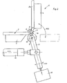
- Fig. 1 eine Ansicht einer Ausführungsform der Erfin- . dung, bei welcher an dem Antrieb einer Walze zum zusätzlichen Verformen der Außenseite eines Abstandhalter-Profiles zwei sich kreuzende Schwenkhebel vorgesehen sind, und
- Fig. 2 eine Ansicht einer abgewandelten Ausführungsform der Erfindung, bei welcher die Andrückvorrichtung für die Druckwalze unmittelbar in Längsrichtung an dem Schwenkhebel der Walze angreift.
- Fig. 1 is a view of an embodiment of the inven-. manure, in which two intersecting pivot levers are provided on the drive of a roller for additionally deforming the outside of a spacer profile, and
- Fig. 2 is a view of a modified embodiment of the invention, in which the pressing device for the pressure roller acts directly in the longitudinal direction on the pivot lever of the roller.
In beiden Ausführungsbeispielen weist eine im ganzen mit 1 bezeichnete Vorrichtung zum Biegen eines mit Trockenmittel gefüllten hohlen Abstandhalter-Profiles 2 eine in Zuführrichtung des Profiles 2 liegende Spannvorrichtung 3 und eine Vorrichtung 4 zum Erfassen des umzubiegenden Schenkels 2 a des Profiles 2 auf. Ferner gehört zu der Vorrichtung 1 ein Widerlager, im Ausführungsbeispiel ein Widerlagerdorn 5, zum Fixieren der Innenseite der entstehenden Krümmung 6. In beiden Zeichnungen ist der Biegevorgang, bei welchem der zu biegende Schenkel 2 a gegenüber dem ursprünglichen Verlauf des Profiles 2 um 90° gebogen wurde, gerade beendet.In both exemplary embodiments, a device designated as 1 for bending a
Wesentlich ist, daß während des Biegevorganges zumindest die Außenseite 7 der entstehenden Biegung 6 zusätzlich gewalzt wird. Dabei kann das im Inneren des hohlen Profiles 2 befindliche Trockenmittel während des Biegevorganges von der Außenseite der Biegung 6 her teilweise aus diesem Krümmungsbereich verdrängt und gleichzeitig die Profilaußenseite gestreckt, gelängt und ausgewalzt werden. Vor allem kann der Biegebereich 6 des Profiles 2 während des Biegevorganges mehrmals, insbesondere mit hoher Frequenz abwechselnd in der einen und der anderen Richtung seines Verlaufes gewalzt werden. Vor allem die - Profilaußenseite 7 wird also wie ein Kuchenteil ausgewalzt und erhält dadurch eine entsprechend größere Abmessung, die an der Außenseite der Biegung 6 erwünscht ist, damit das im Inneren befindliche, nur teilweise zu verdrängende Trockenmittel diese Außenseite des Profiles nicht durch die Biegung sprengt.It is essential that at least the outside 7 of the resulting
Man erkennt nun in beiden Ausführungsbeispielen eine mit ihrer Drehachse 8 parallel zur Biegeachse 9 liegende Druckwalze 10, die unter Anpreßdruck relativ zu der dem Biegedorn 5 abgewandten Außenseite 7 des Profiles 2 hin-und herbewegbar und dabei quer zu dieser Hin- und Herbewegung verschiebbar bzw. anpreßbar ist.One can now see in both exemplary embodiments a
Die Druckwalze 10 ist dazu am Ende eines Schwenkhebels 11 angeordnet, der für die Hin- und Herbewegung gemäß dem Doppelpfeil Pf 1 in Schwenkrichtung antreibbar ist, wobei zusätzlich eine in Richtung dieses Schwenkhebels 11 wirksame, im folgenden noch näher zu beschreibende Vorrichtung zum Andrücken der Druckwalze 10 vorgesehen ist. Diese Andrückvorrichtung ermöglicht einen gewissen Vorschub der Druckwalze 10 in Richtung des sie tragenden Schwenkhebels 11, damit vor allem bei der immer stärker werdenden Krümmung eine Anpassung an diese Zurückweichung - des zu bearbeitenden Werkstückes unter Aufrechterhaltung des erforderlichen Anpreßdruckes möglich ist. Dabei kann beispielsweise ein Profilbereich von etwa 2 cm Länge oder weniger, vorzugsweise von etwa einem cm Länge gewalzt werden. Man erkennt in den Figuren, daß der Profilbereich der Außenseite 7 der Krümmung 6 gewalzt wird, der vor dem eigentlichen Scheitel 12 der späteren fertigen Biegung 6 beginnt und etwa bis zu diesem Scheitel 12 oder vorzugsweise kurz dahinter reicht. Dadurch wird immer wieder Material in den Bereich gedrängt und gewalzt, der durch die Biegebewegung gemäß dem Pfeil Pf 2 - etwas in Richtung des Profiles 2 fließen soll.The
In beiden Ausführungsbeispielen greift für die Hin- und Herbewegung des die Walze 10 tragenden Schwenkhebels 11 ein Arbeitszylinder 13 quer zu dem Hebel 11 an diesem außerhalb seines Schwenkpunktes 14 an. Dabei sind derartige pneumatische oder hydraulische Arbeitszylinder bekannt, die mit der gewünschten hohen Frequenz umsteuerbar sind, um die schnelle Hin- und Herbewegung von z. B. 10 bis 40 z. B. 30 Walzbewegungen pro Sekunde durchführen zu können.In both exemplary embodiments, for the back and forth movement of the
Im Ausführungsbeispiel nach Fig. 1 greift an dem Schwenkhebel 11 ein zweiter Schwenkhebel 15 an, dessen Schwenkrichtung im wesentlichen in Richtung des die Walze 10 tragenden ersten Schwenkhebels 11 orientiert ist, der das Schwenklager 14 dieses ersten Schwenkhebels 11 prägt und an welchem ein Verstellelement 16, vorzugsweise ein weiterer Druckzylinder od. dgl. angreift. Die beiden Schwenkhebel 11 und 15 kreuzen sich also und sind in ihrem Kreuzungspunkt, nämlich dem Schwenklager 14, gegeneinander schwenkbar. Das Verstellelement 16 ist im Ausführungsbeispiel ein Arbeits- und Druckzylinder und greift an einem Ende des zweiten Hebels 15 an, während dieser zweite Schwenkhebel 15 seinerseits um einen Punkt 17 schwenkbar gelagert ist, der dem Angriff dieses Druckzylinders 16 an dem Kreuzungspunkt 14 gegenüberliegt.In the exemplary embodiment according to FIG. 1, a
Im Ausführungsbeispiel gemäß Fig. 2 greift der Druckzylinder 16 unmittelbar an dem der Walze 10 gegenüberliegenden Ende des Schwenkhebels 11 an, während der die Hin- und Herbewegung des Schwenkhebels 11 erzeugende Arbeitszylinder 13 seinerseits schwenkbar zwischen der Walze 10 und diesem Druckzylinder 16 beispielsweise etwa in der Mitte angreift.In the exemplary embodiment according to FIG. 2, the
Die Abstände zwischen der Schwenklagerung 17 und dem Angriff des Verstellelementes 16 sind im Ausführungsbeispiel nach Fig. 1 für eine Druckübersetzung etwa 2:1 im Sinne einer'Druckverstärkung gewählt. Somit kann durch die konstruktive Ausgestaltung der Fig. 1 eine Druckübersetzung erzielt werden, während im Ausführungsbeispiel nach Fig. 2 auf eine solche Druckübersetzungsmöglichkeit im Interesse einer möglichst einfachen konstruktiven Ausbildung verzichtet ist.The distances between the pivot bearing 17 and the attack of the adjusting
Es wurde schon das dornförmige Widerlager 5 erwähnt, um welches das Profil 2 biegbar ist. Dieses Widerlager 5 kann gleichzeitig das innere Ende einer um seine Mitte 9 schwenkbaren Klappe 18 bilden, die während des Biegevorganges an der Innenseite des zu biegenden Schenkels 2 a anliegt und diesen zusammen mit dem außeren Biegewerkzeug 4 ausrichtet und geradehält. An der Oberseite des Dornes 5 ist in nicht näher dargestellter Weise ein die Seitenfläche des Profiles 2 übergreifender Anschlag vorgesehen, der in diesem Bereich Ausbeulungen verhindern kann. Dieser Anschlag kann dabei rechtwinklig zu der Seitenfläche bewegbar sein, um sie nach dem Biegevorgang gut freigeben zu können.The mandrel-shaped
In Vorschubrichtung des Profiles 2 vor der Biegestelle ist die Spannvorrichtung vorgesehen, deren bewegliche Spannbacke 3 von außen her gegen die Seite des Profiles anpreßbar ist, deren Fortsetzung die Außenseite 7 der herzustellenden Biegung 6 bildet. Auf der Innenseite ist ein entsprechendes Widerlager 19 vorgesehen. Gegebenenfalls kann die Spannbacke 3 zusätzlich zu ihrer Bewegung rechtwinklig zu dem Profil 2 eine Klemmbewegung gegen die Unterlage des Profiles 2 durchführen und dabei den Rand des Profiles 2 übergreifen, um die Fixierung und Ausrichtung zu verbessern.In the direction of advance of the
Insbesondere für nach innen gerichtete Flansche aufweisende Profile 2 kann ein Auswerfer 20 vorgesehen sein, dessen Stößel 21 vorzugsweise im Bereich der Innenseite der durch den Biegevorgang hergestellten Krümmung am Profil angreifen kann, wenn die Biegung vollendet ist und das Walzwerkzeug sowie die Spannbacke und Biegewerkzeug aus dem Profilbereich genügend weit entfernt sind.In particular for
Es sei noch erwähnt, daß die Walzfrequenz und/oder die Andrückkraft so gewählt und eingestellt werden können, daß unterschiedliche Profilstärken, Werkstoffe u. dgl. berücksichtigt werden können, so daß gegebenenfalls nicht nur Aluminium-Profile, sondern auch Stahlprofile in der erfindungsgemäßen Weise gebogen werden können.It should also be mentioned that the rolling frequency and / or the pressing force can be selected and adjusted so that different profile thicknesses, materials and. Like. Can be taken into account so that not only aluminum profiles, but also steel profiles can be bent in the manner according to the invention.
Statt der beschriebenen Ausführungsbeispiele, bei denen eine zusätzliche Verformung an der Außenseite 7 der Biegung 6 eines zu biegenden Profiles 2 mit Hilfe einer Walze 10 erfolgt, ist auch eine andere zusätzliche plastische Verformung und Längung in diesem Bereich während des Biegevorganges möglich. Beispielsweise könnte die Außenseite 7 der Biegung 6 zumindest während des Biegevorganges gehämmert oder mittels eines Gleitstückes geknetet oder gerollt oder auf sonstige Weise mechanisch unter einen entsprechenden Druck gesetzt werden. Demgemäß könnte als Werkzeug zum Längen der Außenseite 7 der Biegung 6 ein Schlagwerkzeug, vorzugsweise ein entlang der Biegung 6 verschiebbares Schlagwerkzeug, oder ein andrückbares Gleitstück, Knetwerkzeug od. dgl. vorgesehen sein. Dabei würde dann also ähnlich wie bei den vorbeschriebenen Ausführungsbeispielen einerseits die Außenseite von diesem Werkzeug beaufschlagt, welches an-' dererseits entlang der Biegung 6 verschoben wird. Bevorzugt ist jedoch ein rollbares oder walzbares Werkzeug entsprechend der vorbeschriebenen Walze 10, weil dadurch eine stetige Materialverdrängung bei gleichzeitig möglichst geringem Widerstand gegen die erwähnte Vorschubbewegung erzielt wird.Instead of the exemplary embodiments described, in which an additional deformation takes place on the
Anstelle des Arbeitszylinders 13 können auch andere Verstellelemente an dem Schwenkhebel 11 angreifen, z. B. ein Elektro- oder Pneumatikmotor mit einer entsprechenden Schub- oder Zugstange oder einer Art Pleuelstange. Ferner ist es möglich, daß ein Verstellmotor unmittelbar am Schwenkpunkt 14 an dem Hebel 11 angreift, um diesen in der vorbeschriebenen Weise zu bewegen.Instead of the working
Alle in der Beschreibung, den Ansprüchen, der Zusammenfassung und der Zeichnung dargestellten Merkmale und Konstruktionsdetails können sowohl einzeln als auch in beliebiger Kombination miteinander wesentliche Bedeutung haben.All features and construction details shown in the description, the claims, the summary and the drawing can have significant meaning both individually and in any combination with one another.
Claims (24)
Priority Applications (1)
| Application Number | Priority Date | Filing Date | Title |
|---|---|---|---|
| AT84103516T ATE32313T1 (en) | 1983-04-09 | 1984-03-30 | METHOD AND DEVICE FOR BENDING SPACER PROFILES FOR INSULATING GLASS PANES. |
Applications Claiming Priority (2)
| Application Number | Priority Date | Filing Date | Title |
|---|---|---|---|
| DE19833312764 DE3312764A1 (en) | 1983-04-09 | 1983-04-09 | METHOD AND DEVICE FOR BENDING SPACER PROFILES FOR INSULATING GLASS PANELS |
| DE3312764 | 1983-04-09 |
Publications (3)
| Publication Number | Publication Date |
|---|---|
| EP0121873A2 true EP0121873A2 (en) | 1984-10-17 |
| EP0121873A3 EP0121873A3 (en) | 1985-10-09 |
| EP0121873B1 EP0121873B1 (en) | 1988-02-03 |
Family
ID=6195825
Family Applications (1)
| Application Number | Title | Priority Date | Filing Date |
|---|---|---|---|
| EP84103516A Expired EP0121873B1 (en) | 1983-04-09 | 1984-03-30 | Method and apparatus for bending spacekeeping profiles for thermopane glasses |
Country Status (3)
| Country | Link |
|---|---|
| EP (1) | EP0121873B1 (en) |
| AT (1) | ATE32313T1 (en) |
| DE (2) | DE3312764A1 (en) |
Cited By (15)
| Publication number | Priority date | Publication date | Assignee | Title |
|---|---|---|---|---|
| FR2605915A1 (en) * | 1986-11-03 | 1988-05-06 | Lisec Peter | DEVICE FOR FORMING A CORNER IN FLEXIBLE CUTTERS ATTACHED TO A GLASS PLATE |
| EP0318748A2 (en) * | 1987-12-03 | 1989-06-07 | Franz Xaver Bayer Isolierglasfabrik KG | Apparatus for bending a hollow profile, in particular a frame of spacekeeping profiles for insulating glass panes |
| WO1989007495A1 (en) * | 1988-02-15 | 1989-08-24 | Claus Roulund | A method for bending spacer profiles for insulating glass, an apparatus for carrying out the method, and a spacer profile made by the method |
| US4947537A (en) * | 1988-06-30 | 1990-08-14 | Peter Lisec | Process and apparatus for filling hollow moldings |
| EP0459971A1 (en) * | 1990-05-21 | 1991-12-04 | Peter Lisec | Method and apparatus for obtaining curved parts in hollow section strips |
| EP0462961A1 (en) * | 1990-05-21 | 1991-12-27 | Peter Lisec | Apparatus for bending hollow spaces frames |
| EP0483044A2 (en) * | 1990-10-26 | 1992-04-29 | Franz Xaver Bayer Isolierglasfabrik KG | A bending machine |
| US5243844A (en) * | 1990-05-21 | 1993-09-14 | Peter Lisec | Process for producing curved sections in hollow profile strips |
| EP0894553A2 (en) * | 1997-08-02 | 1999-02-03 | Franz Xaver Bayer Isolierglasfabrik Kg | Apparatus for bending a hollow profile with a clamp |
| EP0983809A2 (en) | 1998-08-29 | 2000-03-08 | Bayer Isolierglas- und Maschinentechnik GmbH | Method and device for bending a hollow profile for making a spacer frame for insulating glazing |
| AT410909B (en) * | 2000-05-09 | 2003-08-25 | Lisec Peter | Hollow strip bending process involves supporting hollow strip both internally and externally during bending |
| US6619098B2 (en) | 2001-08-28 | 2003-09-16 | Peter Lisec | Process and device for bending of hollow profile strips into spacer frames for insulating glass panes |
| EP1393831A2 (en) * | 2002-08-02 | 2004-03-03 | Lenhardt Maschinenbau GmbH | Apparatus for bending hollow profiles |
| CN102248041A (en) * | 2010-05-17 | 2011-11-23 | 赵士平 | Locating device in hollow glass aluminium division bar bender |
| AT514109A1 (en) * | 2013-04-12 | 2014-10-15 | Progress Maschinen & Automation Ag | bending machine |
Families Citing this family (7)
| Publication number | Priority date | Publication date | Assignee | Title |
|---|---|---|---|---|
| DE3523025A1 (en) * | 1985-06-27 | 1987-01-02 | Siemens Ag | Method and apparatus for bending elongated metallic workpieces |
| DE3740922A1 (en) * | 1987-12-03 | 1989-06-22 | Bayer Isolierglasfab Kg | METHOD AND DEVICE FOR PRODUCING A SPACER FRAME |
| DE3807529A1 (en) * | 1988-03-08 | 1989-09-21 | Bayer Isolierglasfab Kg | METHOD AND DEVICE FOR BENDING HOLLOW SPACER PROFILES |
| DE3942809A1 (en) * | 1989-12-23 | 1991-06-27 | Bayer Isolierglasfab Kg | METHOD AND DEVICE FOR PRODUCING A SPACER FRAME, IN PARTICULAR FOR INSULATING GLASS PANELS |
| DE4225833C2 (en) * | 1992-08-05 | 1994-07-28 | Bayer Isolierglasfab Kg | Bending device for hollow profiles |
| DE19839735B4 (en) * | 1998-09-01 | 2005-03-03 | Franz Xaver Bayer Isolierglasfabrik Kg | Device for bending a spacer-holding inner frame for an insulating glass pane |
| DE19956046B4 (en) * | 1999-11-22 | 2004-12-30 | Bayer Isolierglas- Und Maschinentechnik Gmbh | Method and device for producing a spacer frame for insulating glass panes |
Citations (6)
| Publication number | Priority date | Publication date | Assignee | Title |
|---|---|---|---|---|
| GB624169A (en) * | 1944-11-21 | 1949-05-30 | Sncase | Improvements in machines for bending angle and other metal rods, bars or the like |
| FR83512E (en) * | 1962-12-05 | 1964-08-28 | Method and machine according to this method for bending tubes with a large diameter | |
| FR1479220A (en) * | 1964-06-12 | 1967-05-05 | Tube bending machine | |
| CH598878A5 (en) * | 1975-08-14 | 1978-05-12 | Stoecklin Walter Ag | Bending machine for ribbed circular sections |
| FR2428728A1 (en) * | 1978-06-14 | 1980-01-11 | Bfg Glassgroup | PROCESS AND DEVICE FOR MANUFACTURING MULTIPLE GLAZING AND MULTIPLE GLASS THUS OBTAINED |
| GB2114201A (en) * | 1982-01-21 | 1983-08-17 | Peter Lisec | Spacer frame for double glazing units |
Family Cites Families (3)
| Publication number | Priority date | Publication date | Assignee | Title |
|---|---|---|---|---|
| DE2714782A1 (en) * | 1977-04-02 | 1978-10-05 | Bertrams Ag | Bender for thin-wall pipes - has mandrel built up from discs to fit in bend during external working by rollers |
| DE2829444C2 (en) * | 1978-07-05 | 1986-07-10 | Julius & August Erbslöh GmbH + Co, 5620 Velbert | Method and device for producing a spacer frame for multiple-pane insulating glass |
| DE2924461C2 (en) * | 1979-06-18 | 1982-03-04 | Bertrams Ag, 5900 Siegen | Device for the production of pipe elbows |
-
1983
- 1983-04-09 DE DE19833312764 patent/DE3312764A1/en not_active Withdrawn
-
1984
- 1984-03-30 EP EP84103516A patent/EP0121873B1/en not_active Expired
- 1984-03-30 DE DE8484103516T patent/DE3469138D1/en not_active Expired
- 1984-03-30 AT AT84103516T patent/ATE32313T1/en not_active IP Right Cessation
Patent Citations (6)
| Publication number | Priority date | Publication date | Assignee | Title |
|---|---|---|---|---|
| GB624169A (en) * | 1944-11-21 | 1949-05-30 | Sncase | Improvements in machines for bending angle and other metal rods, bars or the like |
| FR83512E (en) * | 1962-12-05 | 1964-08-28 | Method and machine according to this method for bending tubes with a large diameter | |
| FR1479220A (en) * | 1964-06-12 | 1967-05-05 | Tube bending machine | |
| CH598878A5 (en) * | 1975-08-14 | 1978-05-12 | Stoecklin Walter Ag | Bending machine for ribbed circular sections |
| FR2428728A1 (en) * | 1978-06-14 | 1980-01-11 | Bfg Glassgroup | PROCESS AND DEVICE FOR MANUFACTURING MULTIPLE GLAZING AND MULTIPLE GLASS THUS OBTAINED |
| GB2114201A (en) * | 1982-01-21 | 1983-08-17 | Peter Lisec | Spacer frame for double glazing units |
Cited By (22)
| Publication number | Priority date | Publication date | Assignee | Title |
|---|---|---|---|---|
| FR2605915A1 (en) * | 1986-11-03 | 1988-05-06 | Lisec Peter | DEVICE FOR FORMING A CORNER IN FLEXIBLE CUTTERS ATTACHED TO A GLASS PLATE |
| EP0318748A2 (en) * | 1987-12-03 | 1989-06-07 | Franz Xaver Bayer Isolierglasfabrik KG | Apparatus for bending a hollow profile, in particular a frame of spacekeeping profiles for insulating glass panes |
| EP0318748A3 (en) * | 1987-12-03 | 1990-06-13 | Franz Xaver Bayer Isolierglasfabrik Kg | Apparatus for bending a hollow profile, in particular a frame of spacekeeping profiles for insulating glass panes |
| WO1989007495A1 (en) * | 1988-02-15 | 1989-08-24 | Claus Roulund | A method for bending spacer profiles for insulating glass, an apparatus for carrying out the method, and a spacer profile made by the method |
| US4947537A (en) * | 1988-06-30 | 1990-08-14 | Peter Lisec | Process and apparatus for filling hollow moldings |
| US5243844A (en) * | 1990-05-21 | 1993-09-14 | Peter Lisec | Process for producing curved sections in hollow profile strips |
| EP0462961A1 (en) * | 1990-05-21 | 1991-12-27 | Peter Lisec | Apparatus for bending hollow spaces frames |
| US5117669A (en) * | 1990-05-21 | 1992-06-02 | Peter Lisec | Apparatus for bending hollow profile strips |
| EP0459971A1 (en) * | 1990-05-21 | 1991-12-04 | Peter Lisec | Method and apparatus for obtaining curved parts in hollow section strips |
| EP0483044A2 (en) * | 1990-10-26 | 1992-04-29 | Franz Xaver Bayer Isolierglasfabrik KG | A bending machine |
| EP0483044A3 (en) * | 1990-10-26 | 1992-07-08 | Rolltech A/S | A bending machine |
| EP0894553A2 (en) * | 1997-08-02 | 1999-02-03 | Franz Xaver Bayer Isolierglasfabrik Kg | Apparatus for bending a hollow profile with a clamp |
| EP0894553A3 (en) * | 1997-08-02 | 1999-08-25 | Franz Xaver Bayer Isolierglasfabrik Kg | Apparatus for bending a hollow profile with a clamp |
| US6023956A (en) * | 1997-08-02 | 2000-02-15 | Franz Xaver Bayer Isolierglasfabrik Kg | Device for bending a hollow section with a hold down clamp |
| EP0983809A2 (en) | 1998-08-29 | 2000-03-08 | Bayer Isolierglas- und Maschinentechnik GmbH | Method and device for bending a hollow profile for making a spacer frame for insulating glazing |
| AT410909B (en) * | 2000-05-09 | 2003-08-25 | Lisec Peter | Hollow strip bending process involves supporting hollow strip both internally and externally during bending |
| US6619098B2 (en) | 2001-08-28 | 2003-09-16 | Peter Lisec | Process and device for bending of hollow profile strips into spacer frames for insulating glass panes |
| EP1393831A2 (en) * | 2002-08-02 | 2004-03-03 | Lenhardt Maschinenbau GmbH | Apparatus for bending hollow profiles |
| EP1393831A3 (en) * | 2002-08-02 | 2004-11-03 | Lenhardt Maschinenbau GmbH | Apparatus for bending hollow profiles |
| CN102248041A (en) * | 2010-05-17 | 2011-11-23 | 赵士平 | Locating device in hollow glass aluminium division bar bender |
| AT514109A1 (en) * | 2013-04-12 | 2014-10-15 | Progress Maschinen & Automation Ag | bending machine |
| AT514109B1 (en) * | 2013-04-12 | 2015-02-15 | Progress Maschinen & Automation Ag | bending machine |
Also Published As
| Publication number | Publication date |
|---|---|
| EP0121873A3 (en) | 1985-10-09 |
| ATE32313T1 (en) | 1988-02-15 |
| EP0121873B1 (en) | 1988-02-03 |
| DE3469138D1 (en) | 1988-03-10 |
| DE3312764A1 (en) | 1984-10-18 |
Similar Documents
| Publication | Publication Date | Title |
|---|---|---|
| EP0121873B1 (en) | Method and apparatus for bending spacekeeping profiles for thermopane glasses | |
| DE3740921C2 (en) | ||
| DE2948115A1 (en) | METHOD AND DEVICE FOR SHAPING A SEAMING TUBES OF ARC-SHAPED CROSS-SECTION MADE OF FLAT MATERIAL, IN PARTICULAR SHEET | |
| CH659962A5 (en) | MACHINE FOR MAKING A CLEARANCE INTERIOR FRAME FOR AN INSULATED GLASS DISC. | |
| DE2642743C3 (en) | Device for manufacturing a motor vehicle axle | |
| EP3031547A1 (en) | Method and device for creating a corner connection | |
| DE2930191A1 (en) | DEVICE FOR SHAPING AND CLOSING FOLDING BOXES | |
| DE2757886A1 (en) | Corner connection for metal door frame - has sections of tubes punched in cut=outs in corner pieces | |
| DE19956046B4 (en) | Method and device for producing a spacer frame for insulating glass panes | |
| DE3231698A1 (en) | Method for forming the corners of spacer frames for insulating glass, and an apparatus for carrying it out | |
| DE2341857B1 (en) | Tool arrangement for making pipe arches | |
| DE2252920A1 (en) | Making hollow plastics section rapidly from sheet - all edge lines are marked simultaneously then sides bent up simultaneously to close section | |
| DE3120897A1 (en) | Press for producing beams or sheets from glued rods | |
| DE2015414A1 (en) | Joining hollow sections to form window frames etc | |
| EP1281457B1 (en) | Device for bending hollow section bars | |
| CH673604A5 (en) | ||
| DE102011080703A1 (en) | A frame press for joining pre-folded frame profiles to a casement of a window, a door or the like, as well as a method for producing such a casement | |
| WO1999007540A1 (en) | Method for bending closed hollow sections using the support of a medium | |
| DE1479275B2 (en) | Method and device for separating pieces of waste in the manufacture of hollow bodies made of thermoplastic material in the blow molding process | |
| DE3707572A1 (en) | Pneumatically actuated welding tongs for electrical resistance spot welding | |
| DE102004060805A1 (en) | Hollow section bar e.g. spacer frame, bending device for insulating glass plate, has bending tool with rolls rotated parallel to each other, where shell of one roll has projecting section in center of its section facing outer wall of bar | |
| DE1761372C3 (en) | Punching tool | |
| DE3246988A1 (en) | Method for shaping the corners of spacer frames for insulating glass and tool for carrying it out | |
| DE102020128163B3 (en) | Mold and process for the extrusion of metallic materials | |
| DE4315706C2 (en) | Press brakes to form fold grooves on sheet metal profiles |
Legal Events
| Date | Code | Title | Description |
|---|---|---|---|
| PUAI | Public reference made under article 153(3) epc to a published international application that has entered the european phase |
Free format text: ORIGINAL CODE: 0009012 |
|
| AK | Designated contracting states |
Designated state(s): AT BE CH DE FR GB IT LI LU NL SE |
|
| PUAL | Search report despatched |
Free format text: ORIGINAL CODE: 0009013 |
|
| AK | Designated contracting states |
Designated state(s): AT BE CH DE FR GB IT LI LU NL SE |
|
| 17P | Request for examination filed |
Effective date: 19851017 |
|
| 17Q | First examination report despatched |
Effective date: 19860910 |
|
| ITF | It: translation for a ep patent filed |
Owner name: ING. ZINI MARANESI & C. S.R.L. |
|
| GRAA | (expected) grant |
Free format text: ORIGINAL CODE: 0009210 |
|
| AK | Designated contracting states |
Kind code of ref document: B1 Designated state(s): AT BE CH DE FR GB IT LI LU NL SE |
|
| REF | Corresponds to: |
Ref document number: 32313 Country of ref document: AT Date of ref document: 19880215 Kind code of ref document: T |
|
| REF | Corresponds to: |
Ref document number: 3469138 Country of ref document: DE Date of ref document: 19880310 |
|
| ET | Fr: translation filed | ||
| GBT | Gb: translation of ep patent filed (gb section 77(6)(a)/1977) | ||
| PG25 | Lapsed in a contracting state [announced via postgrant information from national office to epo] |
Ref country code: LU Free format text: LAPSE BECAUSE OF NON-PAYMENT OF DUE FEES Effective date: 19880331 |
|
| PLBE | No opposition filed within time limit |
Free format text: ORIGINAL CODE: 0009261 |
|
| STAA | Information on the status of an ep patent application or granted ep patent |
Free format text: STATUS: NO OPPOSITION FILED WITHIN TIME LIMIT |
|
| 26N | No opposition filed | ||
| PGFP | Annual fee paid to national office [announced via postgrant information from national office to epo] |
Ref country code: LU Payment date: 19900323 Year of fee payment: 7 |
|
| ITTA | It: last paid annual fee | ||
| EAL | Se: european patent in force in sweden |
Ref document number: 84103516.5 |
|
| PGFP | Annual fee paid to national office [announced via postgrant information from national office to epo] |
Ref country code: SE Payment date: 19990301 Year of fee payment: 16 |
|
| PGFP | Annual fee paid to national office [announced via postgrant information from national office to epo] |
Ref country code: BE Payment date: 19990308 Year of fee payment: 16 |
|
| PG25 | Lapsed in a contracting state [announced via postgrant information from national office to epo] |
Ref country code: SE Free format text: LAPSE BECAUSE OF NON-PAYMENT OF DUE FEES Effective date: 20000331 Ref country code: BE Free format text: LAPSE BECAUSE OF NON-PAYMENT OF DUE FEES Effective date: 20000331 |
|
| BERE | Be: lapsed |
Owner name: FRANZ XAVER BAYER ISOLIERGLASFABRIK K.G. Effective date: 20000331 |
|
| EUG | Se: european patent has lapsed |
Ref document number: 84103516.5 |
|
| PGFP | Annual fee paid to national office [announced via postgrant information from national office to epo] |
Ref country code: FR Payment date: 20010226 Year of fee payment: 18 |
|
| PGFP | Annual fee paid to national office [announced via postgrant information from national office to epo] |
Ref country code: NL Payment date: 20010331 Year of fee payment: 18 |
|
| REG | Reference to a national code |
Ref country code: GB Ref legal event code: IF02 |
|
| PGFP | Annual fee paid to national office [announced via postgrant information from national office to epo] |
Ref country code: GB Payment date: 20020829 Year of fee payment: 19 |
|
| PGFP | Annual fee paid to national office [announced via postgrant information from national office to epo] |
Ref country code: AT Payment date: 20020830 Year of fee payment: 19 |
|
| PGFP | Annual fee paid to national office [announced via postgrant information from national office to epo] |
Ref country code: CH Payment date: 20020920 Year of fee payment: 19 |
|
| PG25 | Lapsed in a contracting state [announced via postgrant information from national office to epo] |
Ref country code: NL Free format text: LAPSE BECAUSE OF NON-PAYMENT OF DUE FEES Effective date: 20021001 |
|
| PG25 | Lapsed in a contracting state [announced via postgrant information from national office to epo] |
Ref country code: FR Free format text: LAPSE BECAUSE OF NON-PAYMENT OF DUE FEES Effective date: 20021129 |
|
| NLV4 | Nl: lapsed or anulled due to non-payment of the annual fee |
Effective date: 20021001 |
|
| REG | Reference to a national code |
Ref country code: FR Ref legal event code: ST |
|
| PG25 | Lapsed in a contracting state [announced via postgrant information from national office to epo] |
Ref country code: GB Free format text: LAPSE BECAUSE OF NON-PAYMENT OF DUE FEES Effective date: 20030330 Ref country code: AT Free format text: LAPSE BECAUSE OF NON-PAYMENT OF DUE FEES Effective date: 20030330 |
|
| PG25 | Lapsed in a contracting state [announced via postgrant information from national office to epo] |
Ref country code: LI Free format text: LAPSE BECAUSE OF NON-PAYMENT OF DUE FEES Effective date: 20030331 Ref country code: CH Free format text: LAPSE BECAUSE OF NON-PAYMENT OF DUE FEES Effective date: 20030331 |
|
| PGFP | Annual fee paid to national office [announced via postgrant information from national office to epo] |
Ref country code: DE Payment date: 20030528 Year of fee payment: 20 |
|
| REG | Reference to a national code |
Ref country code: CH Ref legal event code: PL |
|
| GBPC | Gb: european patent ceased through non-payment of renewal fee |
Effective date: 20030330 |