EP0109905A1 - Apparatus for bending tubes - Google Patents
Apparatus for bending tubes Download PDFInfo
- Publication number
- EP0109905A1 EP0109905A1 EP19830402217 EP83402217A EP0109905A1 EP 0109905 A1 EP0109905 A1 EP 0109905A1 EP 19830402217 EP19830402217 EP 19830402217 EP 83402217 A EP83402217 A EP 83402217A EP 0109905 A1 EP0109905 A1 EP 0109905A1
- Authority
- EP
- European Patent Office
- Prior art keywords
- tube
- roller
- bending
- axis
- inner roller
- Prior art date
- Legal status (The legal status is an assumption and is not a legal conclusion. Google has not performed a legal analysis and makes no representation as to the accuracy of the status listed.)
- Granted
Links
Images

Classifications
-
- B—PERFORMING OPERATIONS; TRANSPORTING
- B21—MECHANICAL METAL-WORKING WITHOUT ESSENTIALLY REMOVING MATERIAL; PUNCHING METAL
- B21D—WORKING OR PROCESSING OF SHEET METAL OR METAL TUBES, RODS OR PROFILES WITHOUT ESSENTIALLY REMOVING MATERIAL; PUNCHING METAL
- B21D7/00—Bending rods, profiles, or tubes
- B21D7/08—Bending rods, profiles, or tubes by passing between rollers or through a curved die
Definitions
- the hydraulic brake control lines consist of relatively rigid sections of tubes, but having a certain malleability, comprising rectilinear parts connected by curved parts; these are generally left-hand pieces of which only the joint rectilinear parts are two by two in the same plane with the curved part which connects them; the ends of these tube sections are further provided with threaded connections, and shaped so that these connections cannot escape.
- the present invention relates to a machine capable of automatically manufacturing such pipes, whatever their type, dimensions and size, provided that it is provided with all the data corresponding to the desired pipe.
- Bending heads are known through which the tube to be bent arrives axially and passes between two bending rollers, of which an inner roller has a radius equal to the radius of curvature of the desired bending, and an outer roller, whose axis is rotatable around that of the fixed roller situated on a line passing through the axis of the internal roller and which, in the inactive position of the external roller, is perpendicular to the axis of the bending head along which the tube to be bent arrives, with means to rotate it around the axis of the inner roller by an angle equal to the angle at the center desired for this curved part.
- rollers preferably have peripheral grooves whose radius is substantially equal to the outside radius of the tubes to be bent, so that they are held peripherally and do not tend to collapse during their bending.
- the bending has a radius of curvature which is a function of the angle at the center of which the axis of the outer roller is rotated around that of the inner roller, and which decreases as the latter increases ; one can find by calculations or by tests, on the one hand, the angle which must rotate the axis of the outer roller around that of the inner roller to obtain a bending of a tube of determined outer diameter whose curve has the desired radius of curvature, and, on the other hand, the length which must advance the tube, and subject it to this bending without modifying the angular position of the outer roller, so that the curved part obtained has the angle at the desired center.
- the machine comprises a guide nozzle fixed to its front part, immediately behind the internal bending roller, so that it is traversed axially by the tube intended to be bent and that it s opposes the deformation thereof by reaction in opposite direction to that caused by its bending around the inner roller under the action of the outer roller.
- the machine must of course further include means for advancing the tube to be bent along the axis of its bending head in order to obtain, first, a first straight portion of the desired length, then an equal straight length to that of the contiguous curved part to be produced with a curve having the angle at the desired center, means for pivoting the bending head around the tube by the desired angle so that its working plane is that in which it must be located the contiguous curved part and the rectilinear part which will extend it, and means for pivoting the outer roller around the axis of the inner roller by an angle such that the curved part which it shapes by its rotation has the radius of curvature desired, said means continuing to intervene successively to produce each curved part and the straight part which extends it into the piping.
- Means can also be provided for cutting the tube below the pipe which has just been completed, and other means for shaping the two ends of the pipe and adapting the conventional threaded connections which it must include.
- the machine can be fed by rolls of tubes which can be from 2000 to 3000 meters in length, for example, which has a very great advantage for keeping these tubes in good condition, which deteriorate when they are cut in advance.
- the arrangement must be such that each of these means intervenes automatically, in turn, and for the time necessary to be able to execute the desired operation, as it has been programmed.
- the bending head shown in Figures 1 and 2 has an inner roller 1, rotatable about a fixed axis 2, and an outer roller 3, rotatable around an axis 4, which is itself pivotally mounted around the axis 2 of the inner roller 1; in the rest position shown, in which these rollers produce no bending, the line joining the axes 2 and 4 of the two rollers 1 and 3 is perpendicular to the axis of the tube 5 intended to be bent by the combined action of the two rollers 1 and 3 and which passes through said bending head.
- the motor 6 which, by means of the bevel gears 7 and 7a and the straight gears 8, 8a and 8b, drives the outer rack 9 in translation sleeve 10, parallel to tube 5; at the front part of this sleeve 10 are articulated the rear ends of two symmetrical connecting rods 11, the front ends of which are articulated on the lower part of a part 12, forming a yoke, the wings of which are rotatably mounted on the axis 2 of the inner roller l, and between which is mounted the axis 4 of the outer roller 3.
- the axis 4 of the movable roller 3 is at a distance from the axis 2 of the fixed roller 1 such that there remains between these rollers a slightly larger free space than the diameter of the tube 5; under these conditions, the bending of the tube 5 does not begin until the outer roller 3 comes into contact with the extension 5a of the tube 5, and ensures its bending with a radius of curvature which is a function of the angle which is made turn this outer roller 3 around the axis 2 of the inner roller 1; thus, as shown in Figure 3, when the outer roller 3 has arrived in position 3a, the straight extension of the tube 5 is first located at 5 " ' a; the tube 5 is tangent to the inner roller 1 and the outer roller 3 with a curved part whose center of curvature is O, on the lines joining the axes 2 and 4 of the rollers 1 and 3 at the points of tangency of the tube on these rollers; the corresponding radius of curvature decreases
- This curved part of the tube 5 is extended by its straight part 5 "a which tangents the outer roller 3; the angle at the center of this curved part is equal to that which the outer roller 3 has been made to pivot about the axis 2 of the inner roller 1; if we want to increase this angle at the center, it suffices to continue advancing the tube 5 through the bending head without modifying the position of the outer roller 3, until this angle reaches l 'desired amplitude; the straight extension of the bending tube is then in position 5 "' a.
- a guide nozzle 37 is fixed to its front part, immediately behind the internal bending roller 1, so that it is axially traversed by the tube 5 intended to be bent and that it s opposes the deformation of the latter by reaction in the opposite direction to that caused by its bending around the inner roller 1 under the action of the outer roller 3.
- the plane of this bending head can be modified at will because its active part 14 on which are mounted the inner 1 and outer 3 bending rollers, is itself rotatable inside the sliding sleeve 10, which itself is held in a fixed angular position by the plate 15, sliding in the frame 16 of the bending head and engaged in a longitudinal groove 17 provided for this purpose in the sleeve 10.
- the bending head shown further comprises a device for shearing the section of tube whose bending has just been completed; it is constituted by two knobs 21 integral in rotation with the pivoting part 14 and mounted, for this purpose, at the inner end of two pushers 22 forming yokes, sliding in corresponding radial bores 23 of the pivoting part 14; the outer edges 25 of these radial pushers 22 are inclined so as to constitute cams cooperating with the female conical surfaces 26 of the front part of the sliding annular part 27; to shear the tube 5, compressed air is made to penetrate through the orifice 28 into 1 "free space 29 provided between the frame 16 and the rear part of the sliding annular part 27, which causes the rearward sliding of this part 27, against a return spring, and, as a result, a centripetal force exerted on the pushers forming yokes 22, the two knobs 21 of which cut the tube, in particular if the pivoting part is driven 14 rotating at high speed by means of the motor 18.
- such a bending head 30 is mounted on the frame 31 with its three motors, 6 for controlling the pivoting of the axis 4 of the outer roller 3 around that of the inner roller 1 , the motor 18 which makes it possible to pivot the bending plane of the bending head 30 around the tube to be bent 5, and the motor 32 which drives the pairs of rollers 33 which cause the desired sliding of the tube 5 through the head of bending.
- the machine further comprises a retractable device 33 allowing, before the commencement of the operations of bending the tube 5, to present before the latter, at 34, a threaded connection coming from the supply ramp 35, in a manner known per se, through which the anterior end of said tube is engaged; a suitable device then shapes the front end of this tube so that this threaded connection can no longer escape forward.
- the rear end of the pipe section which has just been bent and separated, by shearing, from the tube of which it formed the front part, may likewise be provided with a threaded connection and be shaped so that it cannot escape backwards.
Abstract
Description
Les canalisations de commande des freins hydrauliques sont constituées de tronçons de tubes relativement rigides, mais présentant une certaine malléabilité, comportant des parties rectilignes raccordées par des parties courbes ; il s'agit généralement de pièces gauches dont seules les parties rectilignes conjointes sont deux à deux dans le même-plan avec la partie courbe qui les relie ; les extrémités de ces tronçons de tubes sont en outre munies de raccords filetés, et façonnées de façon que ces raccords ne puissent pas s'échapper.The hydraulic brake control lines consist of relatively rigid sections of tubes, but having a certain malleability, comprising rectilinear parts connected by curved parts; these are generally left-hand pieces of which only the joint rectilinear parts are two by two in the same plane with the curved part which connects them; the ends of these tube sections are further provided with threaded connections, and shaped so that these connections cannot escape.
Ces canalisations sont actuellement faites manuellement, au moyen de tronçons de tubes découpés à la lonqueur voulue, qui sont cintrés sur des gabarits appropriés ; c'est un travail relativement pénible, manquant parfois de précision, et qui nécessite d'avoir un nombre de gabarits égal à celui des différents types de canalisations à réaliser ; le moindre changement apporté à une canalisation exige la confection d'un nouveau qabarit.These pipes are currently made manually, by means of sections of tubes cut to the desired length, which are bent on appropriate templates; it is a relatively strenuous job, sometimes lacking in precision, and which requires having a number of templates equal to that of the different types of pipes to be made; the slightest change to a pipe requires the creation of a new qabarit.
La présente invention a pour objet une machine susceptible de fabriquer automatiquement de telles canalisations, quels qu'en soient le type, les dimensions et le gabarit, à condition qu'on lui fournisse toutes les données correspondantes à la canalisation désirée.The present invention relates to a machine capable of automatically manufacturing such pipes, whatever their type, dimensions and size, provided that it is provided with all the data corresponding to the desired pipe.
Ces canalisations sont généralement définies dans des tableaux donnant des coordonnées x, y, z dans l'espace de leurs différents points d'épure ; on appelle points d'épure d'une canalisation les points de rencontre des prolongements de chaque groupe de deux de leurs parties rectilignes conjointes réunies par une partie courbe et situées dans un même plan ; ces tableaux doivent également indiquer pour chaque point d'épure le rayon de courbure et l'angle au centre de la partie courbe considérée.These pipelines are generally defined in tables giving x, y, z coordinates in the space of their different sketch points; the points of the drawing of a pipe are the meeting points of the extensions of each group of two of their joint rectilinear parts joined by a curved part and situated in the same plane; these tables must also indicate for each point of sketch the radius of curvature and the angle at the center of the curved part considered.
On connaît des têtes de cintrage à travers lesquelles le tube à cintrer arrive axialement et passe entre deux galets de cintrage, dont un galet intérieur a un rayon égal au rayon de courbure du cintrage désiré, et un galet extérieur, dont l'axe est rotatif autour de celui du galet fixe situé sur une ligne passant par l'axe du galet intérieur et qui, en position inactive du galet extérieur, est perpendiculaire à l'axe de la tête de cintrage suivant lequel arrive le tube à cintrer, avec des moyens pour le faire pivoter autour de l'axe du galet intérieur d'un angle égal à l'angle au centre désiré pour cette partie courbe.Bending heads are known through which the tube to be bent arrives axially and passes between two bending rollers, of which an inner roller has a radius equal to the radius of curvature of the desired bending, and an outer roller, whose axis is rotatable around that of the fixed roller situated on a line passing through the axis of the internal roller and which, in the inactive position of the external roller, is perpendicular to the axis of the bending head along which the tube to be bent arrives, with means to rotate it around the axis of the inner roller by an angle equal to the angle at the center desired for this curved part.
Ces galets ont préférablement des gorges périphériques dont le rayon est sensiblement égal au rayon extérieur des tubes à cintrer, de façon que ceux-ci soient maintenus périphériquement et n'aient pas tendance à s'écraser au cours de leur cintrage.These rollers preferably have peripheral grooves whose radius is substantially equal to the outside radius of the tubes to be bent, so that they are held peripherally and do not tend to collapse during their bending.
Pour permettre de réaliser des canalisations gauches ayant des courbures dans des plans différents, on a également proposé antérieurement d'aménager de telles têtes de cintrage de façon qu'elles puissent pivoter à volonté autour de l'axe du tube destiné à être cintré et qui la traverse à cet effet, ce qui permet d'amener leur plan de travail dans une orientation quelconque, correspondant au gauchissement désiré.To make it possible to carry out left pipes having curvatures in different planes, it has also previously been proposed to arrange such bending heads so that they can pivot at will around the axis of the tube intended to be bent and which the crosspiece for this purpose, which allows to bring their work plan in any orientation, corresponding to the desired warping.
Toutefois, avec de tels agencements, on ne peut réaliser que des cintrages ayant un rayon de courbure égal à. celui du galet intérieur et il faut donc changer celui-ci, et également le galet extérieur quand on veut obtenir un rayon du cintrage différent.However, with such arrangements, it is only possible to produce bends having a radius of curvature equal to. that of the inner roller and it is therefore necessary to change it, and also the outer roller when we want to obtain a different bending radius.
Or on a trouvé, suivant une première caractéristique de la présente invention, qu'on pouvait réaliser avec de telles têtes de cintrage des courbes de rayons de courbure quelconques, pourvu qu'ils soient supérieurs à celui du rayon du galet intérieur, à condition de disposer l'axe du galet extérieur à une distance de celui du galet intérieur telle qu'ils laissent entre eux un espace légèrement supérieur au diamètre du tube à cintrer, de l'ordre de 1 mm par exemple.Now, it has been found, according to a first characteristic of the present invention, that it is possible to produce with such bending heads curves of any radius of curvature, provided that they are greater than that of the radius of the inner roller, provided that arrange the axis of the outer roller at a distance from that of the inner roller such that they leave between them a space slightly greater than the diameter of the tube to be bent, of the order of 1 mm for example.
Dans ce cas, le cintrage a un rayon de courbure qui est fonction de l'angle au centre dont on fait tourner l'axe du galet extérieur autour de celii du galet intérieur, et qui diminue au fur et à mesure que celui-ci augmente ; on peut trouver par des calculs ou par des essais, d'une part, l'angle dont il faut faire tourner l'axe du galet extérieur autour de celui du galet intérieur pour obtenir un cintrage d'un tube de diamètre extérieur déterminé dont la courbe a le rayon de courbure désiré, et, d'autre part, la longueur dont on doit faire avancer le tube, et la soumettre à ce cintrage sans modifier la position angulaire du galet extérieur, pour que la partie courbe obtenue ait l'angle au centre désiré.In this case, the bending has a radius of curvature which is a function of the angle at the center of which the axis of the outer roller is rotated around that of the inner roller, and which decreases as the latter increases ; one can find by calculations or by tests, on the one hand, the angle which must rotate the axis of the outer roller around that of the inner roller to obtain a bending of a tube of determined outer diameter whose curve has the desired radius of curvature, and, on the other hand, the length which must advance the tube, and subject it to this bending without modifying the angular position of the outer roller, so that the curved part obtained has the angle at the desired center.
Suivant une autre caractéristique de l'invention, la machine comporte une buse de guidage fixée à sa partie antérieure, immédiatement derrière le galet de cintrage intérieur, de façon qu'elle soit traversée axialement par le tube destiné à être cintré et qu'elle s'oppose à la déformation de celui-ci par réaction en sens inverse à celle provoquée par son cintrage autour du galet intérieur sous l'action du galet extérieur.According to another characteristic of the invention, the machine comprises a guide nozzle fixed to its front part, immediately behind the internal bending roller, so that it is traversed axially by the tube intended to be bent and that it s opposes the deformation thereof by reaction in opposite direction to that caused by its bending around the inner roller under the action of the outer roller.
On obtient ainsi une précision dans la position et le rayon des cintrages successifs qu'on ne pouvait atteindre avec les machines connues antérieurement ne comportant pas une telle base de guidage.This gives precision in the position and the radius of successive bends that could not be achieved with previously known machines not having such a guide base.
La machine doit bien entendu comporter en outre des moyens pour faire avancer le tube à cintrer suivant l'axe de sa tête de cintrage en vue d'obtenir, d'abord, une première partie rectiligne de la longueur voulue, puis une longueur rectiligne égale à celle de la partie cintrée contiguë à réaliser avec une courbe ayant l'angle au centre désiré, des moyens pour faire pivoter la tête de cintrage autour du tube de l'angle voulu pour que son plan de travail soit celui dans lequel devra se trouver la partie cintrée contiguë et la partie rectiligne qui la prolongera, et des moyens pour faire pivoter le galet extérieur autour de l'axe du galet intérieur d'un angle tel que la partie courbe qu'il façonne par sa rotation ait le rayon de courbure désiré, lesdits moyens continuant à intervenir successivement pour réaliser chaque partie courbe et la partie rectiligne qui la prolonge dans la tuyauterie.The machine must of course further include means for advancing the tube to be bent along the axis of its bending head in order to obtain, first, a first straight portion of the desired length, then an equal straight length to that of the contiguous curved part to be produced with a curve having the angle at the desired center, means for pivoting the bending head around the tube by the desired angle so that its working plane is that in which it must be located the contiguous curved part and the rectilinear part which will extend it, and means for pivoting the outer roller around the axis of the inner roller by an angle such that the curved part which it shapes by its rotation has the radius of curvature desired, said means continuing to intervene successively to produce each curved part and the straight part which extends it into the piping.
Des moyens peuvent aussi être prévus pour tronçonner le tube en deçà de la canalisation qui vient d'être terminée, et d'autres moyens pour façonner les deux extrémités de la canalisation et y adapter les raccords filetés classiques qu'elle doit comporter.Means can also be provided for cutting the tube below the pipe which has just been completed, and other means for shaping the two ends of the pipe and adapting the conventional threaded connections which it must include.
La machine .peut être alimentée par des rouleaux de tubes qui peuvent avoir de 2000 à 3000 mètres de longueur, par exemple, ce qui présente un très grand avantage pour la conservation en bon état de ces tubes, qui se détériorent quand ils sont tronçonnés à l'avance.The machine can be fed by rolls of tubes which can be from 2000 to 3000 meters in length, for example, which has a very great advantage for keeping these tubes in good condition, which deteriorate when they are cut in advance.
L'agencement doit être tel que chacun de ces moyens intervienne automatiquement, à tour de rôle, et pendant le temps nécessaire pour pouvoir exécuter l'opération désirée, telle qu'elle a été programmée.The arrangement must be such that each of these means intervenes automatically, in turn, and for the time necessary to be able to execute the desired operation, as it has been programmed.
Le dessin annexé montre à titre d'exemple un mode de réalisation d'une machine suivant la présente invention.
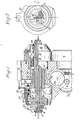
- La figure 1 est une vue,partie en coupe et partie en élévation,d'une tête de cintrage susceptible d'être utilisée dans cette machine.
- La figure 2 est une vue en bout avec partie en coupe.
- La figure 3 est un croquis explicatif.
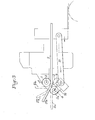
- La figure 4 montre l'ensemble d'une telle machine.
- Figure 1 is a view, partly in section and partly in elevation, of a bending head capable of being used in this machine.
- Figure 2 is an end view with part in section.
- Figure 3 is an explanatory sketch.
- Figure 4 shows the assembly of such a machine.
La tête de cintrage représentée aux figures 1 et 2 comporte un galet intérieur 1, rotatif autour d'un axe fixe 2, et un galet extérieur 3,rotatif autour d'un axe 4,qui est lui-même monté pivotant autour de l'axe 2 du galet intérieur 1 ; dans la position de repos représentée, dans laquelle.ces galets ne produisent aucun cintrage, la ligne joignant les axes 2 et 4 des deux galets 1 et 3 est perpendiculaire à l'axe du tube 5 destiné à être cintré par l'action conjuguée des deux galets 1 et 3 et qui traverse ladite tête de cintrage.The bending head shown in Figures 1 and 2 has an
Pour cintrer ce tube au moyen des deux galets intérieur 1 et extérieur 3, on utilise le moteur 6 qui, par l'intermédiaire des pignons coniques 7 et 7a et des pignons droits 8, 8a et 8b, entraîne en translation la crémaillère extérieure 9 du manchon 10, parallèlement au tube 5 ; à la partie antérieure de ce manchon 10 sont articulées les extrémités arrière de deux bielles symétriques 11, dont les extrémités avant sont articulées sur la partie inférieure d'une pièce 12, formant chape, dont les ailes sont montées rotatives sur l'axe 2 du galet intérieur l,et entre lesquelles est monté l'axe 4 du galet extérieur 3.To bend this tube by means of the two inner 1 and outer 3 rollers, the
Lorsque le galet extérieur 3 est en position de repos,avec son axe-4 symétrique de l'axe 2 du galet intérieur 1 par rapport au tube 5, celui-ci peut passer entre ces galets sans être cintré, et son extrémité antérieure 5a reste donc rectiligne.When the
S'il n'existait aucun jeu entre les galets 1 et 3,la rotation du galet mobile 3 autour de l'axe 2 du galet fixe 1 provoquerait l'enroulement de celui-ci sur ledit galet l,avec un rayon de courbure égal à celui du galet 1, et son prolongement la serait donc tangent audit galet 1 comme le montre la figure 3.If there was no play between the
Pour pouvoir faire varier ce rayon de courbure, suivant la présente invention, l'axe 4 du galet mobile 3 est à une distance de l'axe 2 du galet fixe 1 tel qu'il reste entre ces galets un espace libre légèrement plus grand que le diamètre du tube 5 ; dans ces conditions, le cintrage du tube 5 ne commence qu'au moment où le galet extérieur 3 arrive au contact du prolongement 5a du tube 5, et en assure le cintrage avec un rayon de courbure qui est fonction de l'angle dont on fait tourner ce galet extérieur 3 autour de l'axe 2 du galet intérieur 1 ; c'est ainsi que, comme montré dans la figure 3, lorsque le galet extérieur 3 est arrivé dans la position 3a, le prolongement rectiligne du tube 5 se trouve d'abord en 5"'a ; le tube 5 est tangent au galet intérieur 1 et au galet extérieur 3 avec une partie courbe dont le centre de courbure est en O, sur les lignes joignant les axes 2 et 4 des galets 1 et 3 aux points de tangence du tube sur ces galets ; le rayon de courbure correspondant diminue quand croît l'angle de rotation du galet extérieur autour de l'axe 2 du galet intérieur 1.To be able to vary this radius of curvature, according to the present invention, the
Cette partie courbe du tube 5 est prolongée par sa partia rectiligne 5"a qui tangente le galet extérieur 3 ; l'angle au centre de cette partie courbe est égal à celui dont on a fait pivoter le galet extérieur 3 autour de l'axe 2 du galet intérieur 1 ; si l'on veut augmenter cet angle au centre, il suffit de continuer à faire avancer le tube 5 à travers la tête de cintrage sans modifier la position du galet extérieur 3, jusqu'à ce que cet angle atteigne l'amplitude désirée ; le prolongement rectiligne du tube de cintrage se trouve alors dans la position 5"'a.This curved part of the
On voit donc qu'avec un tel dispositif, on peut obtenir des cintrages d'un rayon de courbure quelconque, à condition qu'il soit supérieur à celui du rayon du galet intérieur 1, et avec des angles au centre de ces courbures également quelconque.It can therefore be seen that with such a device, it is possible to obtain bends of any radius of curvature, provided that it is greater than that of the radius of the
Suivant une autre caractéristique de l'invention, une buse deguidage 37 est fixée à sa partie antérieure, immédiatement derrière le galet de cintrage intérieur 1, de façon qu'elle soit traversée axialement par le tube 5 destiné à être cintré et qu'elle s'oppose à la déformation dé celui-ci par réaction en sens inverse à celle provoquée par son cintrage autour du galet intérieur 1 sous l'action du galet extérieur 3. Le plan de cette tête de cintrage peut être modifié à volonté du fait que sa partie active 14 sur laquelle sont montés les galets de cintrage intérieur 1 et extérieur 3, est elle-même rotative à l'intérieur du manchon coulissant 10, qui lui-même est maintenu dans une position angulaire fixe par la plaquette 15, coulissant dans le bâti 16 de la tête de cintrage et engagée dans une rainure longitudinale 17 prévue à cet effet dans le manchon 10.According to another characteristic of the invention, a
Le pivotement de cette tête de cintrage autour de son axe, pour faire varier à volonté le plan de cintrage, peut être commandé par un moteur 18 qui entraîne en rotation le manchon dentelé intérieurement 19, en prise avec la dentelure 20 du prolongement vers l'extérieur 13 du porte-galets 14.The pivoting of this bending head about its axis, to vary the bending plane at will, can be controlled by a
La tête de cintrage représentée comporte en outre un dispositif permettant de cisailler le tronçon de tube dont le cintrage vient d'être achevé ; il est constitué par deux mollettes 21 solidaires en rotation de la pièce pivotante 14 et montées, à cet effet, à l'extrémité intérieure de deux poussoirs 22 formant chapes, coulissant dans des alésages radiaux 23 correspondant de la pièce pivotante 14 ; les bords extérieurs 25 de ces poussoirs radiaux 22 sont inclinés de façon à constituer des cames coopérant avec les surfaces coniques femelles 26 de la partie antérieure de la pièce annulaire coulissante 27 ; pour cisailler le tube 5 on fait pénétrer de l'air comprimé à travers l'orifice 28 dans 1"espace libre 29 prévu entre le bâti 16 et la partie arrière de la pièce annulaire coulissante 27, qui provoque le coulissement vers l'arrière de cette pièce 27, à l'encontre d'un ressort de rappel, et, de ce fait, une force centripète exercée sur les poussoirs formant chapes 22, dont les deux mollettes 21 entaillent le tube, notamment si l'on entraîne la pièce pivotante 14 en rotation à grande vitesse au moyen du moteur 18.The bending head shown further comprises a device for shearing the section of tube whose bending has just been completed; it is constituted by two knobs 21 integral in rotation with the
Dans le mode de réalisation représenté à la figure 4, une telle tête de cintrage 30 est montée sur le bâti 31 avec ses trois moteurs, 6 de commande du pivotement de l'axe 4 du galet extérieur 3 autour de celui 2 du galet intérieur 1, le moteur 18 qui permet de faire pivoter le plan de cintrage de la tête de cintrage 30 autour du tube à cintrer 5, et le moteur 32 qui entraîne les paires de galets 33 qui provoquent le coulissement désiré du tube 5 à travers la tête de cintrage.In the embodiment shown in Figure 4, such a
La machine comporte en outre un dispositif escamotable 33 permettant, avant le commencement des opérations de cintraqe du tube 5, de présenter devant celui-ci, en 34, un raccord fileté provenant de la rampe d'alimentation 35, de façon connue en soi, à travers lequel on engage l'extrémité antérieure dudit tube ; un dispositif approprié façonne ensuite l'extrémité antérieure de ce tube de façon que ce raccord fileté ne puisse plus s'échapper vers l'avant.The machine further comprises a
L'extrémité postérieure du tronçon de canalisation qu'on vient de cintrer et de séparer,par cisaillement,du tube dont il constituait la partie antérieure,peut de même être pourvue d'un raccord fileté et être façonnée pour qu'il ne puisse pas s'échapper vers l'arrière.The rear end of the pipe section which has just been bent and separated, by shearing, from the tube of which it formed the front part, may likewise be provided with a threaded connection and be shaped so that it cannot escape backwards.
Ces différents moteurs 6, 18 et 32, ainsi que la commande 36 du dispositif escamotable 33 destiné à engager l'extrémité antérieure du tube dans un raccord fileté, ainsi qu'à façonner ensuite ladite extrémité du tube,peuvent être commandés automatiquement par un dispositif numérique approprié ; pour passer de la fabrication d'un type de canalisation déterminé à un autre type de canalisation, il suffit de faire fonctionner la machine sous le contrôle de commandes numériques avec le programme correspondant au type de canalisation désiré.These
Il est du reste bien entendu que le mode de réalisation de la présente invention qui a été décrit ci-dessus en référence au dessin annexé a été donné à titre purement indicatif et nullement limitatif et que de nombreuses modifications peuvent être apportées sans qu'on s'écarte pour cela du cadre de la présente invention.It is, of course, moreover understood that the embodiment of the present invention which has been described above with reference to the appended drawing has been given for information only and is in no way limitative and that numerous modifications can be made without being 'deviates for this from the scope of the present invention.
Claims (10)
Applications Claiming Priority (2)
| Application Number | Priority Date | Filing Date | Title |
|---|---|---|---|
| FR8219404A FR2536314B1 (en) | 1982-11-19 | 1982-11-19 | TUBE BENDING MACHINE |
| FR8219404 | 1982-11-19 |
Publications (2)
| Publication Number | Publication Date |
|---|---|
| EP0109905A1 true EP0109905A1 (en) | 1984-05-30 |
| EP0109905B1 EP0109905B1 (en) | 1987-07-15 |
Family
ID=9279333
Family Applications (1)
| Application Number | Title | Priority Date | Filing Date |
|---|---|---|---|
| EP19830402217 Expired EP0109905B1 (en) | 1982-11-19 | 1983-11-17 | Apparatus for bending tubes |
Country Status (3)
| Country | Link |
|---|---|
| EP (1) | EP0109905B1 (en) |
| DE (1) | DE3372447D1 (en) |
| FR (1) | FR2536314B1 (en) |
Cited By (1)
| Publication number | Priority date | Publication date | Assignee | Title |
|---|---|---|---|---|
| US5388441A (en) * | 1992-12-29 | 1995-02-14 | United States Surgical Corporation | Needle curver with automatic feed |
Citations (5)
| Publication number | Priority date | Publication date | Assignee | Title |
|---|---|---|---|---|
| US3373587A (en) * | 1966-12-08 | 1968-03-19 | Shubin Vladimir Nikolaevich | Automatic tube bending machines |
| FR2208728A1 (en) * | 1972-11-30 | 1974-06-28 | Shubin Vladimir | |
| FR2311604A1 (en) * | 1975-05-21 | 1976-12-17 | Shubin Vladimir | Bending head for tube bending machine - has cantilever housing containing support and bending rolls, and gear and screw drive |
| FR2312312A1 (en) * | 1975-03-04 | 1976-12-24 | Shubin Vladimir | TUBE BENDING MACHINE-TOOL |
| US4161110A (en) * | 1977-04-28 | 1979-07-17 | EVG Entwicklungs- und Verwertungs-Gesellschaft mbH. | Automatic control device for a bending machine |
-
1982
- 1982-11-19 FR FR8219404A patent/FR2536314B1/en not_active Expired
-
1983
- 1983-11-17 DE DE8383402217T patent/DE3372447D1/en not_active Expired
- 1983-11-17 EP EP19830402217 patent/EP0109905B1/en not_active Expired
Patent Citations (5)
| Publication number | Priority date | Publication date | Assignee | Title |
|---|---|---|---|---|
| US3373587A (en) * | 1966-12-08 | 1968-03-19 | Shubin Vladimir Nikolaevich | Automatic tube bending machines |
| FR2208728A1 (en) * | 1972-11-30 | 1974-06-28 | Shubin Vladimir | |
| FR2312312A1 (en) * | 1975-03-04 | 1976-12-24 | Shubin Vladimir | TUBE BENDING MACHINE-TOOL |
| FR2311604A1 (en) * | 1975-05-21 | 1976-12-17 | Shubin Vladimir | Bending head for tube bending machine - has cantilever housing containing support and bending rolls, and gear and screw drive |
| US4161110A (en) * | 1977-04-28 | 1979-07-17 | EVG Entwicklungs- und Verwertungs-Gesellschaft mbH. | Automatic control device for a bending machine |
Cited By (2)
| Publication number | Priority date | Publication date | Assignee | Title |
|---|---|---|---|---|
| US5388441A (en) * | 1992-12-29 | 1995-02-14 | United States Surgical Corporation | Needle curver with automatic feed |
| US5450739A (en) * | 1992-12-29 | 1995-09-19 | United States Surgical Corporation | Needle curver with automatic feed |
Also Published As
| Publication number | Publication date |
|---|---|
| DE3372447D1 (en) | 1987-08-20 |
| EP0109905B1 (en) | 1987-07-15 |
| FR2536314A1 (en) | 1984-05-25 |
| FR2536314B1 (en) | 1985-06-21 |
Similar Documents
| Publication | Publication Date | Title |
|---|---|---|
| WO2004087374A1 (en) | Machine for grinding optical lenses | |
| FR2558394A1 (en) | IMPROVED APPARATUS FOR CLEANING DRAIN PIPES | |
| EP0148061A1 (en) | Apparatus for the continuous manufacture of a tubular structure of helically wound interlocking strip material | |
| FR2565520A1 (en) | AUTOMATIC CUTTING DEVICE FOR CARDBOARD AND OTHER TUBES | |
| EP0141745B1 (en) | Automatic machine for bending thin and rectilinear elements, especially metal wire, into a spatial configuration | |
| FR2464114A1 (en) | DEVICE FOR REALIZING HOLLOW TREES | |
| EP0168331B1 (en) | Machine for bending of tubes, bars or profiles | |
| FR2751256A1 (en) | MACHINE FOR GRINDING OPTICAL LENSES | |
| CA2867641C (en) | Bending machine having a bending head that is movable about a stationary bending shank | |
| EP0178236B1 (en) | Apparatus for making corrugated tubes for heat exchangers, and similar applications | |
| FR2613644A1 (en) | DEVICE FOR THREE-DIMENSIONAL CUTTING OF WIRE-SHAPED MATERIAL | |
| EP0108695A1 (en) | Automatic machine for bending thin and rectilinear metallic elements, especially metal wire, into a spatial configuration | |
| EP0109905B1 (en) | Apparatus for bending tubes | |
| FR2691389A1 (en) | Device for cutting tubes. | |
| FR2501546A1 (en) | APPARATUS FOR FORMING A LARGE EDGE HOLE IN THE WALL OF A PIPE | |
| EP1311356B1 (en) | Tube bending machine | |
| EP1313577B1 (en) | Wire bending device | |
| FR2541603A1 (en) | Form roller on tube bending machine | |
| FR2749199A1 (en) | Machine for bending metal wires in a predetermined configuration | |
| FR2554747A1 (en) | TOOL FOR SINGING TUBES | |
| EP0517637A1 (en) | Multiple tool bending head for a wire bending machine | |
| EP0263763B1 (en) | Apparatus for automatically preparing the ends of tubes made of reinforced rubber | |
| FR3128945A1 (en) | Machine for labeling a cylindrical object such as a cable | |
| CH650960A5 (en) | PARTS GRINDING MACHINE. | |
| FR2495972A1 (en) | MACHINE FOR BENDING TUBES |
Legal Events
| Date | Code | Title | Description |
|---|---|---|---|
| PUAI | Public reference made under article 153(3) epc to a published international application that has entered the european phase |
Free format text: ORIGINAL CODE: 0009012 |
|
| AK | Designated contracting states |
Designated state(s): DE GB IT |
|
| 17P | Request for examination filed |
Effective date: 19841120 |
|
| GRAA | (expected) grant |
Free format text: ORIGINAL CODE: 0009210 |
|
| AK | Designated contracting states |
Kind code of ref document: B1 Designated state(s): DE GB IT |
|
| ITF | It: translation for a ep patent filed |
Owner name: JACOBACCI & PERANI S.P.A. |
|
| REF | Corresponds to: |
Ref document number: 3372447 Country of ref document: DE Date of ref document: 19870820 |
|
| PLBE | No opposition filed within time limit |
Free format text: ORIGINAL CODE: 0009261 |
|
| STAA | Information on the status of an ep patent application or granted ep patent |
Free format text: STATUS: NO OPPOSITION FILED WITHIN TIME LIMIT |
|
| 26N | No opposition filed | ||
| PGFP | Annual fee paid to national office [announced via postgrant information from national office to epo] |
Ref country code: DE Payment date: 19920131 Year of fee payment: 9 |
|
| PGFP | Annual fee paid to national office [announced via postgrant information from national office to epo] |
Ref country code: GB Payment date: 19921113 Year of fee payment: 10 |
|
| ITTA | It: last paid annual fee | ||
| PG25 | Lapsed in a contracting state [announced via postgrant information from national office to epo] |
Ref country code: DE Effective date: 19930803 |
|
| PG25 | Lapsed in a contracting state [announced via postgrant information from national office to epo] |
Ref country code: GB Effective date: 19931117 |
|
| GBPC | Gb: european patent ceased through non-payment of renewal fee |
Effective date: 19931117 |