EP0107314B1 - Coil shapers for coils of rotating electric machines - Google Patents
Coil shapers for coils of rotating electric machines Download PDFInfo
- Publication number
- EP0107314B1 EP0107314B1 EP83305280A EP83305280A EP0107314B1 EP 0107314 B1 EP0107314 B1 EP 0107314B1 EP 83305280 A EP83305280 A EP 83305280A EP 83305280 A EP83305280 A EP 83305280A EP 0107314 B1 EP0107314 B1 EP 0107314B1
- Authority
- EP
- European Patent Office
- Prior art keywords
- coil
- grippers
- shaper
- coils
- sections
- Prior art date
- Legal status (The legal status is an assumption and is not a legal conclusion. Google has not performed a legal analysis and makes no representation as to the accuracy of the status listed.)
- Expired
Links
Images


Classifications
-
- H—ELECTRICITY
- H02—GENERATION; CONVERSION OR DISTRIBUTION OF ELECTRIC POWER
- H02K—DYNAMO-ELECTRIC MACHINES
- H02K15/00—Methods or apparatus specially adapted for manufacturing, assembling, maintaining or repairing of dynamo-electric machines
- H02K15/04—Methods or apparatus specially adapted for manufacturing, assembling, maintaining or repairing of dynamo-electric machines of windings, prior to mounting into machines
- H02K15/0435—Wound windings
- H02K15/0442—Loop windings
- H02K15/045—Form wound coils
-
- Y—GENERAL TAGGING OF NEW TECHNOLOGICAL DEVELOPMENTS; GENERAL TAGGING OF CROSS-SECTIONAL TECHNOLOGIES SPANNING OVER SEVERAL SECTIONS OF THE IPC; TECHNICAL SUBJECTS COVERED BY FORMER USPC CROSS-REFERENCE ART COLLECTIONS [XRACs] AND DIGESTS
- Y10—TECHNICAL SUBJECTS COVERED BY FORMER USPC
- Y10T—TECHNICAL SUBJECTS COVERED BY FORMER US CLASSIFICATION
- Y10T29/00—Metal working
- Y10T29/49—Method of mechanical manufacture
- Y10T29/49002—Electrical device making
- Y10T29/49009—Dynamoelectric machine
Definitions
- This invention relates to coil shapers for coils for rotating electric machines, more particularly for so-called 'diamond' coils for larger such machines.
- Such coils comprise loops of conductor, usually copper, having a generally rectangular cross-section that will be a snug fit in a rotor or stator slot.
- the loops are of a generally rectangular shape with two straight parallel sections, that fit into angularly spaced apart rotor or stator slots, connected by end sections.
- Such coils are made from rectangular cross-section copper strip by winding an elongate loop of several turns of strip so as to form a laminated conductor of generally rectangular cross-section.
- This loop which is so narrow that the two parallel straight sections may be touching or practically so, is then pulled out in width on a shaper that brings it to the final shape required to fit the rotor or stator slots.
- the shaper not only pulls out the straight sections - it also twists the one relatively to the other about its lengthwise axis to fit the angularly separated slots. As a result of this relative twisting, a characteristic "kink" appears in each end of the coil, which then displays a rounded "knuckle".
- a coil shaper comprises a set of four grippers, one for each corner of the coil, initially situated so that the elongate loop can be placed in them.
- the grippers are pneumatically, hydraulically or otherwise separable and twistable so as to bring the loop into the coil shape required.
- the shaper is usually adapted to produce different sizes and shapes of coil by adjustment of its parts as required so that once an elongate loop is in position and the "go" button pressed, the operation is automatic.
- US-A-2 841 200 describes a typical prior art coil shaper.
- GB-A-2079194 describes an improved coil shaper in which the coil is held inverted as compared to previously known shapers, whereby the mallet blow could be effected more easily and accurately.
- the improvement brought about by this development was substantial, nevertheless, the requirement is still there for manual assistance at all stages of the shaping operation, including the final shaping of the ends of the coil. Not only is this expensive in terms of labour costs, but it also results in coils which are not necessarily accurately shaped and which usually require substantial further shaping to bring them within specification after the coil has been removed from the shaper.
- GB-A-941643 describes another prior art shaper which is said to overcome the problem of producing precise radii at the bends i.e. the diagonal sections between the straight, slot-fitting sections of the coil and the knuckles of the overhang sections. Such problem is clearly found with the shaper of US ⁇ A ⁇ 2 841 200, which has no measures of any description automatically to shape these diagonal sections, as well as with GB-A-2 079 194.
- the present invention overcomes the problems associated with GB-A-941643 and the other prior art referred to and enables perfectly shaped, identical coils to be produced to any size and shape without the production of expensive templates and with perfect control of the entire overhang section of the coil.
- the solution is to provide a further gripper for each diagonal section of the coil between the slot-fitting sections and the knuckle, said further grippers being adapted to locate the parts of the said diagonal sections which are to remain unrotated about its lengthwise directions.
- Additional grippers may be provided for each diagonal section either side of said first mentioned third shaping means.
- grippers can be controlled like the main coil spreading grippers to control the shape of the diagonals and the formation of the knuckles much more accurately and with substantially less damage to the material of the coil than is possible with manual techniques. It is also, by eliminating manual intervention at this stage, possible to increase the rate of operation so that the new machine will produce many more coils per hour than prior art shapers.
- the said grippers may comprise coil-section engaging claw members fixed at the ends of adjustable arms and co-operating clamping members, which latter clamping members may also be be fluid pressure actuated.
- the adjustable arms may be adjustable both as to length and orientation, and may be adjusted by fluid pressure means.
- Control means may be provided adapted to control the shaper to perform a fixed cycle of operation repetitively, and said control means may be adapted to be programmed to carry out different operational cycles to produce coils to different specifications.
- the control means may comprise a micro-processor, which may be programmable by inputting information about the initial loop coil blank and the configuration of the finished coil.
- the initial positions namely those appropriate to the start of a coil-spreading cycle, may be adjusted manually at the start of a series of cycles, such positions being storable in micro- processor memory so that they can be restored for a new cycle.
- the input information can then determine the movement of the movable parts of the shaper away from their initial positions.
- the shaper may also comprise loading means automatically loading a loop coil blank on to the grippers and, if desired, unloading means automatically off-loading a finished shaped coil after release of the grippers.
- This arrangement also facilitates automatic loading and unloading of the coil loop blank and the finished coil from above so that the entire operation of loading, shaping and unloading the coil can be performed accurately and completely automatically without any manual intervention at all which not only makes for coils of improved accuracy of shape but also a less expensive and more rapid production process.
- the elongate loop coil blank shown in Figure 1 consists of a simple winding of insulated copper of rectangular cross section, the ends 11 of the copper terminating at the same end of the coil.
- the winding consists of about four turns. It is required to bring this blank into the shape shown in Figure 2 in order to fit into the slots of the rotor or stator of an electric machine.
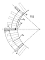
- Figure 2 shows a typical coil for a larger electric motor or generator comprising a loop of generally rectangular shape with two straight, parallel sections 12 that fit- as shown in Figure 3 - into angularly spaced apart stator slots 31, connected by end sections 13.
- the end sections 13 comprise diagonal sections 13a joined in knuckles 14.
- the straight, parallel sections 12 are angled with respect to each other, as best seen in Figure 3, so that they align more or less precisely with radii of the stator to fit into the slots 31. This angling gives a rather complex geometry to the end sections 13 of the coil.
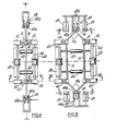
- Figures 4 to 8 illustrate a coil shaper for transforming a loop coil blank as shown in Figure 1 into a diamond coil adapted to fit the stator of a machine as shown in Figures 2 and 3.
- the coil shaper comprises grippers 41 for the corners of the coil and powered means comprising piston-in-cylinder arrangements 42, 43 moving the grippers 41 apart from an initial position as seen in Figures 4 and 5 for insertion of a loop coil blank 40 to a final position as seen Figures 6 and 7 in which the coil is shaped as seen in Figure 2.
- the piston-in-cylinder arrangements 42 are provided one for each gripper 41, and are mounted on rotatable beams 44 mounted on carriages which are separable by the piston-in-cylinder arrangements 43.
- Rotation of the beams 44 rotates the grippers 41 - as best seen by comparing Figures 5 and 7 - so as to angle the slot-fitting sections 12 of the coil about their lengthwise directions. This rotation is effected by further piston-in-cylinder arrangements 46 ( Figures 5 and 7).
- the shaper also comprises endwise disposed grippers 48 for controlling the knuckles 14 of the coil.
- the grippers 48 are adapted to resist inward movement of the knuckles 14 of the coil as the coil is spread. This resistance is effected by piston-in-cylinder arrangements 49 (shown only in Figure 6) attached to anchoring points either side of the long axis of a coil mounted in the shaper and permitting controlled movement of the gripper 48 parallel to and at right angles to said axis - there being two such piston-in-cylinder arrangements at each end of the coil and on opposite sides of the said axis. As illustrated, the piston-in-cylinder arrangements 49 work parallel to the axis, but the pistons may be oppositely inclined towards the said axis.
- the grippers 48 comprise radius pegs 48a and clamps 48b gripping the faces of the coil blank, the clamps 48b being themselves fluid-pressure operated by piston-in-cylinder arrangements, not shown for reason of clarity, both to grip the coil and to control its twisting as the coil is spread.
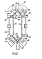
- Figure 8 which is a plan view of the shaper shown in Figure 6 with just a few parts not shown, but with additional features, shows, for each diagonal section 13a of the coil, a further controlling gripper 81 controlled by a further piston-in-cylinder arrangement 82, itself so controlled as to determine the correct angle and position of the section of the diagonal 13a gripped thereby.
- piston-in-cylinder controlled grippers can be added further to control the angles and positions of the diagonal sections at additional points indicated in Figure 8 by lines referenced 83 (also shown in Figure 2).
- each coil will be identical with each other coil.
- the problem is that of providing a coil shaper with a given initial position for all its grippers and a given final position for all its grippers and being able to reproduce these positions. More generally, since the equipment may and probably will be required to produce coils in a range of sizes and a variety of shapes, it involves being able to program the equipment to produce any such desired size and shape of coil. This can be achieved, without need of further explanation, by use of a microprocessor controlling the piston-in-cylinder arrangements via appropriate solenoid valves, servo or stepping motors and/or other means.
- the arrangement of the coil shaper described herein is very well adapted to automatic loading and unloading of coils, since the coil is loaded and unloaded from the top, permitting easy access for mechanical loading/unloading means.
Abstract
Description
- This invention relates to coil shapers for coils for rotating electric machines, more particularly for so-called 'diamond' coils for larger such machines. Such coils comprise loops of conductor, usually copper, having a generally rectangular cross-section that will be a snug fit in a rotor or stator slot. The loops are of a generally rectangular shape with two straight parallel sections, that fit into angularly spaced apart rotor or stator slots, connected by end sections.
- Such coils are made from rectangular cross-section copper strip by winding an elongate loop of several turns of strip so as to form a laminated conductor of generally rectangular cross-section. This loop, which is so narrow that the two parallel straight sections may be touching or practically so, is then pulled out in width on a shaper that brings it to the final shape required to fit the rotor or stator slots. The shaper not only pulls out the straight sections - it also twists the one relatively to the other about its lengthwise axis to fit the angularly separated slots. As a result of this relative twisting, a characteristic "kink" appears in each end of the coil, which then displays a rounded "knuckle".
- A coil shaper comprises a set of four grippers, one for each corner of the coil, initially situated so that the elongate loop can be placed in them. The grippers are pneumatically, hydraulically or otherwise separable and twistable so as to bring the loop into the coil shape required. The shaper is usually adapted to produce different sizes and shapes of coil by adjustment of its parts as required so that once an elongate loop is in position and the "go" button pressed, the operation is automatic.
- On all existing coil shapers, however, certain operations must be effected manually - the only "automatic" part of the operation is the predetermined movement of the grippers.
- The most important manual operation involves the formation of the "kink" above referred to, which is initiated, while the grippers are effecting their predetermined movement to spread the coil, by a mallet blow.
- US-A-2 841 200 describes a typical prior art coil shaper.
- GB-A-2079194 describes an improved coil shaper in which the coil is held inverted as compared to previously known shapers, whereby the mallet blow could be effected more easily and accurately. Though the improvement brought about by this development was substantial, nevertheless, the requirement is still there for manual assistance at all stages of the shaping operation, including the final shaping of the ends of the coil. Not only is this expensive in terms of labour costs, but it also results in coils which are not necessarily accurately shaped and which usually require substantial further shaping to bring them within specification after the coil has been removed from the shaper. Even then, it is usually found that conventionally produced coils are not a good fit in the machine for which they are intended, and, in fitting them, further 'modification' - usually involving hammering and other operations potentially harmful to the insulation which has by now been applied to the coils - is required in winding the machine. The shaper described in GB-A-2 079 194 can produce better coils than previously known shapers because less difficulty is involved at the shaping stage. It can also produce coils in less time, thereby reducing the overall coil cost. It is found to be very suitable for repair shop operations, where relatively short runs of coils are required, because not only is it far more efficient than other shapers, but also its capital cost is moderate.
- GB-A-941643 describes another prior art shaper which is said to overcome the problem of producing precise radii at the bends i.e. the diagonal sections between the straight, slot-fitting sections of the coil and the knuckles of the overhang sections. Such problem is clearly found with the shaper of US―A―2 841 200, which has no measures of any description automatically to shape these diagonal sections, as well as with GB-A-2 079 194.
- The solution adopted in GB-A-941643 is to provide templates around which the diagonal sections are formed. However, this solution still does not accurately shape the diagonal sections because the template only controls the curvature about one axis - the coil section is still free to slide laterally on the template surface. Moreover, for different shapes and sizes of coil, different templates have to be produced, and the geometry is complex not least because the diagonal section twists about its longitudinal axis which, making such templates difficult and costly to produce. For a coil producing operation with a varied output an inventory of templates must be kept, retrieved from store as required and fitted to the shaping machine, which must then be set up most carefully with respect to the position of the templates.
- ' The present invention overcomes the problems associated with GB-A-941643 and the other prior art referred to and enables perfectly shaped, identical coils to be produced to any size and shape without the production of expensive templates and with perfect control of the entire overhang section of the coil.
- The solution is to provide a further gripper for each diagonal section of the coil between the slot-fitting sections and the knuckle, said further grippers being adapted to locate the parts of the said diagonal sections which are to remain unrotated about its lengthwise directions.
- If the rotation of a slot-fitting section about its lengthwise direction is regarded as a positive rotation, then the rotation of the diagonal section near the knuckle will be negative, so that in between there will be a point on the diagonal where the rotation is zero.
- Additional grippers may be provided for each diagonal section either side of said first mentioned third shaping means.
- These grippers can be controlled like the main coil spreading grippers to control the shape of the diagonals and the formation of the knuckles much more accurately and with substantially less damage to the material of the coil than is possible with manual techniques. It is also, by eliminating manual intervention at this stage, possible to increase the rate of operation so that the new machine will produce many more coils per hour than prior art shapers.
- The said grippers may comprise coil-section engaging claw members fixed at the ends of adjustable arms and co-operating clamping members, which latter clamping members may also be be fluid pressure actuated. The adjustable arms may be adjustable both as to length and orientation, and may be adjusted by fluid pressure means.
- Control means may be provided adapted to control the shaper to perform a fixed cycle of operation repetitively, and said control means may be adapted to be programmed to carry out different operational cycles to produce coils to different specifications. The control means may comprise a micro-processor, which may be programmable by inputting information about the initial loop coil blank and the configuration of the finished coil. The initial positions, namely those appropriate to the start of a coil-spreading cycle, may be adjusted manually at the start of a series of cycles, such positions being storable in micro- processor memory so that they can be restored for a new cycle. The input information can then determine the movement of the movable parts of the shaper away from their initial positions.
- The shaper may also comprise loading means automatically loading a loop coil blank on to the grippers and, if desired, unloading means automatically off-loading a finished shaped coil after release of the grippers.
- The construction of the machine, in particular the placement of the further gripper means for controlling the diagonal sections, is facilitated by adopting the measures described in GB-A-2079194 above referred to, namely the inverting of the coil as compared to previously known shapers. As will be seen from GB-A-941643, the centre of curvature of the diagonal sections is below the coil, the templates being therefore located below the coil. With the inverted arrangement according to GB-A-2079194 the centre of curvature is above, enabling the said further grippers to be located above the coil where there is considerably more space than below. This arrangement also facilitates automatic loading and unloading of the coil loop blank and the finished coil from above so that the entire operation of loading, shaping and unloading the coil can be performed accurately and completely automatically without any manual intervention at all which not only makes for coils of improved accuracy of shape but also a less expensive and more rapid production process.
- One embodiment of a coil shaper according to the invention will now be described with reference to the accompanying drawings, in which:
- Figure 1 is a perspective view of an elongate loop coil blank,
- Figure 2 is a perspective view of a shaped coil,
- Figure 3 is an end-on-view of part of a partly wound stator showing one coil in place,
- Figure 4 is a plan view of a shaper according to the invention in its initial position,
- Figure 5 is a section on the line V-V of Figure 4,
- Figure 6 is a plan view of the shaper in Figure 4 after spreading a coil,
- Figure 7 is a section on the line VII-VII of Figure 6, and
- Figure 8 is a plan view of the shaper as shown in Figure 6, with additional features, which are not shown in the other Figures.
- The elongate loop coil blank shown in Figure 1 consists of a simple winding of insulated copper of rectangular cross section, the
ends 11 of the copper terminating at the same end of the coil. The winding consists of about four turns. It is required to bring this blank into the shape shown in Figure 2 in order to fit into the slots of the rotor or stator of an electric machine. Figure 2 shows a typical coil for a larger electric motor or generator comprising a loop of generally rectangular shape with two straight,parallel sections 12 that fit- as shown in Figure 3 - into angularly spaced apartstator slots 31, connected byend sections 13. Theend sections 13 comprisediagonal sections 13a joined inknuckles 14. - The straight,
parallel sections 12 are angled with respect to each other, as best seen in Figure 3, so that they align more or less precisely with radii of the stator to fit into theslots 31. This angling gives a rather complex geometry to theend sections 13 of the coil. - Figures 4 to 8 illustrate a coil shaper for transforming a loop coil blank as shown in Figure 1 into a diamond coil adapted to fit the stator of a machine as shown in Figures 2 and 3.
- The coil shaper comprises
grippers 41 for the corners of the coil and powered means comprising piston-in-cylinder arrangements grippers 41 apart from an initial position as seen in Figures 4 and 5 for insertion of a loop coil blank 40 to a final position as seen Figures 6 and 7 in which the coil is shaped as seen in Figure 2. - The piston-in-
cylinder arrangements 42 are provided one for eachgripper 41, and are mounted onrotatable beams 44 mounted on carriages which are separable by the piston-in-cylinder arrangements 43. - Rotation of the
beams 44 rotates the grippers 41 - as best seen by comparing Figures 5 and 7 - so as to angle the slot-fittingsections 12 of the coil about their lengthwise directions. This rotation is effected by further piston-in-cylinder arrangements 46 (Figures 5 and 7). - The shaper also comprises endwise disposed
grippers 48 for controlling theknuckles 14 of the coil. Thegrippers 48 are adapted to resist inward movement of theknuckles 14 of the coil as the coil is spread. This resistance is effected by piston-in-cylinder arrangements 49 (shown only in Figure 6) attached to anchoring points either side of the long axis of a coil mounted in the shaper and permitting controlled movement of thegripper 48 parallel to and at right angles to said axis - there being two such piston-in-cylinder arrangements at each end of the coil and on opposite sides of the said axis. As illustrated, the piston-in-cylinder arrangements 49 work parallel to the axis, but the pistons may be oppositely inclined towards the said axis. - The
grippers 48 comprise radius pegs 48a and clamps 48b gripping the faces of the coil blank, the clamps 48b being themselves fluid-pressure operated by piston-in-cylinder arrangements, not shown for reason of clarity, both to grip the coil and to control its twisting as the coil is spread. - The arrangement described so far is capable, given suitable controls for the movement of the piston-in-cylinder arrangements, of spreading a loop coil blank into a diamond coil with good control over the spreading and angling of the straight, parallel slot-fitting-
sections 12 and the position and orientation ofthe.knuckles 14. - According to the invention the main improvement in shaping the ends of the coil, however, is obtained by providing further grippers as shown in Figure 8.
- Figure 8, which is a plan view of the shaper shown in Figure 6 with just a few parts not shown, but with additional features, shows, for each
diagonal section 13a of the coil, a further controllinggripper 81 controlled by a further piston-in-cylinder arrangement 82, itself so controlled as to determine the correct angle and position of the section of the diagonal 13a gripped thereby. - Further similar piston-in-cylinder controlled grippers can be added further to control the angles and positions of the diagonal sections at additional points indicated in Figure 8 by lines referenced 83 (also shown in Figure 2).
- When the
grippers 81 and further grippers for thepoints 83 are added, given proper control, of course, of the associated piston-in-cylinder arrangements, the accuracy with which the coil is shaped is considerably further improved. At least, provided the motions of the various grippers are exactly, or substantially exactly, reproduced from coil to coil, each coil will be identical with each other coil. At its simplest, the problem is that of providing a coil shaper with a given initial position for all its grippers and a given final position for all its grippers and being able to reproduce these positions. More generally, since the equipment may and probably will be required to produce coils in a range of sizes and a variety of shapes, it involves being able to program the equipment to produce any such desired size and shape of coil. This can be achieved, without need of further explanation, by use of a microprocessor controlling the piston-in-cylinder arrangements via appropriate solenoid valves, servo or stepping motors and/or other means. - The arrangement of the coil shaper described herein is very well adapted to automatic loading and unloading of coils, since the coil is loaded and unloaded from the top, permitting easy access for mechanical loading/unloading means.
Claims (3)
Priority Applications (1)
| Application Number | Priority Date | Filing Date | Title |
|---|---|---|---|
| AT83305280T ATE26776T1 (en) | 1982-09-09 | 1983-09-09 | DEVICE FOR FORMING COILS OF ELECTRIC LATHES. |
Applications Claiming Priority (2)
| Application Number | Priority Date | Filing Date | Title |
|---|---|---|---|
| GB8225804 | 1982-09-09 | ||
| GB08225804A GB2126505A (en) | 1982-09-09 | 1982-09-09 | Coil shapers for coils of rotating electric machines |
Publications (2)
| Publication Number | Publication Date |
|---|---|
| EP0107314A1 EP0107314A1 (en) | 1984-05-02 |
| EP0107314B1 true EP0107314B1 (en) | 1987-04-22 |
Family
ID=10532822
Family Applications (1)
| Application Number | Title | Priority Date | Filing Date |
|---|---|---|---|
| EP83305280A Expired EP0107314B1 (en) | 1982-09-09 | 1983-09-09 | Coil shapers for coils of rotating electric machines |
Country Status (5)
| Country | Link |
|---|---|
| US (1) | US4964291A (en) |
| EP (1) | EP0107314B1 (en) |
| AT (1) | ATE26776T1 (en) |
| DE (1) | DE3371145D1 (en) |
| GB (1) | GB2126505A (en) |
Families Citing this family (14)
| Publication number | Priority date | Publication date | Assignee | Title |
|---|---|---|---|---|
| FI90930C (en) * | 1985-10-15 | 1994-04-11 | Siemens Ag | Method and apparatus for bending a number of adjacent and / or superposed electrically insulated rod-shaped conductors |
| AU579045B2 (en) * | 1986-01-28 | 1988-11-10 | Mitsubishi Denki Kabushiki Kaisha | Method of manufacturing a diamond coil for a rotating electric machine |
| JPH0687644B2 (en) * | 1986-06-25 | 1994-11-02 | 三菱電機株式会社 | Electric motor coil manufacturing method |
| AU663598B2 (en) * | 1992-06-01 | 1995-10-12 | General Electric Company | Method and apparatus for producing form wound stator coils |
| JPH1066314A (en) * | 1996-08-14 | 1998-03-06 | Toyota Motor Corp | Manufacture of stator of motor |
| FI112412B (en) * | 1997-04-18 | 2003-11-28 | Kone Corp | Process for producing the winding of an electric machine |
| FR2824202B1 (en) * | 2001-04-27 | 2004-06-04 | Vincent Ind | DEVICE FOR FORMING THE DEVELOPANTS OF WINDINGS OF ELECTRIC ROTATING MACHINES |
| JP5675515B2 (en) * | 2011-07-01 | 2015-02-25 | トヨタ自動車株式会社 | Manufacturing method and manufacturing apparatus for concentric winding cassette coil |
| EP2680414B1 (en) * | 2012-06-29 | 2019-12-04 | VENSYS Energy AG | Method for manufacturing a coil for the generator of a wind turbine |
| FR2998495B1 (en) * | 2012-11-28 | 2014-12-26 | Vincent Ind | MACHINE FOR FORMING A COIL AND / OR A METAL BAR |
| CN104518623B (en) * | 2014-12-30 | 2017-01-04 | 中船重工电机科技股份有限公司 | The double circle stator-coil forming apparatus of multiply |
| EP3176924A1 (en) * | 2015-12-02 | 2017-06-07 | Siemens Aktiengesellschaft | Method for manufacturing a form coil |
| US11108307B2 (en) * | 2017-09-29 | 2021-08-31 | Honda Motor Co., Ltd. | Coil for rotary electric machine and insertion method |
| CN114094786B (en) * | 2022-01-21 | 2022-05-10 | 山西汾西重工有限责任公司 | One-time winding forming combined tool for direct current propulsion motor reversing pole coil |
Family Cites Families (19)
| Publication number | Priority date | Publication date | Assignee | Title |
|---|---|---|---|---|
| US1435284A (en) * | 1920-12-23 | 1922-11-14 | Alvin J Fathauer | Coil-forming apparatus |
| US1495959A (en) * | 1922-10-17 | 1924-05-27 | Victor T Mavity | Coil-forming apparatus |
| US1566227A (en) * | 1924-03-26 | 1925-12-15 | Pleasant John William | Coil spreader |
| US2106525A (en) * | 1936-07-23 | 1938-01-25 | J G Brill Co | Universal tool holder |
| US2207881A (en) * | 1938-11-05 | 1940-07-16 | Wesson Company | Universal vise and workholder |
| US2451222A (en) * | 1946-09-05 | 1948-10-12 | Robert B James | Coil former |
| US2506219A (en) * | 1948-09-03 | 1950-05-02 | Robert B James | Slot holder |
| US2841200A (en) * | 1955-02-04 | 1958-07-01 | James Equipment Company Inc | Apparatus for spreading a coil and twisting the sides thereof |
| US2962076A (en) * | 1958-06-20 | 1960-11-29 | James Equipment Company Inc | Coil forming apparatus |
| CH385984A (en) * | 1961-02-23 | 1964-12-31 | Oerlikon Maschf | Device for shaping coils of electrical machines |
| US3145756A (en) * | 1961-09-19 | 1964-08-25 | Baldwin Lima Hamilton Corp | Numerically controlled tube bending machine |
| DD33896B1 (en) * | 1963-08-22 | 1966-07-05 | Device for forming coils of electrical machines | |
| BE666789A (en) * | 1965-07-13 | 1966-01-13 | Acec | Universal machine for deploying winding sections of electric machines |
| US3452786A (en) * | 1966-09-21 | 1969-07-01 | Kurz & Root Co Inc | Apparatus for forming a winding |
| US4145006A (en) * | 1977-11-11 | 1979-03-20 | Webb William E | Work piece mounting stand |
| JPS54156102A (en) * | 1978-05-30 | 1979-12-08 | Matsushita Electric Ind Co Ltd | Method and machine of manufacturing stators of electrical machines |
| US4262891A (en) * | 1979-06-04 | 1981-04-21 | Kinney Charles G | Three dimensional positionable workpiece support table |
| US4317560A (en) * | 1979-12-26 | 1982-03-02 | Troyer Wade E | Work manipulator |
| US4402234A (en) * | 1981-08-13 | 1983-09-06 | General Motors Corporation | Three-axis wrist mechanism |
-
1982
- 1982-09-09 GB GB08225804A patent/GB2126505A/en not_active Withdrawn
-
1983
- 1983-09-09 EP EP83305280A patent/EP0107314B1/en not_active Expired
- 1983-09-09 DE DE8383305280T patent/DE3371145D1/en not_active Expired
- 1983-09-09 AT AT83305280T patent/ATE26776T1/en active
-
1986
- 1986-05-05 US US06/861,648 patent/US4964291A/en not_active Expired - Fee Related
Also Published As
| Publication number | Publication date |
|---|---|
| DE3371145D1 (en) | 1987-05-27 |
| US4964291A (en) | 1990-10-23 |
| ATE26776T1 (en) | 1987-05-15 |
| EP0107314A1 (en) | 1984-05-02 |
| GB2126505A (en) | 1984-03-28 |
Similar Documents
| Publication | Publication Date | Title |
|---|---|---|
| EP0107314B1 (en) | Coil shapers for coils of rotating electric machines | |
| JP6423931B1 (en) | Coil segment forming apparatus, coil segment forming method, and rotating electrical machine manufacturing apparatus | |
| US6295720B1 (en) | Device for producing a coil arrangement | |
| WO2019049432A1 (en) | Rotary electric machine manufacturing device and manufacturing method | |
| EP0469426B2 (en) | Methods and apparatus for connecting stator coil leads | |
| US5413289A (en) | Programmably controlled armature winding apparatus | |
| US5479810A (en) | Method for producing form wound stator coils | |
| US3812577A (en) | Armature winding method and apparatus | |
| US11881748B2 (en) | Method of inserting a hairpin | |
| US4558580A (en) | Coil shaping apparatus | |
| US11509200B2 (en) | Process for making a continuous bar winding for an electric machine | |
| US3431759A (en) | Forming apparatus | |
| FI90930C (en) | Method and apparatus for bending a number of adjacent and / or superposed electrically insulated rod-shaped conductors | |
| JPH06284651A (en) | Manufacture of coil for motor | |
| JPH01234036A (en) | Stator coil former and its manufacture | |
| US3812570A (en) | Apparatus for handling magnetic cores and performing winding procedures | |
| WO2010050253A1 (en) | Toroidal coil manufacturing device | |
| US3580030A (en) | Coil former | |
| US3942246A (en) | Method of making armature windings for commutator type dynamo-electric machines | |
| US4305435A (en) | Winding and cutting device | |
| JPS598141B2 (en) | Electric coil bar forming equipment for rotating electric machines | |
| JP5991275B2 (en) | Wiring component wiring method and wiring device | |
| EP0299554A1 (en) | Method for securing wire coiled onto a spool, apparatus for securing wire coiled onto a spool, as well as spool containing wire coiled thereon | |
| US6036135A (en) | Winding of coils into axial slots in rotationally symmetric bodies of electrical devices | |
| JPS6135108B2 (en) |
Legal Events
| Date | Code | Title | Description |
|---|---|---|---|
| PUAI | Public reference made under article 153(3) epc to a published international application that has entered the european phase |
Free format text: ORIGINAL CODE: 0009012 |
|
| AK | Designated contracting states |
Designated state(s): AT BE CH DE FR GB IT LI LU NL SE |
|
| 17P | Request for examination filed |
Effective date: 19850102 |
|
| 17Q | First examination report despatched |
Effective date: 19860117 |
|
| GRAA | (expected) grant |
Free format text: ORIGINAL CODE: 0009210 |
|
| AK | Designated contracting states |
Kind code of ref document: B1 Designated state(s): AT BE CH DE FR GB IT LI LU NL SE |
|
| PG25 | Lapsed in a contracting state [announced via postgrant information from national office to epo] |
Ref country code: NL Effective date: 19870422 Ref country code: BE Effective date: 19870422 Ref country code: AT Effective date: 19870422 |
|
| REF | Corresponds to: |
Ref document number: 26776 Country of ref document: AT Date of ref document: 19870515 Kind code of ref document: T |
|
| ITF | It: translation for a ep patent filed |
Owner name: JACOBACCI & PERANI S.P.A. |
|
| PG25 | Lapsed in a contracting state [announced via postgrant information from national office to epo] |
Ref country code: SE Effective date: 19870430 |
|
| ET | Fr: translation filed | ||
| REF | Corresponds to: |
Ref document number: 3371145 Country of ref document: DE Date of ref document: 19870527 |
|
| NLV1 | Nl: lapsed or annulled due to failure to fulfill the requirements of art. 29p and 29m of the patents act | ||
| PG25 | Lapsed in a contracting state [announced via postgrant information from national office to epo] |
Ref country code: LU Free format text: LAPSE BECAUSE OF NON-PAYMENT OF DUE FEES Effective date: 19870930 |
|
| PLBE | No opposition filed within time limit |
Free format text: ORIGINAL CODE: 0009261 |
|
| STAA | Information on the status of an ep patent application or granted ep patent |
Free format text: STATUS: NO OPPOSITION FILED WITHIN TIME LIMIT |
|
| 26N | No opposition filed | ||
| PGFP | Annual fee paid to national office [announced via postgrant information from national office to epo] |
Ref country code: GB Payment date: 19920309 Year of fee payment: 9 |
|
| PGFP | Annual fee paid to national office [announced via postgrant information from national office to epo] |
Ref country code: CH Payment date: 19920311 Year of fee payment: 9 |
|
| PGFP | Annual fee paid to national office [announced via postgrant information from national office to epo] |
Ref country code: FR Payment date: 19920316 Year of fee payment: 9 |
|
| PGFP | Annual fee paid to national office [announced via postgrant information from national office to epo] |
Ref country code: DE Payment date: 19920326 Year of fee payment: 9 |
|
| PG25 | Lapsed in a contracting state [announced via postgrant information from national office to epo] |
Ref country code: GB Effective date: 19920909 |
|
| ITTA | It: last paid annual fee | ||
| PG25 | Lapsed in a contracting state [announced via postgrant information from national office to epo] |
Ref country code: LI Effective date: 19920930 Ref country code: CH Effective date: 19920930 |
|
| GBPC | Gb: european patent ceased through non-payment of renewal fee |
Effective date: 19920909 |
|
| PG25 | Lapsed in a contracting state [announced via postgrant information from national office to epo] |
Ref country code: FR Effective date: 19930528 |
|
| REG | Reference to a national code |
Ref country code: CH Ref legal event code: PL |
|
| PG25 | Lapsed in a contracting state [announced via postgrant information from national office to epo] |
Ref country code: DE Effective date: 19930602 |
|
| REG | Reference to a national code |
Ref country code: FR Ref legal event code: ST |