EP0102625A2 - Ausklinkvorrichtung - Google Patents
Ausklinkvorrichtung Download PDFInfo
- Publication number
- EP0102625A2 EP0102625A2 EP83108645A EP83108645A EP0102625A2 EP 0102625 A2 EP0102625 A2 EP 0102625A2 EP 83108645 A EP83108645 A EP 83108645A EP 83108645 A EP83108645 A EP 83108645A EP 0102625 A2 EP0102625 A2 EP 0102625A2
- Authority
- EP
- European Patent Office
- Prior art keywords
- adjusting ring
- axis
- rotation
- notching device
- notching
- Prior art date
- Legal status (The legal status is an assumption and is not a legal conclusion. Google has not performed a legal analysis and makes no representation as to the accuracy of the status listed.)
- Granted
Links
Images
Classifications
-
- B—PERFORMING OPERATIONS; TRANSPORTING
- B23—MACHINE TOOLS; METAL-WORKING NOT OTHERWISE PROVIDED FOR
- B23D—PLANING; SLOTTING; SHEARING; BROACHING; SAWING; FILING; SCRAPING; LIKE OPERATIONS FOR WORKING METAL BY REMOVING MATERIAL, NOT OTHERWISE PROVIDED FOR
- B23D15/00—Shearing machines or shearing devices cutting by blades which move parallel to themselves
- B23D15/002—Shearing machines or shearing devices cutting by blades which move parallel to themselves for cutting in more than one direction, e.g. angle cutting
-
- Y—GENERAL TAGGING OF NEW TECHNOLOGICAL DEVELOPMENTS; GENERAL TAGGING OF CROSS-SECTIONAL TECHNOLOGIES SPANNING OVER SEVERAL SECTIONS OF THE IPC; TECHNICAL SUBJECTS COVERED BY FORMER USPC CROSS-REFERENCE ART COLLECTIONS [XRACs] AND DIGESTS
- Y10—TECHNICAL SUBJECTS COVERED BY FORMER USPC
- Y10S—TECHNICAL SUBJECTS COVERED BY FORMER USPC CROSS-REFERENCE ART COLLECTIONS [XRACs] AND DIGESTS
- Y10S83/00—Cutting
- Y10S83/917—Notching
-
- Y—GENERAL TAGGING OF NEW TECHNOLOGICAL DEVELOPMENTS; GENERAL TAGGING OF CROSS-SECTIONAL TECHNOLOGIES SPANNING OVER SEVERAL SECTIONS OF THE IPC; TECHNICAL SUBJECTS COVERED BY FORMER USPC CROSS-REFERENCE ART COLLECTIONS [XRACs] AND DIGESTS
- Y10—TECHNICAL SUBJECTS COVERED BY FORMER USPC
- Y10T—TECHNICAL SUBJECTS COVERED BY FORMER US CLASSIFICATION
- Y10T83/00—Cutting
- Y10T83/869—Means to drive or to guide tool
- Y10T83/8737—With tool positioning means synchronized with cutting stroke
-
- Y—GENERAL TAGGING OF NEW TECHNOLOGICAL DEVELOPMENTS; GENERAL TAGGING OF CROSS-SECTIONAL TECHNOLOGIES SPANNING OVER SEVERAL SECTIONS OF THE IPC; TECHNICAL SUBJECTS COVERED BY FORMER USPC CROSS-REFERENCE ART COLLECTIONS [XRACs] AND DIGESTS
- Y10—TECHNICAL SUBJECTS COVERED BY FORMER USPC
- Y10T—TECHNICAL SUBJECTS COVERED BY FORMER US CLASSIFICATION
- Y10T83/00—Cutting
- Y10T83/869—Means to drive or to guide tool
- Y10T83/8742—Tool pair positionable as a unit
-
- Y—GENERAL TAGGING OF NEW TECHNOLOGICAL DEVELOPMENTS; GENERAL TAGGING OF CROSS-SECTIONAL TECHNOLOGIES SPANNING OVER SEVERAL SECTIONS OF THE IPC; TECHNICAL SUBJECTS COVERED BY FORMER USPC CROSS-REFERENCE ART COLLECTIONS [XRACs] AND DIGESTS
- Y10—TECHNICAL SUBJECTS COVERED BY FORMER USPC
- Y10T—TECHNICAL SUBJECTS COVERED BY FORMER US CLASSIFICATION
- Y10T83/00—Cutting
- Y10T83/869—Means to drive or to guide tool
- Y10T83/8821—With simple rectilinear reciprocating motion only
- Y10T83/8828—Plural tools with same drive means
- Y10T83/8831—Plural distinct cutting edges on same support
-
- Y—GENERAL TAGGING OF NEW TECHNOLOGICAL DEVELOPMENTS; GENERAL TAGGING OF CROSS-SECTIONAL TECHNOLOGIES SPANNING OVER SEVERAL SECTIONS OF THE IPC; TECHNICAL SUBJECTS COVERED BY FORMER USPC CROSS-REFERENCE ART COLLECTIONS [XRACs] AND DIGESTS
- Y10—TECHNICAL SUBJECTS COVERED BY FORMER USPC
- Y10T—TECHNICAL SUBJECTS COVERED BY FORMER US CLASSIFICATION
- Y10T83/00—Cutting
- Y10T83/929—Tool or tool with support
- Y10T83/9411—Cutting couple type
- Y10T83/9442—Notching tool
- Y10T83/9444—Shear type
Definitions
- the invention relates to a notching device of the type specified by claim 1.
- the upper knife as a narrow cutting edge for direct attachment to the head of the vertically movable plunger and the lower knife as a two-part or multi-part knife set for attachment by means of a die a die holder of the machine table.
- a workpiece guide formed from a base plate and a support plate is arranged with stop plates adjustably attached to the support plate for a workpiece to be released, the support plate having an angular cutout of 90 ° formed in the displacement path of the upper knife and on the base plate around the notch tip Axis of rotation is pivotable.
- This known notching device makes it possible, by means of two successive working strokes of the ram and a pivoting of the workpiece guide carried out in between, from a first rest position set by means of stops according to a desired angle to a likewise set second rest position, angles of any size up to a maximum of 90 ° notching out of workpieces, whereby for each of the two working strokes, optimal cutting conditions between the cutting edge of the upper knife and the two cutting edges of the lower knife, which take effect alternately, are ensured.
- the invention solves the problem of designing a notching device of the type specified so that the notches to be carried out on a workpiece, even larger dimensions, for any size of the angle with two working strokes can be carried out more safely for the operator and there is a simple possibility of adjusting the device when changing to another desired angle.
- the advantages achieved by the invention are essentially that the provision of the jointly pivotable adjusting rings as a holder for the notching knife and the simultaneous formation of the lower adjusting ring as an auxiliary table does not change the relative position of the workpiece between the two working strokes with respect to the machine table, since at the pivoting of the collars from a corre sponding According to the desired angle set first rest position in a set second rest position, the lower adjusting ring with the lower knife attached to it can be moved past the workpiece preferably arranged between table stops.
- the notching device according to the invention can be provided, for example, on a notching machine of the design described in US Pat. No. 4,129,054, by using a rearward arm 1 above a rearward arm on the vertically movable plunger gene machine table 2 is formed. It is then alternatively possible, with the upper knife provided on the front arm of the ram and the lower knife provided on the front machine table, to release constant angles of, for example, 90 °, while the rear of the notching machine for releasing variable angles between, for example, 30 ° and 120 ° reserved.
- the notching device comprises an upper knife 3 formed in one piece with a point angle of 30 ° between its two cutting edges and a lower knife 4 composed of two individual knives at the same point angle.
- the cutting tips of these two notching knives can be provided with a curve with a radius of curvature of 0.5 mm .
- the upper knife 3 is fixed to an upper adjusting ring 5 by means of bolts 6.
- the upper adjusting ring 5 is fixed in a center of rotation of the upper knife tip axis of rotation 7 by means of a pivot 8 and a nut 9 screwed thereon on the rear arm 1 of the plunger.
- a first guide groove 10 is formed on the upper adjusting ring 5 and has a circular curvature concentric with the axis of rotation 7.
- a projection 11 of a first sliding piece 12 surrounds, which is fixed by means of screws 13 on the rear arm 1 of the plunger and also has a circular curvature course which is concentric with the axis of rotation 7.
- the guide groove 10 and the slider 12 result in a guide length corresponding to a central angle of 150 ° for the upper adjusting ring 5.
- On the upper adjusting ring 5 there is also a guide pin in a rigid axis 14 parallel to the axis of rotation 7 15 formed, which fits into a guide bushing 16 of a lower adjusting ring 17 provided for fastening the lower knife 4.
- the two individual knives 18 and 19 of the lower knife 4 are arranged within a cutout 21 of this lower adjusting ring 17, this cutout 21 being connected to an opening 22 through which the sheet metal waste obtained can be removed.
- the lower adjusting ring 17 has a pivot pin 23 which runs in the axis of rotation 7 and which engages in a bearing bore of a fastening piece 25 fastened to the rear machine table 2 by means of bolts 24.
- the support of the lower adjusting ring 17 with respect to the rear machine table 2 obtained by means of the fastening piece 25 in the area of the axis of rotation 7 is supplemented in the area of the rigid axle 14 by a second slide piece 26, which is likewise fixed to the machine table 2 by means of bolts 27 and like the first one Slider 12 has a circular curvature concentric to the axis of rotation 7 with a guide length corresponding to a central angle of 150 °.
- the second slider 26 also has a projection 28 with which it fits into a second guide groove 29 of the lower adjusting ring 17.
- the adjusting rings 5 and 17 connected to one another via the rigid axis 14 can thus be pivoted together about the axis of rotation 7.
- the lower adjusting ring 17 is designed as an auxiliary table arranged parallel to the rear machine table 2, which is inserted in an opening 30 of a stop table 31 arranged plane-parallel with this auxiliary table.
- the stop table 31 is supported on the machine table 2 by four support columns 32 and by means of bolts 33 attached.
- T-slots (not shown in more detail) for adjustable table stops for the workpieces are formed in the stop table 31 and are held in place for the release by means of hold-down devices, also not shown.
- the lower adjusting ring 17 can be ascertained on the stop table 31 by means of a toggle handle arrangement 34 which comprises a circular guide segment 35 which is concentric with the axis of rotation 7 and also has a guide length corresponding to a central angle of 150 °.
- an actuator in the form of a double-acting pressure cylinder 36 for the joint adjustment of the two adjusting rings 5 and 17 is also attached to the stop table 31, the piston rod 37 of this pressure cylinder being articulated on the lower adjusting ring 17.
- an NC-controlled spindle drive can also be provided as the actuator.
- the two adjusting rings 5 and 17 are also provided with an angle scale 38 which extends over 150 ° and in which two zero marks are provided which are oriented on the axis of rotation 7 with a central angle of 30 ° and with respect to which two halves of this angle scale each extend by 60 °.
- workpieces 39 can be placed on the auxiliary table formed by the lower adjusting ring 17 and the stop table 31. Notches are generated with the minimum tip angle of 30 ° specified for the two notching knives.
- the ver adjustable table stops of the stop table 31 created workpieces 39 are first provided in a first relative swivel position I of the upper knife 3 and thus a corresponding swivel position of the lower knife 4 with a first working stroke of the ram at an angle of 30 °.
- the two notching knives have to be adjusted by rotating the two adjusting rings 5 and 17 together about the axis of rotation 7 by means of the pressure cylinder 36 into a second swivel position II, whereupon the angle is adjusted to the desired finished dimension of 60 ° or 67 with a second working stroke of the ram , 5 ° is expanded.
- the determination of the second pivot position II is carried out by actuating the K lever handle arrangement 34, with which the lower adjusting ring 17 is detached from the stop table 31 and thus together with the upper adjusting ring 5 can be pivoted about the axis of rotation 7 along the angle scale 38, on which the Difference in angle to the larger angle can be read exactly, and it is thus also possible to set the second pivot position II precisely with a renewed actuation of the toggle grip arrangement 34.
- the pivoting of the two adjusting rings when the toggle grip arrangement is released can be done with or without the support of the pressure cylinder 36.
- the two set once pivoting positions I and II can be fixed by means of adjustable stops in the other, which then in conjunction with a suitable coupling of the B e-actuation of the pressure cylinder 36 provides the possibility of the working strokes of the plunger, that the two adjusting rings 5 and 17 for a successive machining of workpieces with two working strokes of the ram between these working strokes are automatically adjusted from the swivel position I to the swivel position II.
- the upper knife 3 can be composed of two individually replaceable individual knives.
- Both notching knives can also consist, for example, of three individual knives arranged in a triangle, with which it is then also possible by means of the notching device to produce correspondingly polygonal punchings in workpieces with at least two working strokes of the ram.
Abstract
Description
- Die Erfindung bezieht sich auf eine Ausklinkvorrichtung der durch den Patentanspruch 1 angegebenen Gattung.
- Bei einer aus der DE-OS'29 31 410 bekannten Ausklinkvorrichtung dieser Art sind das Obermesser als eine schmale Schneide für eine unmittelbare Befestigung an dem Kopf des vertikal beweglichen Stößels und das Untermesser als ein zwei- oder mehrteiliger Messersatz für eine Befestigung mittels einer Matrize an einem Matrizenhalter des Maschinentisches ausgebildet. Oberhalb dieses Matrizenhalters ist eine aus einer Grundplatte und einer Auflageplatte gebildete Werkstückführung mit an der Auflageplatte verstellbar befestigten Anschlagplatten für ein auszuklinkendes Werkstück angeordnet, wobei die Auflageplatte einen im Verschiebeweg des Obermessers ausgebildeten Winkelausschnitt von 90° aufweist und auf der Grundplatte um die nahe der Ausklinkspitze liegende Drehachse verschwenkbar ist. Damit ist es mittels dieser bekannten Ausklinkvorrichtung möglich, mittels zweier aufeinanderfolgender Arbeitshübe des Stößels und einer dazwischen vorgenommenen Verschwenkung der Werkstückführung aus einer mittels Anschlägen entsprechend einem gewünschten Winkel eingestellten ersten Ruhelage in eine ebenfalls eingestellte zweite Ruhelage beliebig große Winkel bis maximal 90° aus Werkstücken auszuklinken, wobei für jeden der beiden Arbeitshübe optimale Schnittverhältnisse zwischen der Schneide des Obermessers und den beiden dabei abwechselnd zur Wirkung kommenden Schneiden des Untermessers sichergestellt sind. Bei dieser bekannten Ausklinkvorrichtung ist jedoch nachteilig, daß bei dieser Aufeinanderfolge der beiden Arbeitshübe des Stößels das auf der Auflageplatte aufliegende Werkstück gemeinsam mit der Werkstückführung verschwenkt wird, so daß insbesondere bei größeren und dabei regelmäßig über den Maschinentisch nach vorne vorstehenden Werkstücken eine ständige Verletzungsgefahr für die vor der Ausklinkvorrichtung stehende Bedienungsperson besteht. Bei größeren Winkeln und einer größeren Schwungmasse der Werkstücke werden auch die für die-beiden Ruhelagen der Werkstückführung verstellbar vorgesehenen Anschläge entsprechend verstärkt beansprucht, so daß die Ausklinkungen ungenau werden können, wenn die Anschläge nicht rechtzeitig nachgestellt werden.
- Die Erfindung, wie sie in den Patentansprüchen gekennzeichnet ist, löst die Aufgabe, eine Ausklinkvorrichtung der angegebenen Gattung so auszubilden, daß die an einem Werkstück auch größerer Abmessung für eine beliebige Größe des Winkels mit zwei Arbeitshüben durchzuführenden Ausklinkungen gefahrloser für die Bedienungsperson vorgenommen werden können und eine einfache Verstellmöglichkeit der Vorrichtung bei einem überwechseln auf einen anderen gewünschten Winkel besteht.
- Die durch die Erfindung erreichten Vorteile liegen im wesentlichen darin, daß durch das Vorsehen der gemeinsam verschwenkbaren Stellringe als Halter für die Ausklinkmesser und die dabei gleichzeitige Ausbildung des unteren Stellringes als Hilfstisch das Werkstück zwischen den beiden Arbeitshüben seine Relativlage bezüglich des Maschinentisches nicht verändert, da bei der Verschwenkung der Stellringe aus einer entsprechend dem jeweils gewünschten Winkel eingestellten ersten Ruhelage in eine eingestellte zweite Ruhelage der untere Stellring mit dem an ihm befestigten Untermesser an dem vorzugsweise zwischen Tischanschlägen angeordneten Werkstück vorbeibewegt werden kann. Da der gemeinsame Schwenkweg dieser Stellringe einfach verändert werden kann, ist damit auch ein problemloses Überwechseln zwischen beliebig großen Winkeln sichergestellt, und es besteht damit auch die Möglichkeit, die beiden Obermesser beispielsweise aus jeweils zwei Einzelmessern mit einem übereinstimmenden Spitzenwinkel von 30° zusammenzusetzen, um so mit nur einem Arbeitshub des Stößels einen Winkel von 30° und mit zwei Arbeitshüben beliebig große Winkel bis 120° und mehr aus Werkstücken ausklinken zu können.
- Ein Ausführungsbeispiel der erfindungsgemäßen Ausklinkvorrichtung ist in der Zeichnung schematisch dargestellt und wird nachfolgend näher beschrieben. Es zeigt
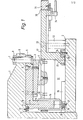
- Figur 1 eine Schnittdarstellung der Ausklinkvorrichtung,
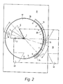
- Figur 2 eine Draufsicht auf das Obermesser und
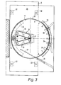
- Figur 3 eine Draufsicht auf das Untermesser der Ausklinkvorrichtung gemäß Figur 1.
- Die erfindungemäße Ausklinkvorrichtung kann beispielsweise an einer Ausklinkmaschine der in der US-PS 4 129 054 beschriebenen Ausbildung vorgesehen werden, indem dafür dann an dem vertikal beweglichen Stößel noch ein rückwärtiger Arm 1 oberhalb eines rückwärtigen Maschinentisches 2 ausgebildet wird. Damit ist es dann alternativ möglich, mit dem an dem vorderen Arm des Stößels vorgesehenen Obermesser und dem an dem vorderen Maschinentisch vorgesehenen Untermesser unveränderliche Winkel von beispielsweise 90° auszuklinken, während die Rückseite der Ausklinkmaschine für das Ausklinken von veränderlichen Winkeln zwischen beispielsweise 30° und 120° vorbehalten bleibt.
- Die Ausklinkvorrichtung umfaßt ein mit einem Spitzenwinkel von 30° zwischen seinen beiden Schneiden einteilig ausgebildetes Obermesser 3 und ein aus zwei Einzelmessern unter dem gleichen Spitzenwinkel zusammengesetztes Untermesser 4. Die Schneidspitzen dieser beiden Ausklinkmesser können mit einer Rundung mit einem Krümmungsradius von 0,5 mm versehen sein. Das Obermesser 3 ist an einem oberen Stellring 5 mittels Bolzen 6 festgelegt. Der obere Stellring 5 ist in einer im Mittelpunkt des Abrundungskreises der Obermesserspitze liegenden Drehachse 7 mittels eines Drehzapfens 8 und einer auf diesen aufgeschraubten Mutter 9 an dem rückwärtigen Arm 1 des Stößels verschwenkbar festgelegt.
- An dem oberen Stellring 5 ist eine erste Führungsnut 10 ausgebildet, die eine zu der Drehachse 7 konzentrische, kreisförmige Krümmung aufweist. In die Führungsnut 10 faßt ein Vorsprung 11 eines ersten Gleitstückes 12 ein, das mittels Schrauben 13 an dem rückwärtigen Arm 1 des Stößels festgelegt ist und ebenfalls einen zu der Drehachse 7 konzentrischen, kreisförmigen Krümmungsverlauf aufweist. Die Führungsnut 10 und das Gleitstück 12 ergeben für den oberen Stellring 5 eine einem Mittelpunktswinkel von 150° entsprechende Führungslänge. An dem oberen Stellring 5 ist weiterhin in einer zur Drehachse 7 parallelen Starrachse 14 ein Führungsbolzen 15 ausgebildet, der in eine Führungsbuchse 16 eines zur Befestigung des Untermessers 4 vorgesehenen unteren Stellringes 17 einfaßt. Die beiden Einzelmesser 18 und 19 des Untermessers 4 sind dabei innerhalb einer Aussparung 21 dieses unteren Stellringes 17 angeordnet, wobei diese Aussparung 21 mit einer öffnung 22 in Verbindung steht, über welche die anfallenden Blechabfälle entnommen werden können.
- Der untere Stellring 17 weist einen in der Drehachse 7 verlaufenden Drehzapfen 23 auf, der in eine Lagerbohrung eines an dem rückwärtigen Maschinentisch 2 mittels Bolzen 24 befestigten Befestigungsstückes 25 einfaßt. Die mittels des Befestigungsstückes 25 im Bereich der Drehachse 7 erhaltene Abstützung-des unteren Stellringes 17 gegenüber dem rückwärtigen Maschinentisch 2 wird im Bereich der Starrachse 14 durch ein zweites Gleitstück 26 ergänzt, das mittels Bolzen 27 ebenfalls an dem Maschinentisch 2 festgelegt ist und wie das erste Gleitstück 12 eine zu der Drehachse 7 konzentrische, kreisförmige Krümmung mit einer einem Mittelpunktswinkel von 150° entsprechenden Führungslänge aufweist. Auch das zweite Gleitstück 26 weist einen Vorsprung 28 auf, mit dem es in eine zweite Führungsnut 29 des unteren Stellringes 17 einfaßt. Die über die Starrachse 14 miteinander verbundenen Stellringe 5 und 17 sind damit um die Drehachse 7 gemeinsam verschwenkbar.
- Der untere Stellring 17 ist als ein zu dem rückwärtigen Maschinentisch 2 parallel angeordneter Hilfstisch ausgebildet, der in einer öffnung 30 eines mit diesem Hilfstisch planparallel angeordneten Anschlagtisches 31 eingesetzt ist. Der Anschlagtisch 31 ist durch vier Abstützsäulen 32 an dem Maschinentisch 2 abgestützt und mittels Bolzen 33 befestigt. In dem Anschlagtisch 31 sind nicht näher gezeigte T-Nuten für verstellbare Tischanschläge für die Werkstücke ausgebildet, die für das Ausklinken mittels ebenfalls nicht näher dargestellter Niederhalter festgehalten werden. Der untere Stellring 17 ist an dem Anschlagtisch 31 mittels einer Knebelgriffanordnung 34 feststellbar, die ein zu der Drehachse 7 konzentrisches, kreisförmiges Führungssegment 35 mit einer ebenfalls einem Mittelpunktswinkel von 150° entsprechenden Führungslänge umfaßt. Weiterhin ist an dem Anschlagtisch 31 noch ein Stellantrieb in der Ausbildung eines doppeltwirkenden Druckzylinders 36 für die gemeinsame Verstellung der beiden Stellringe 5 und 17 befestigt, wobei die Kolbenstange 37 dieses Druckzylinders an dem unteren Stellring 17 angelenkt ist. Anstelle eines solchen doppeltwirkenden Druckzylinders kann als Stellantrieb auch ein NC-gesteuerter Spindelantrieb vorgesehen sein. Die beiden Stellringe 5 und 17 sind schließlich noch mit einer über 150° reichenden Winkelskala 38 versehen, bei der zwei auf die Drehachse 7 mit einem Mittelpunktswinkel von 30° ausgerichtete Nullmarken vorgesehen sind, bezüglich welcher sich zwei Hälften dieser Winkelskala um jeweils 60° erstrecken.
- Wenn die beiden Einzelmesser 18 und 19 des Untermessers 5 und damit auch das Obermesser 4 in die in Figur 3 dargestellte Schwenklage eingestellt sind, dann können damit an Werkstücken 39, die auf den durch den unteren Stellring 17 gebildeten Hilfstisch und den Anschlagtisch 31 aufgelegt werden, Ausklinkungen mit dem für die beiden Ausklinkmesser festliegenden minimalen Spitzenwinkel von 30° erzeugt werden. Wenn an den Werkstücken Ausklinkungen mit einem größeren Winkel bis maximal 120° erzeugt werden sollen, so beispielsweise Ausklinkungen 40 mit einem Winkel von 60° oder 67,5°, so müssen dafür die an die verstellbaren Tischanschläge des Anschlagtisches 31 angelegten Werkstücke 39 zunächst in einer ersten relativen Schwenklage I des Obermessers 3 und einer damit 'entsprechenden Schwenklage auch des Untermessers 4 mit einem ersten Arbeitshub des Stößels mit einem Winkel von 30° versehen werden. Danach müssen die beiden Ausklinkmesser durch ein gemeinsames Verschwenken der beiden Stellringe 5 und 17 um die Drehachse 7 mittels des Druckzylinders 36 in eine zweite Schwenklage II verstellt werden, worauf dann mit einem zweiten Arbeitshub des Stößels der Winkel auf das gewünschte Fertigmaß von 60° oder 67,5° erweitert wird. Die Festlegung der zweiten Schwenklage II wird dabei durch Betätigung der Knebelgriffanordnung 34 vorgenommen, womit der untere Stellring 17 von dem Anschlagtisch 31 gelöst und somit gemeinsam mit dem oberen Stellring 5 um die Drehachse 7 längs der Winkelskala 38 verschwenkt werden kann, auf der somit der Winkelunterschied zu dem größeren Winkel genau abgelesen werden kann und es damit auch möglich ist, die zweite Schwenklage II mit einer erneuten Betätigung der Knebelgriffanordnung 34 präzise einzustellen. Die Verschwenkung der beiden Stellringe bei gelöster Knebelgriffanordnung kann dabei mit oder ohne Unterstützung des Druckzylinders 36 geschehen. Die beiden einmal eingestellten Schwenklagen I und II können im übrigen mittels verstellbarer Anschläge fixiert werden, was dann in Verbindung mit einer geeigneten Ankoppelung der Be-tätigung des Druckzylinders 36 an die Arbeitshübe des Stößels die Möglichkeit schafft, daß die beiden Stellringe 5 und 17 für eine aufeinanderfolgende Bearbeitung von Werkstücken mit jeweils zwei Arbeitshüben des Stößels zwischen diesen Arbeitshüben automatisch aus der Schwenklage I in die Schwenklage II verstellt werden.
- Das Obermesser 3 kann wie das Untermesser 4 aus zwei einzeln auswechselbaren Einzelmessern zusammengesetzt werden. Beide Ausklinkmesser können auch beispielsweise aus drei dreieckförmig angeordneten Einzelmessern bestehen, womit es dann mittels der Ausklinkvorrichtung auch möglich ist, in Werkstükken entsprechend polygonale Ausstanzungen mit wenigstens zwei Arbeitshüben des Stößels zu erzeugen.
Claims (13)
Priority Applications (1)
| Application Number | Priority Date | Filing Date | Title |
|---|---|---|---|
| AT83108645T ATE27416T1 (de) | 1982-09-07 | 1983-09-01 | Ausklinkvorrichtung. |
Applications Claiming Priority (2)
| Application Number | Priority Date | Filing Date | Title |
|---|---|---|---|
| DE3233208A DE3233208C1 (de) | 1982-09-07 | 1982-09-07 | Ausklinkvorrichtung |
| DE3233208 | 1982-09-07 |
Publications (3)
| Publication Number | Publication Date |
|---|---|
| EP0102625A2 true EP0102625A2 (de) | 1984-03-14 |
| EP0102625A3 EP0102625A3 (en) | 1984-05-23 |
| EP0102625B1 EP0102625B1 (de) | 1987-05-27 |
Family
ID=6172644
Family Applications (1)
| Application Number | Title | Priority Date | Filing Date |
|---|---|---|---|
| EP83108645A Expired EP0102625B1 (de) | 1982-09-07 | 1983-09-01 | Ausklinkvorrichtung |
Country Status (5)
| Country | Link |
|---|---|
| US (1) | US4535665A (de) |
| EP (1) | EP0102625B1 (de) |
| JP (1) | JPS5988213A (de) |
| AT (1) | ATE27416T1 (de) |
| DE (2) | DE3233208C1 (de) |
Cited By (2)
| Publication number | Priority date | Publication date | Assignee | Title |
|---|---|---|---|---|
| EP0329259A1 (de) * | 1988-02-18 | 1989-08-23 | Walker-Hagou B.V. | Ausklinkvorrichtung |
| US6978764B1 (en) | 1999-10-18 | 2005-12-27 | Ford Global Technologies, Inc. | Control method for a vehicle having an engine |
Families Citing this family (9)
| Publication number | Priority date | Publication date | Assignee | Title |
|---|---|---|---|---|
| SE465360B (sv) * | 1984-05-02 | 1991-09-02 | Amada Co Ltd | Skaermaskin |
| DE3604516C2 (de) * | 1986-02-13 | 1993-09-30 | Boschert Ludwig Masch | Ausklinkvorrichtung |
| AT387172B (de) * | 1986-12-01 | 1988-12-12 | Haemmerle Ag | Winkelschere |
| IT1214004B (it) * | 1987-10-13 | 1990-01-05 | Eugenio Lenzotti | Macchina punzonatrice e tranciatrice con angolo di taglio variabile |
| DE3835775C1 (de) * | 1988-10-20 | 1990-03-29 | Ludwig Boschert Maschinen- Und Apparatebau Gmbh & Co Kg, 7850 Loerrach, De | |
| DE3838197A1 (de) * | 1988-11-08 | 1990-05-10 | Muhr & Bender | Werkzeugmaschine |
| US5113733A (en) * | 1989-05-02 | 1992-05-19 | Link, Inc. | Adjustable angular shearing device |
| US5881591A (en) * | 1996-08-13 | 1999-03-16 | Ondracek; Carl | Automatic channel letter bending machine |
| JP3452533B2 (ja) * | 2000-05-11 | 2003-09-29 | ファナック株式会社 | 目的形状部切離し装置、該装置を搭載したロボット及び切離し方法 |
Citations (4)
| Publication number | Priority date | Publication date | Assignee | Title |
|---|---|---|---|---|
| DE7225345U (de) * | 1974-07-18 | Maschinenfabrik Weingarten Ag | Schneidvorrichtung für eine Presse zum Ausschneiden von Platinen aus einem durch das Werkzeug intermittierend hindurchgeführten streifen- oder bandförmigen Werkstoff, wie Blechband etc | |
| DE2710855A1 (de) * | 1976-03-15 | 1977-09-22 | Amada Co Ltd | Vorrichtung zum ausstanzen von werkstueckrohlingen |
| DE2601858B2 (de) * | 1976-01-20 | 1977-12-01 | Ludwig Boschert Maschinen- und Apparatebau GmbH & Co KG, 7850 Lörrach | Stanzmaschine |
| DE2931410A1 (de) * | 1979-08-02 | 1981-04-30 | Peddinghaus, Rolf, 5828 Ennepetal | Ausklinkvorrichtung |
Family Cites Families (6)
| Publication number | Priority date | Publication date | Assignee | Title |
|---|---|---|---|---|
| US2555069A (en) * | 1945-12-20 | 1951-05-29 | Verney Jean Louis Francois | Machine for cutting tubes and the like |
| DE2165224C3 (de) * | 1971-12-29 | 1974-07-18 | Iwk-Pressen Gmbh, 3503 Lohfelden | Stanzvorrichtung zur Anwendung in einer Stufenpresse |
| SE398836B (sv) * | 1974-10-16 | 1978-01-23 | Nordisk Kartro Ab | Maskin for kapning av trevirke |
| US3996829A (en) * | 1976-02-23 | 1976-12-14 | Gianfranco Tromponi | Angular shearing machine for laminates, such as sheet metal |
| US4327618A (en) * | 1977-01-31 | 1982-05-04 | Harvey Menard | Apparatus for cutting a strip of material |
| DE8200527U1 (de) * | 1982-01-13 | 1982-07-01 | F.I.M. S.r.l., 40127 Bologna | Eckenschere |
-
1982
- 1982-09-07 DE DE3233208A patent/DE3233208C1/de not_active Expired
-
1983
- 1983-09-01 AT AT83108645T patent/ATE27416T1/de not_active IP Right Cessation
- 1983-09-01 DE DE8383108645T patent/DE3371750D1/de not_active Expired
- 1983-09-01 EP EP83108645A patent/EP0102625B1/de not_active Expired
- 1983-09-06 US US06/529,551 patent/US4535665A/en not_active Expired - Fee Related
- 1983-09-07 JP JP58165826A patent/JPS5988213A/ja active Pending
Patent Citations (4)
| Publication number | Priority date | Publication date | Assignee | Title |
|---|---|---|---|---|
| DE7225345U (de) * | 1974-07-18 | Maschinenfabrik Weingarten Ag | Schneidvorrichtung für eine Presse zum Ausschneiden von Platinen aus einem durch das Werkzeug intermittierend hindurchgeführten streifen- oder bandförmigen Werkstoff, wie Blechband etc | |
| DE2601858B2 (de) * | 1976-01-20 | 1977-12-01 | Ludwig Boschert Maschinen- und Apparatebau GmbH & Co KG, 7850 Lörrach | Stanzmaschine |
| DE2710855A1 (de) * | 1976-03-15 | 1977-09-22 | Amada Co Ltd | Vorrichtung zum ausstanzen von werkstueckrohlingen |
| DE2931410A1 (de) * | 1979-08-02 | 1981-04-30 | Peddinghaus, Rolf, 5828 Ennepetal | Ausklinkvorrichtung |
Cited By (2)
| Publication number | Priority date | Publication date | Assignee | Title |
|---|---|---|---|---|
| EP0329259A1 (de) * | 1988-02-18 | 1989-08-23 | Walker-Hagou B.V. | Ausklinkvorrichtung |
| US6978764B1 (en) | 1999-10-18 | 2005-12-27 | Ford Global Technologies, Inc. | Control method for a vehicle having an engine |
Also Published As
| Publication number | Publication date |
|---|---|
| EP0102625A3 (en) | 1984-05-23 |
| US4535665A (en) | 1985-08-20 |
| JPS5988213A (ja) | 1984-05-22 |
| DE3371750D1 (en) | 1987-07-02 |
| EP0102625B1 (de) | 1987-05-27 |
| ATE27416T1 (de) | 1987-06-15 |
| DE3233208C1 (de) | 1984-02-16 |
Similar Documents
| Publication | Publication Date | Title |
|---|---|---|
| DE2760355C2 (de) | ||
| DE3223992A1 (de) | Spannvorrichtung | |
| DE10021302A1 (de) | Schleifmaschine und Verfahren zum Schärfen von Klingen | |
| DE3736438A1 (de) | Schleifmaschine, insbesondere zum schleifen von scherenteilen | |
| DE3233208C1 (de) | Ausklinkvorrichtung | |
| DE2355339B2 (de) | Präzisionshaltevorrichtung für zylindrische Werkstücke | |
| DE3508809A1 (de) | Biegevorrichtung | |
| DE3915555A1 (de) | Blechbiegemaschine | |
| DE2428426B2 (de) | Vorrichtung zum Stirnschleifen von versenkt arbeitenden Schneidwerkzeugen | |
| DE3234215A1 (de) | Flachschleifmaschine fuer stanzwerkzeuge | |
| WO2003035315A1 (de) | Verfahren zum trennen von werkstücken | |
| DE3604516C1 (de) | Ausklinkvorrichtung | |
| DE2809512A1 (de) | Drehbank | |
| DE2626943C3 (de) | Planfräswerkzeug | |
| EP1121217B1 (de) | Vorrichtung und verfahren zum herstellen von platinen | |
| DE2124862C3 (de) | Profilstahlschere | |
| DE102004031584B4 (de) | Schärfmaschine zum Scharfschleifen von Klingen | |
| DE4126014A1 (de) | Vorrichtung zum ausfuehren von arbeitsoperationen im raum mit kontrollierter bzw. gesteuerter tiefe | |
| DE19811418B4 (de) | Spannzange für eine Schneidmaschine | |
| DE2446459C2 (de) | Bolzenschweißvorrichtung | |
| DE4217947A1 (de) | Eckenschere mit integrierter stanzeinheit | |
| DE840041C (de) | Feststellvorrichtung fuer Kopierfraesmaschinen | |
| AT383078B (de) | Anlage zum bearbeiten von schwarten laengsgeschnittener baumstaemme | |
| DE4037522C2 (de) | ||
| DE150486C (de) |
Legal Events
| Date | Code | Title | Description |
|---|---|---|---|
| PUAI | Public reference made under article 153(3) epc to a published international application that has entered the european phase |
Free format text: ORIGINAL CODE: 0009012 |
|
| AK | Designated contracting states |
Designated state(s): AT BE CH DE FR GB IT LI LU NL SE |
|
| PUAL | Search report despatched |
Free format text: ORIGINAL CODE: 0009013 |
|
| AK | Designated contracting states |
Designated state(s): AT BE CH DE FR GB IT LI LU NL SE |
|
| 17P | Request for examination filed |
Effective date: 19841023 |
|
| GRAA | (expected) grant |
Free format text: ORIGINAL CODE: 0009210 |
|
| AK | Designated contracting states |
Kind code of ref document: B1 Designated state(s): AT BE CH DE FR GB IT LI LU NL SE |
|
| PG25 | Lapsed in a contracting state [announced via postgrant information from national office to epo] |
Ref country code: NL Effective date: 19870527 Ref country code: BE Effective date: 19870527 |
|
| REF | Corresponds to: |
Ref document number: 27416 Country of ref document: AT Date of ref document: 19870615 Kind code of ref document: T |
|
| PG25 | Lapsed in a contracting state [announced via postgrant information from national office to epo] |
Ref country code: SE Effective date: 19870531 |
|
| REF | Corresponds to: |
Ref document number: 3371750 Country of ref document: DE Date of ref document: 19870702 |
|
| ET | Fr: translation filed | ||
| ITF | It: translation for a ep patent filed |
Owner name: MODIANO & ASSOCIATI S.R.L. |
|
| PG25 | Lapsed in a contracting state [announced via postgrant information from national office to epo] |
Ref country code: AT Effective date: 19870901 |
|
| PG25 | Lapsed in a contracting state [announced via postgrant information from national office to epo] |
Ref country code: LU Free format text: LAPSE BECAUSE OF NON-PAYMENT OF DUE FEES Effective date: 19870930 |
|
| PLBI | Opposition filed |
Free format text: ORIGINAL CODE: 0009260 |
|
| NLV1 | Nl: lapsed or annulled due to failure to fulfill the requirements of art. 29p and 29m of the patents act | ||
| 26 | Opposition filed |
Opponent name: MUHR UND BENDER MASCHINENBAU GMBH Effective date: 19871001 |
|
| PLBM | Termination of opposition procedure: date of legal effect published |
Free format text: ORIGINAL CODE: 0009276 |
|
| STAA | Information on the status of an ep patent application or granted ep patent |
Free format text: STATUS: OPPOSITION PROCEDURE CLOSED |
|
| 27C | Opposition proceedings terminated |
Effective date: 19900320 |
|
| PGFP | Annual fee paid to national office [announced via postgrant information from national office to epo] |
Ref country code: CH Payment date: 19910730 Year of fee payment: 9 |
|
| PGFP | Annual fee paid to national office [announced via postgrant information from national office to epo] |
Ref country code: GB Payment date: 19910805 Year of fee payment: 9 |
|
| PGFP | Annual fee paid to national office [announced via postgrant information from national office to epo] |
Ref country code: FR Payment date: 19910913 Year of fee payment: 9 |
|
| ITTA | It: last paid annual fee | ||
| PGFP | Annual fee paid to national office [announced via postgrant information from national office to epo] |
Ref country code: DE Payment date: 19911128 Year of fee payment: 9 |
|
| PG25 | Lapsed in a contracting state [announced via postgrant information from national office to epo] |
Ref country code: GB Effective date: 19920901 |
|
| PG25 | Lapsed in a contracting state [announced via postgrant information from national office to epo] |
Ref country code: LI Effective date: 19920930 Ref country code: CH Effective date: 19920930 |
|
| GBPC | Gb: european patent ceased through non-payment of renewal fee |
Effective date: 19920901 |
|
| PG25 | Lapsed in a contracting state [announced via postgrant information from national office to epo] |
Ref country code: FR Effective date: 19930528 |
|
| REG | Reference to a national code |
Ref country code: CH Ref legal event code: PL |
|
| PG25 | Lapsed in a contracting state [announced via postgrant information from national office to epo] |
Ref country code: DE Effective date: 19930602 |
|
| REG | Reference to a national code |
Ref country code: FR Ref legal event code: ST |