EP0101675A2 - Bending device for material in wire or strip form - Google Patents
Bending device for material in wire or strip form Download PDFInfo
- Publication number
- EP0101675A2 EP0101675A2 EP83890136A EP83890136A EP0101675A2 EP 0101675 A2 EP0101675 A2 EP 0101675A2 EP 83890136 A EP83890136 A EP 83890136A EP 83890136 A EP83890136 A EP 83890136A EP 0101675 A2 EP0101675 A2 EP 0101675A2
- Authority
- EP
- European Patent Office
- Prior art keywords
- bending
- wire
- template
- face
- tool
- Prior art date
- Legal status (The legal status is an assumption and is not a legal conclusion. Google has not performed a legal analysis and makes no representation as to the accuracy of the status listed.)
- Granted
Links
- 238000005452 bending Methods 0.000 title claims abstract description 128
- 239000000463 material Substances 0.000 title claims description 3
- 230000002787 reinforcement Effects 0.000 claims abstract description 6
- 238000010276 construction Methods 0.000 claims description 3
- 239000011150 reinforced concrete Substances 0.000 claims description 3
- 238000006073 displacement reaction Methods 0.000 claims description 2
- 238000000034 method Methods 0.000 description 14
- 238000003466 welding Methods 0.000 description 8
- 229910000746 Structural steel Inorganic materials 0.000 description 2
- 238000004519 manufacturing process Methods 0.000 description 2
- 230000000694 effects Effects 0.000 description 1
- 238000012432 intermediate storage Methods 0.000 description 1
- 230000001788 irregular Effects 0.000 description 1
- 238000005096 rolling process Methods 0.000 description 1
- 238000000926 separation method Methods 0.000 description 1
- 238000004804 winding Methods 0.000 description 1
Images
Classifications
-
- B—PERFORMING OPERATIONS; TRANSPORTING
- B21—MECHANICAL METAL-WORKING WITHOUT ESSENTIALLY REMOVING MATERIAL; PUNCHING METAL
- B21F—WORKING OR PROCESSING OF METAL WIRE
- B21F1/00—Bending wire other than coiling; Straightening wire
-
- B—PERFORMING OPERATIONS; TRANSPORTING
- B21—MECHANICAL METAL-WORKING WITHOUT ESSENTIALLY REMOVING MATERIAL; PUNCHING METAL
- B21D—WORKING OR PROCESSING OF SHEET METAL OR METAL TUBES, RODS OR PROFILES WITHOUT ESSENTIALLY REMOVING MATERIAL; PUNCHING METAL
- B21D11/00—Bending not restricted to forms of material mentioned in only one of groups B21D5/00, B21D7/00, B21D9/00; Bending not provided for in groups B21D5/00 - B21D9/00; Twisting
- B21D11/10—Bending specially adapted to produce specific articles, e.g. leaf springs
- B21D11/12—Bending specially adapted to produce specific articles, e.g. leaf springs the articles being reinforcements for concrete
-
- B—PERFORMING OPERATIONS; TRANSPORTING
- B21—MECHANICAL METAL-WORKING WITHOUT ESSENTIALLY REMOVING MATERIAL; PUNCHING METAL
- B21F—WORKING OR PROCESSING OF METAL WIRE
- B21F27/00—Making wire network, i.e. wire nets
- B21F27/12—Making special types or portions of network by methods or means specially adapted therefor
- B21F27/14—Specially bending or deforming free wire ends
Definitions
- the invention relates to a bending device for wire or band-shaped material, with a fixed bending template and a preferably circular-cylindrical bending tool which can be pivoted about the bending template, in particular for bending back the transverse wire end parts projecting beyond the longitudinal edge wires of reinforcement grids for reinforced concrete construction to the longitudinal edge wires.
- Bending devices of this type are known for example from AT-B-314 319.
- One of these known bending devices has a circular-cylindrical bending mandrel which is fixed during the bending process in the center of the bending movement and which forms a bending template which defines the bending diameter, and a circular-cylindrical bending tool which can be guided around this mandrel at a distance on a circular path and which bends the wire around the mandrel.
- the bending mandrel and the movable bending tool are connected to one another by a common arm to form a tool unit.
- the entire tool unit is retracted in the direction perpendicular to the bending plane to such an extent that the tool unit can be swiveled freely under the wire into the opposite position relative to it.
- Bending devices of this type could therefore also be used for the special task of bending back the transverse wire end pieces which protrude beyond the longitudinal edge wires of reinforcement meshes for reinforced concrete construction in the direction of these longitudinal longitudinal wires, so that they form loops, after which such mats are also called "loop mats".
- the tool unit would have to be withdrawn from the bending plane after each completed bending process in order to enable an unhindered grid feed and thereby to be able to bring a new transverse wire end part into the correct position with respect to the tool unit for the subsequent bending process. The tool unit would then have to be pushed back into the bending plane in order to be able to carry out the next bending process.
- the object of the invention is therefore to develop a bending device of the type specified in the introduction so that with it extremely high working speeds great operational reliability and long service life of the bending device can be achieved.
- a bending device is characterized in that a bending template is provided in axial alignment with a bending tool carrier that can be driven in both directions about its axis for rotational movement, between a working position in which the end faces of the tool carrier and the bending template preferably touch, and one Rest position, in which these two end faces form a passage gap for a wire to be bent, can be displaced in the axial direction, and that a bending tool which is eccentric with respect to the common axis thereof and the bending template is arranged on the tool carrier, the end face of which with the end face of the bending template Rest position is at least approximately coplanar.
- this design also makes it possible, with a length of the bending template that prevents the wire to be bent from sliding off with absolute certainty, to reduce the distances to be covered by the template to a value that is only slightly larger than the diameter of the wire to be bent is. Both measures together therefore allow a considerable increase in working speeds compared to the known devices.
- wires When bending, wires often have the unpleasant property of moving sideways out of the plane of action of the bending moment.
- the reason for this behavior is the fact that wires are almost never exactly round, but as a result of various influences exerted on them during manufacture (e.g. rolling, winding) and handling (e.g. unwinding and straightening) have slightly irregular cross-sectional profiles, the main radii of inertia of which are unequal in size. If a bending moment does not act on such a wire exactly in the plane of one of the two main axes of inertia, then the mentioned lateral deflection of the wire from the bending plane occurs.
- a bearing block can be provided according to the invention in which the bending template is guided in an axially slidable manner and which has a surface designed as a support surface for the wire to be bent, which is at least approximately coplanar with the end face of the bending template in its rest position and which is a groove for receiving a wire crossing the wire to be bent at right angles, in particular a reinforcement grid.
- the bent transverse wire end parts are not welded to the longitudinal edge wires, it is expedient to also secure the transverse wire end part against evasion from the plane of the longitudinal wires, which can be achieved within the scope of the invention in that the bending tool is attached to one is arranged with a drive shaft coaxial circular support plate which is rotatably connected to the shaft and whose end face facing the wire to be bent is at least approximately coplanar with the end face of the bending template in its working position.
- the entire bending device in such a way that it can be displaced by limited amounts in the direction of the longitudinal grid wires.
- Grids are often produced in which the cross-wire distances within one and the same grid are of different sizes.
- the position of a bending station immediately downstream of the grid welding machine must be adapted to the different cross-wire divisions during operation of the grid welding machine.
- the bending device according to the invention can be displaceably guided on rollers along rails and can be equipped with devices for manual or automatic displacement along the rails.
- a device according to the invention works particularly cheaply when the transverse wire end parts are bent into loops in the opposite direction to the lattice feed. This is because in this case the grid feed can start immediately after the bending template has been withdrawn from a shaped wire loop, while the bending tool is being pivoted back into its starting position. This not only saves time because the completion of the bending movement of the bending plant Stuff does not have to be waited for, but in this case the bending tool also acts as a stopper limiting the feed path of the subsequent cross wire and fixing the wire in its starting position for the bending process.
- the grid to be machined consists of longitudinal wires L and transverse wires Q, the end parts E of which protrude beyond the longitudinal edge wires are to be bent into loops S.
- the bending device has a shaft 1 which can be driven in rotation about its axis XX in both directions and which, together with a lateral support arm or, as shown, a disk 5 attached on the end face serves as a carrier for the movable bending tool 4 and which, in axial alignment, has a bending template 2 , for example in the form of a mandrel with a circular segment cross-section (cf. the top views according to Figures 3 to 6), is opposite.
- the bending template 2 is, expediently by means of a hydraulically or pneumatically driven piston 3, between a working position shown in FIGS. 1, 2 and 8, in which the end faces of the carrier disk 5 and the bending template 2 preferably touch, and a rest position shown in FIG. 7 , in which a gap allowing the passage of a cross wire Q is formed between the end faces of these two elements.
- the bending tool 4 is mounted eccentrically with respect to the common axis XX of the shaft 1 and the bending template 2 on the circular support disk 5 coaxial with the shaft 1, which is rotatably connected to the shaft 1 and whose end face facing the grid with the end face of the bending template in it Working position is coplanar.
- the end face of the bending tool 4 facing the bending template 2 is at least approximately coplanar with the end face of the bending template which is in the rest position, so that it can move over the longitudinal edge wire L of the grid during the bending process, as can be seen particularly clearly from FIG.
- the shaft 1 is driven for rotation by a motor 6 which is only shown schematically, for example by a high-speed hydraulic motor via a worm and a worm wheel; However, a piston drive acting on a toothed pinion via a toothed rack is particularly recommended.
- the bending template 2 is guided in an axially displaceable manner in a bearing block 7, the surface of which facing the grid is designed as a support surface for the grid transverse wires, a groove 8 for opening in this surface. Taking an edge longitudinal wire of the grid is incorporated.
- This support surface is coplanar with the end face of the bending template in its rest position ( Figure 7).
- the entire device on rollers 9 can be moved along rails 10, expediently likewise by means of a hydraulically driven piston 11, parallel to the grating feed direction, in order to be able to adapt their effective position to different cross wire divisions of the grid.
Abstract
Bei einer Vorrichtung zum Drahtbiegen, die sich insbesondere zum Zurückbiegen der über die Randlängsdrähte (L) von Bewehrungsgittern vorstehenden Endteile der Querdrähte (Q) eignet und eine angenähert kreiszylindrische Biegeschablone (2) sowie ein um deren Achse (X) schwenkbares Biegewerkzeug (4) aufweist, ist der Biegewerkzeugträger (1, 5) in beiden Drehrichtungen antreibbar und die Biegeschablone (2) ist in axialer Flucht mit dem Werkzeugträger angeordnet und zwischen einer nahe der Stirnfläche des Biegewerkzeugträgers (1, 5) liegenden Arbeitsstellung und einer mit dieser Stirnfläche einen Durchtrittsspalt für die Querdrähte (Q) freilassenden Ruhestellung axial verschiebbar; in dieser Ruhestellung der Biegeschablone (2) liegt deren Stirnfläche angenähert koplanar mit der Stirnfläche des Biegewerkzeuges (4).In a device for wire bending, which is particularly suitable for bending back the end parts of the transverse wires (Q) projecting beyond the longitudinal edge wires (L) of reinforcement grids and has an approximately circular-cylindrical bending template (2) and a bending tool (4) which can be pivoted about its axis (X) , the bending tool holder (1, 5) can be driven in both directions of rotation and the bending template (2) is arranged in axial alignment with the tool holder and between a working position near the end face of the bending tool holder (1, 5) and a passage gap with this end face the cross wires (Q) leaving the rest position axially displaceable; In this rest position of the bending template (2), its end face is approximately coplanar with the end face of the bending tool (4).
Description
Die Erfindung betrifft eine Biegevorrichtung für draht-oder bandförmiges Material, mit einer feststehenden Biegeschablone und einem um die Biegeschablone schwenkbaren, vorzugsweise kreiszylindrischen Biegewerkzeug, insbesondere zum Zurückbiegen der über die Randlängsdrähte von Bewehrungsgittern für den Stahlbetonbau überstehenden Querdrahtendteile zu den Randlängsdrähten.The invention relates to a bending device for wire or band-shaped material, with a fixed bending template and a preferably circular-cylindrical bending tool which can be pivoted about the bending template, in particular for bending back the transverse wire end parts projecting beyond the longitudinal edge wires of reinforcement grids for reinforced concrete construction to the longitudinal edge wires.
Biegevorrichtungen dieser Gattung sind beispielsweise aus der AT-B-314 319 bekannt. Eine dieser bekannten Biegevorrichtungen weist einen beim Biegevorgang im Zentrum der Biegebewegung feststehenden, kreiszylindrischen Biegedorn auf, welcher eine den Biegedurchmesser festlegende Biegeschablone bildet, sowie ein um diesen Dorn mit Abstand auf einer Kreisbahn herumführbares kreiszylindrisches Biegewerkzeug, welches den Draht um den Dorn biegt. Der Biegedorn und das bewegliche Biegewerkzeug sind durch einen gemeinsamen Arm miteinander zu einer Werkzeugeinheit verbunden. Soll zwischen zwei aufeinanderfolgenden Biegevorgängen der Richtungssinn der Biegung geändert werden, so wird die gesamte Werkzeugeinheit in Richtung senkrecht zur Biegeebene so weit zurückgezogen, daß dieWerkzeugeinheit unter dem Draht unbehindert in die umgekehrte Relativlage zu diesem geschwenkt werden kann.Bending devices of this type are known for example from AT-B-314 319. One of these known bending devices has a circular-cylindrical bending mandrel which is fixed during the bending process in the center of the bending movement and which forms a bending template which defines the bending diameter, and a circular-cylindrical bending tool which can be guided around this mandrel at a distance on a circular path and which bends the wire around the mandrel. The bending mandrel and the movable bending tool are connected to one another by a common arm to form a tool unit. If the direction of the bend is to be changed between two successive bending operations, the entire tool unit is retracted in the direction perpendicular to the bending plane to such an extent that the tool unit can be swiveled freely under the wire into the opposite position relative to it.
Biegevorrichtungen dieser Art könnten daher auch für die besondere Aufgabe angewendet werden, die über die Randlängsdrähte von Bewehrungsgittern für Stahlbetonbau überstehenden Querdrahtendteile in Richtung zu diesen Randlängsdrähten hin zurückzubiegen, so daß sie Schlaufen bilden, nach welchen derartige Matten auch "Schlaufenmatten" genannt werden. In diesem Anwendungsfall müßte die Werkzeugeinheit nach jedem abgeschlossenen Biegevorgang aus der Biegeebene zurückgezogen werden, um einen unbehinderten Gittervorschub zu ermöglichen und dadurch jeweils einen neuen Querdrahtendteil in die für den nachfolgenden Biegevorgang richtige Relativlage bezüglich der Werkzeugeinheit bringen zu können. Sodann müßte die Werkzeugeinheit wieder in die Biegeebene vorgeschoben werden, um den nächsten Biegevorgang ausführen zu können.Bending devices of this type could therefore also be used for the special task of bending back the transverse wire end pieces which protrude beyond the longitudinal edge wires of reinforcement meshes for reinforced concrete construction in the direction of these longitudinal longitudinal wires, so that they form loops, after which such mats are also called "loop mats". In this application, the tool unit would have to be withdrawn from the bending plane after each completed bending process in order to enable an unhindered grid feed and thereby to be able to bring a new transverse wire end part into the correct position with respect to the tool unit for the subsequent bending process. The tool unit would then have to be pushed back into the bending plane in order to be able to carry out the next bending process.
Bei einer derartigen Verwendung der bekannten Biegevorrichtungen ergäben sich aber Schwierigkeiten, wenn die Biegevorrichtungen, was aus praktischen Gründen wünschenswert ist, etwa um eine Zwischenlagerung oder -handhabung des hergestellten Baustahlgitters zu vermeiden, der Schweißmaschine unmittelbar nachgeschaltet werden sollen und deshalb mit dieser im Gleichtakt arbeiten müßten, weil moderne Baustahlgitter-Schweißmaschinen bis zu 120 Querdrähte/min an die Längsdrahtschar eines herzustellenden Gitters anzuschweißen vermögen.With such a use of the known bending devices, difficulties would arise if the bending devices, which is desirable for practical reasons, for example in order to avoid intermediate storage or handling of the structural steel mesh produced, should be connected directly downstream of the welding machine and would therefore have to work in unison , because modern structural steel mesh welding machines are able to weld up to 120 cross wires / min to the length of wire mesh of a mesh to be produced.
Um ein Abgleiten des zu biegenden Drahtes von der Biegeschablone zu verhindern, muß nämlich deren Länge in Richtung senkrecht zur Biegeebene erheblich größer als der Drahtdurchmesser sein, was entsprechend lange Wege beim Zurückziehen der Werkzeugeinheit aus der Biegeebene und beim Wiedervorschieben derselben in die Biegeebene bedingt.In order to prevent the wire to be bent from sliding off the bending template, its length in the direction perpendicular to the bending plane must be considerably greater than the wire diameter, which requires correspondingly long distances when the tool unit is withdrawn from the bending plane and when it is pushed forward into the bending plane.
Angesichts der extrem kurzen Zeit, die für einen Biegevorgang zur Verfügung steht, könnte daher mit den bekannten Biegevorrichtungen ein zuverlässiger Betrieb nicht gewährleistet werden, wobei noch zu bedenken ist, daß bei der gestellten Biegeaufgabe das Biegewerkzeug stets einen Schwenkwinkel von etwa 180° um die Biegeschablone herum beschreiben muß, also gleichfalls sehr lange Wege zurückzulegen hat.In view of the extremely short time available for a bending process, reliable operation could therefore not be guaranteed with the known bending devices, although it should also be borne in mind that the bending tool always has a pivoting angle of approximately 180 ° around the bending template when the bending task is set must describe around, therefore also has to travel very long distances.
Aufgabe der Erfindung ist es deshalb, eine Biegevorrichtung der einleitend angegebenen Gattung so weiterzubilden, daß mit ihr extrem hohe Arbeitsgeschwindigkeiten bei großer Betriebssicherheit und langer Lebensdauer der Biegevorrichtung erreichbar sind.The object of the invention is therefore to develop a bending device of the type specified in the introduction so that with it extremely high working speeds great operational reliability and long service life of the bending device can be achieved.
Eine Biegevorrichtung nach der Erfindung ist dadurch gekennzeichnet, daß in axialer Flucht mit einem um seine Achse auf Drehbewegung in beiden Richtungen antreibbaren Biegewerkzeugträger eine Biegeschablone vorgesehen ist, die zwischen einer Arbeitsstellung, in welcher sich die Stirnflächen des Werkzeugträgers und der Biegeschablone vorzugsweise berühren, und einer Ruhestellung, in welcher diese beiden Stirnflächen zwischeneinander einen Durchtrittsspalt für einen zu biegenden Draht bilden, in axialer Richtung verschiebbar ist, und daß am Werkzeugträger ein bezüglich der gemeinsamen Achse desselben und der Biegeschablone exzentrisches Biegewerkzeug angeordnet ist, dessen Stirnfläche mit der Stirnfläche der Biegeschablone in deren Ruhestellung zumindest angenähert koplanar ist.A bending device according to the invention is characterized in that a bending template is provided in axial alignment with a bending tool carrier that can be driven in both directions about its axis for rotational movement, between a working position in which the end faces of the tool carrier and the bending template preferably touch, and one Rest position, in which these two end faces form a passage gap for a wire to be bent, can be displaced in the axial direction, and that a bending tool which is eccentric with respect to the common axis thereof and the bending template is arranged on the tool carrier, the end face of which with the end face of the bending template Rest position is at least approximately coplanar.
Durch Ausbildung der Biegevorrichtung wird zunächst eine Trennung jener Massen der Biegevorrichtung erreicht, welche eine Rotationsbewegung bzw. eine Translationsbewegung auszuführen haben, wodurch die Bewegungsabläufe bedeutend rascher vollzogen werden können als bei den bekannten Vorrichtungen. Überdies wird es durch diese Ausbildung auch möglich, bei einer Länge der Biegeschablone, die ein Abgleiten des zu biegenden Drahtes mit absoluter Sicherheit verhindert, die von der Schablone zurückzulegenden Wege auf einen Wert zu reduzieren, der nur geringfügig größer als der Durchmesser des zu biegenden Drahtes ist. Beide Maßnahmen zusammen erlauben daher eine beträchtliche Erhöhung der Arbeitsgeschwindigkeiten gegenüber den bekannten Vorrichtungen.By forming the bending device, a separation of those masses of the bending device which have to carry out a rotational movement or a translational movement is achieved, as a result of which the movement sequences can be carried out significantly more quickly than in the known devices. Moreover, this design also makes it possible, with a length of the bending template that prevents the wire to be bent from sliding off with absolute certainty, to reduce the distances to be covered by the template to a value that is only slightly larger than the diameter of the wire to be bent is. Both measures together therefore allow a considerable increase in working speeds compared to the known devices.
Beim Biegen haben Drähte oft die unangenehme Eigenschaft, seitlich aus der Wirkungsebene des biegenden Momentes auszuweichen. Ursache für dieses Verhalten ist die Tatsache, daß Drähte fast nie genau rund, sondern als Folge verschiedener auf sie ausgeübter Einwirkungen bei der Herstellung (z.B. Walzen, Aufwickeln) und der Handhabung (z.B. Abwickeln und Richten) geringfügig unregelmäßige Querschnittprofile aufweisen, deren Hauptträgheitsradien ungleich groß sind. Wirkt nun ein Biegemoment auf einen solchen Draht nicht exakt in der Ebene einer der beiden Hauptträgheitsachsen, dann tritt das erwähnte seitliche Ausweichen des Drahtes aus der Biegeebene auf.When bending, wires often have the unpleasant property of moving sideways out of the plane of action of the bending moment. The reason for this behavior is the fact that wires are almost never exactly round, but as a result of various influences exerted on them during manufacture (e.g. rolling, winding) and handling (e.g. unwinding and straightening) have slightly irregular cross-sectional profiles, the main radii of inertia of which are unequal in size. If a bending moment does not act on such a wire exactly in the plane of one of the two main axes of inertia, then the mentioned lateral deflection of the wire from the bending plane occurs.
Bei der Herstellung von sog. Schlaufenmatten wirkt sich dieses Verhalten besonders dann ungünstig aus, wenn der zu biegende Querdrahtendteil in Richtung zu der..Ebene der Gitterlängsdrähte ausweicht, mit welchen die Querdrähte verschweißt sind, weil in diesem Falle ein ordnungsgemäßes Biegen unter Umständen durch Anstoßen des Querdrahtendteiles an den Randlängsdraht des Gitters überhaupt unmöglich gemacht wird.In the production of so-called loop mats, this behavior has a particularly unfavorable effect if the transverse wire end part to be bent diverts in the direction of the .. plane of the longitudinal grid wires to which the transverse wires are welded, because in this case proper bending under certain circumstances by bumping of the transverse wire end part to the longitudinal edge wire of the grid is made impossible at all.
Zur Behebung dieser Schwierigkeit kann erfindungsgemäß ein Lagerblock vorgesehen werden, in dem die Biegeschablone axial gleitfähig geführt ist und der eine als Stützfläche für den zu biegenden Draht ausgebildete Fläche aufweist, die zumindest angenähert koplanar mit der Stirnfläche der Biegeschablone in deren Ruhestellung ist und die eine Nut zur Aufnahme eines den zu biegenden Draht rechtwinkelig kreuzenden Drahtes, insbesondere eines Bewehrungsgitters, aufweist.To overcome this difficulty, a bearing block can be provided according to the invention in which the bending template is guided in an axially slidable manner and which has a surface designed as a support surface for the wire to be bent, which is at least approximately coplanar with the end face of the bending template in its rest position and which is a groove for receiving a wire crossing the wire to be bent at right angles, in particular a reinforcement grid.
Ein Ausweichen des Querdrahtendteiles in Richtung von der Ebene der Längsdrähte weg ist belanglos, wenn die umgebogenen Querdrahtendteile, wie dies meist der Fall ist, in einem an den Biegevorgang anschließenden Arbeitsgang noch mit dem Randlängsdraht verschweißt werden. Durch die Einwirkung der Schweißelektroden wird nämlich der Querdrahtendteil dann ohnehin zur Anlage an den Randlängsdraht gebracht.Dodging of the transverse wire end part in the direction away from the plane of the longitudinal wires is irrelevant if the bent transverse wire end parts, as is usually the case, are welded to the longitudinal edge wire in a work step following the bending process. Due to the action of the welding electrodes, the transverse wire end part is brought into contact with the longitudinal edge wire anyway.
In Fällen, in welchen kein Verschweißen der umgebogenen Querdrahtendteile mit den Randlängsdrähten vorgesehen ist, ist es zweckmäßig, den Querdrahtendteil auch gegen ein Ausweichen von der Ebene der Längsdrähte weg zu sichern, was im Rahmen der Erfindung dadurch erreicht werden kann, daß das Biegewerkzeug an einer mit einer Antriebswelle koaxialen kreisförmigen Trägerscheibe angeordnet wird, die mit der Welle drehfest verbunden ist und deren dem zu biegenden Draht zugewandte Stirnfläche zumindest angenähert koplanar mit der Stirnfläche der Biegeschablone in deren Arbeitsstellung ist.In cases in which the bent transverse wire end parts are not welded to the longitudinal edge wires, it is expedient to also secure the transverse wire end part against evasion from the plane of the longitudinal wires, which can be achieved within the scope of the invention in that the bending tool is attached to one is arranged with a drive shaft coaxial circular support plate which is rotatably connected to the shaft and whose end face facing the wire to be bent is at least approximately coplanar with the end face of the bending template in its working position.
Schließlich kann es noch zweckmäßig sein, die gesamte Biegevorrichtung derart auszubilden, daß sie in Richtung der Gitterlängsdrähte um begrenzte Beträge verschiebbar ist. Oftmals werden nämlich Gitter hergestellt, bei welchen die Querdrahtabstände innerhalb ein und desselben Gitters unterschiedlich groß sind. In einem solchen Falle muß die Stellung einer der Gitterschweißmaschine unmittelbar nachgeschalteten Biegestation während des Betriebes der Gitterschweißmaschine den unterschiedlichen Querdrahtteilungen angepaßt werden. Zu diesem Zweck kann die Biegevorrichtung erfindungsgemäß auf Rollen längs Schienen verschiebbar geführt und mit Einrichtungen zum manuellen oder automatischen Verschieben längs der Schienen ausgestattet sein.Finally, it may be expedient to design the entire bending device in such a way that it can be displaced by limited amounts in the direction of the longitudinal grid wires. Grids are often produced in which the cross-wire distances within one and the same grid are of different sizes. In such a case, the position of a bending station immediately downstream of the grid welding machine must be adapted to the different cross-wire divisions during operation of the grid welding machine. For this purpose, the bending device according to the invention can be displaceably guided on rollers along rails and can be equipped with devices for manual or automatic displacement along the rails.
Bemerkt sei noch, daß eine Vorrichtung nach der Erfindung dann besonders günstig arbeitet, wenn die Querdrahtendteile entgegengesetzt der Gittervorschubrichtung zu Schlaufen umgebogen werden. Dies deshalb, weil in diesem Falle der Gittervorschub unmittelbar nach Zurückziehen der Biegeschablone aus einer ausgeformten Drahtschlaufe einsetzen kann, noch während das Biegewerkzeug in seine Ausgangslage zurückgeschwenkt wird. Dadurch kann nicht nur Zeit eingespart werden, weil die Vollendung der Rückschwenkbewegung des Biegewerkzeuges nicht erst abgewartet werden muß, sondern das Biegewerkzeug wirkt in diesem Falle auch als den Vorschubweg des nachfolgenden Querdrahtes begrenzender und den Draht in seiner Ausgangslage für den Biegevorgang fixierender Anschlag.It should also be noted that a device according to the invention works particularly cheaply when the transverse wire end parts are bent into loops in the opposite direction to the lattice feed. This is because in this case the grid feed can start immediately after the bending template has been withdrawn from a shaped wire loop, while the bending tool is being pivoted back into its starting position. This not only saves time because the completion of the bending movement of the bending plant Stuff does not have to be waited for, but in this case the bending tool also acts as a stopper limiting the feed path of the subsequent cross wire and fixing the wire in its starting position for the bending process.
Die Erfindung wird nun unter Bezugnahme auf die Zeichnungen anhand eines Ausführungsbeispieles genauer beschrieben, welches zum schlaufenförmigen Biegen der überstehenden Querdrahtendteile von Drahtgitterbahnen dient. Es zeigen
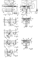
- Figur 1 eine Ansicht einer erfindungsgemäßen Biegevorrichtung, in Querdrahtrichtung betrachtet;
Figur 2 eine Ansicht der gleichen Vorrichtung, in Längsdrahtrichtung betrachtet; dieFiguren 3 bis 6 das schwenkbare Biegewerkzeug in verschiedenen Phasen des Biegevorganges;Figur 7 die Biegeschablone in ihrer Ruhestellung am Beginn ihrer Eingriffsbewegung zum Gitter, undFigur 8 die Biegeschablone in ihrer Arbeitsstellung am Beginn ihrer Rückzugbewegung aus einer fertig geformten Gitterschlaufe.
- Figure 1 is a view of a bending device according to the invention, viewed in the transverse wire direction;
- Figure 2 is a view of the same device, viewed in the longitudinal wire direction; the
- Figures 3 to 6, the pivotable bending tool in different phases of the bending process;
- Figure 7 shows the bending template in its rest position at the beginning of its engagement movement to the grid, and
- Figure 8 shows the bending template in its working position at the beginning of its retraction movement from a fully formed lattice loop.
Das zu bearbeitende Gitter besteht aus Längsdrähten L und Querdrähten Q, deren über die Randlängsdrähte überstehende Endteile E zu Schlaufen S gebogen werden sollen. Die Biegevorrichtung weist eine um ihre Achse X-X in beiden Richtungen auf Drehbewegung antreibbare Welle 1 auf, die zusammen mit einem seitlichen Tragarm oder, wie dargestellt, einer stirnseitig angesetzten Scheibe 5 als Träger für das bewegliche Biegewerkzeug 4 dient und der in axialer Flucht eine Biegeschablone 2, z.B. in Form eines Dornes mit Kreissegmentquerschnitt (vgl. die Draufsichten nach den Figuren 3 bis 6), gegenübersteht. Die Biegeschablone 2 ist, zweckmäßig durch einen hydraulisch oder pneumatisch angetriebenen Kolben 3, zwischen einer in den Figuren 1, 2 und 8 gezeigten Arbeitsstellung, in welcher sich die Stirnflächen der Trägerscheibe 5 und der Biegeschablone 2 vorzugsweise berühren, und einer in Figur 7 gezeigten Ruhestellung, in welcher zwischen den Stirnflächen dieser beiden Elemente ein das Durchtreten eines Querdrahtes Q gestattender Spalt gebildet wird, verschiebbar.The grid to be machined consists of longitudinal wires L and transverse wires Q, the end parts E of which protrude beyond the longitudinal edge wires are to be bent into loops S. The bending device has a shaft 1 which can be driven in rotation about its axis XX in both directions and which, together with a lateral support arm or, as shown, a
Das Biegewerkzeug 4 ist bezüglich der gemeinsamen Achse X-X der Welle 1 und der Biegeschablone 2 exzentrisch an der mit der Welle 1 koaxialen kreisförmigen Trägerscheibe 5 angebracht, welche mit der Welle 1 drehfest verbunden ist und deren dem Gitter zugewandte Stirnfläche mit der Stirnfläche der Biegeschablone in deren Arbeitsstellung koplanar ist.The
Die der Biegeschablone 2 zugewandte Stirnfläche des Biegewerkzeuges 4 ist mit der Stirnfläche der in Ruhestellung befindlichen Biegeschablone zumindest angenähert koplanar, so daß sie sich beim Biegevorgang, wie besonders deutlich aus Figur 2 ersichtlich ist, über den Randlängsdraht L des Gitters hinwegbewegen kann.The end face of the
Der Antrieb der Welle 1 auf Drehung erfolgt durch einen nur schematisch dargestellten Motor 6, beispielsweise durch einen schnellaufenden hydraulischen Motor über eine Schnecke und ein Schneckenrad; besonders empfiehlt sich jedoch ein über eine Zahnstange auf ein Zahnritzel einwirkender Kolbenantrieb.The shaft 1 is driven for rotation by a
Bei einer bevorzugten Ausführungsform der Erfindung ist die Biegeschablone 2 in einem Lagerblock 7 axial verschiebbar geführt, dessen dem Gitter zugekehrte Fläche als Stützfläche für die Gitterquerdrähte ausgebildet ist, wobei in diese Fläche eine Nut 8 zur Auf- nahme eines Randlängsdrahtes des Gitters eingearbeitet ist.In a preferred embodiment of the invention, the
Diese Stützfläche ist koplanar mit derStirnfläche der Biegeschablone in deren Ruhestellung (Figur 7).This support surface is coplanar with the end face of the bending template in its rest position (Figure 7).
Sobald ein Gitterquerdraht Q in die richtige Lage für einen Biegevorgang vorgeschoben worden ist - wobei dieses Vorschieben zweckmäßig unmittelbar durch die Vorschuborgane der Gitterschweißmaschine erfolgt - wird die Biegeschablone 2 von dem Kolben 3 aus ihrer Ruhestellung in Richtung des Pfeiles P1 in Figur 7 in ihre Arbeitsstellung (Figuren 1 und 2) gebracht, was der in Figur 3 gezeigten Ausgangslage für den Biegevorgang entspricht. Nun tritt der Motor 6 in Tätigkeit und schwenkt das Biegewerkzeug 4 in Richtung des Pfeiles P2 in Figur 4, wobei der Draht um die Biegeschablone 2 gebogen wird. Sobald der Biegevorgang beendet ist, kehrt das Biegewerkzeug gemäß Pfeil P3 in Figur 5 seine Bewegungsrichtung um und gleichzeitig zieht der Kolben 3 die Biegeschablone 2 in Richtung des Pfeiles P4 in Figur 8 in ihre Ruhestellung zurück, wodurch die soeben gebogene Schlaufe S' sowohl vom Biegewerkzeug 4 als auch von der Biegeschablone 2 freigegeben wird, so daß das Gitter neuerlich in Richtung des Pfeiles P5 in Figur 6 vorgeschoben werden kann. Bei dieser Vorschubbewegung folgt der nächste zu biegende Querdraht unmittelbar dem zurücklaufenden Biegewerkzeug; die beiden Bewegungen sind also zeitlich überlagert und das Biegewerkzeug 4 bildet, sobald es seine Endlage erreicht hat, einen Anschlag für den sich vorbewegenden Querdraht Q und hält diesen so in der Ausgangslage für einen neuerlichen Biegevorgang fest.As soon as a grid cross wire Q has been pushed into the correct position for a bending process - this pushing advantageously being carried out directly by the feed elements of the grid welding machine - the
Bei einer bevorzugten Ausführungsform ist die gesamte Vorrichtung auf Rollen 9 längs Schienen 10, zweckmäßig gleichfalls durch einen hydraulisch angetriebenen Kolben 11, parallel zur Gittervorschubrichtung verschiebbar, um ihre Wirkstellung unterschiedlichen Querdrahtteilungen des Gitters anpassen zu können.In a preferred embodiment, the entire device on
Die Steuerung der beschriebenen Vorgänge erfolgt zweckmäßig über elektrohydraulische Schaltventile, die unmittelbar von der Folgesteuerung der Schweißmaschine gesteuert werden, um die Biegevorrichtung mit der Schweißmaschine voll zu synchronisieren.The processes described are expediently controlled via electrohydraulic switching valves which are controlled directly by the sequence control of the welding machine in order to fully synchronize the bending device with the welding machine.
Claims (4)
Applications Claiming Priority (2)
| Application Number | Priority Date | Filing Date | Title |
|---|---|---|---|
| AT3190/82 | 1982-08-23 | ||
| AT0319082A AT377713B (en) | 1982-08-23 | 1982-08-23 | BENDING DEVICE FOR WIRE OR TAPE-SHAPED MATERIAL |
Publications (3)
| Publication Number | Publication Date |
|---|---|
| EP0101675A2 true EP0101675A2 (en) | 1984-02-29 |
| EP0101675A3 EP0101675A3 (en) | 1984-04-25 |
| EP0101675B1 EP0101675B1 (en) | 1986-11-12 |
Family
ID=3546742
Family Applications (1)
| Application Number | Title | Priority Date | Filing Date |
|---|---|---|---|
| EP83890136A Expired EP0101675B1 (en) | 1982-08-23 | 1983-08-19 | Bending device for material in wire or strip form |
Country Status (4)
| Country | Link |
|---|---|
| US (1) | US4526025A (en) |
| EP (1) | EP0101675B1 (en) |
| AT (1) | AT377713B (en) |
| DE (1) | DE3367540D1 (en) |
Cited By (5)
| Publication number | Priority date | Publication date | Assignee | Title |
|---|---|---|---|---|
| DE3508809A1 (en) * | 1985-03-12 | 1986-09-25 | Alpha Maschinenbau AG, Zürich | BENDING DEVICE |
| FR2634676A1 (en) * | 1988-07-26 | 1990-02-02 | Alpha Maschinenbau Ag | DEVICE FOR FOLDING LONG-FORMED MATERIALS SUCH AS METALLIC WIRES, BANDED MATERIALS OR PROFILES |
| WO1993001904A1 (en) * | 1991-07-17 | 1993-02-04 | Evg Entwicklungs- Und Verwertungsgesellschaft M.B.H. | Machine for making latticework mats consisting of welded longitudinal and transverse wires |
| WO1993016825A1 (en) * | 1992-02-20 | 1993-09-02 | Evg Entwicklungs- U. Verwertungs-Gesellschaft M.B.H. | Process and installation for producing reinforcement wire meshes |
| CN106001317A (en) * | 2016-06-30 | 2016-10-12 | 中国五冶集团有限公司 | Steel bar bender |
Families Citing this family (8)
| Publication number | Priority date | Publication date | Assignee | Title |
|---|---|---|---|---|
| US4778439A (en) * | 1987-06-18 | 1988-10-18 | Peerless Machine & Tool Corporation | Apparatus and method for forming a clamshell assembly |
| US5271260A (en) * | 1992-06-16 | 1993-12-21 | Oetlinger Tool Engineering Co., Inc. | Bending device for forming carton blanking tools |
| US5697131A (en) * | 1996-06-04 | 1997-12-16 | Hunt; Gerald S. | Money clip |
| GR1003857B (en) * | 2001-02-22 | 2002-04-05 | Method and machine for the production of reinforcement and dowel side frames for concrete reinforcement from wire or rod or other material of prismatic cross section | |
| US20070095006A1 (en) * | 2005-11-01 | 2007-05-03 | Konersmann Ronald D | Lightweight portable concrete enclosure and associated method of construction |
| US7832250B2 (en) * | 2008-04-18 | 2010-11-16 | L&P Property Management Company | Method and apparatus for automating production of sinuous springs |
| GR1007955B (en) | 2011-12-22 | 2013-08-19 | Αντωνιος Παναγιωτη Αναγνωστοπουλος | Method and system for the production of reinforcement dowel bearers |
| CN104985055B (en) * | 2015-07-15 | 2017-12-01 | 成都天创精密模具有限公司 | A kind of eccentric wheel bending mechanism |
Citations (4)
| Publication number | Priority date | Publication date | Assignee | Title |
|---|---|---|---|---|
| DE2215490A1 (en) * | 1972-03-29 | 1973-10-04 | Peddinghaus Carl Ullrich Dr | BENDING MACHINE FOR CONCRETE STEEL BARS IN PARTICULAR |
| AT314319B (en) * | 1972-04-12 | 1974-03-25 | Evg Entwicklung Verwert Ges | Bending machine for wire or ribbon material |
| DE2613264A1 (en) * | 1974-05-07 | 1976-10-28 | Remigio Del Fabro | BENDING DEVICE WITH A RECESSING PROFILED CENTRAL BENDING PIECE FOR AUTOMATIC BENDING MACHINES FOR WIRES AND BARS MADE OF METAL |
| CH592481A5 (en) * | 1973-12-03 | 1977-10-31 | Campagna Giuseppe | Fixture for bending concrete reinforcement bars - has anvil and bending mandrel and crops bar after last bend |
Family Cites Families (6)
| Publication number | Priority date | Publication date | Assignee | Title |
|---|---|---|---|---|
| US2097193A (en) * | 1936-11-04 | 1937-10-26 | Emil Goetz | Wire bending machine |
| DE925404C (en) * | 1950-09-21 | 1955-03-21 | P A Rentrop Akt Ges | Machine for the production of flat springs made of wave-shaped bent wire |
| US3273371A (en) * | 1963-12-23 | 1966-09-20 | Permaduc Inc | Fabricating table |
| US3803893A (en) * | 1971-08-17 | 1974-04-16 | P Peddinghaus | Process for multiple bending of rods and a bending machine for carrying out this process |
| IT976700B (en) * | 1973-02-16 | 1974-09-10 | Del Fabro M | COMPLEX BENDING AND OR SHAPING MACHINE FOR METAL BARS EQUIPPED WITH OPERATING UNITS AND MOBILE BENDING UNITS |
| DE2715178A1 (en) * | 1976-04-07 | 1977-10-27 | Jacob Pieter Schuler | HAND TOOL FOR BENDING PIPES |
-
1982
- 1982-08-23 AT AT0319082A patent/AT377713B/en not_active IP Right Cessation
-
1983
- 1983-08-18 US US06/524,299 patent/US4526025A/en not_active Expired - Fee Related
- 1983-08-19 DE DE8383890136T patent/DE3367540D1/en not_active Expired
- 1983-08-19 EP EP83890136A patent/EP0101675B1/en not_active Expired
Patent Citations (4)
| Publication number | Priority date | Publication date | Assignee | Title |
|---|---|---|---|---|
| DE2215490A1 (en) * | 1972-03-29 | 1973-10-04 | Peddinghaus Carl Ullrich Dr | BENDING MACHINE FOR CONCRETE STEEL BARS IN PARTICULAR |
| AT314319B (en) * | 1972-04-12 | 1974-03-25 | Evg Entwicklung Verwert Ges | Bending machine for wire or ribbon material |
| CH592481A5 (en) * | 1973-12-03 | 1977-10-31 | Campagna Giuseppe | Fixture for bending concrete reinforcement bars - has anvil and bending mandrel and crops bar after last bend |
| DE2613264A1 (en) * | 1974-05-07 | 1976-10-28 | Remigio Del Fabro | BENDING DEVICE WITH A RECESSING PROFILED CENTRAL BENDING PIECE FOR AUTOMATIC BENDING MACHINES FOR WIRES AND BARS MADE OF METAL |
Cited By (8)
| Publication number | Priority date | Publication date | Assignee | Title |
|---|---|---|---|---|
| DE3508809A1 (en) * | 1985-03-12 | 1986-09-25 | Alpha Maschinenbau AG, Zürich | BENDING DEVICE |
| FR2634676A1 (en) * | 1988-07-26 | 1990-02-02 | Alpha Maschinenbau Ag | DEVICE FOR FOLDING LONG-FORMED MATERIALS SUCH AS METALLIC WIRES, BANDED MATERIALS OR PROFILES |
| WO1993001904A1 (en) * | 1991-07-17 | 1993-02-04 | Evg Entwicklungs- Und Verwertungsgesellschaft M.B.H. | Machine for making latticework mats consisting of welded longitudinal and transverse wires |
| US5316052A (en) * | 1991-07-17 | 1994-05-31 | Evg Entwicklungs- U. Verwertungs-Gesellschaft M.B.H. | Machine for making wire lattice mats of welded longitudinal and cross wires with welded end loops |
| WO1993016825A1 (en) * | 1992-02-20 | 1993-09-02 | Evg Entwicklungs- U. Verwertungs-Gesellschaft M.B.H. | Process and installation for producing reinforcement wire meshes |
| US5446254A (en) * | 1992-02-20 | 1995-08-29 | Evg Entwicklungs- U. Verwertungs-Gesellschaft M.B.H. | Process and installation for producing reinforcement wire meshes |
| AT402033B (en) * | 1992-02-20 | 1997-01-27 | Evg Entwicklung Verwert Ges | METHOD AND SYSTEM FOR PRODUCING REINFORCEMENT GRIDS |
| CN106001317A (en) * | 2016-06-30 | 2016-10-12 | 中国五冶集团有限公司 | Steel bar bender |
Also Published As
| Publication number | Publication date |
|---|---|
| AT377713B (en) | 1985-04-25 |
| ATA319082A (en) | 1984-09-15 |
| DE3367540D1 (en) | 1987-01-02 |
| US4526025A (en) | 1985-07-02 |
| EP0101675A3 (en) | 1984-04-25 |
| EP0101675B1 (en) | 1986-11-12 |
Similar Documents
| Publication | Publication Date | Title |
|---|---|---|
| EP0101675B1 (en) | Bending device for material in wire or strip form | |
| DE2514187A1 (en) | MACHINE FOR MANUFACTURING IRONS OR BENDING MACHINE | |
| DE2822476A1 (en) | DEVICE FOR CUTTING LONG PROFILE MATERIALS, IN PARTICULAR PIPE MATERIAL | |
| DE2950120C2 (en) | ||
| DE2610467A1 (en) | DEVICE FOR CUTTING PIPES | |
| EP2543452A1 (en) | Bending device for rod-shaped workpieces | |
| EP0079587A1 (en) | Wire-bending machine | |
| AT401360B (en) | BENDING SYSTEM FOR BARS | |
| DE2319426A1 (en) | BENDING MACHINE FOR ROD OR STRIP-SHAPED MATERIAL | |
| DE2723846A1 (en) | BENDING MACHINE FOR WIRE | |
| DE3117293C2 (en) | ||
| DE3102766C2 (en) | Metal band saw | |
| DE2051779C3 (en) | Device for trimming and then joining the ends of consecutive tapes | |
| DE3738059C1 (en) | Automatic lathe with drivable tool head and guide device for material bars | |
| EP0622136B1 (en) | Device for the production of reinforcement meshes for concrete panels | |
| DE2113196C3 (en) | Method and machine for manufacturing wire mesh by friction welding | |
| EP0549761B1 (en) | Machine for making latticework mats consisting of welded longitudinal and transverse wires | |
| EP2789406B2 (en) | Bending machine | |
| DE2843531C2 (en) | Machine for the production of lattice girder-like reinforcement structures for reinforced concrete | |
| EP1351783A1 (en) | Device for cutting metal strips to length | |
| DE7416105U (en) | Device for joining two lengths of strip or sheet metal at the end by flash welding | |
| DE3034469A1 (en) | TRANSPORT DEVICE FOR WORKPIECES | |
| DE3341714C2 (en) | ||
| EP3126072B1 (en) | Dressing apparatus | |
| DE3504713C2 (en) |
Legal Events
| Date | Code | Title | Description |
|---|---|---|---|
| PUAI | Public reference made under article 153(3) epc to a published international application that has entered the european phase |
Free format text: ORIGINAL CODE: 0009012 |
|
| PUAL | Search report despatched |
Free format text: ORIGINAL CODE: 0009013 |
|
| AK | Designated contracting states |
Designated state(s): CH DE FR GB IT LI |
|
| AK | Designated contracting states |
Designated state(s): CH DE FR GB IT LI |
|
| 17P | Request for examination filed |
Effective date: 19840607 |
|
| ITF | It: translation for a ep patent filed |
Owner name: BARZANO' E ZANARDO MILANO S.P.A. |
|
| GRAA | (expected) grant |
Free format text: ORIGINAL CODE: 0009210 |
|
| AK | Designated contracting states |
Kind code of ref document: B1 Designated state(s): CH DE FR GB IT LI |
|
| REF | Corresponds to: |
Ref document number: 3367540 Country of ref document: DE Date of ref document: 19870102 |
|
| ET | Fr: translation filed | ||
| PLBE | No opposition filed within time limit |
Free format text: ORIGINAL CODE: 0009261 |
|
| STAA | Information on the status of an ep patent application or granted ep patent |
Free format text: STATUS: NO OPPOSITION FILED WITHIN TIME LIMIT |
|
| 26N | No opposition filed | ||
| ITTA | It: last paid annual fee | ||
| PGFP | Annual fee paid to national office [announced via postgrant information from national office to epo] |
Ref country code: FR Payment date: 19940729 Year of fee payment: 12 |
|
| PGFP | Annual fee paid to national office [announced via postgrant information from national office to epo] |
Ref country code: GB Payment date: 19940809 Year of fee payment: 12 |
|
| PGFP | Annual fee paid to national office [announced via postgrant information from national office to epo] |
Ref country code: DE Payment date: 19941028 Year of fee payment: 12 |
|
| PG25 | Lapsed in a contracting state [announced via postgrant information from national office to epo] |
Ref country code: GB Effective date: 19950819 |
|
| GBPC | Gb: european patent ceased through non-payment of renewal fee |
Effective date: 19950819 |
|
| PG25 | Lapsed in a contracting state [announced via postgrant information from national office to epo] |
Ref country code: FR Effective date: 19960430 |
|
| PG25 | Lapsed in a contracting state [announced via postgrant information from national office to epo] |
Ref country code: DE Effective date: 19960501 |
|
| REG | Reference to a national code |
Ref country code: FR Ref legal event code: ST |
|
| PGFP | Annual fee paid to national office [announced via postgrant information from national office to epo] |
Ref country code: CH Payment date: 20020827 Year of fee payment: 20 |
|
| PG25 | Lapsed in a contracting state [announced via postgrant information from national office to epo] |
Ref country code: LI Free format text: LAPSE BECAUSE OF EXPIRATION OF PROTECTION Effective date: 20030818 Ref country code: CH Free format text: LAPSE BECAUSE OF EXPIRATION OF PROTECTION Effective date: 20030818 |
|
| REG | Reference to a national code |
Ref country code: CH Ref legal event code: PL |