EP0091876A1 - Dispositif de prise d'empreinte par des moyens optiques, notamment en vue de la réalisation automatique de prothèses - Google Patents
Dispositif de prise d'empreinte par des moyens optiques, notamment en vue de la réalisation automatique de prothèses Download PDFInfo
- Publication number
- EP0091876A1 EP0091876A1 EP83420065A EP83420065A EP0091876A1 EP 0091876 A1 EP0091876 A1 EP 0091876A1 EP 83420065 A EP83420065 A EP 83420065A EP 83420065 A EP83420065 A EP 83420065A EP 0091876 A1 EP0091876 A1 EP 0091876A1
- Authority
- EP
- European Patent Office
- Prior art keywords
- analysis
- optical
- sensor
- prosthesis
- analyzed
- Prior art date
- Legal status (The legal status is an assumption and is not a legal conclusion. Google has not performed a legal analysis and makes no representation as to the accuracy of the status listed.)
- Granted
Links
Images


Classifications
-
- G—PHYSICS
- G05—CONTROLLING; REGULATING
- G05B—CONTROL OR REGULATING SYSTEMS IN GENERAL; FUNCTIONAL ELEMENTS OF SUCH SYSTEMS; MONITORING OR TESTING ARRANGEMENTS FOR SUCH SYSTEMS OR ELEMENTS
- G05B19/00—Programme-control systems
- G05B19/02—Programme-control systems electric
- G05B19/42—Recording and playback systems, i.e. in which the programme is recorded from a cycle of operations, e.g. the cycle of operations being manually controlled, after which this record is played back on the same machine
- G05B19/4202—Recording and playback systems, i.e. in which the programme is recorded from a cycle of operations, e.g. the cycle of operations being manually controlled, after which this record is played back on the same machine preparation of the programme medium using a drawing, a model
- G05B19/4207—Recording and playback systems, i.e. in which the programme is recorded from a cycle of operations, e.g. the cycle of operations being manually controlled, after which this record is played back on the same machine preparation of the programme medium using a drawing, a model in which a model is traced or scanned and corresponding data recorded
-
- A—HUMAN NECESSITIES
- A61—MEDICAL OR VETERINARY SCIENCE; HYGIENE
- A61C—DENTISTRY; APPARATUS OR METHODS FOR ORAL OR DENTAL HYGIENE
- A61C13/00—Dental prostheses; Making same
- A61C13/0003—Making bridge-work, inlays, implants or the like
- A61C13/0004—Computer-assisted sizing or machining of dental prostheses
-
- A—HUMAN NECESSITIES
- A61—MEDICAL OR VETERINARY SCIENCE; HYGIENE
- A61C—DENTISTRY; APPARATUS OR METHODS FOR ORAL OR DENTAL HYGIENE
- A61C19/00—Dental auxiliary appliances
- A61C19/04—Measuring instruments specially adapted for dentistry
-
- A—HUMAN NECESSITIES
- A61—MEDICAL OR VETERINARY SCIENCE; HYGIENE
- A61C—DENTISTRY; APPARATUS OR METHODS FOR ORAL OR DENTAL HYGIENE
- A61C5/00—Filling or capping teeth
- A61C5/70—Tooth crowns; Making thereof
- A61C5/77—Methods or devices for making crowns
-
- A—HUMAN NECESSITIES
- A61—MEDICAL OR VETERINARY SCIENCE; HYGIENE
- A61C—DENTISTRY; APPARATUS OR METHODS FOR ORAL OR DENTAL HYGIENE
- A61C9/00—Impression cups, i.e. impression trays; Impression methods
- A61C9/004—Means or methods for taking digitized impressions
- A61C9/0046—Data acquisition means or methods
-
- G—PHYSICS
- G16—INFORMATION AND COMMUNICATION TECHNOLOGY [ICT] SPECIALLY ADAPTED FOR SPECIFIC APPLICATION FIELDS
- G16H—HEALTHCARE INFORMATICS, i.e. INFORMATION AND COMMUNICATION TECHNOLOGY [ICT] SPECIALLY ADAPTED FOR THE HANDLING OR PROCESSING OF MEDICAL OR HEALTHCARE DATA
- G16H30/00—ICT specially adapted for the handling or processing of medical images
Definitions
- the present invention relates to an impression taking device by optical means, in particular for the automatic production of a prosthesis, and even more particularly the production of prostheses such as crowns used in dentistry, this application n 'However, not being limiting, in the sense that the device can also be used for establishing an odontological diagnosis which is not followed by the making of a prosthesis.
- the present invention overcomes these drawbacks by providing three-dimensional analysis means, suitable for all odontological and medical applications, by specifying the means making it possible to analyze the image and to provide a signal directly usable by a machine tool. with numerical control, this in a very fast way while offering a possibility of verification of the quality of analysis, and by allowing the automatic machining of a complete prosthesis only from the optical impression produced and algorithms of work, without any intermediate intervention in the mouth or on another part of the body to receive the prosthesis, the means provided being economically advantageous insofar as they have a wide field of application and bring an effective saving of time and labor. of work.
- the subject of the present invention is a device for taking an impression by optical means, in particular for the automatic production of prostheses, this device essentially comprising, in combination, means emitting light waves or non-traumatic acoustic means for directing said waves onto the part of the body, such as the location of the tooth, to be analyzed, means for receiving light or acoustic waves reflected by this part of the body, directing said waves onto a sensor associated with a analog-digital converter, making it possible to obtain, in the form of digital signals, a representation of the shape, in three dimensions of space, of the part of the body to be analyzed, and of the means of analysis and processing of the digital signals obtained , in particular for the automatic control of a numerically controlled machine tool for the machining of a prosthesis, such as a dental prosthesis adapted exactly to the part of the body analyzed.
- the device according to the invention makes it possible to capture all the shape characteristics of the area to be analyzed by means of a purely "optical” nature, excluding photographic analysis, the term “optical” including here as well the use of typically optical waves as the use of acoustic waves, as long as these waves allow direct analysis in three dimensions, and are of course not traumatic for the tissues of the analyzed part of the patient's body.
- the sensor and converter used must correspond to the type of wave used, and the assembly must make it possible to detect shape details with sufficient precision, for example less than or equal to a millimeter.
- the device advantageously comprises a laser source, at least one optical fiber and a lens for directing the incident beam towards the part of the body to be analyzed, at least one other lens and another optical fiber to collect the reflected beam and direct it onto the sensor associated with the analog-digital converter, and an optical system such as a semi-transparent mirror and lens, further directing on said sensor a reference beam, for analysis by wave interference.
- the assembly can comprise a single optical fiber guiding both the incident beam and the reflected beam, and it is also possible to remove any optical fiber, if the analysis head includes the light source and the sensor, with the lenses always necessary and is connected by purely electrical connections with an external box including the power supply and the analog-digital converter.
- a particular method avoiding the stripping of the hologram or its reading consists in using a laser emitting two rays of slightly different wavelengths almost simultaneously or simultaneously by the nonlinear optical passage (through mineral or organic crystals), in brief impulses or weak intensities continuously. This allows the creation of "contour lines" which can be analyzed by conventional skeletonization software.
- optical fibers can still be used, but the assembly must also include, to allow analysis by holographic interferometry, tracking frames, associated respectively with the emitting source and the sensor. , and means making it possible to determine or fix the distance between the optical means of the analysis head and a reference plane linked to the part of the body to be analyzed.
- a first solution called “dynamic” consists in placing on the analysis head an ultrasonic or infrared transmitter-receiver determining the distance to the reference plane at the precise moment when the lighting is carried out for
- a second solution known as “static”, consists in providing on the head of analysis a reference of known length, intended to rest on a point of the part of the body to be analyzed.
- optical fibers with an index gradient in order to simplify or even eliminate all the lenses located towards the object or the camera.
- This system is applicable both in coherent light and in non-coherent light.
- Mirror systems and more or less "wide” optics, allow the analysis of more or less large areas, which may have faces oriented differently from one another, or faces which cannot be directly lit and / or observed. .
- the sensor reached by the reflected beam and also possibly by a reference beam, is advantageously of the charge transfer photosensor type, in particular a photosensor of the matrix CCD type, or even a modified vidicon tube.
- the advantage of the CCD photosensor on the vidicon system is that it provides a plan-by-plan analysis; on the other hand the number of gray levels is lower there, currently.
- the analysis is done by fixing the coordinates according to two dimensions, for example at points corresponding to intervals of 20 fA, and by varying only the coordinates according to the third dimension from space.
- information storage means are inserted between the sensor and the analog-to-digital converter itself, which delivers to the processing means "point by point” output signals, transformed by an interface for their adaptation to the digital processing means, means for viewing the data entered being further provided, in conjunction with the aforementioned storage means.
- the visualization should preferably be provided, for information and verification, in order to be able to assess whether the optical impression produced is total, precise, usable and taken on preparatory work (size of a tooth stump) carried out correctly. More particularly, visualization is advantageous before analog-digital conversion, in order to limit the field of action (deletion of information deemed unnecessary) and verification of the quality of data entry.
- the visualization of the image in its form obtained after analog-digital conversion is also useful, to assess line by line the accuracy of the data. The choice of the best image, to be retained for subsequent digital processing, may be manual and facilitated by interactive viewing, or even be entirely automatic.
- the real occlusion can be determined not only by taking an optical impression but also by a facial and oral analysis of the patient on whom we have previously placed a certain number of buccal landmarks, avoiding a study of the temporal-maxillary articulation by the conventional, very costly, means of the articulator.
- Occlusion can be determined by locating the upper and lower jaws, taking optical impressions separate from the two jaws, making an anterior optical screen of the landmarks of the two jaws, and joining the two jaws thanks to their location at the level of the claie.
- the tools must obviously be adapted to the dimensions and curvatures of the prosthetic parts to be made, including the rough must be rigidly fixed so as to avoid vibrations and to provide a reference point during machining.
- the known principles of programming, tracking, and servo-control for the use of numerically controlled machine tools will apply without difficulty, the machining preferably being carried out under visual control of its different phases by the display means. mentioned above.
- the time required to machine a crown can be estimated at 5 minutes; the complete realization of a crown, including the optical impression, the data processing and the machining itself, should not exceed a total duration of 15 minutes, while the time required is currently around a week, with more than 3 hours of actual work by dentists and prosthetists, referring to the classic "lost wax" process.
- the actual working time is therefore divided by 12, and the time between taking an impression and placing the prosthesis is divided by 600, while improving the biological and physiological conditions of the operation since the patient will be able to leave with his reconstituted tooth 15 mm after the end of the pruning.
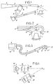
- Figure 1 shows that for this purpose we can use a laser (2) as a coherent light source, which after passing through a filter (3) is directed, by a first optical fiber (4), to the area of stump (1) to be analyzed.
- the incident wave beam is dispersed over the area to be analyzed by a lens (5), attached to the end of the optical fiber (4).
- Another lens (6) concentrates the reflected beam, to collect it in a second optical fiber (7) which directs it onto a sensor (8), associated with an analog-digital converter (9).
- a semi-transparent mirror (10) interposed on the path of the incident beam, deflects a fraction of the latter to obtain a reference beam (11), which another lens (12) concentrates on the sensor (8).
- the analysis head (13) may have two receptive lenses (6 'and 6 "), fixed respectively to the ends of two optical fibers (7' and 7") which guide the reflected beam, divided here into two fractions (see Figure 2). Two opposite sides of the stump (1) can thus be analyzed simultaneously.
- the analysis head (13) is provided with a holding handle (14) and connected by optical fibers (4 and 7), to a housing (15) located outside the mouth and containing the emitting source. (2) as well as the sensor (8) and the converter (9), which allows the use of an efficient laser (see Figure 3).
- optical fibers (4 and 7, or 7 'and 7 "), must be sheathed to avoid any ocular risks.
- FIG 4 illustrates the principle of an apparatus not using a coherent light source.
- the wave emitting means generally designated by the reference (16), here comprise a light source (17), for example halogen, a light capacitor (18), a tracking frame (19) and a lens ( 20).
- the wave receiving means generally designated by the reference (21), include a lens (20a), a reference frame (19a) and the sensor (8), always associated with the analog-digital converter.
- the two marking frames (19 and 23) for example of the "micro moiré" type, must have a known pitch to within 10 - 1 mm at least.
- the number of fringes or grid lines must be determined with precision (from 1mm to 10 - 3 mm, the ideal value being 10 _ 2 mm).
- the distance between the two optical centers must be known to the nearest 0.5 mm, and the focal length must be known to the nearest mm. These various factors are fixed and defined constructively.
- the "moiré" can present, for the analysis of the teeth, a problem of reflection, due to the fact that the incident light is of white type. To avoid this, we will work in a range of waves not corresponding to any color present in the mouth, by placing for example a filter allowing to work in blue or green, or between green and blue. It remains to determine or fix the distance separating the analysis plane of the sensor (8) from the reference plane, always to be located below the lower edge of the future crown, this last distance having to be known to the nearest mm.
- One solution consists in fixing, on the analysis head (13), a needle (22) of suitably chosen length, intended to bear on the tooth stump (1) to be analyzed, as shown in FIG. 5 representing an assembly practice corresponding to the principle of Figure 4, and using optical fibers (4,7 ', 7 ") and lenses (5,6'.6") as in the previous case of a coherent light source.
- FIG. 6 Another possible assembly is illustrated in FIG. 6, where a single optical fiber (23), carrying a lens (24) at its end provided with the needle (22), simultaneously guides the incident beam and the reflected beam, the latter being returned by a semi-transparent mirror (25) to the sensor (8) associated with the converter (9).
- the optical fibers can also be eliminated, as shown in FIG. 7, by producing an analysis head (13) including the light source (17) and the sensor (8), on which the respective lenses (5 and 6).
- This head (13) is connected by electrical connections (26 and 27) to a power supply (28) and to the analog-digital converter (9), belonging to an external box (29).
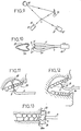
- a system of two mirrors (30 and 31), added to the optical system produced according to the principles described above, makes it possible to deflect the incident beam, and the reflected beam, so as to allow the analysis of the face of the object (1) opposite the side directly accessible by the source (17) and the sensor (8).
- FIGS. 10 et seq. Show how the optical system can be adapted to the analysis of a larger area, in this case including the upper arch (33) and / or lower arch (34), in order to analyze these arches with a view to locating the entire prosthesis in the oral environment.
- the principles of embodiment of the device remain unchanged: a housing (15) is connected, by an optical fiber (4), to a lens (5) diffusing the incident beam, while other lenses (6 'and 6 " ) are fixed at the starting point of the optical fibers (7 'and 7 ") which guide the reflected beams.
- the optic must be wider, and the needle (22), when this solution is used in the case of use of non-coherent waves, must be adapted to the optic and to the chosen fulcrum .
- a palatal support see FIG. 11
- a dental support FIG. 12
- a vestibular support not shown.
- Markers can be placed in particular on the teeth (incisors and premolars), at the base of the lower jaw, and at the level of the condyle or the auditory hole, to perform a dynamic analysis, with progressive movements of the jaw (movements in occlusion and extremes ).
- ultrasound waves In medical applications of high surgery, digital information can be obtained from a radiological analysis reconstituted in three dimensions, or by coupling on a scanner, or by vector correlation on an X-ray image, or even by ultrasound. If it is certain that we can accept ultrasound for obtaining the optical impression of a dental form, as a variant of the solutions described above, the use of ultrasound waves is advantageous especially in determining the outline of an organ.
- the ultrasound wave generator (35) directed towards the object (1) to be analyzed must be controlled by a clock (36) providing a time base, and the reception of the signals reflected by the sensor (8), associated with the converter (9), takes place via a translator (37) and / or an amplifier (38).
- the correction will be made by joining the most extreme points while respecting the curvature of the most neighboring points, the number of points determining this curvature being a function of the precision of the method.
- Another modification consists in increasing the values according to the requirements of the insertion of the prosthesis (small undercuts) and the physical properties of the cement of sealing used. If "memory" metals are used, this latter operation becomes unnecessary.
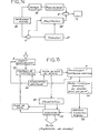
- FIG. 15 shows in more detail the means for receiving the reflected waves and for analog-digital conversion, allowing rapid and repetitive optical analysis, with simultaneous viewing to allow the choice of the best image.
- the sensor (8) receiving the beam reflected by the object to be analyzed, is here a photosensor of the matrix CCD type, delivering information which is stored in (39) before arriving at the analog-digital converter proper (9), these different parts having all their specific power supplies indicated in (40).
- the converter (9) is connected to an output circuit (41), connected by an interface (42) to the computer (43).
- display means (44) produced in the form of a "video" monitor screen, preferably with color image, are interactively connected to the storage circuits (43), to control the transfer of information to the converter (9).
- the CCD photosensor analysis system requires at least 100 gray levels with an "anti-blowing" system, to obtain sufficient information.
- the coordinates "x” and “y” are automatically given in the plan. They are subsequently corrected according to the focal length of the analysis used, and the distance of the point considered from the optical axis.
- the "z" coordinate is the result of a Fourier-type transformation, in coherent waves as in non-coherent waves (with the use of a tracking frame in the latter case).
- the mathematical algorithms to be used here are currently known.
- the envelope of the future crown (45) that is to say the volume inside which it must be registered.
- This volume is defined by planes, inter alia an anterior plane (46) and a posterior plane (47), theoretically tangent to the adjacent teeth (48 and 49), at the points of contact with the tooth to be reconstituted, and the practical determination of which can take taking into account corrective factors, due to physiological movements and the diastema.
- the volume in question is also delimited by a palatal or lingual lateral plane (50), and by a vestibular lateral plane (51), tangent, both with the anterior (48) and posterior (49) teeth;
- corrective factors can be involved, linked to the type of tooth to be reconstructed, these factors being able to be decreasing, for example in the case of an upper lateral incisor.
- substantially parallelepipedic in which the theoretical crown is inscribed, it remains to define a lower plane, given by the singular limit of the crown, drawn automatically or manually on a monitor, and an upper or occlusal plane. , determined in occlusion and defined as the plane passing through the highest point of the occlusal surface of the opposing tooth or, in the absence of the latter, by the upper limit of the anterior and posterior teeth.
- the external shape of the theoretical crown should be adapted, as shown in Figure 17, to the shape and position of the tooth stump (1).
- the operation consists in making the lower edge (A) of the crown (45) coincide, located in the lower plane of the envelope. with the outline (8) of the stump (1), respecting a minimum thickness of material (e) at the lowest point.
- the theoretical external profile of the crown (45 ') undergoes a progressive correction, keeping it a regular curve appearance while allowing it to join the contact zone with the adjacent teeth (48 and 49), on the one hand , and the desired lower limit, on the other hand.
- a first correction to be made consists in centering the gutter of the theoretical tooth on the general line of the gutters of the teeth of the arch.
- a second correction is that of static occlusion; it represents an adaptation to the occlusal surfaces of the opposing teeth such as (52) - Figure 17, captured by means described below.
- a third correction consists in making a mathematical smoothing by including the surface obtained with all the arches in occlusion and by inducing lateral and antero-posterior movements performing a smoothing of the data.
- the envelope can also be determined by the addition of a deformable cap on the stump (1), the upper or occlusal plane being in this case analyzed in three dimensions after having asked the patient to perform all the necessary movements.
- the definition of the envelope is partially different: there is always a lower plane (53), an upper plane (54) and a posterior plane (55), but the lateral and anterior planes are united in a single curved envelope surface (56), which will be determined to be substantially tangent to the gingival ridge, and however spaced from it a few millimeters, this spacing being a function of the most buccal part of the prosthesis (free edge of the incisors or rim of the resin ).
- the lower limit of the surface (56) must be fixed at a non-traumatic depth, depending on the optical imprint defining the lower plane (53).
- the posterior plane (55) will be determined by the anatomical elements situating the theoretical limit of a prosthesis (retro-molar tuberosity, trigone, ).
- the upper plane (54) that is to say the occlusion plane of the prosthesis, will result directly from the determination of the actual occlusion, described below with reference to FIGS. 19 and following.
- optical impressions of the upper (33) and lower (34) arches are made, as already described above, as well as anterior and lateral optical impressions defining "trays “anterior (57) and lateral (58). Then we proceed to the adjustment of the upper and lower impressions relative to each other, the racks allowing the exact mathematical positioning of one jaw relative to the other, from which occlusion is obtained "static".
- the movements of the jaws can be recorded according to a substantially identical operating mode, by facial analysis of the patient on whom a certain number of buccal marks will have been placed. If this facial analysis is done in X-rays, it is enough to have three radiopaque markers, linked to the jaws and visible to the optical impression taking.
- the analysis table In the case of transmitter marks, the analysis table must be sensitive to the emission wavelength, and the marks must be visible when taking an optical impression. If they are conventional landmarks, they must be visible at all times during the analysis of movements. In each case, the marks must be fixed to within 100 tl, between the start and the end of analysis. If these landmarks are only intraoral, they must be visible at all times during the analysis of movements.
- the flow diagram of FIG. 20 illustrates the execution of this last operation, carried out by carrying out a check by the display means (44).
- the shade of a tooth will be evaluated by a known method of thermography, by using in particular an infrared receiver with large aperture or by causing an infrared illumination.
- the colors determined automatically will be sent, after visualization (in real color), to the memory then to the stock of teeth. This same determination can induce the automatic production of aesthetic surfaces (automatic inclusion of successive layers of resin or ceramic, followed by automatic firing of teeth).
- the calculator will determine the ideal insertion axis, offering maximum stability, as a result of all the dental axes taken separately. Insofar as insertion is impossible, there will be attachment positioning on the most responsible teeth. Finally, the computer will choose the best situation for drawing the hooks or the anchor point for the attachments.
- the optical impression makes it possible to really process the study of moldings automatically. It makes it possible to arrive at a diagnosis, and at the proposal of a treatment tooth by tooth by associating the radiographic, echographic and thermographic data.
- the procedure is therefore identical to that of producing a fixed prosthesis.
- the volume of the pulp chamber will be evaluated in the same way in order to calibrate the instruments.
- the means of investigation proposed by the present invention make it possible to resolve the diagnosis "temporal-maxillary joint / muscle / articular joint", but also that of the tooth with respect to its bone support.
- the bone contour in relation to the dental and mucosal contour will be determined by ultrasound or xerography, and dental mobility will be measured by successive optical impressions.
- the technical means according to the present invention can be used to very precisely locate the position of an included tooth (ultrasound).
- the programming and communication system with the operator must obviously be adapted to the nature of the information processed (numerically defined forms), by allowing the visualization, control and saving of the work, essentially using a desk with alphanumeric keyboard and command of functions, as well as a display screen and interactive graphic means, making it possible to "manipulate” the image .: translation, change of scale, rotation, ...
- the data will be processed quickly, in “real time” , while allowing to store the work carried out, for the constitution of the "customers” file and the execution of other tasks of management of the dental or medical cabinet.
- the images to be processed and the shapes to be machined are essentially reduced to surfaces and volumes.
- Complex surfaces will be defined as an interpolation fraction of a network of points and curves, on which transverse tangency and curvature constraints will be imposed.
- the complex volumes must derive from polyhedral volumes imposed by the limits of the optical envelope and by the possibilities of insertion of the prosthetic part.
- a last less abstract function will be the preparation of the machining by numerical control, starting from the elements stored in the memory, with permanent control, the operator not having to choose the work because it will be preselected (reduced functions).
- the block diagram in Figure 25 summarizes the principle of automatic machining of a prosthesis and machining control.
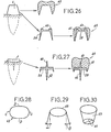
- the support (59) can also, as shown at the bottom of FIG. 26, include fixing points (60), machined for the installation of an aesthetic piece (61) which will exactly cover the support (59), the assembly constituting the crown (45).
- the support (59) may also include a fixing pivot (62), possibly threaded, as shown in FIG. 27.
- the fixing points can be: very rigid axes of precisely determined dimensions, on which will be fixed elements with complementary anchoring forms (in cement, metal ...) - buttons- pressures, damping, ... attachments that can be fixed on the rigid axis and supporting the aesthetic element - screwing systems - bonding means.
- machining can also concern spring fixing points, or a mold produced following a study in cosmetic surgery.
- the machining work consists of modeling by reference to shape geometries.
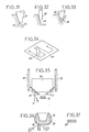
- a conical tool (66) is used, with a half-angle at the top equal to the clearance angle to be obtained, with a spherical end (67) of radius equal to the radius of connection to the background. If the half-angle at the top of the tool is not equal to the draft angle, it is necessary to perform a machining in end of tool (68), by multiplying the number of flank machining passes.
- the bottom planes (64) define the diving limits of the tool (66 or 68) - see figures 31, 32 and 33.
- a tool (69) with a spherical end, of radius equal to the radius of connection of the bottom, will be necessary.
- the machining of the base will be done plane by plane, with linear and parallel passes delimited by the adjacent planes and / or by the side of the crown.
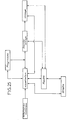
- FIG. 35 A block diagram of the numerically controlled machining machine (70) is given in FIG. 35, in which (71) designates the zone where the work is carried out according to the three coordinates (x, y and z).
- (71) designates the zone where the work is carried out according to the three coordinates (x, y and z).
- magazines (72 and 73) On either side of the machine proper (70), there are magazines (72 and 73) respectively allowing the choice of the material to be machined and the choice of the tool.
- the machine (70) comprises, in association with these magazines, an arm (74) for picking up materials, and an arm (75) for changing tools, allowing transfers between the two magazines (72 and 73) and the area work (71).
- each blank (76) is provided with a fixing lug (77), for its total immobilization on the machine.
- the section of the tenon (77) will for example be rectangular (see FIG. 37).
- the shavings resulting from milling can be recycled by foundry, for a new machining.
Abstract
Description
- La présente invention se rapporte à un dispositif de prise d'empreinte par des moyens optiques, notamment en vue de la réalisation automatique d'une prothèse, et encore plus particulièrement la réalisation de prothèses telles que les couronnes utilisées en art dentaire, cette application n'étant toutefois pas limitative, en ce sens que le dispositif est aussi utilisable pour l'établissement d'un diagnostic odontologique qui n'est pas suivi de la confection d'une prothèse.
- Très peu d'études ont, jusqu'à présent, eu pour objet la prise d'une empreinte par des moyens optiques, dans le domaine de l'art dentaire, et les réalisations concrètes sont actuellement inexistantes. On peut citer le brevet US N° 3 861 044 (SWINSON), document décrivant un procédé qui consiste, pour faire l'empreinte d'une cavité creusée dans une dent et réaliser un insert (ou "inlay") destiné à se loger dans la cavité, en la séquence d'opérations suivante :
- - préparation de la dent défectueuse ;
- - réalisation d'une représentation photographique de la dent avec sa cavité ;
- - transfert d'un signal représentatif de l'image photographiée à une machine-outil commandée automatiquement ;
- - remplissage de la dent préparée avec de la cire ;
- - réalisation d'une nouvelle représentation photographique de la dent, cette fois remplie de cire ;
- - transfert d'un signal représentatif de la nouvelle image photographique à la machine-outil commandée automatiquement ;
- - fonctionnement automatique de la machine-outil à partir des signaux précédents, afin d'usiner un insert dentaire de forme adaptée ;
- - mise en place de l'insert dans la cavité de la dent.
- Cette technique arbitraire, telle qu'elle est décrite dans le document auquel il est ici fait référence, présente de nombreux inconvénients ainsi que des insuffisances diverses :
- 1. Une image photographique ordinaire ne peut représenter qu'en deux dimensions l'objet dont la forme est à analyser. Si l'on veut reconstituer par ce procédé les trois dimensions de l'espace, il faut réaliser un grand nombre de photographies, par exemple de l'ordre du millier au minimum, avec une précision de 100 microns, pour chaque élément à analyser.
- 2. Il n'est pas précisé quelle est la nature des signaux transmis, supposés représentatifs des images photographiques réalisées, et en particulier si ces signaux sont analogiques ou numériques. Or un usinage automatique ne peut se faire qu'au moyen d'une machine-outil à commande numérique, et dans le cas considéré l'on ne voit donc pas concrètement comment la machine pourra effectuer un travail déterminé, ni surtout un positionnement strict de la pièce à usiner, à partir d'images photographiques traduites en des signaux de nature indéfinie.
- 3. Dans le procédé évoqué, le praticien doit remplir la cavité de cire. Cette technique est possible pour les inserts, mais inapplicable à d'autres types courants de prothèses pour dents, notamment les couronnes, ce qui exclut bien évidemment ce genre d'applications.
- 4. De plus, le remplissage de cire et son utilisation constituent une sorte de prise d'empreinte par moulage ; le procédé exige ainsi des opérations matérielles sur la dent à traiter et ne peut s'assimiler à une prise d'empreinte complète par des moyens purement optiques ; le temps de mise en oeuvre reste donc également important. Enfin, le second signal photographique, obtenu à partir de ce remplissage de cire, est toujours aussi imprécis (reconstitution des trois dimensions ?), et cette imprécision se répercute évidemment sur le résultat final obtenu.
- La présente invention remédie à ces inconvénients, en fournissant des moyens d'analyse en trois dimensions, adaptés à toutes applications odontologiques et médicales, en précisant les moyens permettant d'analyser l'image et de fournir un signal directement utilisable par une machine-outil à commande numérique, ceci d'une manière très rapide tout en offrant une possibilité de vérification de la qualité d'analyse, et en permettant l'usinage automatique d'une prothèse complète uniquement à partir de l'empreinte optique réalisée et d'algorithmes de travail, sans aucune intervention intermédiaire en bouche ou sur une autre partie du corps devant recevoir la prothèse, les moyens fournis étant économiquement intéressants dans la mesure où ils comportent un large champ d'application et apportent un gain effectif de temps et de main-d'oeuvre.
- A cet effet, la présente invention a pour objet un dispositif de prise d'empreinte par des moyens optiques, notamment en vue de la réalisation automatique de prothèses, ce dispositif comprenant essentiellement, en combinaison, des moyens émetteurs d'ondes lumineuses ou acoustiques non traumatisantes, des moyens pour diriger lesdites ondes sur la partie du corps, telle qu'emplacement de dent, à analyser, des moyens récepteurs des ondes lumineuses ou acoustiques réfléchies par cette partie du corps, dirigeant lesdites ondes sur un capteur associé à un convertisseur analogique-numérique, permettant d'obtenir sous forme de signaux numériques une représentation de la forme, dans les trois dimensions de l'espace, de la partie du corps à analyser, et des moyens d'analyse et de traitement des signaux numériques obtenus, notamment en vue de la commande automatique d'une machine-outil à commande numérique pour l'usinage d'une prothèse, telle qu'une prothèse dentaire adaptée exactement à la partie du corps analysée.
- Le dispositif selon l'invention permet de saisir toutes les caractéristiques de forme de la zone à analyser par des moyens de nature purement "optique", en excluant l'analyse photographique, le terme "optique" incluant ici aussi bien l'utilisation d'ondes typiquement optiques que l'utilisation d'ondes acoustiques, du moment que ces ondes permettent de réaliser directement une analyse en trois dimensions, et ne sont bien entendu pas traumatisantes pour les tissus de la partie analysée du corps du patient. Le capteur et le convertisseur utilisés doivent correspondre au type d'ondes mis en oeuvre, et l'ensemble doit permettre de relever des détails de forme avec une précision suffisante, par exemple inférieure ou égale au millimètre.
- Dans le cas d'utilisation d'ondes de lumière cohérente, le dispositif comprend avantageusement une source laser, au moins une fibre optique et une lentille pour diriger le faisceau incident vers la partie du corps à analyser, au moins une autre lentille et une autre fibre optique pour recueillir le faisceau réfléchi et le diriger sur le capteur associé au convertisseur analogique-numérique, et un système optique tel qu'à miroir semi-transparent et lentille, dirigeant en outre sur ledit capteur un faisceau de référence, pour une analyse par interférence ondulatoire.
- La source laser, le capteur et le convertisseur se placent ainsi dans un boîtier extérieur à la bouche, où se produit l'interférence, ce boîtier étant relié par les fibres optiques à une tête d'analyse mobile, de faibles dimensions, amenée dans la bouche du patient. En variante, le montage peut comprendre une seule fibre optique guidant à la fois le faisceau incident et le faisceau réfléchi, et il est possible aussi de supprimer toute fibre optique, si la tête d'analyse inclut la source d'éclairage et le capteur, avec les lentilles toujours nécessaires et est raccordée par des liaisons purement électriques avec un boîtier extérieur incluant l'alimentation électrique et le convertisseur analogique-numérique.
- Une méthode particulière évitant le dépouillement de l'hologramme ou sa lecture consiste à utiliser un laser émettant deux rayons de longueurs d'onde légérement différente presque simultanément ou simultanément par le passage optique non linéaire (au travers de cristaux minéraux ou organiques), dans des pulsions brèves ou des intensités faibles en continu. Ceci permet la création de "courbes de niveau" analysables par un logiciel classique de squelettisation.
- Dans le cas d'utilisation de lumière non cohérente, on peut toujours recourir à des fibres optiques mais le montage devra comprenσre en outre, pour permettre l'analyse par interférométrie holographique, des trames de repérage, associées respectivement à la source émettrice et au capteur, et des moyens permettant de déterminer ou de fixer la distance entre les moyens optiques de la tête d'analyse et un plan de référence lié à la partie du corps à analyser. Une première solution, dite "dynamique", consiste à placer sur la tête d'analyse un émetteur-récepteur d'ultra-sons ou d'infra-rouge déterminant la distance au plan de référence au moment précis où est réalisé l'éclairage pour l'analyse.Une seconde solution, dite "statique", consiste à prévoir sur la tête d'analyse un repère de longueur connue, destiné à reposer sur un point de la partie du corps à analyser.
- On peut envisager par ailleurs l'utilisation de fibres optiques à gradient d'indice, pour simplifier voire supprimer toutes les lentilles se trouvant vers l'objet ou la caméra. Ce système est applicable tant en lumière cohérente qu'en lumière non cohérente.
- Des systèmes de miroirs, et des optiques plus ou moins "larges", permettent l'analyse de zones plus ou moins étendues, pouvant posséder des faces orientées différemment les unes des autres, ou des faces qui ne peuvent être directement éclairées et/ou observées.
- Le capteur, atteint par le faisceau réfléchi et aussi éventuellement par un faisceau de référence, est avantageusement du type photosenseur à transfert de charge, notamment un photosenseur du type CCD matriciel, ou encore un tube vidicon modifié. L'intérêt du photosenseur CCD sur le système vidicon est qu'il fournit une analyse plan par plan ; par contre le nombre de niveaux de gris y est inférieur, actuellement. Afin de ne pas surcharger les moyens de traitement des données, l'analyse se fait en fixant les coordonnées suivant deux dimensions, par exemple en des points correspondant à des intervalles de 20 fA, et en ne faisant varier que les coordonnées suivant la troisième dimension de l'espace.
- Suivant un mode de réalisation, des moyens de stockage de l'information sont insérés entre le capteur et le convertisseur analogique-numérique proprement dit, lequel délivre vers les moyens de traitement des signaux de sortie "point par point", transformés par une interface pour leur adaptation aux moyens de traitement numérique, des moyens de visualisation des données saisies étant en outre prévus, en liaison avec les moyens de stockage précités.
- La visualisation doit être de préférence prévue, pour information et vérification, afin de pouvoir apprécier si l'empreinte optique réalisée est totale, précise, exploitable et prise sur un travail préparatoire (taille d'un moignon de dent) effectué correctement. Plus particulièrement la visualisation est avantageuse avant conversion analogique-numérique, afin de limiter le champ d'action (suppression des informations jugées inutiles) et vérification de la qualité de la saisie des données. La visualisation de l'image sous sa forme obtenue après conversion analogique-numérique est aussi utile, pour apprécier ligne par ligne la précision des données. Le choix de la meilleure image, à retenir pour le traitement numérique ultérieur, poura être manuel et facilité par une visualisation interactive, ou même être entièrement automatique.
- Le traitement numérique, préalable à la réalisation , d'une prothèse, doit dans le cas pris ici pour exemple d'une couronne dentaire tenir compte encore d'autres données que les seules caractéristiques géométriques du moignon de dent, déterminées comme résultat de l'analyse optique, et à cet effet les moyens d'analyse et de traitement comprennent encore, de préférence :
- - des moyens de détermination et de prise en compte de l'enveloppe, ou volume à l'intérieur duquel doit s'inscrire la dent reconstituée ;
- - des moyens de détermination et de prise en compte de l'occlusion, statique et dynamique ;
- - éventuellement, des moyens de détermination et de prise en compte des couleurs ou teintes de dents.
- Plus particulièrement, l'enveloppe de la prothèse, considérée comme un volume limité par 6 plans, peut être obtenue par détermination :
- a) des zones de contact des dents voisines,
- b) des plans tangents à l'arcade ou déterminés sur le côté symétrique, pour les faces vestibulaires ou linguales,
- c) des limites inférieures du moignon analysé en bouche, pour le plan inférieur, et
- d) du plan supérieur en fonction d'une analyse mathématique issue soit de l'étude des zones d'usure de l'ensemble du maxillaire, soit du déplacement réel de la mandibule.
- Dans le cas d'application de l'invention à la confection automatique de prothèses mobiles, l'occlusion réelle pourra être déterminée non seulement par la prise d'empreinte optique mais encore par une analyse faciale et buccale du patient sur lequel on aura préalablement placé un certain nombre de repères buccaux, évitant une étude de l'articulation temporaux-maxillaire par le moyen classique, très coûteux, de l'articula- teur.
- L'occlusion pourra être déterminée par repérage des maxillaires supérieur et inférieur, prises d'empreinte optique séparées des deux maxillaires, réalisation d'une claie optique antérieure des repères des deux maxillaires, et réunion des deux maxillaires grâce à leurs repérages au niveau de la claie.
- La réalisation automatique de la prothèse, telle que notamment couronne, passe par les étapes suivantes, exploitant les opérations d'analyse et de détermination diverses exposées précédemment :
- 1. Réalisation de la partie interne de la prothèse, en fonction essentiellement de l'empreinte optique réalisée, avec modification éventuelle des données brutes selon le type de fixation (espace souhaité pour le ciment, ou fixation sans joint par élasticité du métal), selon la position de l'axe d'insertion, ou selon les imperfections non corrigées de la taille du moignon.
- 2. Adaptation d'une forme extérieure théorique, stockée en mémoire, à l'enveloppe précédemment déterminée, et ajustage de cette forme selon la détermination faite de l'occlusion.
- 3. Choix du mode d'usinage et du matériau, tenant compte entre autres de la détermination préalable de couleur ou teinte.
- Les outils doivent évidemment être adaptés aux dimensions et aux courbures des pièces prothétiques à confectionner, dont l'ébauche devra être fixée rigidement de manière à éviter les vibrations et à fournir un point de référence lors de l'usinage. Les principes connus de programmation, de repérage, et d'asservissement pour l'utilisation des machines- outiis à commande numérique s'appliqueront sans difficultés, l'usinage s'effectuant de préférence sous contrôle visuel de ses différentes phases par les moyens de visualisation mentionnés plus haut.
- Pour une précision recherchée de 50 microns, l'on peut estimer à 5 minutes le temps nécessaire à l'usinage d'une couronne ; la réalisation complète d'une couronne, incluant la prise d'empreinte optique, le traitement des données et l'usinage lui-même, ne devrait pas dépasser une durée totale de 15 minutes, alors que le temps nécessaire est actuellement de l'ordre d'une semaine, avec plus de 3 heures de travail effectif de dentiste et de prothésiste, en se référant au procédé classique de la "cire perdue". Le temps réel de travail est donc divisé par 12, et le temps séparant la prise d'empreinte de la pose de la prothèse est divisé par 600, tout en améliorant les conditions biologiques et physiologiques de l'opération puisque le patient pourra repartir avec sa dent reconstituée 15 mm après la fin de la taille.
- De toute façon, l'invention sera mieux comprise à l'aide de la description qui suit, en référence au dessin schématique annexé représentant, à titre d'exemples non limitatifs, quelques formes d'exécution de ce dispositif de prise d'empreinte, notamment en vue de la réalisation de prothèses, et illustrant diverses applications de ce dispositif :
- Figure 1 est une vue très schématique d'une première forme de réalisation de la partie optique du dispositif selon l'invention, utilisant une source de lumière cohérente ;
- Figure 2 montre un détail de la tête d'analyse optique, dans un mode de réalisation particulier ;
- Figure 3 est une vue d'ensemble des moyens permettant la prise d'empreinte optique, selon le principe de la figure 1, dans un agencement particulier ;
- Figure 4 est un schéma de principe de la partie optique du dispositif selon l'invention, utilisant une source de lumière non cohérente ;
- Figures 5,6 et 7 sont des vues d'ensemble des moyens permettant la prise d'empreinte optique, dans divers agencements adaptés à une source de lumière non cohérente ;
- Figures 8 et 9 sont des schémas de systèmes optiques de prise d'empreinte, utilisant en outre des miroirs ;
- Figure 10 montre le système optique du dispositif selon l'invention, appliqué à l'analyse des arcades ;
- Figures 11,12 et 13 sont des vues de détail du système optique de figure 10, muni de divers moyens d'appui ;
- Figure 14 est un schéma-bloc de la partie du dispositif réalisant la prise d'empreinte, dans le cas d'utilisation d'ondes échographiques ;
- Figure 15 est un schéma-bloc des moyens de réception des ondes réfléchies, de conversion analogique-numérique et de visualisation interactive du dispositif, pour l'obtention de l'empreinte optique traduite numériquement, dans le cas d'utilisation d'un capteur du type "photosenseur CCD" ;
- Figure 16 est une vue en plan illustrant la détermination de plusieurs des plans définissant l'enveloppe d'une couronne à réaliser ;
- Figure 17 montre le principe d'adaptation de la forme extérieure d'une couronne, déterminée théoriquement, à la forme et à la position du moignon analysées par la prise d'empreinte optique ;
- Figure 18 illustre, dans le cas d'application à une prothèse mobile, la définition des plans et surfaces d'enveloppe ;
- Figure 19 est un schéma expliquant le positionnement relatif des empreintes supérieure et inférieure intervenant dans la détermination de l'occlusion réelle ;
- Figure 20 est un organigramme relatif à la détermination de l'occlusion ;
- Figure 21 est un organigramme relatif à l'exploitation de repères et autres capteurs, pour la prise en compte de la pathologie de l'articulation temporaux-maxillaire ;
- Figure 22 est un organigramme relatif à la définition des caractéristiques d'une prothèse dentaire fixe, à sa réalisation et à son adaptation, à partir de prises d'empreintes optiques ;
- Figure 23 est un organigramme relatif à la définition des caractéristiques d'une prothèse dentaire mobile, et à sa réalisation, dans le cas d'une prothèse avec antagoniste ;
- Figure 24 est un organigramme des fonctions complémentaires, à réaliser dans le cas d'une prothèse dentaire mobile sans antagoniste;
- Figure 25 est un schéma-bloc du principe d'usinage automatique d'une prothèse et de contrôle d'usinage, par le dispositif objet de l'invention ;
- Figure 26 montre les formes à usiner pour la réalisation d'une couronne;
- Figure 27 montre les formes à usiner pour la réalisation d'une prothèse avec pivot de fixation ;
- Figures 28,29 et 30 sont des schémas définissant les données géométriques fondamentales, pour l'usinage d'une couronne ;
- Figures 31,32 et 33 illustrent l'usinage du flanc d'une couronne, au moyens d'outils de fraisage de diverses formes ;
- Figure 34 est un schéma illustrant l'opération d'usinage du fond d'une couronne ;
- Figure 35 est une vue très schématique de la machine d'usinage à commande numérique ;
- Figure 36 représente, enfin, une ébauche de couronne, la figure 37 indiquant la section de son tenon de fixation.
- Les figures 1 à 13 sont relatives à diverses formes de réalisation de la partie optique, permettant une analyse en trois dimensions, par interférométrie, des détails de forme et dimension d'un objet qui, dans les premiers exemples, est un moignon de dent taillé (1), destiné à recevoir une couronne.
- La figure 1 montre que dans ce but l'on peut utiliser un laser (2), comme source de lumière cohérente, qui après avoir traversé un filtre (3) est dirigée, par une première fibre optique (4), vers la zone du moignon (1) à analyser. Le faisceau d'ondes incident est dispersé sur la zone à analyser par une lentille (5), fixée à l'extrémité de la fibre optique (4). Une autre lentille (6) concentre le faisceau réfléchi, pour le recueillir dans une seconde fibre optique (7) qui le dirige sur un capteur (8), associé à un convertisseur analogique-numérique (9). Un miroir semi-transparent (10), interposé sur le trajet du faisceau incident, dévie une fraction de ce dernier pour obtenir un faisceau de référence (11), qu'une autre lentille (12) concentre sur le capteur (8).
- Pour capter le faisceau d'ondes réfléchi, la tête d'analyse (13) c'est-à-dire la partie de l'appareil amenée à l'intérieur de la bouche à proximité de la zone à analyser peut posséder deux lentilles réceptrices (6' et 6"), fixées respectivement aux extrémités de deux fibres optiques (7' et 7") qui guident le faisceau réfléchi, divisé ici en deux fractions (voir figure 2). Deux faces opposées du moignon (1) peuvent être ainsi analysées simultanément. La tête d'analyse (13) est munie d'une poignée de tenue (14) et raccordée par les fibres optiques (4 et 7), à un boîtier (15) situé à l'extérieur de la bouche et renfermant la source émettrice (2) ainsi que le capteur (8) et le convertisseur (9), ce qui permet d'utiliser un laser performant (voir figure 3).
- Chacune des fibres optiques (4 et 7,ou 7' et 7"), doit être gainée pour éviter tous risques oculaires.
- La figure 4 illustre le principe d'un appareil n'utilisant pas une source de lumière cohérente. Les moyens émetteurs d'ondes, désignés dans leur ensemble par le repère (16), comprennent ici une source lumineuse (17) par exemple à halogène, un condensateur de lumière (18), une trame de repérage (19) et un objectif (20). Les moyens récepteurs d'ondes, désignés dans leur ensemble par le repère (21), comprennent un objectif (20a), une trame de repérage (19a) et le capteur (8), toujours associé au convertisseur analogique-numérique. Les deux trames de repérage (19 et 23), par exemple du type "micro moiré", doivent avoir un pas connu à 10 -1 mm près au minimum. Le nombre de franges ou quadrillage doit être déterminé avec précision ( de 1mm à 10 -3 mm, la valeur idéale étant 10 _2 mm). La distance séparant les deux centres optiques doit être connue à 0,5 mm près, et la focale doit être connue au mm près. Ces différents facteurs sont fixés et définis constructivement. Le "moiré" peut présenter, pour l'analyse des dents, un problème de réflexion, dû à ce que la lumière incidente est de type blanche. Pour éviter ceci, on travaillera dans une gamme d'ondes ne correspondant à aucune couleur présente dans la bouche, en plaçant par exemple un filtre permettant de travailler dans le bleu ou le vert, ou entre le vert et le bleu. Il reste à déterminer ou fixer la distance séparant le plan d'analyse du capteur (8) du plan de référence, à situer toujours en dessous du rebord inférieur de la future couronne, cette dernière distance devant être connue au mm près. Une solution consiste à fixer, sur la tête d'analyse (13), un pointeau (22) de longueur convenablement choisie, destiné à prendre appui sur le moignon de dent (1) à analyser, comme le montre la figure 5 représentant un montage pratique correspondant au principe de la figure 4, et utilisant des fibres optiques (4,7',7") ainsi que des lentilles (5,6'.6") comme dans le cas précédent d'une source de lumière cohérente.
- Un autre montage possible est illustré par la figure 6, où une seule fibre optique (23), portant une lentille (24) à son extrémité munie du pointeau (22), guide simultanément le faisceau incident et le faisceau réfléchi, ce dernier étant renvoyé par un miroir semi-transparent (25) sur le capteur (8) associé au convertisseur (9).
- Les fibres optiques peuvent être aussi supprimées, comme montré sur la figure 7, en réalisant une tête d'analyse (13) incluant la source lumineuse (17) et le capteur (8), sur lesquels sont directement montés les lentilles respectives (5 et 6). Cette tête (13) est raccordée par des liaisons électriques (26 et 27) à une alimentation électrique (28) et au convertisseur analogique-numérique (9), appartenant à un boîtier extérieur (29).
- Comme le montre la figure 8, un système de deux miroirs (30 et 31), ajouté au système optique réalisé selon les principes décrits précédemment, permet de dévier le faisceau incident, et le faisceau réfléchi, de manière à permettre l'analyse de la face de l'objet (1) opposée au côté directement accessible par la source (17) et le capteur (8). En variante, comme illustré par la figure 9, la combinaison d'une source lumineuse (17) d'un unique miroir (32) et de deux capteurs (8' et 8"), associés respectivement à des convertisseurs analogique-numérique (9' et 9"), permet l'analyse simultanée de deux faces opposées de l'objet (1).
- Alors que l'objet (1) à analyser était jusqu'ici supposé de faibles dimensions, les figures 10 et suivantes montrent comment le système optique peut être adapté à l'analyse d'une zone plus étendue, comprenant en l'occurence l'arcade supérieure (33) et/ou l'arcade inférieure (34), pour procéder à une analyse de ces arcades en vue de situer l'ensemble de la prothèse dans le milieu buccal. Les principes de réalisation de l'appareil restent inchangés : un boîtier (15) est relié, par une fibre optique (4), à une lentille (5) diffusant le faisceau incident, tandis que d'autres lentilles (6' et 6") sont fixées au point de départ des fibres optiques (7' et 7") qui guident les faisceaux réfléchis. L'optique doit être plus "large", et le pointeau (22), lorsqu'il est recouru à cette solution en cas d'utilisation d'ondes non cohérentes, doit être adapté à l'optique et au point d'appui choisi. Ainsi peut être réalisé un appui palatin (voir figure 11) ou un appui dentaire (figure 12), ou encore éventuellement un appui vestibulaire (non représenté). Dans le même but de situer la prothèse dans son environnement, est encore réalisable une analyse de l'occlusion, frontale ou latérale, avec un élément d'appui vestibulaire (22 ou 22a) - voir figure 13, ainsi qu'une analyse de la face, réalisée après avoir placé sur le patient un certain nombre de repères faciaux. Des repères peuvent être notamment placés sur les dents (incisives et prémolaires), à la base du maxillaire inférieur, et au niveau du condyle ou du trou auditif, pour réaliser une analyse dynamique, avec mouvements progressifs de la mâchoire (mouvements en occlusion et extrêmes).
- Dans les applications médicales de haute chirurgie, les informations numériques peuvent être obtenues à partir d'une analyse radiologique reconstituée en trois dimensions, ou par couplage sur scanner, ou par corrélation vectorielle sur image radiographique, ou encore par échographie. S'il est certain que l'on peut admettre l'échographie pour l'obtention de l'empreinte optique d'une forme dentaire, en variante des solutions décrites précédemment, l'utilisation d'ondes échographiques est intéressante surtout dans la détermination du contour d'un organe. Comme le montre la figure 14, le générateur d'ondes échographiques (35), dirigées vers l'objet (1) à analyser, doit être piloté par une horloge (36) fournissant une base de temps, et la réception des signaux réfléchis par le capteur (8), associé au convertisseur (9), s'effectue par l'intermédiaire d'un traducteur (37) et/ou d'un amplificateur (38).
- Dans la mesure où l'information est prise séparément par plusieurs capteurs, il est nécessaire d'associer les images entre elles. Pour cela on peut réaliser un positionnement par rapport à un élément de référence, tel que le pointeau (22), ou encore par rapport à la circonférence la mieux captée. C'est seulement à la suite d'une telle opération, de superposition que l'on peut être certain d'avoir déterminé la totalité de la forme. Pour cela il suffit d'étudier 1"'espace-point", c'est-à-dire de vérifier si l'espace entre deux points est constant. Si ce n'est pas le cas, il y a insuffisance d'information.
- La correction sera effectuée en rejoignant les points les plus extrêmes en respectant la courbure des points les plus voisins, le nombre de points déterminant cette courbure étant fonction de la précision de la méthode.
- Une autre modification consiste à augmenter les valeurs en fonction des exigences de l'insertion de la prothèse (petites contre- dépouilles) et des propriétés physiques des ciments de scellement utilisés. Si l'on emploie des métaux "à mémoire", cette dernière opération devient inutile.
- La figure 15 représente plus en détail les moyens de réception des ondes réfléchies et de conversion analogique-numérique, permettant une analyse optique rapide et répétitive, avec visualisation simultanée pour permettre le choix de la meilleure image. Le capteur (8), recevant le faisceau réfléchi par l'objet à analyser, est ici un photosenseur du type CCD matriciel, délivrant une information qui est stockée en (39) avant de parvenir au convertisseur analogique-numérique proprement dit (9), ces différentes parties ayant toutes leurs alimentations spécifiques indiquées en (40). Le convertisseur (9) est raccordé à un circuit de sortie (41), relié par une interface (42) au calculateur (43). De plus, des moyens de visualisation (44), réalisés sous la forme d'un écran moniteur "vidéo", de préférence avec image en couleur, sont reliés de façon interactive aux circuits de stockage (43), pour contrôler le transfert d'informations vers le convertisseur (9).
- Le système d'analyse avec photosenseur CCD, dont le principe est donné par la figure 15, nécessite d'avoir au minimum 100 niveaux de gris avec un système "anti-blowing", pour obtenir suffisamment d'information. Les coordonnées "x" et "y" sont données automatiquement dans le plan. Elles sont corrigées ultérieurement en fonction de la focale d'analyse utilisée, et de l'éloignement du point considéré par rapport à l'axe optique. La coordonnée "z" est le résultat d'une transforméedu type Fourier, en ondes cohérentes comme en ondes non cohérentes (avec utilisation d'une trame de repérage dans ce dernier cas). Les algorithmes mathématiques à utiliser ici sont actuellement connus.
- Tous les moyens décrits jusqu'à présent permettent l'obtention d'une empreinte optique en trois dimensions notamment d'un moignon de dent (1), et sa traduction sous une forme numérique exploitable par des moyens de traitement automatique de l'information. Ce traitement numérique doit, en considérant l'application à la réalisation automatique d'une couronne, prendre encore en considération d'autres facteurs, théoriques et réels.
- En particulier, comme le montre la figure 16, doit être déterminée l'enveloppe de la future couronne (45), c'est-à-dire le volume à l'intérieur duquel celle-ci doit s'inscrire. Ce volume est défini par des plans, entre autres un plan antérieur (46) et un plan postérieur (47), théoriquement tangents aux dents adjacentes (48 et 49), aux points de contact avec la dent à reconstituer, et dont la détermination pratique peut prendre en compte des facteurs correctifs, dûs aux mouvements physiologiques et au diastème. Le volume en question est aussi délimité par un plan latéral palatin ou lingual (50), et par un plan latéral vestibulaire (51), tangents, l'un et l'autre aux dents antérieure (48) et postérieure (49) ; ici également peuvent intervenir des facteurs correctifs, liés au type de dent à reconstituer, ces facteurs pouvant être dégressifs par exemple dans le cas d'une incisive latérale supérieure. Pour définir complétement l'enveloppe, sensiblement parallélèpipédique, dans laquelle s'inscrit la couronne théorique, il reste encore à définir un plan inférieur, donné par la limite singulaire de la couronne, tracé automatiquement ou manuellement sur moniteur, et un plan supérieur ou occlusal, déterminé en occlusion et défini comme le plan passant par le point le plus élevé de la surface occlusale de la dent antagoniste ou, en cas d'absence de cette dernière, par la limite supérieure des dents antérieure et postérieure.
- Pour affiner la détermination du plan supérieur, on propose ici une méthode de détermination de la cinématique mandibulaire :
- En faisant une empreinte de la mandibule avec précision, il est possible de déterminer les facettes d'usure de chaque dent. Ces facettes correspondent aux plans de glissement de la mandibule sur le maxillaire supérieur. Ces facettes sont donc l'empreinte des mouvements mandibulaires. En les étudiant dans leur ensemble il est connu depuis longtemps que l'on peut reconstituer les mouvements avec une totale exactitude.
- Pour repérer ces zones il suffit de faire serrer les deux maxillaires. Les points de contacts se trouvent forcément sur ces facettes. Si ces plans se retrouvent sur chaque dent et correspondent entre eux, ce sont forcément les plans d'usure de la mandibule. Connaissant mathématiquement les interrelations entre surface d'usure et mouvements mandibulaires de ces facettes, on connaîtra les mouvements sans être obligé de faire une étude dynamique des mouvements des repères les uns par rapport aux autres.
- De la même manière il découlera automatiquement le plan supérieur de l'enveloppe. En appliquant à ce plan les règles connues de l'occlusion, ne seront retenus comme zone de contact dent antagoniste- couronne que les points du type tripodisme, "long centric" ou autre stabilisant l'arcade, permettant la mastication et permettant des déplacements normaux de la mandibule.
- L'on obtient ainsi six plans, auxquels doivent être tangentes les diverses faces extérieures d'une couronne théorique, pouvant être désormais entièrement déterminée en partant d'une forme de dent théorique mise en mémoire, ou en partant de l'analyse de la dent symétrique existante après correction "gauche-droite". Au cas éventuel où la dent était intacte avant l'opération de taille, il suffirait de réaliser une empreinte optique avant la taille et une empreinte optique après la taille. Pour un ensemble correspondant à plusieurs dents, il suffit de diviser l'espace considéré en une pluralité d'enveloppes unitaires.
- Une fois déterminée la forme extérieure de la couronne théorique, il convient de l'adapter, comme l'illustre la figure 17, à la forme et à la position du moignon de dent (1). L'opération consiste à faire coînci- der le bord inférieur (A) de la couronne (45), situé dans le plan inférieur de l'enveloppe. avec le contour (8) du moignon (1), en respectant une épaisseur minimale de matière (e) au point le plus bas. Pour cela, le profil extérieur théorique de la couronne (45') subit une correction progressive, lui conservant une allure de courbe régulière tout en lui permettant de joindre la zone de contact avec les dents adjacentes (48 et 49), d'une part, et la limite inférieure désirée, d'autre part.
- En ce qui concerne la limite supérieure, une première correction à effectuer consiste à centrer la gouttière de la dent théorique sur la ligne générale des gouttières des dents de l'arcade. Une deuxième correction est celle d'occlusion statique ; elle représente une adaptation aux surfaces occlusales des dents antagonistes telle que (52) - figure 17, saisie par des moyens décrits plus loin. Une troisième correction consiste à faire un lissage mathématique en incluant la surface obtenue à l'ensemble des arcades en occlusion et en induisant des mouvements latéraux et antéro-postérieurs effectuant un lissage des données. Il est à noter que l'enveloppe peut être déterminée aussi par l'adjonction d'une coiffe déformable sur le moignon (1), le plan supérieur ou occlusal étant dans ce cas analysé en trois dimensions après avoir demandé au patient d'effectuer tous les mouvements nécessaires.
- Dans le cas d'une prothèse mobile, comme le montre la figure 18, la définition de l'enveloppe est partiellement différente : on distingue toujours un plan inférieur (53), un plan supérieur (54) et un plan postérieur (55), mais les plans latéraux et antérieur sont réunis en une seule surface enveloppe incurvée (56), qui sera déterminée comme étant sensiblement tangente à la crête gingivale, et toutefois espacée de celle-ci de quelques millimètres, cet espacement étant fonction de la partie la plus vestibulée de la prothèse (bord libre des incisives ou rebord de la résine...). La limite inférieure de la surface (56) devra être fixée à une profondeur non traumatisante, fonction de l'empreinte optique définissant le plan inférieur (53). Au moment de la prise de cette empreinte, il sera souhaitable de faire jouer les muscles buccaux pour que son intersection avec la surface (56) ne soit pas traumatisante. Le plan postérieur (55) sera déterminé par les éléments anatomiques situant la limite théorique d'une prothèse (tubérosité rétro-molaire, trigône,...). Enfin, le plan supérieur (54), c'est-à-dire le plan d'occlusion de la prothèse résultera directement de la détermination de l'occlusion réelle, décrite ci-après en référence aux figures 19 et suivantes.
- Dans ce but, s'il existe encore des contacts dentaires, l'on réalise des empreintes optiques des arcades supérieure (33) et inférieure (34), comme déjà décrit plus haut, ainsi que des empreintes optiques antérieure et latérales définissant des "claies" antérieure (57) et latérales (58). Ensuite l'on procède à l'ajustement des empreintes supérieure et inférieure l'une par rapport à l'autre, les claies permettant le positionnement mathématique exact d'un maxillaire par rapport à l'autre, d'où obtention de l'occlusion "statique".
- S'il n'existe pas d'antagoniste, dans le cas d'une prothèse fixe, on se reportera au cas traité précédemment, alors que pour une prothèse mobile (complète) on procédera comme décrit plus haut, en déclenchant la prise d'empreinte de la claie de préférence au pied pour bien fixer les rapports inter-maxillaires au bon moment.
- Pour la détermination de l'occlusion "dynamique", les mouvements des mâchoires peuvent être enregistrés selon un mode opératoire sensiblement identique, par analyse faciale du patient sur lequel on aura placé un certain nombre de repères buccaux. Si cette analyse faciale se fait en rayons X, il suffit d'avoir trois repères radio-opaques, liés aux maxillaires et visibles à la prise d'empreinte optique. S'il s'agit de repères émetteurs, il faut que la table d'analyse soit sensible à la longueur d'onde d'émission, et que àes repères soient visibles à la prise d'empreinte optique. S'il s'agit de repères classiques, il faut qu'ils soient visibles à tout moment durant l'analyse des mouvements. Dans chaque cas, les repères doivent être fixes à quelque 100 t-l près, entre le début et la fin de l'analyse. Si ces repères ne sont que intra-buccaux, il faut qu'ils soient visibles à tout instant durant l'analyse des mouvements.
- L'organigramme de la figure 20 illustre l'exécution de cette dernière opération, effectuée en réalisant un contrôle par les moyens de visualisation (44).
- Dans tous les cas sains, cette analyse évite une étude directe de l'articulation temporaux-maxillaire. Dans les cas pathologiques, il sera cependant judicieux d'adjoindre des moyens d'étude musculaire (tension,...) et d'étude de cette articulation, le processus à suivre étant illustré par l'organigramme de la figure 21. Dans ce dernier cas, on utilisera pour les repères internes et externes un système de fixation endo-buccal sur dent ou sur gencive, collant ou à ventouse, et après enregistrement des mouvements faciaux des points externes, on prendra deux empreintes optiques, l'une avec les points de repère, l'autre pour la prothèse elle-même. Il suffit alors de positionner mathématiquement les empreintes l'une par rapport à l'autre, en ne retenant que les repères. Les mouvements faciaux permettront de donner les mouvements des mandibules dans l'espace. L'étude de l'articulation temporaux-maxillaire permettra de suivre le cas pathologique par rapport à l'occlusion, et de chercher une meilleure occlusion. La même remarque peut être faite pour l'étude musculaire.
- En variante, on peut aussi appliquer ici la méthode des facettes d'usure expliquée précédemment, et retrouver ainsi mathématiquement tous les mouvements de la mandibule sans avoir à les étudier de façon dynamique.
- En ce qui concerne la détermination des couleurs, la teinte d'une dent sera évaluée par un procédé connu de thermographie, en utilisant en particulier un récepteur à infrarouge à grande ouverture ou en suscitant un éclairement infrarouge. Les couleur déterminées automatiquement seront adressées, après visualisation (en couleur réelle), à la mémoire puis au stock de dents. Cette même détermination peut induire la fabrication automatique de surfaces esthétiques (inclusions automatiques de couches successives de résine ou céramique, suivie de cuissons automatiques de dents).
- L'organigramme de la figure 22 résume l'ensemble des opérations relatives à la définition des caractéristiques d'une prothèse fixe, à sa réalisation et à son adaptation, à partir de prises d'empreintes optiques et autres données obtenues par les moyens précédents. Des exemples concrets de fabrication de prothèses fixes, notamment couronnes, seront décrits plus loin.
- On s'intéressera, auparavant, aux principes de fabrication de prothèses mobiles, en considérant tout d'abord une prothèse mobile avec antagoniste.
- Dans ce cas, les informations devant être reçues sont : l'empreinte optique des deux maxillaires, les claies frontale et latérales, les mouvements généraux des maxillaires. On effectue les opérations comme suit :
- - On prend l'empreinte optique des deux maxillaires et des claies. Après les avoir visualisées et choisi la meilleure image, on effectue la conversion analogique-numérique, et l'on stocke les résultats. Il est nécessaire de bien faire jouer les muscles pour que la limite inférieure de la surface enveloppe incurvée (56) soit exacte.
- - On fait une détermination d'occlusion statique et dynamique pour limiter encore plus le volume enveloppe.
- - Un appel à la mémoire théorique ou le tracé manuel sur moniteur permettra de proposer un tracé de prothèse sur ce type de maxillaire et dans l'enveloppe considérée.
- - Un appel à la mémoire théorique permettra le choix des dents selon le même principe que pour une prothèse fixe (adaptation à l'occlusion, aux mouvements mandibulaires, à la teinte).
- - Pour des raisons esthétiques, l'usinage sera séparé pour les dents d'une part et la plaque d'autre part.
- - On adoptera un système de fixation usiné sur la plaque et dont les contreparties seront usinées sur les dents. Le type de fixation choisi doit être stable et démontable. La fixation sera automatique ou manuelle.
- - Une étude échographique peut permettre de connaître les zones de décharge (épaisseur gingivale).
- Chacune de ces étapes sera contrôlée à tout moment et corrigée éventuellement sur l'écran moniteur de visualisation, comme le montre l'organigramme de la figure 23 qui résume l'ensemble des opérations. Le système de repérage d'usinage sera précisé plus loin.
- Pour la fabrication d'une prothèse mobile sans antagoniste, les opérations sont sensiblement identiques mais nécessitent une évaluation plus exacte de la position de repos musculaire de la bouche, puis de celle de l'occlusion. Pour cette raison, il est ici proposé un système identique au précédent, à l'exception de fonctions complémentaires illustrées par l'organigramme de la figure 24, pour opérer une analyse plus stricte au niveau de l'occlusion :
- - Analyse de la position de repos avec l'aide de capteurs musculaires et d'une analyse de l'articulation temporaux-maxillaire.
- - Réduction de 2mm par exemple de la position obtenue, donnant la position d'occlusion.
- - Réunion théorique des deux maxillaires sur cette dernière position.
- S'il reste des dents servant de support pour la prothèse à fabriquer, le calculateur déterminera l'axe d'insertion idéal, offrant le maximum de stabilité, comme résultante de l'ensemble des axes dentaires pris séparément. Dans la mesure où l'insertion est impossible, il y aura positionnement d'attachement sur les dents les plus responsables. Enfin le calculateur choisira, pour le tracé des crochets ou le point d'ancrage des attachements, la meilleure situation.
- En orthopédie dento-faciale, l'empreinte optique permet de traiter réellement l'étude des moulages de façon automatique. Elle permet d'aboutir à un diagnostic, et à la proposition d'un traitement dent par dent en associant les données radiographiques, échographiques et thermo- graphiques. En faisant l'empreinte optique de l'arcade et des maxillaires. on pourra faire un calcul automatique des constantes servant au diagnostic. En faisant une empreinte de la face, de façon automatique on en déterminera les constantes faciales fondamentales. En associant l'empreinte optique buccale et faciale à l'analyse musculaire et radiographique, il en découlera une automatisation du diagnostic puis du traitement, chose qui était impossible jusqu'à présent. Compte tenu de l'empreinte optique des maxillaires, et des empreintes radiologiques des dents prises séparément, il y aura usinage automatique des crochets de traction des dents à déplacer et de leurs points de fixation sur les dents ou sur une prothèse mobile. En faisant une empreinte optique chaque année à un même enfant, le diagnostic se fera automatiquement l'année où l'intervention deviendra nécessaire. Enfin, en prévoyant les résultats de façon empirique, il sera possible de contrôler chaque étape du traitement.
- Dans le domaine de la dentisterie opératoire, plutôt que d'utili- ser la photographie (selon le procédé du brevet US N° 3 861 044 signalé dans l'introduction), le dispositif selon la présente invention permet de réaliser une empreinte optique, donnant directement une image en trois dimensions, sans utiliser le support intermédiaire qu'est la photographie et en stockant au contraire directement l'information, moyennant seulement une conversion analogique-numérique. Pour déterminer le volume utile de l'obturation à réaliser, on procédera comme pour une prothèse, mais d'une façon plus rapide :
- - 1er temps : détermination du volume
- - 2ème temps : détermination des plans enveloppes (cavités composées)
- - 3ème temps : détermination de l'occlusion statique et dynamique
- - 4ème temps usinage de l'insert (ou "inlay") d'obturation.
- Le mode opératoire est donc identique à celui de la réalisation d'une prothèse fixe. Le volume de la chambre pulpaire sera évalué de la même façon afin de calibrer les instruments.
- En paradontologie, les moyens d'investigation proposés par la présente invention permettent de résoudre le diagnostic "articulation temporaux-maxillaire/muscle/articulé dentaire", mais aussi celui de la dent par rapport à son support osseux. Dans le premier cas, après avoir fait un repérage de l'articulé occlusal, on y associe la position du condyle dans la cavité glénoïde et l'état de tension musculaire. On saura ainsi s'il existe une dissymétrie articulaire ou musculaire, ou toute autre pathologie liée à cet ensemble. Dans le cas du diagnostic dentaire, on déterminera par échographie ou par xérographie le contour osseux par rapport au contour dentaire et muqueux, et l'on mesurera la mobilité dentaire par empreintes optiques successives.
- En chirurgie, les moyens techniques selon la présente invention seront utilisables pour situer très exactement la position d'une dent incluse (échographie).
- En implantologie, si la cavité est dégagée, il sera logique d'effectuer une prise d'empreinte optique localisée, comme décrit précédemment. Si la cavité est d'une accessibilité difficile, on aura recours à l'échographie ou à la radiographie, sous différents angles. Le tout permettra d'usiner des implants adaptés très exactement à la cavité taillée, en supprimant les implants préfabriqués.
- Pour les implants juxta-osseux comme en haute chirurgie, on procédera à une visualisation en échographie, aux rayons X ou en onde pénétrante, afin de repérer les contours osseux exacts, puis on dessinera la pièce sur moniteur. Cette pièce permettra donc de fixer parfaitement les éléments éventuellement fracturés, de guider le geste du chirurgien et de réaliser la pièce avant l'ouverture de la plaie.
- Le système de programmation et de communication avec l'opérateur doit évidemment être adapté à la nature des informations traitées (formes définies numériquement), en permettant la visualisation, le contrôle et la sauvegarde du travail, essentiellement en utilisant un pupitre avec clavier alphanumérique et de commande de fonctions, ainsi qu'un écran de visualisation et des moyens graphiques interactifs, permettant de "manipuler" l'image.: translation, changement d'échelle, rotation,... Les données seront traitées rapidement, en "temps réel", tout en permettant de stocker le travail effectué, pour la constitution du fichier "clients" et l'exécution d'autres tâches de gestion du cabinet dentaire ou médical. Les images à traiter et les formes à usiner se ramènent essentiellement à des surfaces et volumes. Les surfaces complexes seront définies comme une fraction d'interpolation d'un réseau de points et de courbes, sur lesquels des contraintes transversales de tangence et de courbure seront imposées. Les volumes complexes devront dériver de volumes polyédriques imposés par les limites de l'enveloppe optique et par les possibilités d'insertion de la pièce prothétique. Une dernière fonction moins abstraite sera la préparation de l'usinage par commande numérique, à partir des éléments stockés dans la mémoire, avec contrôle permanent, l'opérateur n'ayant pas à choisir le travail car il sera présélectionné (fonctions réduites).
- Le schéma-bloc de la figure 25 résume le principe d'usinage automatique d'une prothèse et de contrôle d'usinage.
- Plus particulièrement, deux types d'usinage sont à envisager, dans le domaine de la prothèse et de la dentisterie opératoire, à savoir l'usinage du support et l'usinage de la ou des pièces esthétiques. L'usinage du support doit s'adapter aux surfaces existantes, telles que celles du moignon, déterminées par les moyens exposés précédemment. La partie en contact avec la bouche suivra les règles connues. Pour la partie supérieure, plusieurs possibilités sont offertes :
- Comme montré en haut de la figure 26, si le matériau utilisé est esthétiquement et biologiquement acceptable, le support est usiné en fonction de toutes les données à prendre en considération, pour constituer lui-même la totalité de la couronne (45) à réaliser, s'adaptant sur le moignon (1).
- Le support (59) peut aussi, comme montré au bas de la figure 26, comporter des points de fixation (60), usinés pour la mise en place d'une pièce esthétique (61) qui viendra recouvrir exactement le support (59), l'ensemble constituant la couronne (45).
- Dans le cas d'un moignon (1) trop réduit, le support (59) peut encore comporter un pivot de fixation (62), éventuellement fileté, comme le montre la figure 27.
- Les points de fixation, tels que (60), peuvent être : des axes très rigides de dimensions déterminées avec précision, sur lesquels viendront se fixer des éléments avec formes d'ancrage complémentaires (en ciment, métal...) - des boutons-pressions, amortis,... àttachements pouvant se fixer sur l'axe rigide et supportant l'élément esthétique - des systèmes de vissage - des moyens de collage.
- En chirurgie et en orthopédie dento-faciale, l'usinage peut concerner en outre des points de fixation de ressorts, ou un moule réalisé à la suite d'une étude en chirurgie esthétique.
- Le travail d'usinage consiste à modéliser par référence à des géométries de forme. On peut, en premier lieu, modéliser par référence à des géométries simples les formes de dents, à partir de la reconnaissance des formes de leurs projections dans deux plans distincts ; cette méthode éviterait la reconstruction point par point du volume dans l'espace, éliminant ainsi une technique lourde et inutile pour l'usinage par commande numérique.
- Aux données purement géométriques de l'objet à usiner (coordonnées en trois dimensions), s'ajouteront les paramètres suivants : nature du matériau (désigné par un numéro si le choix est possible) - numéro de l'outil - séquence de fraisage ou autre usinage - vitesse de l'outil - cote d'avance/retour rapide - cote d'arrosage - fin de programme. Les coordonnées seront déterminées de manière relative plutôt que de manière absolue. La machine explorera les informations en rafales pour les distribuer. Les procédés d'usinage utilisables seront :
- - le fraisage,
- - l'électro-érosion par générateur à impulsions et électrode fine,
- - l'électrochimie pour rectification et perçage,
- - l'électro-formage pour dépôt sur forme maîtresse (parties esthétiques),
- - l'usinage chimique, notamment pour la réalisation de prothèses amovibles par la technique du masque,
- - les ultra-sons et la haute énergie (laser) : opérations de finition, nettoyage, soudure, voire d'usinage proprement dit.
- L'usinage consiste essentiellement à enlever de la matière d'une pièce afin de lui donner les formes idéales recherchées. Dans le cas présent, il s'agit de générer des programmes de commande numérique permettant de réaliser l'intérieur et l'extérieur de la prothèse, et aussi d'utiliser des outils et des orientations et trajectoires d'outils géométriquement adaptés à cette application ainsi qu'au matériau de la pièce. Plus particulièrement, dans le cas pris ici pour exemple d'une couronne à réaliser, par utilisation d'une micro-fraiseuse, les données géométriques nécessaires à la génération des programmes d'usinage se divisent en trois secteurs principaux :
- - La base de la couronne est un contour fermé (63), constitué de segments de droite (D) et de demi-cercles (C) tangents (voir figure 28). Le rayon du plus petit cercle (C) sera toujours supérieur à celui de l'outil au niveau du plan de joint.
- - Le flanc de la couronne s'appuie sur le contour précédent (63), et présente une dépouille angulaire variable (α ou β) - voir figure 29.
- - Le fond de la couronne sera constitué exclusivement d'un assemblage de plans adjacents (64), et ne présentera pas de partie en contre-dépouille (voir figure 30). Ce fond est délimité, sur son périmètre, par le flanc (65) de la couronne. Le raccordement flanc-fond sera d'un rayon égal à celui du bout sphérique de l'outil, et il en sera de même pour tout diamètre rentrant.
- Le choix des outils doit être fait en fonction de la forme et des dimensions de la couronne à usiner. Pour l'usinage du flanc (65), on utilise un outil conique (66), de demi-angle au sommet égal à l'angle de dépouille à obtenir, avec un bout sphérique (67) de rayon égal au rayon de raccordement au fond. Si le demi-angle au sommet de l'outil n'est pas égal à l'angle de dépouille, on est obligé de réaliser un usinage en bout d'outil (68), en multipliant le nombre de passes d'usinage du flanc. Les plans de fond (64) définissent les limites de plongée de l'outil (66 ou 68) - voir figures 31,32 et 33.
- Pour l'usinage du fond de la couronne, un outil (69) à bout sphérique, de rayon égal au rayon de raccordement du fond, sera nécessaire. L'usinage du fond se fera plan par plan, avec passes linéaires et parallèles délimitées par les plans adjacents et/ou par le flanc de la couronne. Pour réaliser un programme général, il faut convenir d'une forme type du contour du plan de base et du nombre de plans de fond (64), ainsi que de leur disposition relative (voir figure 34).
- Une schéma de principe de la machine d'usinage à commande numérique (70) est donné par la figure 35, sur laquelle (71) désigne la zone où s'effectue le travail suivant les trois coordonnées (x,y et z). De part et d'autre de la machine proprement dite (70), sont disposés des magasins (72 et 73) permettant respectivement le choix du matériau à usiner et le choix de l'outil. La machine (70) comporte, en association avec ces magasins, un bras (74) de prise des matériaux, et un bras (75) de changement d'outil, permettant les transferts entre les deux magasins (72 et 73) et la zone de travail (71).
- On disposera d'un ensemble d'ébauches de couronnes (76) - voir figure 36, que le calculateur sélectionnera en fonction du volume et autres caractéristiques de la couronne (45) à réaliser. Chaque ébauche (76) est munie d'un tenon de fixation (77), pour son immobilisation totale sur la machine. Dans ce but, la section du tenon (77) sera par exemple rectangulaire (voir figure 37).
- Enfin, les copeaux résultant du fraisage pourront être recyclés par fonderie, pour un nouvel usinage.
- Comme il va de soi, l'invention ne se limite pas aux seules formes d'exécution de ce dispositif de prise d'empreinte qui ont été décrites ci-dessus, à titre d'exemples ; elle en embrasse, au contraire, toutes les variantes de réalisation et d'application fondées sur les mêmes principes. En particulier :
- - La fonction du capteur (8) peut être effectuée en temps différé par la corrélation vectorielle entre deux images radiographiques ou photographiques, prises sous des angles différents.
- - Le convertisseur analogique-numérique (9), réalisé sous la forme d'un microprocesseur, peut être incorporé à l'ensemble endo-buccal, dans un dispositif similaire à celui de la figure 7.
- - Il est possible d'utiliser une première fibre optique de section circulaire pour guider le faisceau incident, et une seconde fibre optique de section annulaire, entourant la première, pour guider le faisceau réfléchi, au lieu de fibres optiques juxtaposées.
- - Dans le système optique, il est possible d'utiliser non seulement des miroirs, mais aussi des prismes en association avec les fibres optiques, pour permettre une observation latérale dans des parties de la bouche d'accessibilité difficile.
Claims (19)
Priority Applications (1)
| Application Number | Priority Date | Filing Date | Title |
|---|---|---|---|
| AT83420065T ATE32656T1 (de) | 1982-04-14 | 1983-04-14 | Vorrichtung zur abdrucknahme durch optische mittel, insbesondere zur automatischen herstellung von zahnprothesen. |
Applications Claiming Priority (2)
| Application Number | Priority Date | Filing Date | Title |
|---|---|---|---|
| FR8206707 | 1982-04-14 | ||
| FR8206707A FR2525103B1 (fr) | 1982-04-14 | 1982-04-14 | Dispositif de prise d'empreinte par des moyens optiques, notamment en vue de la realisation automatique de protheses |
Publications (2)
| Publication Number | Publication Date |
|---|---|
| EP0091876A1 true EP0091876A1 (fr) | 1983-10-19 |
| EP0091876B1 EP0091876B1 (fr) | 1988-03-02 |
Family
ID=9273144
Family Applications (1)
| Application Number | Title | Priority Date | Filing Date |
|---|---|---|---|
| EP83420065A Expired EP0091876B1 (fr) | 1982-04-14 | 1983-04-14 | Dispositif de prise d'empreinte par des moyens optiques, notamment en vue de la réalisation automatique de prothèses |
Country Status (7)
| Country | Link |
|---|---|
| US (1) | US4611288A (fr) |
| EP (1) | EP0091876B1 (fr) |
| JP (1) | JPS58187802A (fr) |
| AT (1) | ATE32656T1 (fr) |
| CA (1) | CA1233350A (fr) |
| DE (1) | DE3375757D1 (fr) |
| FR (1) | FR2525103B1 (fr) |
Cited By (169)
| Publication number | Priority date | Publication date | Assignee | Title |
|---|---|---|---|---|
| EP0130684A2 (fr) * | 1983-06-01 | 1985-01-09 | Westinghouse Canada Inc. | Moyens pour suivre une forme utilisant une sonde à matrice |
| EP0160797A1 (fr) * | 1984-03-06 | 1985-11-13 | Werner H. Dr.med.dent. Mörmann | Ebauche pour la fabrication de pièces façonnées en technique dentaire et utilisation de celle-ci |
| EP0163076A1 (fr) * | 1984-04-17 | 1985-12-04 | Kawasaki Jukogyo Kabushiki Kaisha | Dispositif pour réaliser une copie tridimensionelle d'un objet |
| US4663720A (en) * | 1984-02-21 | 1987-05-05 | Francois Duret | Method of and apparatus for making a prosthesis, especially a dental prosthesis |
| EP0231169A1 (fr) * | 1984-01-09 | 1987-08-12 | Dentonaut Lab, Ltd. | Procede et dispositif d'examen non invasif de la structure maxillo-dentaire d'un patient pour determiner les caracteristiques des dents avant leur apparition et pour etablir un regime alimentaire approprie |
| FR2594321A1 (fr) * | 1986-02-17 | 1987-08-21 | Inglese Jean Marc | Dispositif d'aide a la gestion des soins pour cabinet dentaire |
| EP0299490A2 (fr) * | 1987-07-16 | 1989-01-18 | Hans Dr. Steinbichler | Procédé pour la fabrication de dents artificielles |
| FR2635965A1 (fr) * | 1988-09-02 | 1990-03-09 | Kaltenbach & Voigt | Sonde optique pour la mesure tridimensionnelle des dents dans la cavite buccale et procede de mise en oeuvre |
| FR2639211A1 (fr) * | 1988-11-18 | 1990-05-25 | Hennson Int | Procede de correlation des saisies tridimensionnelles d'organes humains et dispositif pour sa mise en oeuvre |
| EP0374446A2 (fr) * | 1988-11-18 | 1990-06-27 | Ernst Mühlbauer Kg | Procédé d'application de la couleur et de scellage de formations dentaires moletées à l'aide d'un ordinateur |
| FR2642191A1 (fr) * | 1989-01-23 | 1990-07-27 | Vision Numeric | Procede et dispositif de realisation d'un objet a partir d'une saisie tridimensionnelle de formes |
| WO1990008512A1 (fr) * | 1989-01-24 | 1990-08-09 | Dolphin Imaging Systems Inc. | Procede de production d'un appareil d'orthodontie |
| EP0398237A2 (fr) * | 1989-05-17 | 1990-11-22 | Ascom Audiosys Ag | Procédé pour la fabrication de prothèses auditives |
| WO1991003980A1 (fr) * | 1989-09-22 | 1991-04-04 | Peter Rohleder | Dispositif pour l'exploration d'une region de la cavite buccale |
| WO1991013586A1 (fr) * | 1990-03-13 | 1991-09-19 | Com Dent Gmbh | Procede et dispositif de mesure d'un espace, notamment de l'interieur de la bouche |
| EP0455855A1 (fr) * | 1990-05-09 | 1991-11-13 | Siemens Aktiengesellschaft | Procédé et dispositif pour fabriquer des prothèses médicales en particulier dentaires |
| US5078599A (en) * | 1989-04-08 | 1992-01-07 | Krupp Medizintechnik Gmbh | System for inspecting a dental model |
| WO1992011737A1 (fr) * | 1990-12-21 | 1992-07-09 | Tøpholm & Westermann APS | Procede de realisation d'otoplasties ou de pieces d'ajustement otiques adaptees individuellement aux contours d'un conduit auditif |
| US5131844A (en) * | 1991-04-08 | 1992-07-21 | Foster-Miller, Inc. | Contact digitizer, particularly for dental applications |
| US5201655A (en) * | 1988-12-21 | 1993-04-13 | Joshua Friedman | Optical light guide for controlling the irradiation of a dental restorative material |
| EP0599578A2 (fr) * | 1992-11-25 | 1994-06-01 | Kabushiki Kaisha Egawa | Dispositif et méthode pour une structure à implanter |
| US5359511A (en) * | 1992-04-03 | 1994-10-25 | Foster-Miller, Inc. | Method and apparatus for obtaining coordinates describing three-dimensional objects of complex and unique geometry using a sampling probe |
| WO1994024957A1 (fr) * | 1991-12-14 | 1994-11-10 | Gerhard Bruckner | Procede de saisie de donnees concernant la disposition/structure des dents, dispositif et porte-empreinte de mise en ×uvre du procede |
| EP0706351A1 (fr) * | 1993-07-02 | 1996-04-17 | Dental Marketing Specialists, Inc. | Procede et appareil de pose d'un implant dentaire |
| DE29705934U1 (de) * | 1997-04-03 | 1997-06-05 | Kaltenbach & Voigt | Diagnose- und Behandlungsvorrichtung für Zähne |
| US5857853A (en) * | 1993-07-26 | 1999-01-12 | Nobel Biocare Ab | Method of manufacturing a prosthesis to be fixed to implants in the jawbone of a patient, and a system for manufacturing such prostheses |
| US6947038B1 (en) | 2000-04-27 | 2005-09-20 | Align Technology, Inc. | Systems and methods for generating an appliance with tie points |
| US6948931B2 (en) | 1999-05-14 | 2005-09-27 | Align Technology, Inc. | Digitally modeling the deformation of gingival tissue during orthodontic treatment |
| US6948936B2 (en) | 2000-04-25 | 2005-09-27 | Align Technology, Inc. | Methods and systems for modeling bite registration |
| US7037108B2 (en) | 1998-12-04 | 2006-05-02 | Align Technology, Inc. | Methods for correcting tooth movements midcourse in treatment |
| US7037111B2 (en) | 2000-09-08 | 2006-05-02 | Align Technology, Inc. | Modified tooth positioning appliances and methods and systems for their manufacture |
| US7056115B2 (en) | 2003-02-26 | 2006-06-06 | Align Technology, Inc. | Systems and methods for fabricating a dental template |
| US7059850B1 (en) | 1997-06-20 | 2006-06-13 | Align Technology, Inc. | Attachment devices and methods for a dental appliance |
| US7063533B2 (en) | 1999-01-15 | 2006-06-20 | Align Technology, Inc. | System and method for producing tooth movement |
| US7063532B1 (en) | 1997-06-20 | 2006-06-20 | Align Technology, Inc. | Subdividing a digital dentition model |
| US7077647B2 (en) | 2002-08-22 | 2006-07-18 | Align Technology, Inc. | Systems and methods for treatment analysis by teeth matching |
| US7108508B2 (en) | 1998-12-04 | 2006-09-19 | Align Technology, Inc. | Manipulable dental model system for fabrication of a dental appliance |
| US7121825B2 (en) | 1998-11-30 | 2006-10-17 | Align Technology, Inc. | Tooth positioning appliances and systems |
| US7134874B2 (en) | 1997-06-20 | 2006-11-14 | Align Technology, Inc. | Computer automated development of an orthodontic treatment plan and appliance |
| US7156661B2 (en) | 2002-08-22 | 2007-01-02 | Align Technology, Inc. | Systems and methods for treatment analysis by teeth matching |
| US7192275B2 (en) | 2000-04-25 | 2007-03-20 | Align Technology, Inc. | Methods for correcting deviations in preplanned tooth rearrangements |
| US7241142B2 (en) | 2004-03-19 | 2007-07-10 | Align Technology, Inc. | Root-based tooth moving sequencing |
| EP1832245A1 (fr) * | 2006-03-08 | 2007-09-12 | Dentales Service Zentrum GmbH & Co. KG | Fabrication de prothèse dentaire |
| US7273367B2 (en) | 2000-03-30 | 2007-09-25 | Align Technology, Inc. | System and method for separating three-dimensional models |
| US7326051B2 (en) | 2000-12-29 | 2008-02-05 | Align Technology, Inc. | Methods and systems for treating teeth |
| US7357634B2 (en) | 2004-11-05 | 2008-04-15 | Align Technology, Inc. | Systems and methods for substituting virtual dental appliances |
| US7377778B2 (en) | 1998-11-30 | 2008-05-27 | Align Technology, Inc. | System for determining final position of teeth |
| US7435083B2 (en) | 1999-05-13 | 2008-10-14 | Align Technology, Inc. | Tooth path treatment plan |
| WO2009026943A1 (fr) * | 2007-08-27 | 2009-03-05 | Dentales Service Zentrum Gmbh & Co. Kg | Production de prothèses dentaires |
| US7578673B2 (en) | 2003-02-26 | 2009-08-25 | Align Technology, Inc. | System and methods for combination treatments of dental patients |
| US7600999B2 (en) | 2003-02-26 | 2009-10-13 | Align Technology, Inc. | Systems and methods for fabricating a dental template |
| US7648360B2 (en) | 2003-07-01 | 2010-01-19 | Align Technology, Inc. | Dental appliance sequence ordering system and method |
| US7658610B2 (en) | 2003-02-26 | 2010-02-09 | Align Technology, Inc. | Systems and methods for fabricating a dental template with a 3-D object placement |
| US7736147B2 (en) | 2000-10-30 | 2010-06-15 | Align Technology, Inc. | Systems and methods for bite-setting teeth models |
| US7771195B2 (en) | 2001-10-29 | 2010-08-10 | Align Technology, Inc. | Polar attachment devices and method for a dental appliance |
| US7826646B2 (en) | 2000-08-16 | 2010-11-02 | Align Technology, Inc. | Systems and methods for removing gingiva from computer tooth models |
| US8092220B2 (en) | 2006-12-21 | 2012-01-10 | Manfred Wiedmann | Method for reconstruction of teeth |
| WO2013008097A1 (fr) | 2011-07-08 | 2013-01-17 | Duret Francois | Dispositif de mesure en trois dimensions utilisé dans le domaine dentaire |
| US8401686B2 (en) | 2008-12-18 | 2013-03-19 | Align Technology, Inc. | Reduced registration bonding template |
| WO2013132091A1 (fr) | 2012-03-09 | 2013-09-12 | 3Shape A/S | Scanner 3d avec bout autoclavable à la vapeur contenant un élément optique chauffé |
| US8606598B2 (en) | 2001-01-09 | 2013-12-10 | Align Technology, Inc. | Method and system for distributing patient referrals |
| US8636510B2 (en) | 2007-06-08 | 2014-01-28 | Align Technology, Inc. | System and method for detecting deviations during the course of an orthodontic treatment to gradually reposition teeth |
| US8858226B2 (en) | 2000-04-25 | 2014-10-14 | Align Technology, Inc. | Systems and methods for varying elastic modulus appliances |
| US8858227B2 (en) | 1998-10-08 | 2014-10-14 | Align Technology, Inc. | System and method for positioning teeth |
| US9011149B2 (en) | 2004-12-14 | 2015-04-21 | Align Technology, Inc. | Preventing interference between tooth models |
| US9022781B2 (en) | 2012-02-15 | 2015-05-05 | Align Technology, Inc. | Orthodontic appliances that accommodate incremental and continuous tooth movement, systems and methods |
| US9108338B2 (en) | 2011-04-13 | 2015-08-18 | Align Technology, Inc. | Methods and systems for thermal forming an object |
| US9107722B2 (en) | 2008-01-29 | 2015-08-18 | Align Technology, Inc. | Method and system for optimizing dental aligner geometry |
| US9125709B2 (en) | 2011-07-29 | 2015-09-08 | Align Technology, Inc. | Systems and methods for tracking teeth movement during orthodontic treatment |
| US9168113B2 (en) | 2007-06-08 | 2015-10-27 | Align Technology, Inc. | Tooth movement measurement by automatic impression matching |
| US9326830B2 (en) | 2006-08-30 | 2016-05-03 | Align Technology, Inc. | Automated treatment staging for teeth |
| US9375298B2 (en) | 2012-02-21 | 2016-06-28 | Align Technology, Inc. | Dental models and related methods |
| US9393087B2 (en) | 2013-08-01 | 2016-07-19 | Align Technology, Inc. | Methods and systems for generating color images |
| US9404740B2 (en) | 2004-06-17 | 2016-08-02 | Align Technology, Inc. | Method and apparatus for colour imaging a three-dimensional structure |
| US9427916B2 (en) | 2002-10-03 | 2016-08-30 | Align Technology, Inc. | Method for preparing a physical plaster model |
| US9433477B2 (en) | 2011-10-10 | 2016-09-06 | Align Technology, Inc. | Automatic placement of precision cuts |
| US9539071B2 (en) | 2004-02-24 | 2017-01-10 | Align Technology, Inc. | Method and system for designing and producing dental prostheses and appliances |
| US9549794B2 (en) | 2005-07-15 | 2017-01-24 | Align Technology, Inc. | Method for manipulating a dental virtual model, method for creating physical entities based on a dental virtual model thus manipulated, and dental models thus created |
| US9592103B2 (en) | 1997-12-30 | 2017-03-14 | Align Technology, Inc. | Virtual orthodontic treatment |
| US9597165B2 (en) | 2009-02-24 | 2017-03-21 | Align Technology, Inc. | Method, system and model for indirect bonding |
| US9597164B2 (en) | 2009-12-08 | 2017-03-21 | Align Technology, Inc. | Tactile objects for orthodontics, systems and methods |
| US9615901B2 (en) | 1998-08-05 | 2017-04-11 | Align Technology, Inc. | Method and apparatus for imaging three-dimensional structure |
| US9651419B2 (en) | 2003-08-04 | 2017-05-16 | Align Technology, Inc. | Speckle reduction method and apparatus |
| US9655693B2 (en) | 2012-05-14 | 2017-05-23 | Align Technology, Inc. | Multilayer dental appliances and related methods and systems |
| US9660418B2 (en) | 2014-08-27 | 2017-05-23 | Align Technology, Inc. | VCSEL based low coherence emitter for confocal 3D scanner |
| US9668829B2 (en) | 2012-12-19 | 2017-06-06 | Align Technology, Inc. | Methods and systems for dental procedures |
| US9675429B2 (en) | 2014-07-03 | 2017-06-13 | Align Technology, Inc. | Confocal surface topography measurement with fixed focal positions |
| US9683835B2 (en) | 2005-03-03 | 2017-06-20 | Align Technology, Inc. | System and method for scanning an intraoral cavity |
| US9693839B2 (en) | 2014-07-17 | 2017-07-04 | Align Technology, Inc. | Probe head and apparatus for intraoral confocal imaging using polarization-retarding coatings |
| US9724177B2 (en) | 2014-08-19 | 2017-08-08 | Align Technology, Inc. | Viewfinder with real-time tracking for intraoral scanning |
| US9730779B2 (en) | 2004-11-26 | 2017-08-15 | Align Technology, Inc. | Method and system for providing feedback data useful in prosthodontic procedures associated with the intra oral cavity |
| US9752867B2 (en) | 2014-07-03 | 2017-09-05 | Align Technology, Inc. | Chromatic confocal system |
| US9763758B2 (en) | 2011-01-13 | 2017-09-19 | Align Technology, Inc. | Virtual and physical dental models of dental surfaces and analog socket structure of a dental implant and related procedures |
| US9782238B2 (en) | 2008-07-17 | 2017-10-10 | Align Technology, Inc. | Methods, systems and accessories useful for procedures relating to dental implants |
| US9844420B2 (en) | 2006-10-20 | 2017-12-19 | Align Technology, Inc. | System and method for positioning three-dimensional brackets on teeth |
| US9844428B2 (en) | 2008-12-31 | 2017-12-19 | Align Technology, Inc. | Dental articulator |
| US9844427B2 (en) | 2014-07-03 | 2017-12-19 | Align Technology, Inc. | Apparatus and method for measuring surface topography optically |
| US9844424B2 (en) | 2014-02-21 | 2017-12-19 | Align Technology, Inc. | Dental appliance with repositioning jaw elements |
| US9844429B2 (en) | 2003-04-03 | 2017-12-19 | Align Technology, Inc. | Method and system for fabricating a dental coping, and a coping fabricated thereby |
| US9922170B2 (en) | 2000-04-25 | 2018-03-20 | Align Technology, Inc. | Treatment analysis systems and methods |
| US9937021B2 (en) | 2002-06-18 | 2018-04-10 | Align Technology, Inc. | Dental imaging instrument having an air stream auxiliary |
| US9939999B2 (en) | 2005-04-29 | 2018-04-10 | Align Technology, Inc. | Treatment of teeth by aligners |
| US10016262B2 (en) | 2014-06-16 | 2018-07-10 | Align Technology, Inc. | Unitary dental model |
| US10045835B2 (en) | 2016-02-17 | 2018-08-14 | Align Technology, Inc. | Variable direction tooth attachments |
| US10052174B2 (en) | 2007-06-08 | 2018-08-21 | Align Technology, Inc. | Treatment progress tracking and recalibration |
| US10059059B2 (en) | 2004-12-02 | 2018-08-28 | Align Technology, Inc. | System and method for manufacturing a dental prosthesis and a dental prosthesis manufactured thereby |
| US10080627B2 (en) | 2008-05-23 | 2018-09-25 | Align Technology, Inc. | Orthodontic tooth movement device, systems and methods |
| US10085823B2 (en) | 2008-01-29 | 2018-10-02 | Align Technology, Inc. | Orthodontic repositioning appliances having improved geometry, methods and systems |
| US10201409B2 (en) | 2015-07-07 | 2019-02-12 | Align Technology, Inc. | Dental appliance having ornamental design |
| US10265141B2 (en) | 2008-11-24 | 2019-04-23 | Align Technology, Inc. | Dental appliance with simulated teeth and method for making |
| US10271923B2 (en) | 2010-04-30 | 2019-04-30 | Align Technology, Inc. | Reinforced aligner hooks |
| US10299894B2 (en) | 2014-02-21 | 2019-05-28 | Align Technology, Inc. | Treatment plan specific bite adjustment structures |
| US10307222B2 (en) | 2008-11-20 | 2019-06-04 | Align Technology, Inc. | Orthodontic systems and methods including parametric attachments |
| US10332164B2 (en) | 2000-03-24 | 2019-06-25 | Align Technology, Inc. | Health-care E-commerce systems and methods |
| US10342638B2 (en) | 2007-06-08 | 2019-07-09 | Align Technology, Inc. | Treatment planning and progress tracking systems and methods |
| US10363116B2 (en) | 2015-07-07 | 2019-07-30 | Align Technology, Inc. | Direct fabrication of power arms |
| WO2019145658A1 (fr) | 2018-01-29 | 2019-08-01 | Condor Sas | Porte-empreinte electronique pour le captage d'information dentaire |
| US10463452B2 (en) | 2016-08-24 | 2019-11-05 | Align Technology, Inc. | Method to visualize and manufacture aligner by modifying tooth position |
| US10492888B2 (en) | 2015-07-07 | 2019-12-03 | Align Technology, Inc. | Dental materials using thermoset polymers |
| US10512524B2 (en) | 2008-12-30 | 2019-12-24 | Align Technology, Inc. | Method and system for dental visualization |
| US10517701B2 (en) | 2015-01-13 | 2019-12-31 | Align Technology, Inc. | Mandibular advancement and retraction via bone anchoring devices |
| US10524886B2 (en) | 2008-07-03 | 2020-01-07 | Align Technology, Inc. | Method, apparatus and system for use in dental procedures |
| US10531934B2 (en) | 2002-04-18 | 2020-01-14 | Align Technology, Inc. | Systems and methods for improved engagement between aligners and teeth |
| US10537463B2 (en) | 2015-01-13 | 2020-01-21 | Align Technology, Inc. | Systems and methods for positioning a patient's mandible in response to sleep apnea status |
| US10555792B2 (en) | 2014-01-31 | 2020-02-11 | Align Technology, Inc. | Direct fabrication of orthodontic appliances with elastics |
| US10588776B2 (en) | 2015-01-13 | 2020-03-17 | Align Technology, Inc. | Systems, methods, and devices for applying distributed forces for mandibular advancement |
| US10610107B2 (en) | 2010-07-19 | 2020-04-07 | Align Technology, Inc. | Methods and systems for creating and interacting with three dimensional virtual models |
| US10617489B2 (en) | 2012-12-19 | 2020-04-14 | Align Technology, Inc. | Creating a digital dental model of a patient's teeth using interproximal information |
| US10653502B2 (en) | 2004-02-27 | 2020-05-19 | Align Technology, Inc. | Method and system for providing dynamic orthodontic assessment and treatment profiles |
| US10736716B2 (en) | 2008-09-02 | 2020-08-11 | Align Technology, Inc. | Shape engineered aligner—auto shaping |
| US10743964B2 (en) | 2015-07-07 | 2020-08-18 | Align Technology, Inc. | Dual aligner assembly |
| US10758322B2 (en) | 2017-03-20 | 2020-09-01 | Align Technology, Inc. | Virtually representing an orthodontic treatment outcome using automated detection of facial and dental reference objects |
| US10758323B2 (en) | 2014-01-31 | 2020-09-01 | Align Technology, Inc. | Orthodontic appliances with elastics |
| US10772506B2 (en) | 2014-07-07 | 2020-09-15 | Align Technology, Inc. | Apparatus for dental confocal imaging |
| US10813721B2 (en) | 2007-06-08 | 2020-10-27 | Align Technology, Inc. | Systems and method for management and delivery of orthodontic treatment |
| US10874483B2 (en) | 2015-07-07 | 2020-12-29 | Align Technology, Inc. | Direct fabrication of attachment templates with adhesive |
| US10912629B2 (en) | 2014-02-21 | 2021-02-09 | Align Technology, Inc. | Dental appliances with repositioning jaw elements |
| US10945813B2 (en) | 2018-06-29 | 2021-03-16 | Align Technology, Inc. | Providing a simulated outcome of dental treatment on a patient |
| US10952816B2 (en) | 2018-01-26 | 2021-03-23 | Align Technology, Inc. | Visual prosthetic and orthodontic treatment planning |
| US10959810B2 (en) | 2015-07-07 | 2021-03-30 | Align Technology, Inc. | Direct fabrication of aligners for palate expansion and other applications |
| CN112862975A (zh) * | 2021-03-17 | 2021-05-28 | 武汉联影智融医疗科技有限公司 | 骨骼数据处理方法、系统、可读存储介质和设备 |
| US11026768B2 (en) | 1998-10-08 | 2021-06-08 | Align Technology, Inc. | Dental appliance reinforcement |
| US11026766B2 (en) | 2018-05-21 | 2021-06-08 | Align Technology, Inc. | Photo realistic rendering of smile image after treatment |
| US11045282B2 (en) | 2015-07-07 | 2021-06-29 | Align Technology, Inc. | Direct fabrication of aligners with interproximal force coupling |
| US11071608B2 (en) | 2016-12-20 | 2021-07-27 | Align Technology, Inc. | Matching assets in 3D treatment plans |
| US11147652B2 (en) | 2014-11-13 | 2021-10-19 | Align Technology, Inc. | Method for tracking, predicting, and proactively correcting malocclusion and related issues |
| US11154382B2 (en) | 2014-06-20 | 2021-10-26 | Align Technology, Inc. | Aligners with elastic layer |
| US11166788B2 (en) | 2016-12-19 | 2021-11-09 | Align Technology, Inc. | Aligners with enhanced gable bends |
| US11174338B2 (en) | 2018-05-04 | 2021-11-16 | Align Technology, Inc. | Curable composition for use in a high temperature lithography-based photopolymerization process and method of producing crosslinked polymers therefrom |
| US11259896B2 (en) | 2015-02-23 | 2022-03-01 | Align Technology, Inc. | Method to manufacture aligner by modifying tooth position |
| US11298209B2 (en) | 2004-02-27 | 2022-04-12 | Align Technology, Inc. | Method and system for providing dynamic orthodontic assessment and treatment profiles |
| US11344385B2 (en) | 2015-02-23 | 2022-05-31 | Align Technology, Inc. | Primer aligner stages for lag issue resolution in low-stage clear aligner treatments |
| US11432907B2 (en) | 2012-09-06 | 2022-09-06 | Align Technology, Inc. | Method and a system usable in creating a subsequent dental appliance |
| US11478334B2 (en) | 2019-01-03 | 2022-10-25 | Align Technology, Inc. | Systems and methods for nonlinear tooth modeling |
| US11484389B2 (en) | 2017-08-17 | 2022-11-01 | Align Technology, Inc. | Systems, methods, and apparatus for correcting malocclusions of teeth |
| US11497586B2 (en) | 2014-03-21 | 2022-11-15 | Align Technology, Inc. | Segmented orthodontic appliance with elastics |
| US11547532B2 (en) | 2015-01-05 | 2023-01-10 | Align Technology, Inc. | Method to modify aligner by modifying tooth position |
| US11553988B2 (en) | 2018-06-29 | 2023-01-17 | Align Technology, Inc. | Photo of a patient with new simulated smile in an orthodontic treatment review software |
| US11622836B2 (en) | 2019-12-31 | 2023-04-11 | Align Technology, Inc. | Aligner stage analysis to obtain mechanical interactions of aligners and teeth for treatment planning |
| US11642195B2 (en) | 2019-05-14 | 2023-05-09 | Align Technology, Inc. | Visual presentation of gingival line generated based on 3D tooth model |
| US11642198B2 (en) | 2014-06-20 | 2023-05-09 | Align Technology, Inc. | Elastic-coated orthodontic appliance |
| US11666415B2 (en) | 2019-01-03 | 2023-06-06 | Align Technology, Inc. | Automatic aligner design with robust parametric optimization method |
| US11737857B2 (en) | 2017-11-01 | 2023-08-29 | Align Technology, Inc. | Systems and methods for correcting malocclusions of teeth |
| US11779437B2 (en) | 2017-06-30 | 2023-10-10 | Align Technology, Inc. | Treatment of temperomandibular joint dysfunction with aligner therapy |
| US11779243B2 (en) | 2019-01-07 | 2023-10-10 | Align Technology, Inc. | Customized aligner change indicator |
| US11798046B2 (en) | 2000-03-24 | 2023-10-24 | Align Technology, Inc. | Health-care systems and methods |
| US11793606B2 (en) | 2017-06-30 | 2023-10-24 | Align Technology, Inc. | Devices, systems, and methods for dental arch expansion |
| US11806602B2 (en) | 2008-11-24 | 2023-11-07 | Align Technology, Inc. | Sequential mouth guard |
| US11850111B2 (en) | 2015-04-24 | 2023-12-26 | Align Technology, Inc. | Comparative orthodontic treatment planning tool |
Families Citing this family (245)
| Publication number | Priority date | Publication date | Assignee | Title |
|---|---|---|---|---|
| CH663891A5 (de) * | 1984-10-24 | 1988-01-29 | Marco Dr Sc Techn Brandestini | Vorrichtung fuer die formgebende bearbeitung eines rohlings aus dentalkeramischem oder dentalem komposit-material und verfahren zu deren betrieb. |
| JPS61159429U (fr) * | 1985-03-27 | 1986-10-02 | ||
| SE469321B (sv) * | 1986-04-14 | 1993-06-21 | Joenkoepings Laens Landsting | Saett och anordning foer att framstaella en modifierad tredimensionell avbildning av ett elastiskt deformerbart foeremaal |
| US4822365A (en) * | 1986-05-30 | 1989-04-18 | Walker Peter S | Method of design of human joint prosthesis |
| FR2610821B1 (fr) * | 1987-02-13 | 1989-06-09 | Hennson Int | Procede de prise d'empreinte medicale et dispositif pour sa mise en oeuvre |
| US5125925A (en) * | 1988-08-03 | 1992-06-30 | Photoradiation Systems | Intracavity laser catheter with sensing fiber |
| US5372502A (en) * | 1988-09-02 | 1994-12-13 | Kaltenbach & Voight Gmbh & Co. | Optical probe and method for the three-dimensional surveying of teeth |
| US5121334A (en) * | 1989-06-08 | 1992-06-09 | Regents Of The University Of Minnesota | Method and apparatus for automated machining of objects of complex and unique geometry |
| US5027281A (en) * | 1989-06-09 | 1991-06-25 | Regents Of The University Of Minnesota | Method and apparatus for scanning and recording of coordinates describing three dimensional objects of complex and unique geometry |
| US5128870A (en) * | 1989-06-09 | 1992-07-07 | Regents Of The University Of Minnesota | Automated high-precision fabrication of objects of complex and unique geometry |
| US5207673A (en) * | 1989-06-09 | 1993-05-04 | Premier Laser Systems, Inc. | Fiber optic apparatus for use with medical lasers |
| SE465498B (sv) * | 1989-08-17 | 1991-09-23 | Anders Sundh | Metod foer framstaellning av restaurationer, proteser eller liknande inom tand- och sjukvaarden |
| DE3930632A1 (de) * | 1989-09-13 | 1991-03-14 | Steinbichler Hans | Verfahren zur direkten phasenmessung von strahlung, insbesondere lichtstrahlung, und vorrichtung zur durchfuehrung dieses verfahrens |
| EP0491808B1 (fr) * | 1989-09-22 | 1993-09-01 | ROHLEDER, Peter | Procede et dispositif pour la fabrication individuelle d'une prothese dentaire |
| AU6435690A (en) * | 1989-09-22 | 1991-04-18 | Peter Rohleder | Device for the production of tooth replacement parts |
| EP0425714A1 (fr) * | 1989-10-28 | 1991-05-08 | Metalpraecis Berchem + Schaberg Gesellschaft Für Metallformgebung Mbh | Procédé de fabrication d'une prothÀ¨se d'articulation implantable |
| DE4025728A1 (de) * | 1990-08-14 | 1992-02-20 | Wolfgang Becker | Verfahren zur herstellung einer zahnprothese mit einer mit einer dateneingabeeinheit versehenen fraeseinrichtung |
| US5395238A (en) * | 1990-01-19 | 1995-03-07 | Ormco Corporation | Method of forming orthodontic brace |
| US5139419A (en) * | 1990-01-19 | 1992-08-18 | Ormco Corporation | Method of forming an orthodontic brace |
| US5431562A (en) * | 1990-01-19 | 1995-07-11 | Ormco Corporation | Method and apparatus for designing and forming a custom orthodontic appliance and for the straightening of teeth therewith |
| US5569578A (en) * | 1990-04-10 | 1996-10-29 | Mushabac; David R. | Method and apparatus for effecting change in shape of pre-existing object |
| US5347454A (en) * | 1990-04-10 | 1994-09-13 | Mushabac David R | Method, system and mold assembly for use in preparing a dental restoration |
| US5224049A (en) * | 1990-04-10 | 1993-06-29 | Mushabac David R | Method, system and mold assembly for use in preparing a dental prosthesis |
| US5562448A (en) * | 1990-04-10 | 1996-10-08 | Mushabac; David R. | Method for facilitating dental diagnosis and treatment |
| US5545039A (en) * | 1990-04-10 | 1996-08-13 | Mushabac; David R. | Method and apparatus for preparing tooth or modifying dental restoration |
| US5257184A (en) * | 1990-04-10 | 1993-10-26 | Mushabac David R | Method and apparatus with multiple data input stylii for collecting curvilinear contour data |
| US5691905A (en) * | 1990-06-11 | 1997-11-25 | Dentsply Research & Development Corp. | Prosthetic teeth and mold making and polishing therefor |
| US5452219A (en) * | 1990-06-11 | 1995-09-19 | Dentsply Research & Development Corp. | Method of making a tooth mold |
| US5156777A (en) * | 1991-03-21 | 1992-10-20 | Kaye Alan H | Process for making a prosthetic implant |
| US5309365A (en) * | 1992-07-02 | 1994-05-03 | Gerber Scientific Products, Inc. | System for cutting artificial nail tips and for decorating the same or existing nails using automated cutting processes |
| WO1994010935A1 (fr) * | 1992-11-09 | 1994-05-26 | Ormco Corporation | Procede et appareil de formation d'appareils orthodondiques personnalises |
| US5382164A (en) * | 1993-07-27 | 1995-01-17 | Stern; Sylvan S. | Method for making dental restorations and the dental restoration made thereby |
| EP0650702A1 (fr) * | 1993-10-18 | 1995-05-03 | THOMSEN, Peter Karl | Procédé pour enregistrer le suivi de la réalisation de prothèses dentaires coulées |
| US5338198A (en) * | 1993-11-22 | 1994-08-16 | Dacim Laboratory Inc. | Dental modeling simulator |
| SE502427C2 (sv) * | 1994-02-18 | 1995-10-16 | Nobelpharma Ab | Metod och anordning utnyttjande artikulator och datorutrustning |
| US5549476A (en) * | 1995-03-27 | 1996-08-27 | Stern; Sylvan S. | Method for making dental restorations and the dental restoration made thereby |
| JP3672966B2 (ja) * | 1995-04-14 | 2005-07-20 | 株式会社ユニスン | 歯科用予測模型の作成方法および作成装置 |
| EP0756852B1 (fr) | 1995-08-04 | 2002-05-08 | Dentsply International, Inc. | Méthode de fabrication d'un moule pour dent |
| US5718585A (en) | 1995-09-15 | 1998-02-17 | Dentsply Research & Development Corp. | Prosthetic teeth and mold making therefor |
| SE515768C2 (sv) * | 1995-12-05 | 2001-10-08 | Nobelpharma Ab | Komprimeringsanordning vid dental eller annan människokroppsrelaterad produkt eller verktyg för denna |
| NZ314490A (en) † | 1996-04-10 | 1998-12-23 | Bristol Myers Squibb Co | Customised ostomy device and manufacture thereof - measuring, electronic recording and fabricating an adhesive wafer and collection pouch |
| US5865769A (en) * | 1996-05-20 | 1999-02-02 | International Business Machines Corporation | Surface contour measurement instrument |
| JPH1075963A (ja) * | 1996-09-06 | 1998-03-24 | Nikon Corp | 歯科補綴物モデルの設計方法およびこの方法を実行するプログラムを記録した媒体 |
| US6217334B1 (en) | 1997-01-28 | 2001-04-17 | Iris Development Corporation | Dental scanning method and apparatus |
| DE19710273C1 (de) * | 1997-03-13 | 1998-08-20 | Heraeus Kulzer Gmbh | Verfahren und Vorrichtung zur Bearbeitung von Werkstücken in der Dentaltechnik |
| US6705863B2 (en) | 1997-06-20 | 2004-03-16 | Align Technology, Inc. | Attachment devices and methods for a dental appliance |
| AU744385B2 (en) * | 1997-06-20 | 2002-02-21 | Align Technology, Inc. | Method and system for incrementally moving teeth |
| US7247021B2 (en) | 1997-06-20 | 2007-07-24 | Align Technology, Inc. | Subdividing a digital dentition model |
| US6409504B1 (en) | 1997-06-20 | 2002-06-25 | Align Technology, Inc. | Manipulating a digital dentition model to form models of individual dentition components |
| US8496474B2 (en) * | 1997-06-20 | 2013-07-30 | Align Technology, Inc. | Computer automated development of an orthodontic treatment plan and appliance |
| DE19740044A1 (de) * | 1997-09-12 | 1999-03-18 | Heraeus Kulzer Gmbh | Verfahren und Vorrichtung zur Bearbeitung von Werkstücken bei der Herstellung von Schmuck oder Designer-Ware |
| US6152731A (en) | 1997-09-22 | 2000-11-28 | 3M Innovative Properties Company | Methods for use in dental articulation |
| US5927973A (en) * | 1997-12-10 | 1999-07-27 | Hanebaum; Allen | Apparatus and method for measuring the position of the occlusal plane of the mouth |
| US9084653B2 (en) | 1998-01-14 | 2015-07-21 | Cadent, Ltd. | Methods for use in dental articulation |
| US6177034B1 (en) | 1998-04-03 | 2001-01-23 | A-Pear Biometric Replications Inc. | Methods for making prosthetic surfaces |
| US6089868A (en) * | 1998-05-14 | 2000-07-18 | 3M Innovative Properties Company | Selection of orthodontic appliances |
| AR021854A1 (es) | 1998-10-08 | 2002-08-07 | Ali Amjad | Desarrollo automatizado por computadora de un plan y aparato de tratamiento ortodontico |
| US6802713B1 (en) * | 1998-10-08 | 2004-10-12 | Align Technology, Inc. | Defining tooth-moving appliances computationally |
| US20020192617A1 (en) * | 2000-04-25 | 2002-12-19 | Align Technology, Inc. | Embedded features and methods of a dental appliance |
| US6572372B1 (en) * | 2000-04-25 | 2003-06-03 | Align Technology, Inc. | Embedded features and methods of a dental appliance |
| US7357636B2 (en) * | 2002-02-28 | 2008-04-15 | Align Technology, Inc. | Manipulable dental model system for fabrication of a dental appliance |
| US6035860A (en) * | 1999-01-14 | 2000-03-14 | Belquette Ltd. | System and method for applying fingernail art |
| US6413084B1 (en) | 2000-04-28 | 2002-07-02 | Ora Metrix, Inc. | Method and system of scanning |
| DE19922279A1 (de) * | 1999-05-11 | 2000-11-16 | Friedrich Schiller Uni Jena Bu | Verfahren zur Generierung patientenspezifischer Implantate |
| US6602070B2 (en) * | 1999-05-13 | 2003-08-05 | Align Technology, Inc. | Systems and methods for dental treatment planning |
| JP2001079018A (ja) | 1999-09-14 | 2001-03-27 | Gc Corp | 歯科用自動切削加工装置 |
| SE0000361L (sv) * | 1999-10-01 | 2001-04-02 | Decim Ab | Förfarande och anordning för tillverkning av dentala restorationer |
| US8821158B1 (en) | 1999-10-14 | 2014-09-02 | Geodigm Corporation | Method and apparatus for matching digital three-dimensional dental models with digital three-dimensional cranio-facial CAT scan records |
| US6790040B2 (en) | 1999-11-10 | 2004-09-14 | Implant Innovations, Inc. | Healing components for use in taking impressions and methods for making the same |
| US7153135B1 (en) | 1999-11-15 | 2006-12-26 | Thomas Richard J | Method for automatically creating a denture using laser altimetry to create a digital 3-D oral cavity model and using a digital internet connection to a rapid stereolithographic modeling machine |
| US6648640B2 (en) * | 1999-11-30 | 2003-11-18 | Ora Metrix, Inc. | Interactive orthodontic care system based on intra-oral scanning of teeth |
| US7160110B2 (en) * | 1999-11-30 | 2007-01-09 | Orametrix, Inc. | Three-dimensional occlusal and interproximal contact detection and display using virtual tooth models |
| JP2003515417A (ja) * | 1999-12-08 | 2003-05-07 | エックス−ライト、インコーポレイテッド | 光学計測デバイスおよびそれに関連した方法 |
| US6488503B1 (en) | 1999-12-21 | 2002-12-03 | Dentsply Research & Development Corp. | Prosthetic teeth and method of making therefor |
| US6633789B1 (en) * | 2000-02-17 | 2003-10-14 | Align Technology, Inc. | Effiicient data representation of teeth model |
| US7373286B2 (en) | 2000-02-17 | 2008-05-13 | Align Technology, Inc. | Efficient data representation of teeth model |
| US6712856B1 (en) | 2000-03-17 | 2004-03-30 | Kinamed, Inc. | Custom replacement device for resurfacing a femur and method of making the same |
| US7027642B2 (en) * | 2000-04-28 | 2006-04-11 | Orametrix, Inc. | Methods for registration of three-dimensional frames to create three-dimensional virtual models of objects |
| US6832877B2 (en) * | 2000-05-29 | 2004-12-21 | Kabushiki Kaisya Advance | Dental measuring and machining system |
| US6402707B1 (en) | 2000-06-28 | 2002-06-11 | Denupp Corporation Bvi | Method and system for real time intra-orally acquiring and registering three-dimensional measurements and images of intra-oral objects and features |
| US7245977B1 (en) | 2000-07-20 | 2007-07-17 | Align Technology, Inc. | Systems and methods for mass customization |
| US7383198B1 (en) | 2000-07-24 | 2008-06-03 | Align Technology, Inc. | Delivery information systems and methods |
| US7092784B1 (en) | 2000-07-28 | 2006-08-15 | Align Technology | Systems and methods for forming an object |
| US6915178B2 (en) | 2000-09-06 | 2005-07-05 | O'brien Dental Lab, Inc. | Dental prosthesis manufacturing process, dental prosthesis pattern & dental prosthesis made thereby |
| US6607382B1 (en) * | 2000-09-21 | 2003-08-19 | Align Technology, Inc. | Methods and systems for concurrent tooth repositioning and substance delivery |
| US6364660B1 (en) * | 2000-10-25 | 2002-04-02 | Duane Milford Durbin | Method and system for imaging and modeling dental structures |
| US6386867B1 (en) * | 2000-11-30 | 2002-05-14 | Duane Milford Durbin | Method and system for imaging and modeling dental structures |
| US6592371B2 (en) | 2000-10-25 | 2003-07-15 | Duane Durbin | Method and system for imaging and modeling a three dimensional structure |
| US6783360B2 (en) * | 2000-12-13 | 2004-08-31 | Align Technology, Inc. | Systems and methods for positioning teeth |
| US6579095B2 (en) | 2000-12-22 | 2003-06-17 | Geodigm Corporation | Mating parts scanning and registration methods |
| CA2433797A1 (fr) * | 2001-01-11 | 2002-07-18 | The Johns Hopkins University | Evaluation de la strucrure d'une dent en utilisant le laser aux ultrasons |
| CA2342709A1 (fr) | 2001-03-23 | 2002-09-23 | Dentalmatic Technologies Inc. | Methodes de restauration dentaire |
| US7080979B2 (en) * | 2001-04-13 | 2006-07-25 | Orametrix, Inc. | Method and workstation for generating virtual tooth models from three-dimensional tooth data |
| EP1252867B1 (fr) * | 2001-04-23 | 2005-07-27 | Cicero Dental Systems B.V. | Méthode de production d'une dent artificielle |
| DE10131131B4 (de) * | 2001-06-28 | 2004-05-06 | BEGO Bremer Goldschlägerei Wilh. Herbst GmbH & Co. | Verfahren zur Herstellung einer dentalen Prothese |
| ATE357191T1 (de) | 2001-08-31 | 2007-04-15 | Cynovad Inc | Verfahren zur herstellung von giessformen |
| WO2003034288A2 (fr) * | 2001-10-16 | 2003-04-24 | Koninklijke Philips Electronics N.V. | Procede de designation de gabarit qui s'ajuste de façon demontable a la surface d'un objet |
| US6767208B2 (en) * | 2002-01-10 | 2004-07-27 | Align Technology, Inc. | System and method for positioning teeth |
| US7347686B2 (en) * | 2002-01-22 | 2008-03-25 | Geodigm Corporation | Method and apparatus using a scanned image for marking bracket locations |
| US7387511B2 (en) * | 2002-01-22 | 2008-06-17 | Geodigm Corporation | Method and apparatus using a scanned image for automatically placing bracket in pre-determined locations |
| US7155373B2 (en) * | 2002-02-22 | 2006-12-26 | 3M Innovative Properties Company | Selection of orthodontic brackets |
| US20030171737A1 (en) * | 2002-03-11 | 2003-09-11 | Leise, Walter F. | Soft convex adhesive wafer |
| US7716024B2 (en) | 2002-04-29 | 2010-05-11 | Geodigm Corporation | Method and apparatus for electronically generating a color dental occlusion map within electronic model images |
| US20030220778A1 (en) * | 2002-04-29 | 2003-11-27 | Hultgren Bruce Willard | Method and apparatus for electronically simulating jaw function within electronic model images |
| US20030207227A1 (en) * | 2002-05-02 | 2003-11-06 | Align Technology, Inc. | Systems and methods for treating patients |
| US6979196B2 (en) * | 2002-06-21 | 2005-12-27 | Align Technology, Inc. | Systems and methods for automated bite-setting of tooth models |
| US20040243361A1 (en) * | 2002-08-19 | 2004-12-02 | Align Technology, Inc. | Systems and methods for providing mass customization |
| US20040152036A1 (en) * | 2002-09-10 | 2004-08-05 | Amir Abolfathi | Architecture for treating teeth |
| US20040197728A1 (en) * | 2002-09-10 | 2004-10-07 | Amir Abolfathi | Architecture for treating teeth |
| ATE426793T1 (de) | 2002-12-31 | 2009-04-15 | D4D Technologies Llc | Digitalisierungssystem mit einem laser fur zahntechnische anwendungen |
| US6882894B2 (en) * | 2003-01-06 | 2005-04-19 | Duane Milford Durbin | Method and system for automated mass manufacturing of custom tooth die models for use in the fabrication of dental prosthetics |
| US7328077B2 (en) | 2003-01-06 | 2008-02-05 | Duane Milford Durbin | Method and system for automated mass manufacturing of custom tooth die models for use in the fabrication of dental prosthetics |
| JP5189287B2 (ja) | 2003-03-24 | 2013-04-24 | ディーフォーディー テクノロジーズ エルエルシー | 歯科用レーザデジタイザシステム |
| EP1345470B1 (fr) * | 2003-04-03 | 2006-11-02 | Phonak Ag | Procédé de fabrication d'un dispositif électronique portable, adapté à la forme d'une partie du corps d'un individuelle |
| US7555356B2 (en) * | 2003-04-03 | 2009-06-30 | Phonak Ag | Method for manufacturing a body-worn electronic device adapted to the shape of an individual's body area |
| US20050020910A1 (en) * | 2003-04-30 | 2005-01-27 | Henley Quadling | Intra-oral imaging system |
| US7228191B2 (en) * | 2003-05-02 | 2007-06-05 | Geodigm Corporation | Method and apparatus for constructing crowns, bridges and implants for dental use |
| WO2004100068A2 (fr) * | 2003-05-05 | 2004-11-18 | D3D, L.P. | Imagerie de tomographie par coherence optique |
| ATE336957T1 (de) * | 2003-06-13 | 2006-09-15 | Ivoclar Vivadent Ag | Verfahren zur herstellung einer zahnrestauration und entsprechendes gerät |
| US9642685B2 (en) * | 2003-07-17 | 2017-05-09 | Pentron Clinical Technologies, Llc | Digital technologies for planning and carrying out dental restorative procedures |
| JP4913597B2 (ja) * | 2003-09-17 | 2012-04-11 | ディーフォーディー テクノロジーズ エルエルシー | 高速マルチプルライン三次元デジタル化法 |
| US7361020B2 (en) * | 2003-11-19 | 2008-04-22 | Align Technology, Inc. | Dental tray containing radiopaque materials |
| US20100143867A1 (en) * | 2003-12-19 | 2010-06-10 | Cad.Esthetics Ab | method for producing a dental restoration |
| WO2005058184A1 (fr) * | 2003-12-19 | 2005-06-30 | Cad.Esthetics Ab | Procede de production d'une restauration dentaire |
| US7118375B2 (en) * | 2004-01-08 | 2006-10-10 | Duane Milford Durbin | Method and system for dental model occlusal determination using a replicate bite registration impression |
| US8751031B2 (en) * | 2004-02-06 | 2014-06-10 | Zircore, Llc | System and method for mass custom manufacturing of dental crowns and crown components |
| US20050182654A1 (en) * | 2004-02-14 | 2005-08-18 | Align Technology, Inc. | Systems and methods for providing treatment planning |
| JP2005230886A (ja) * | 2004-02-20 | 2005-09-02 | Hitachi Via Mechanics Ltd | Nc制御のレーザ加工機 |
| US20050186524A1 (en) * | 2004-02-24 | 2005-08-25 | Align Technology, Inc. | Arch expander |
| US7904308B2 (en) | 2006-04-18 | 2011-03-08 | Align Technology, Inc. | Method and system for providing indexing and cataloguing of orthodontic related treatment profiles and options |
| US9492245B2 (en) | 2004-02-27 | 2016-11-15 | Align Technology, Inc. | Method and system for providing dynamic orthodontic assessment and treatment profiles |
| US7824346B2 (en) * | 2004-03-11 | 2010-11-02 | Geodigm Corporation | Determining condyle displacement utilizing electronic models of dental impressions having a common coordinate system |
| US7702492B2 (en) * | 2004-03-11 | 2010-04-20 | Geodigm Corporation | System and method for generating an electronic model for a dental impression having a common coordinate system |
| US20050244791A1 (en) * | 2004-04-29 | 2005-11-03 | Align Technology, Inc. | Interproximal reduction treatment planning |
| US20060194896A1 (en) * | 2004-05-26 | 2006-08-31 | Sun Benjamin J | Low shrinkage dental material and method |
| US8899976B2 (en) | 2004-09-24 | 2014-12-02 | Align Technology, Inc. | Release agent receptacle |
| US7819662B2 (en) * | 2004-11-30 | 2010-10-26 | Geodigm Corporation | Multi-component dental appliances and a method for constructing the same |
| SI2921131T1 (sl) | 2005-06-30 | 2021-07-30 | Biomet 3I, Llc | Postopek za izdelavo komponent zobnega vsadka |
| US11219511B2 (en) | 2005-10-24 | 2022-01-11 | Biomet 3I, Llc | Methods for placing an implant analog in a physical model of the patient's mouth |
| US8257083B2 (en) | 2005-10-24 | 2012-09-04 | Biomet 3I, Llc | Methods for placing an implant analog in a physical model of the patient's mouth |
| KR100741110B1 (ko) * | 2006-02-15 | 2007-07-19 | 삼성에스디아이 주식회사 | 광 파이버 및 플라즈마 디스플레이 패널의 전극 형성 방법 |
| US7613527B2 (en) * | 2006-03-16 | 2009-11-03 | 3M Innovative Properties Company | Orthodontic prescription form, templates, and toolbar for digital orthodontics |
| DE102006025775A1 (de) * | 2006-05-31 | 2007-12-06 | Rheinisch-Westfälisch-Technische Hochschule Aachen | Verfahren zur Datenaufnahme im Mund eines Patienten, entsprechende Vorrichtung, Anlage mit einem Zahnarztstuhl und einer solchen Vorrichtung, sowie Verwendung dieser Vorrichtung |
| DE102006026776A1 (de) * | 2006-06-07 | 2007-12-13 | Heraeus Kulzer Gmbh | Verfahren zur Herstellung einer Zahnprothese |
| US7690917B2 (en) | 2006-08-17 | 2010-04-06 | Geodigm Corporation | Bracket alignment device |
| US7946334B2 (en) * | 2006-11-07 | 2011-05-24 | Geodigm Corporation | Sprue formers |
| DE102006057099A1 (de) | 2006-12-04 | 2008-06-05 | Siemens Audiologische Technik Gmbh | Ohrkanalhologramm für Hörvorrichtungen |
| US7796271B2 (en) * | 2006-12-04 | 2010-09-14 | Siemens Audiologisch Technik Gmbh | Ear canal hologram for hearing apparatuses |
| US20090148816A1 (en) * | 2007-01-11 | 2009-06-11 | Geodigm Corporation | Design of dental appliances |
| WO2008086526A2 (fr) | 2007-01-11 | 2008-07-17 | Geodigm Corporation | Conception d'appareils dentaires |
| US8382686B2 (en) * | 2007-04-17 | 2013-02-26 | Gnath Tech Dental Systems, Llc | Apparatus and method for recording mandibular movement |
| US8206153B2 (en) | 2007-05-18 | 2012-06-26 | Biomet 3I, Inc. | Method for selecting implant components |
| US7878805B2 (en) | 2007-05-25 | 2011-02-01 | Align Technology, Inc. | Tabbed dental appliance |
| EP2026034B1 (fr) * | 2007-08-16 | 2020-04-29 | Carl Zeiss Optotechnik GmbH | Dispositif destiné à la détermination de coordonnées 3D d'un objet, en particulier d'une dent |
| US8738394B2 (en) | 2007-11-08 | 2014-05-27 | Eric E. Kuo | Clinical data file |
| EP2060240A3 (fr) | 2007-11-16 | 2009-08-12 | Biomet 3i, LLC | Composants à utiliser avec un guide chirurgical pour le placement d'implant dentaire |
| US7914283B2 (en) | 2007-12-06 | 2011-03-29 | Align Technology, Inc. | Activatable dental appliance |
| US8682043B2 (en) * | 2008-02-29 | 2014-03-25 | Zimmer Dental, Inc. | Method of merging anatomical data and surface data of a patient's dentition |
| US9078617B2 (en) * | 2008-03-17 | 2015-07-14 | Or-Nim Medical Ltd. | Apparatus for non-invasive optical monitoring |
| US8108189B2 (en) | 2008-03-25 | 2012-01-31 | Align Technologies, Inc. | Reconstruction of non-visible part of tooth |
| JP2011517612A (ja) | 2008-04-15 | 2011-06-16 | バイオメット・3アイ・エルエルシー | 正確な骨及び軟質組織デジタル歯科用モデルを生成する方法 |
| WO2009146195A1 (fr) | 2008-04-16 | 2009-12-03 | Biomet 3I, Llc | Procédé pour la visualisation pré-opératoire d'instruments utilisés avec un guide chirurgical pour le placement d'un implant dentaire |
| US8199988B2 (en) * | 2008-05-16 | 2012-06-12 | Geodigm Corporation | Method and apparatus for combining 3D dental scans with other 3D data sets |
| US9492243B2 (en) | 2008-05-23 | 2016-11-15 | Align Technology, Inc. | Dental implant positioning |
| US8092215B2 (en) | 2008-05-23 | 2012-01-10 | Align Technology, Inc. | Smile designer |
| US8172569B2 (en) | 2008-06-12 | 2012-05-08 | Align Technology, Inc. | Dental appliance |
| US8152518B2 (en) | 2008-10-08 | 2012-04-10 | Align Technology, Inc. | Dental positioning appliance having metallic portion |
| US8292617B2 (en) | 2009-03-19 | 2012-10-23 | Align Technology, Inc. | Dental wire attachment |
| US8118438B2 (en) * | 2009-07-24 | 2012-02-21 | Optimet, Optical Metrology Ltd. | Method and apparatus for real-time projection onto an object of data obtained from 3-D measurement |
| US8765031B2 (en) | 2009-08-13 | 2014-07-01 | Align Technology, Inc. | Method of forming a dental appliance |
| US8757171B2 (en) * | 2009-10-06 | 2014-06-24 | Mattel, Inc. | Finger positioning device for a printer |
| WO2011102118A1 (fr) * | 2010-02-16 | 2011-08-25 | 財団法人ヒューマンサイエンス振興財団 | Procédé de fabrication d'un élément de revêtement dentaire et appareil de conception assistée par ordinateur (cad)/fabrication assistée par ordinateur (cam) dentaire |
| US9241774B2 (en) | 2010-04-30 | 2016-01-26 | Align Technology, Inc. | Patterned dental positioning appliance |
| US9211166B2 (en) | 2010-04-30 | 2015-12-15 | Align Technology, Inc. | Individualized orthodontic treatment index |
| FR2960962B1 (fr) | 2010-06-08 | 2014-05-09 | Francois Duret | Dispositif de mesures tridimensionnelles et temporelles par empreinte optique en couleur. |
| US20120057154A1 (en) * | 2010-09-08 | 2012-03-08 | Andrei Brunfeld | Optical measuring system with matched collection lens and detector light guide |
| DK2462893T3 (da) | 2010-12-07 | 2014-06-30 | Biomet 3I Llc | Universel scanningsdel til anvendelse på dentalimplantat og dentalimplantat-analoge |
| ES2747818T3 (es) | 2011-05-16 | 2020-03-11 | Biomet 3I Llc | Pilar temporal con combinación de características de escaneo y características de provisionalización |
| US9403238B2 (en) | 2011-09-21 | 2016-08-02 | Align Technology, Inc. | Laser cutting |
| US9089382B2 (en) | 2012-01-23 | 2015-07-28 | Biomet 3I, Llc | Method and apparatus for recording spatial gingival soft tissue relationship to implant placement within alveolar bone for immediate-implant placement |
| US9452032B2 (en) | 2012-01-23 | 2016-09-27 | Biomet 3I, Llc | Soft tissue preservation temporary (shell) immediate-implant abutment with biological active surface |
| US9375300B2 (en) | 2012-02-02 | 2016-06-28 | Align Technology, Inc. | Identifying forces on a tooth |
| EP3417830B1 (fr) | 2012-02-10 | 2020-07-01 | 3Shape A/S | Conception virtuelle de restauration de tenon et faux moignon à l'aide d'une forme 3d numérique |
| US9220580B2 (en) | 2012-03-01 | 2015-12-29 | Align Technology, Inc. | Determining a dental treatment difficulty |
| US9414897B2 (en) | 2012-05-22 | 2016-08-16 | Align Technology, Inc. | Adjustment of tooth position in a virtual dental model |
| US10813729B2 (en) | 2012-09-14 | 2020-10-27 | Biomet 3I, Llc | Temporary dental prosthesis for use in developing final dental prosthesis |
| US8926328B2 (en) | 2012-12-27 | 2015-01-06 | Biomet 3I, Llc | Jigs for placing dental implant analogs in models and methods of doing the same |
| US9839496B2 (en) | 2013-02-19 | 2017-12-12 | Biomet 3I, Llc | Patient-specific dental prosthesis and gingival contouring developed by predictive modeling |
| USD780182S1 (en) * | 2013-03-11 | 2017-02-28 | D4D Technologies, Llc | Handheld scanner |
| EP2983611B1 (fr) | 2013-04-09 | 2019-05-22 | Biomet 3i, LLC | Implant dentaire ayant une surface supérieure codée |
| WO2015094700A1 (fr) | 2013-12-20 | 2015-06-25 | Biomet 3I, Llc | Système dentaire pour développer des prothèses sur mesure par balayage d'éléments codés |
| US10357334B2 (en) | 2013-12-26 | 2019-07-23 | Hegland LLC | Dental devices and methods for treating one or more teeth |
| US9554874B2 (en) * | 2014-02-28 | 2017-01-31 | Hegland LLC | Dental devices and methods for treating one or more teeth |
| CH709747A1 (de) * | 2014-06-11 | 2015-12-15 | Quarz Partners Ag | Verfahren und Vorrichtung zum dreidimensionalen Ausmessen von Zahnreihen. |
| US9675430B2 (en) | 2014-08-15 | 2017-06-13 | Align Technology, Inc. | Confocal imaging apparatus with curved focal surface |
| US9700390B2 (en) | 2014-08-22 | 2017-07-11 | Biomet 3I, Llc | Soft-tissue preservation arrangement and method |
| US10449016B2 (en) | 2014-09-19 | 2019-10-22 | Align Technology, Inc. | Arch adjustment appliance |
| US9610141B2 (en) | 2014-09-19 | 2017-04-04 | Align Technology, Inc. | Arch expanding appliance |
| US9744001B2 (en) | 2014-11-13 | 2017-08-29 | Align Technology, Inc. | Dental appliance with cavity for an unerupted or erupting tooth |
| US10504386B2 (en) | 2015-01-27 | 2019-12-10 | Align Technology, Inc. | Training method and system for oral-cavity-imaging-and-modeling equipment |
| EP3267936A4 (fr) | 2015-03-09 | 2018-12-26 | Stephen J. Chu | Pontique ovoïde gingival et ses procédés d'utilisation |
| US10248883B2 (en) | 2015-08-20 | 2019-04-02 | Align Technology, Inc. | Photograph-based assessment of dental treatments and procedures |
| US11931222B2 (en) | 2015-11-12 | 2024-03-19 | Align Technology, Inc. | Dental attachment formation structures |
| US11554000B2 (en) | 2015-11-12 | 2023-01-17 | Align Technology, Inc. | Dental attachment formation structure |
| US11596502B2 (en) | 2015-12-09 | 2023-03-07 | Align Technology, Inc. | Dental attachment placement structure |
| US11103330B2 (en) | 2015-12-09 | 2021-08-31 | Align Technology, Inc. | Dental attachment placement structure |
| DE102016003084A1 (de) | 2016-03-14 | 2017-09-14 | CADFEM International GmbH | Optimierung von Suprakonstruktionen bzw. Mesiokonstruktionen bei Zahnprothesen |
| EP3471653B1 (fr) | 2016-06-17 | 2021-12-22 | Align Technology, Inc. | Dispositif de surveillance de performances d'un appareil orthodontique |
| US10470847B2 (en) | 2016-06-17 | 2019-11-12 | Align Technology, Inc. | Intraoral appliances with sensing |
| US10507087B2 (en) | 2016-07-27 | 2019-12-17 | Align Technology, Inc. | Methods and apparatuses for forming a three-dimensional volumetric model of a subject's teeth |
| KR20230154476A (ko) | 2016-07-27 | 2023-11-08 | 얼라인 테크널러지, 인크. | 치아 진단 기능이 있는 구강 내 스캐너 |
| JP2018042895A (ja) * | 2016-09-16 | 2018-03-22 | ローランドディー.ジー.株式会社 | 歯冠補綴物作製システム、歯冠補綴物作製方法および歯冠補綴物作製のためのプログラム |
| EP4295748A3 (fr) | 2016-11-04 | 2024-03-27 | Align Technology, Inc. | Procédés et appareils de prise d'images dentaires |
| CN110062609B (zh) | 2016-12-02 | 2021-07-06 | 阿莱恩技术有限公司 | 用于使用数字模型定制快速腭扩张器的方法和设备 |
| US11026831B2 (en) | 2016-12-02 | 2021-06-08 | Align Technology, Inc. | Dental appliance features for speech enhancement |
| US11376101B2 (en) | 2016-12-02 | 2022-07-05 | Align Technology, Inc. | Force control, stop mechanism, regulating structure of removable arch adjustment appliance |
| US11273011B2 (en) | 2016-12-02 | 2022-03-15 | Align Technology, Inc. | Palatal expanders and methods of expanding a palate |
| US10548700B2 (en) | 2016-12-16 | 2020-02-04 | Align Technology, Inc. | Dental appliance etch template |
| US10052180B1 (en) | 2016-12-29 | 2018-08-21 | David D. Richter | Virtual dental articulator and system |
| US10456043B2 (en) | 2017-01-12 | 2019-10-29 | Align Technology, Inc. | Compact confocal dental scanning apparatus |
| US10779718B2 (en) | 2017-02-13 | 2020-09-22 | Align Technology, Inc. | Cheek retractor and mobile device holder |
| US10613515B2 (en) | 2017-03-31 | 2020-04-07 | Align Technology, Inc. | Orthodontic appliances including at least partially un-erupted teeth and method of forming them |
| US11045283B2 (en) | 2017-06-09 | 2021-06-29 | Align Technology, Inc. | Palatal expander with skeletal anchorage devices |
| US10639134B2 (en) | 2017-06-26 | 2020-05-05 | Align Technology, Inc. | Biosensor performance indicator for intraoral appliances |
| US10885521B2 (en) | 2017-07-17 | 2021-01-05 | Align Technology, Inc. | Method and apparatuses for interactive ordering of dental aligners |
| WO2019018784A1 (fr) | 2017-07-21 | 2019-01-24 | Align Technology, Inc. | Ancrage de contour palatin |
| EP3658070A1 (fr) | 2017-07-27 | 2020-06-03 | Align Technology, Inc. | Teinte, transparence et émaillage dentaire |
| US10517482B2 (en) | 2017-07-27 | 2019-12-31 | Align Technology, Inc. | Optical coherence tomography for orthodontic aligners |
| WO2019035979A1 (fr) | 2017-08-15 | 2019-02-21 | Align Technology, Inc. | Évaluation et calcul de couloir buccal |
| WO2019036677A1 (fr) | 2017-08-17 | 2019-02-21 | Align Technology, Inc. | Surveillance de conformité d'appareil dentaire |
| US10813720B2 (en) | 2017-10-05 | 2020-10-27 | Align Technology, Inc. | Interproximal reduction templates |
| EP3700458B1 (fr) | 2017-10-27 | 2023-06-07 | Align Technology, Inc. | Autres structures de réglage de morsure |
| EP3703608B1 (fr) | 2017-10-31 | 2023-08-30 | Align Technology, Inc. | Détermination d'un appareil dentaire à chargement occlusif sélectif et intercuspidation contrôlée |
| US11096763B2 (en) | 2017-11-01 | 2021-08-24 | Align Technology, Inc. | Automatic treatment planning |
| WO2019100022A1 (fr) | 2017-11-17 | 2019-05-23 | Align Technology, Inc. | Dispositifs de retenue orthodontiques |
| CN114948315A (zh) | 2017-11-30 | 2022-08-30 | 阿莱恩技术有限公司 | 用于监测口腔矫治器的传感器 |
| WO2019118876A1 (fr) | 2017-12-15 | 2019-06-20 | Align Technology, Inc. | Méthodes et appareils de traitement orthodontique adaptatif à boucle fermée |
| US10980613B2 (en) | 2017-12-29 | 2021-04-20 | Align Technology, Inc. | Augmented reality enhancements for dental practitioners |
| CN111655191B (zh) | 2018-01-26 | 2022-04-08 | 阿莱恩技术有限公司 | 诊断性口内扫描和追踪 |
| US11937991B2 (en) | 2018-03-27 | 2024-03-26 | Align Technology, Inc. | Dental attachment placement structure |
| CA3096417A1 (fr) | 2018-04-11 | 2019-10-17 | Align Technology, Inc. | Appareils d'expansion palatine liberables |
| US10835349B2 (en) | 2018-07-20 | 2020-11-17 | Align Technology, Inc. | Parametric blurring of colors for teeth in generated images |
| US11123155B2 (en) * | 2019-02-21 | 2021-09-21 | Paschke Ultrasonix Llc | Ultrasonic dental tool with wear threshold indicator, wear indicator tool, and method of determining tool wear |
| EP3701908A1 (fr) | 2019-02-28 | 2020-09-02 | Sirona Dental Systems GmbH | Scanner intra-oral 3d |
| JP7456311B2 (ja) * | 2020-07-02 | 2024-03-27 | コニカミノルタ株式会社 | 口腔内測定装置 |
Citations (5)
| Publication number | Priority date | Publication date | Assignee | Title |
|---|---|---|---|---|
| FR2121483A1 (fr) * | 1971-01-13 | 1972-08-25 | Guiboust Sylvain | |
| EP0025911A1 (fr) * | 1979-09-12 | 1981-04-01 | Paul Dr. Heitlinger | Procédé pour la fabrication de dents artificielles et dispositif pour sa mise en oeuvre |
| EP0033492A1 (fr) * | 1980-01-31 | 1981-08-12 | Becker Dental-Labor GmbH. | Procédé et dispositif pour la fabrication d'une couronne dentaire |
| EP0040165A1 (fr) * | 1980-05-09 | 1981-11-18 | François Duret | Procédé de réalisation d'une prothèse |
| EP0054785B1 (fr) * | 1980-12-24 | 1985-07-03 | Werner H. Dr.med.dent. Mörmann | Procédé de réalisation d'élements rapportés médicaux et dentaires, alloplastiques, endoprothétiques et exoprothétiques |
Family Cites Families (10)
| Publication number | Priority date | Publication date | Assignee | Title |
|---|---|---|---|---|
| CA1050654A (fr) * | 1974-04-25 | 1979-03-13 | Varian Associates | Dispositif et methode de restitution d'images par ultra-sons |
| US4075883A (en) * | 1976-08-20 | 1978-02-28 | General Electric Company | Ultrasonic fan beam scanner for computerized time-of-flight tomography |
| US4072289A (en) * | 1976-09-10 | 1978-02-07 | Xonics, Inc. | Axial tomography |
| DE2648282A1 (de) * | 1976-10-25 | 1978-04-27 | Siemens Ag | Holographische einrichtung |
| US4136388A (en) * | 1977-08-26 | 1979-01-23 | U.S. Philips Corporation | Data acquisition system for computed tomography |
| JPS5491251A (en) * | 1977-12-28 | 1979-07-19 | Machida Endoscope Co Ltd | Stomach camera with holograph apparatus |
| US4197885A (en) * | 1978-03-13 | 1980-04-15 | Facet Enterprises, Inc. | Direct cranking starter device |
| JPS6139367Y2 (fr) * | 1978-05-22 | 1986-11-12 | ||
| US4290433A (en) * | 1979-08-20 | 1981-09-22 | Alfano Robert R | Method and apparatus for detecting the presence of caries in teeth using visible luminescence |
| US4451892A (en) * | 1980-01-31 | 1984-05-29 | Mcmurtry David R | Method of and apparatus for measuring distances in numerically controlled machine tools |
-
1982
- 1982-04-14 FR FR8206707A patent/FR2525103B1/fr not_active Expired
-
1983
- 1983-04-07 CA CA000425440A patent/CA1233350A/fr not_active Expired
- 1983-04-14 AT AT83420065T patent/ATE32656T1/de not_active IP Right Cessation
- 1983-04-14 DE DE8383420065T patent/DE3375757D1/de not_active Expired
- 1983-04-14 EP EP83420065A patent/EP0091876B1/fr not_active Expired
- 1983-04-14 US US06/485,059 patent/US4611288A/en not_active Expired - Lifetime
- 1983-04-14 JP JP58064633A patent/JPS58187802A/ja active Granted
Patent Citations (5)
| Publication number | Priority date | Publication date | Assignee | Title |
|---|---|---|---|---|
| FR2121483A1 (fr) * | 1971-01-13 | 1972-08-25 | Guiboust Sylvain | |
| EP0025911A1 (fr) * | 1979-09-12 | 1981-04-01 | Paul Dr. Heitlinger | Procédé pour la fabrication de dents artificielles et dispositif pour sa mise en oeuvre |
| EP0033492A1 (fr) * | 1980-01-31 | 1981-08-12 | Becker Dental-Labor GmbH. | Procédé et dispositif pour la fabrication d'une couronne dentaire |
| EP0040165A1 (fr) * | 1980-05-09 | 1981-11-18 | François Duret | Procédé de réalisation d'une prothèse |
| EP0054785B1 (fr) * | 1980-12-24 | 1985-07-03 | Werner H. Dr.med.dent. Mörmann | Procédé de réalisation d'élements rapportés médicaux et dentaires, alloplastiques, endoprothétiques et exoprothétiques |
Cited By (349)
| Publication number | Priority date | Publication date | Assignee | Title |
|---|---|---|---|---|
| US4742464A (en) * | 1983-04-14 | 1988-05-03 | Francois Duret | Method of making a prosthesis, especially a dental prosthesis |
| EP0130684A3 (en) * | 1983-06-01 | 1986-11-20 | Westinghouse Canada Inc. | Pattern tracer using matrix sensor |
| EP0130684A2 (fr) * | 1983-06-01 | 1985-01-09 | Westinghouse Canada Inc. | Moyens pour suivre une forme utilisant une sonde à matrice |
| EP0231169A4 (fr) * | 1984-01-09 | 1989-07-11 | Dentonaut Lab Ltd | Procede et dispositif d'examen non invasif de la structure maxillo-dentaire d'un patient pour determiner les caracteristiques des dents avant leur apparition et pour etablir un regime alimentaire approprie. |
| EP0231169A1 (fr) * | 1984-01-09 | 1987-08-12 | Dentonaut Lab, Ltd. | Procede et dispositif d'examen non invasif de la structure maxillo-dentaire d'un patient pour determiner les caracteristiques des dents avant leur apparition et pour etablir un regime alimentaire approprie |
| US4663720A (en) * | 1984-02-21 | 1987-05-05 | Francois Duret | Method of and apparatus for making a prosthesis, especially a dental prosthesis |
| EP0160797A1 (fr) * | 1984-03-06 | 1985-11-13 | Werner H. Dr.med.dent. Mörmann | Ebauche pour la fabrication de pièces façonnées en technique dentaire et utilisation de celle-ci |
| EP0163076A1 (fr) * | 1984-04-17 | 1985-12-04 | Kawasaki Jukogyo Kabushiki Kaisha | Dispositif pour réaliser une copie tridimensionelle d'un objet |
| FR2594321A1 (fr) * | 1986-02-17 | 1987-08-21 | Inglese Jean Marc | Dispositif d'aide a la gestion des soins pour cabinet dentaire |
| EP0299490A2 (fr) * | 1987-07-16 | 1989-01-18 | Hans Dr. Steinbichler | Procédé pour la fabrication de dents artificielles |
| US4964770A (en) * | 1987-07-16 | 1990-10-23 | Hans Steinbichler | Process of making artificial teeth |
| EP0299490A3 (fr) * | 1987-07-16 | 1991-03-13 | Hans Dr. Steinbichler | Procédé pour la fabrication de dents artificielles |
| FR2635965A1 (fr) * | 1988-09-02 | 1990-03-09 | Kaltenbach & Voigt | Sonde optique pour la mesure tridimensionnelle des dents dans la cavite buccale et procede de mise en oeuvre |
| DE3829925A1 (de) * | 1988-09-02 | 1990-03-15 | Kaltenbach & Voigt | Optische sonde zur 3d-vermessung von zaehnen in der mundhoehle |
| EP0373077A1 (fr) * | 1988-11-18 | 1990-06-13 | DURET-INVENTEUR Société civile | Procédé de corrélation des saisies tridimensionnelles d'organes humains et dispositif pour sa mise en oeuvre |
| EP0374446A3 (fr) * | 1988-11-18 | 1990-07-04 | Ernst Mühlbauer Kg | Procédé d'application de la couleur et de scellage de formations dentaires moletées à l'aide d'un ordinateur |
| FR2639211A1 (fr) * | 1988-11-18 | 1990-05-25 | Hennson Int | Procede de correlation des saisies tridimensionnelles d'organes humains et dispositif pour sa mise en oeuvre |
| EP0374446A2 (fr) * | 1988-11-18 | 1990-06-27 | Ernst Mühlbauer Kg | Procédé d'application de la couleur et de scellage de formations dentaires moletées à l'aide d'un ordinateur |
| WO1990005483A1 (fr) * | 1988-11-18 | 1990-05-31 | Hennson International | Procede de correlation des saisies tridimensionnelles d'organes humains et dispositif pour sa mise en oeuvre |
| US5201655A (en) * | 1988-12-21 | 1993-04-13 | Joshua Friedman | Optical light guide for controlling the irradiation of a dental restorative material |
| EP0380432A3 (fr) * | 1989-01-23 | 1991-07-17 | Vision Numeric | Procédé et dispositif de réalisation d'un objet à partir d'une saisie tridimensionnelle de formes |
| EP0380432A2 (fr) * | 1989-01-23 | 1990-08-01 | Vision Numeric | Procédé et dispositif de réalisation d'un objet à partir d'une saisie tridimensionnelle de formes |
| FR2642191A1 (fr) * | 1989-01-23 | 1990-07-27 | Vision Numeric | Procede et dispositif de realisation d'un objet a partir d'une saisie tridimensionnelle de formes |
| WO1990008512A1 (fr) * | 1989-01-24 | 1990-08-09 | Dolphin Imaging Systems Inc. | Procede de production d'un appareil d'orthodontie |
| US5078599A (en) * | 1989-04-08 | 1992-01-07 | Krupp Medizintechnik Gmbh | System for inspecting a dental model |
| EP0398237A2 (fr) * | 1989-05-17 | 1990-11-22 | Ascom Audiosys Ag | Procédé pour la fabrication de prothèses auditives |
| EP0398237A3 (fr) * | 1989-05-17 | 1992-04-22 | Ascom Audiosys Ag | Procédé pour la fabrication de prothèses auditives |
| WO1991003980A1 (fr) * | 1989-09-22 | 1991-04-04 | Peter Rohleder | Dispositif pour l'exploration d'une region de la cavite buccale |
| WO1991013586A1 (fr) * | 1990-03-13 | 1991-09-19 | Com Dent Gmbh | Procede et dispositif de mesure d'un espace, notamment de l'interieur de la bouche |
| EP0455855A1 (fr) * | 1990-05-09 | 1991-11-13 | Siemens Aktiengesellschaft | Procédé et dispositif pour fabriquer des prothèses médicales en particulier dentaires |
| AU640068B2 (en) * | 1990-12-21 | 1993-08-12 | Widex A/S | Method of preparing an otoplasty or adaptive ear piece individually matched to the shape of an auditory canal |
| WO1992011737A1 (fr) * | 1990-12-21 | 1992-07-09 | Tøpholm & Westermann APS | Procede de realisation d'otoplasties ou de pieces d'ajustement otiques adaptees individuellement aux contours d'un conduit auditif |
| US5131844A (en) * | 1991-04-08 | 1992-07-21 | Foster-Miller, Inc. | Contact digitizer, particularly for dental applications |
| WO1994024957A1 (fr) * | 1991-12-14 | 1994-11-10 | Gerhard Bruckner | Procede de saisie de donnees concernant la disposition/structure des dents, dispositif et porte-empreinte de mise en ×uvre du procede |
| US5359511A (en) * | 1992-04-03 | 1994-10-25 | Foster-Miller, Inc. | Method and apparatus for obtaining coordinates describing three-dimensional objects of complex and unique geometry using a sampling probe |
| EP0599578A2 (fr) * | 1992-11-25 | 1994-06-01 | Kabushiki Kaisha Egawa | Dispositif et méthode pour une structure à implanter |
| EP0599578A3 (fr) * | 1992-11-25 | 1995-02-01 | Egawa Kk | Dispositif et méthode pour une structure à implanter. |
| EP0706351A1 (fr) * | 1993-07-02 | 1996-04-17 | Dental Marketing Specialists, Inc. | Procede et appareil de pose d'un implant dentaire |
| EP0706351A4 (fr) * | 1993-07-02 | 1996-08-28 | Dental Marketing Spec Inc | Procede et appareil de pose d'un implant dentaire |
| US5857853A (en) * | 1993-07-26 | 1999-01-12 | Nobel Biocare Ab | Method of manufacturing a prosthesis to be fixed to implants in the jawbone of a patient, and a system for manufacturing such prostheses |
| US6287119B1 (en) | 1993-07-26 | 2001-09-11 | Nobel Biocare Ab | Method of manufacturing a prosthesis to be fixed to implants in the jawbone of a patient, and a system for manufacturing such prostheses |
| DE29705934U1 (de) * | 1997-04-03 | 1997-06-05 | Kaltenbach & Voigt | Diagnose- und Behandlungsvorrichtung für Zähne |
| US6135774A (en) * | 1997-04-03 | 2000-10-24 | Kaltenbach & Voigt Gmbh & Co. | Diagnosis and treatment device for teeth |
| US8105080B2 (en) | 1997-06-20 | 2012-01-31 | Align Technology, Inc. | Computer automated development of an orthodontic treatment plan and appliance |
| US7134874B2 (en) | 1997-06-20 | 2006-11-14 | Align Technology, Inc. | Computer automated development of an orthodontic treatment plan and appliance |
| US7059850B1 (en) | 1997-06-20 | 2006-06-13 | Align Technology, Inc. | Attachment devices and methods for a dental appliance |
| US7063532B1 (en) | 1997-06-20 | 2006-06-20 | Align Technology, Inc. | Subdividing a digital dentition model |
| US9592103B2 (en) | 1997-12-30 | 2017-03-14 | Align Technology, Inc. | Virtual orthodontic treatment |
| US9615901B2 (en) | 1998-08-05 | 2017-04-11 | Align Technology, Inc. | Method and apparatus for imaging three-dimensional structure |
| US11026768B2 (en) | 1998-10-08 | 2021-06-08 | Align Technology, Inc. | Dental appliance reinforcement |
| US8858227B2 (en) | 1998-10-08 | 2014-10-14 | Align Technology, Inc. | System and method for positioning teeth |
| US9220579B2 (en) | 1998-10-08 | 2015-12-29 | Align Technology, Inc. | System and method for positioning teeth |
| US7121825B2 (en) | 1998-11-30 | 2006-10-17 | Align Technology, Inc. | Tooth positioning appliances and systems |
| US7837469B2 (en) | 1998-11-30 | 2010-11-23 | Align Technology, Inc. | System for determining final position of teeth |
| US9707054B2 (en) | 1998-11-30 | 2017-07-18 | Align Technology, Inc. | System for determining final position of teeth |
| US7377778B2 (en) | 1998-11-30 | 2008-05-27 | Align Technology, Inc. | System for determining final position of teeth |
| US7108508B2 (en) | 1998-12-04 | 2006-09-19 | Align Technology, Inc. | Manipulable dental model system for fabrication of a dental appliance |
| US7037108B2 (en) | 1998-12-04 | 2006-05-02 | Align Technology, Inc. | Methods for correcting tooth movements midcourse in treatment |
| US7063533B2 (en) | 1999-01-15 | 2006-06-20 | Align Technology, Inc. | System and method for producing tooth movement |
| US7435083B2 (en) | 1999-05-13 | 2008-10-14 | Align Technology, Inc. | Tooth path treatment plan |
| US6948931B2 (en) | 1999-05-14 | 2005-09-27 | Align Technology, Inc. | Digitally modeling the deformation of gingival tissue during orthodontic treatment |
| US11798046B2 (en) | 2000-03-24 | 2023-10-24 | Align Technology, Inc. | Health-care systems and methods |
| US10332164B2 (en) | 2000-03-24 | 2019-06-25 | Align Technology, Inc. | Health-care E-commerce systems and methods |
| US7273367B2 (en) | 2000-03-30 | 2007-09-25 | Align Technology, Inc. | System and method for separating three-dimensional models |
| US6948936B2 (en) | 2000-04-25 | 2005-09-27 | Align Technology, Inc. | Methods and systems for modeling bite registration |
| US7452207B2 (en) | 2000-04-25 | 2008-11-18 | Align Technology, Inc. | Methods and systems for modeling bite registration |
| US9855701B2 (en) | 2000-04-25 | 2018-01-02 | Align Technology, Inc. | Systems and methods for varying elastic modulus appliances |
| US9351809B2 (en) | 2000-04-25 | 2016-05-31 | Align Technology, Inc. | Systems and methods for varying elastic modulus appliances |
| US7192275B2 (en) | 2000-04-25 | 2007-03-20 | Align Technology, Inc. | Methods for correcting deviations in preplanned tooth rearrangements |
| US8858226B2 (en) | 2000-04-25 | 2014-10-14 | Align Technology, Inc. | Systems and methods for varying elastic modulus appliances |
| US9922170B2 (en) | 2000-04-25 | 2018-03-20 | Align Technology, Inc. | Treatment analysis systems and methods |
| US10553309B2 (en) | 2000-04-25 | 2020-02-04 | Align Technology, Inc. | Treatment analysis systems and methods |
| US7133042B2 (en) | 2000-04-27 | 2006-11-07 | Align Technology, Inc. | Systems and methods for generating an appliance with tie points |
| US6947038B1 (en) | 2000-04-27 | 2005-09-20 | Align Technology, Inc. | Systems and methods for generating an appliance with tie points |
| US7826646B2 (en) | 2000-08-16 | 2010-11-02 | Align Technology, Inc. | Systems and methods for removing gingiva from computer tooth models |
| US7037111B2 (en) | 2000-09-08 | 2006-05-02 | Align Technology, Inc. | Modified tooth positioning appliances and methods and systems for their manufacture |
| US7736147B2 (en) | 2000-10-30 | 2010-06-15 | Align Technology, Inc. | Systems and methods for bite-setting teeth models |
| US8636509B2 (en) | 2000-12-29 | 2014-01-28 | Align Technology, Inc. | Methods and systems for treating teeth |
| US7326051B2 (en) | 2000-12-29 | 2008-02-05 | Align Technology, Inc. | Methods and systems for treating teeth |
| US10507079B2 (en) | 2000-12-29 | 2019-12-17 | Align Technology, Inc. | Methods and systems for treating teeth |
| US8606598B2 (en) | 2001-01-09 | 2013-12-10 | Align Technology, Inc. | Method and system for distributing patient referrals |
| US7841858B2 (en) | 2001-10-29 | 2010-11-30 | Align Technology, Inc. | Polar attachment devices and method for a dental appliance |
| US7771195B2 (en) | 2001-10-29 | 2010-08-10 | Align Technology, Inc. | Polar attachment devices and method for a dental appliance |
| US10531934B2 (en) | 2002-04-18 | 2020-01-14 | Align Technology, Inc. | Systems and methods for improved engagement between aligners and teeth |
| US10898297B2 (en) | 2002-04-18 | 2021-01-26 | Align Technology, Inc. | Systems and methods for improved engagement between aligners and teeth |
| US9937021B2 (en) | 2002-06-18 | 2018-04-10 | Align Technology, Inc. | Dental imaging instrument having an air stream auxiliary |
| US7077647B2 (en) | 2002-08-22 | 2006-07-18 | Align Technology, Inc. | Systems and methods for treatment analysis by teeth matching |
| US7156661B2 (en) | 2002-08-22 | 2007-01-02 | Align Technology, Inc. | Systems and methods for treatment analysis by teeth matching |
| US9975294B2 (en) | 2002-10-03 | 2018-05-22 | Align Technology, Inc. | Method for preparing a physical plaster model |
| US9427916B2 (en) | 2002-10-03 | 2016-08-30 | Align Technology, Inc. | Method for preparing a physical plaster model |
| US11083541B2 (en) | 2002-10-03 | 2021-08-10 | Align Technology, Inc. | Method for preparing a physical plaster model |
| US7600999B2 (en) | 2003-02-26 | 2009-10-13 | Align Technology, Inc. | Systems and methods for fabricating a dental template |
| US9433479B2 (en) | 2003-02-26 | 2016-09-06 | Align Technology, Inc. | Systems and methods for fabricating a dental template |
| US7056115B2 (en) | 2003-02-26 | 2006-06-06 | Align Technology, Inc. | Systems and methods for fabricating a dental template |
| US9204942B2 (en) | 2003-02-26 | 2015-12-08 | Align Technology, Inc. | Systems and methods for fabricating a dental template |
| US7578673B2 (en) | 2003-02-26 | 2009-08-25 | Align Technology, Inc. | System and methods for combination treatments of dental patients |
| US7658610B2 (en) | 2003-02-26 | 2010-02-09 | Align Technology, Inc. | Systems and methods for fabricating a dental template with a 3-D object placement |
| US8734149B2 (en) | 2003-02-26 | 2014-05-27 | Align Technology, Inc. | Systems and methods for fabricating a dental template |
| US10874487B2 (en) | 2003-02-26 | 2020-12-29 | Align Technology, Inc. | Systems and methods for fabricating a dental template |
| US9844429B2 (en) | 2003-04-03 | 2017-12-19 | Align Technology, Inc. | Method and system for fabricating a dental coping, and a coping fabricated thereby |
| US10905530B2 (en) | 2003-04-03 | 2021-02-02 | Align Technology, Inc. | Method and system for fabricating a dental coping, and a coping fabricated thereby |
| US10543066B2 (en) | 2003-04-03 | 2020-01-28 | Align Technology, Inc. | Method and system for fabricating a dental coping, and a coping fabricated thereby |
| US7648360B2 (en) | 2003-07-01 | 2010-01-19 | Align Technology, Inc. | Dental appliance sequence ordering system and method |
| US10514293B2 (en) | 2003-08-04 | 2019-12-24 | Align Technology, Inc. | Speckle reduction method and apparatus |
| US9651419B2 (en) | 2003-08-04 | 2017-05-16 | Align Technology, Inc. | Speckle reduction method and apparatus |
| US11207156B2 (en) | 2004-02-24 | 2021-12-28 | Align Technology, Inc. | Method and system for designing and producing dental prosthesis and appliances |
| US9539071B2 (en) | 2004-02-24 | 2017-01-10 | Align Technology, Inc. | Method and system for designing and producing dental prostheses and appliances |
| US10653502B2 (en) | 2004-02-27 | 2020-05-19 | Align Technology, Inc. | Method and system for providing dynamic orthodontic assessment and treatment profiles |
| US11298209B2 (en) | 2004-02-27 | 2022-04-12 | Align Technology, Inc. | Method and system for providing dynamic orthodontic assessment and treatment profiles |
| US7241142B2 (en) | 2004-03-19 | 2007-07-10 | Align Technology, Inc. | Root-based tooth moving sequencing |
| US10812773B2 (en) | 2004-06-17 | 2020-10-20 | Align Technology, Inc. | Method and apparatus for colour imaging a three-dimensional structure |
| US10750151B2 (en) | 2004-06-17 | 2020-08-18 | Align Technology, Inc. | Method and apparatus for colour imaging a three-dimensional structure |
| US10764557B2 (en) | 2004-06-17 | 2020-09-01 | Align Technology, Inc. | Method and apparatus for imaging a three-dimensional structure |
| US10750152B2 (en) | 2004-06-17 | 2020-08-18 | Align Technology, Inc. | Method and apparatus for structure imaging a three-dimensional structure |
| US10728519B2 (en) | 2004-06-17 | 2020-07-28 | Align Technology, Inc. | Method and apparatus for colour imaging a three-dimensional structure |
| US10944953B2 (en) | 2004-06-17 | 2021-03-09 | Align Technology, Inc. | Method and apparatus for colour imaging a three-dimensional structure |
| US9404740B2 (en) | 2004-06-17 | 2016-08-02 | Align Technology, Inc. | Method and apparatus for colour imaging a three-dimensional structure |
| US10924720B2 (en) | 2004-06-17 | 2021-02-16 | Align Technology, Inc. | Systems and methods for determining surface topology and associated color of an intraoral structure |
| US20160295191A1 (en) | 2004-06-17 | 2016-10-06 | Align Technology, Inc. | Method and apparatus for colour imaging a three-dimensional structure |
| US7357634B2 (en) | 2004-11-05 | 2008-04-15 | Align Technology, Inc. | Systems and methods for substituting virtual dental appliances |
| US9730779B2 (en) | 2004-11-26 | 2017-08-15 | Align Technology, Inc. | Method and system for providing feedback data useful in prosthodontic procedures associated with the intra oral cavity |
| US10327878B2 (en) | 2004-11-26 | 2019-06-25 | Align Technology, Inc. | Method and system for providing feedback data useful in prosthodontic procedures associated with the intra oral cavity |
| US10813734B2 (en) | 2004-11-26 | 2020-10-27 | Align Technology, Inc. | Method and system for providing feedback data useful in prosthodontic procedures associated with the intra oral cavity |
| US10406753B2 (en) | 2004-12-02 | 2019-09-10 | Align Technology, Inc. | System and method for manufacturing a dental prosthesis and a dental prosthesis manufactured thereby |
| US10059059B2 (en) | 2004-12-02 | 2018-08-28 | Align Technology, Inc. | System and method for manufacturing a dental prosthesis and a dental prosthesis manufactured thereby |
| US11197739B2 (en) | 2004-12-02 | 2021-12-14 | Align Technology, Inc. | System and method for manufacturing a dental prosthesis and a dental prosthesis manufactured thereby |
| US9536020B2 (en) | 2004-12-14 | 2017-01-03 | Align Technology, Inc. | Preventing interference between tooth models |
| US9943382B2 (en) | 2004-12-14 | 2018-04-17 | Align Technology, Inc. | Preventing interference between tooth models |
| US9011149B2 (en) | 2004-12-14 | 2015-04-21 | Align Technology, Inc. | Preventing interference between tooth models |
| US11602411B2 (en) | 2004-12-14 | 2023-03-14 | Align Technology, Inc. | Preventing interference between tooth models |
| US10524880B2 (en) | 2004-12-14 | 2020-01-07 | Align Technology, Inc. | Preventing interference between tooth models |
| US10159546B2 (en) | 2005-03-03 | 2018-12-25 | Align Technology, Inc. | System and method for scanning an intraoral cavity |
| US9683835B2 (en) | 2005-03-03 | 2017-06-20 | Align Technology, Inc. | System and method for scanning an intraoral cavity |
| US11304785B2 (en) | 2005-03-03 | 2022-04-19 | Align Technology, Inc. | System and method for scanning an intraoral cavity |
| US11789594B2 (en) | 2005-04-29 | 2023-10-17 | Align Technology, Inc. | Treatment of teeth by aligners |
| US11379097B2 (en) | 2005-04-29 | 2022-07-05 | Align Technology, Inc. | Treatment of teeth by aligners |
| US11086490B2 (en) | 2005-04-29 | 2021-08-10 | Align Technology, Inc. | Treatment of teeth by aligners |
| US9939999B2 (en) | 2005-04-29 | 2018-04-10 | Align Technology, Inc. | Treatment of teeth by aligners |
| US10405951B1 (en) | 2005-07-15 | 2019-09-10 | Align Technology, Inc. | Method for manipulating a dental virtual model, method for creating physical entities based on a dental virtual model thus manipulated, and dental models thus created |
| US10709527B1 (en) | 2005-07-15 | 2020-07-14 | Align Technology, Inc. | Method for manipulating a dental virtual model, method for creating physical entities based on a dental virtual model thus manipulated, and dental models thus created |
| US9549794B2 (en) | 2005-07-15 | 2017-01-24 | Align Technology, Inc. | Method for manipulating a dental virtual model, method for creating physical entities based on a dental virtual model thus manipulated, and dental models thus created |
| US10143541B2 (en) | 2005-07-15 | 2018-12-04 | Align Technology, Inc. | Method for manipulating a dental virtual model, method for creating physical entities based on a dental virtual model thus manipulated, and dental models thus created |
| US10568722B2 (en) | 2005-07-15 | 2020-02-25 | Align Technology, Inc. | Method for manipulating a dental virtual model, method for creating physical entities based on a dental virtual model thus manipulated, and dental models thus created |
| EP1832245A1 (fr) * | 2006-03-08 | 2007-09-12 | Dentales Service Zentrum GmbH & Co. KG | Fabrication de prothèse dentaire |
| US9326830B2 (en) | 2006-08-30 | 2016-05-03 | Align Technology, Inc. | Automated treatment staging for teeth |
| US11369456B2 (en) | 2006-08-30 | 2022-06-28 | Align Technology, Inc. | Automated treatment staging for teeth |
| US10524879B2 (en) | 2006-08-30 | 2020-01-07 | Align Technology, Inc. | Automated treatment staging for teeth |
| US10420631B2 (en) | 2006-08-30 | 2019-09-24 | Align Technology, Inc. | Automated treatment staging for teeth |
| US10456217B2 (en) | 2006-08-30 | 2019-10-29 | Align Technology, Inc. | Automated treatment staging for teeth |
| US9844420B2 (en) | 2006-10-20 | 2017-12-19 | Align Technology, Inc. | System and method for positioning three-dimensional brackets on teeth |
| US10582986B2 (en) | 2006-10-20 | 2020-03-10 | Align Technology, Inc. | System and method for positioning three-dimensional brackets on teeth |
| US10022204B2 (en) | 2006-10-20 | 2018-07-17 | Align Technology, Inc. | System and method for positioning three-dimensional brackets on teeth |
| US11583366B2 (en) | 2006-10-20 | 2023-02-21 | Align Technology, Inc. | System and method for positioning three-dimensional brackets on teeth |
| US8092220B2 (en) | 2006-12-21 | 2012-01-10 | Manfred Wiedmann | Method for reconstruction of teeth |
| US10813721B2 (en) | 2007-06-08 | 2020-10-27 | Align Technology, Inc. | Systems and method for management and delivery of orthodontic treatment |
| US10052174B2 (en) | 2007-06-08 | 2018-08-21 | Align Technology, Inc. | Treatment progress tracking and recalibration |
| US10517696B2 (en) | 2007-06-08 | 2019-12-31 | Align Technology, Inc. | Treatment progress tracking and recalibration |
| US11478333B2 (en) | 2007-06-08 | 2022-10-25 | Align Technology, Inc. | Treatment planning and progress tracking systems and methods |
| US10624716B2 (en) | 2007-06-08 | 2020-04-21 | Align Technology, Inc. | System and method for detecting deviations during the course of an orthodontic treatment to gradually reposition teeth |
| US8636510B2 (en) | 2007-06-08 | 2014-01-28 | Align Technology, Inc. | System and method for detecting deviations during the course of an orthodontic treatment to gradually reposition teeth |
| US9168113B2 (en) | 2007-06-08 | 2015-10-27 | Align Technology, Inc. | Tooth movement measurement by automatic impression matching |
| US11571276B2 (en) | 2007-06-08 | 2023-02-07 | Align Technology, Inc. | Treatment progress tracking and recalibration |
| US10342638B2 (en) | 2007-06-08 | 2019-07-09 | Align Technology, Inc. | Treatment planning and progress tracking systems and methods |
| US9364297B2 (en) | 2007-06-08 | 2016-06-14 | Align Technology, Inc. | System and method for detecting deviations during the course of an orthodontic treatment to gradually reposition teeth |
| US10368960B2 (en) | 2007-06-08 | 2019-08-06 | Align Technology, Inc. | Tooth movement measurement by automatic impression matching |
| WO2009026943A1 (fr) * | 2007-08-27 | 2009-03-05 | Dentales Service Zentrum Gmbh & Co. Kg | Production de prothèses dentaires |
| US11529215B2 (en) | 2008-01-29 | 2022-12-20 | Align Technology, Inc. | Method and system for optimizing dental aligner geometry |
| US9107722B2 (en) | 2008-01-29 | 2015-08-18 | Align Technology, Inc. | Method and system for optimizing dental aligner geometry |
| US11202691B2 (en) | 2008-01-29 | 2021-12-21 | Align Technology, Inc. | Orthodontic repositioning appliances having improved geometry, methods and systems |
| US11628044B2 (en) | 2008-01-29 | 2023-04-18 | Align Technology, Inc. | Orthodontic repositioning appliances having improved geometry, methods and systems |
| US11571277B2 (en) | 2008-01-29 | 2023-02-07 | Align Technology, Inc. | Method and system for optimizing dental aligner geometry |
| US10085823B2 (en) | 2008-01-29 | 2018-10-02 | Align Technology, Inc. | Orthodontic repositioning appliances having improved geometry, methods and systems |
| US10080627B2 (en) | 2008-05-23 | 2018-09-25 | Align Technology, Inc. | Orthodontic tooth movement device, systems and methods |
| US11013579B2 (en) | 2008-05-23 | 2021-05-25 | Align Technology, Inc. | Orthodontic tooth movement device, systems and methods |
| US10524886B2 (en) | 2008-07-03 | 2020-01-07 | Align Technology, Inc. | Method, apparatus and system for use in dental procedures |
| US11096766B2 (en) | 2008-07-03 | 2021-08-24 | Align Technology, Inc. | Method, apparatus and system for use in dental procedures |
| US9782238B2 (en) | 2008-07-17 | 2017-10-10 | Align Technology, Inc. | Methods, systems and accessories useful for procedures relating to dental implants |
| US11291533B2 (en) | 2008-07-17 | 2022-04-05 | Align Technology, Inc. | Methods, systems and accessories useful for procedures relating to dental implants |
| US10722332B2 (en) | 2008-07-17 | 2020-07-28 | Align Technology, Inc. | Methods, systems and accessories useful for procedures relating to dental implants |
| US10736716B2 (en) | 2008-09-02 | 2020-08-11 | Align Technology, Inc. | Shape engineered aligner—auto shaping |
| US10307222B2 (en) | 2008-11-20 | 2019-06-04 | Align Technology, Inc. | Orthodontic systems and methods including parametric attachments |
| US10265141B2 (en) | 2008-11-24 | 2019-04-23 | Align Technology, Inc. | Dental appliance with simulated teeth and method for making |
| US11806602B2 (en) | 2008-11-24 | 2023-11-07 | Align Technology, Inc. | Sequential mouth guard |
| US11266484B2 (en) | 2008-11-24 | 2022-03-08 | Align Technology, Inc. | Dental appliance with simulated teeth and method for making |
| US9744002B2 (en) | 2008-12-18 | 2017-08-29 | Align Technology, Inc. | Reduced registration bonding template |
| US10470848B2 (en) | 2008-12-18 | 2019-11-12 | Align Technology, Inc. | Reduced registration bonding template |
| US11317990B2 (en) | 2008-12-18 | 2022-05-03 | Align Technology, Inc. | Reduced registration bonding template |
| US8401686B2 (en) | 2008-12-18 | 2013-03-19 | Align Technology, Inc. | Reduced registration bonding template |
| US10512524B2 (en) | 2008-12-30 | 2019-12-24 | Align Technology, Inc. | Method and system for dental visualization |
| US11000350B2 (en) | 2008-12-30 | 2021-05-11 | Align Technology, Inc. | Method and system for dental visualization |
| US9844428B2 (en) | 2008-12-31 | 2017-12-19 | Align Technology, Inc. | Dental articulator |
| US9597165B2 (en) | 2009-02-24 | 2017-03-21 | Align Technology, Inc. | Method, system and model for indirect bonding |
| US10881488B2 (en) | 2009-02-24 | 2021-01-05 | Align Technology, Inc. | Method, system and model for indirect bonding |
| US9956058B2 (en) | 2009-02-24 | 2018-05-01 | Align Technology, Inc. | Method, system and model for indirect bonding |
| US11547533B2 (en) | 2009-12-08 | 2023-01-10 | Align Technology, Inc. | Tactile objects for orthodontics, systems and methods |
| US10820967B2 (en) | 2009-12-08 | 2020-11-03 | Align Technology, Inc. | Tactile objects for orthodontics, systems and methods |
| US9597164B2 (en) | 2009-12-08 | 2017-03-21 | Align Technology, Inc. | Tactile objects for orthodontics, systems and methods |
| US10729515B2 (en) | 2010-04-30 | 2020-08-04 | Align Technology, Inc. | Reinforced aligner hooks |
| US10271923B2 (en) | 2010-04-30 | 2019-04-30 | Align Technology, Inc. | Reinforced aligner hooks |
| US10912627B2 (en) | 2010-04-30 | 2021-02-09 | Align Technology, Inc. | Reinforced aligner hooks |
| US10791934B2 (en) | 2010-07-19 | 2020-10-06 | Align Technology, Inc. | Methods and systems for creating and interacting with three dimensional virtual models |
| US10610107B2 (en) | 2010-07-19 | 2020-04-07 | Align Technology, Inc. | Methods and systems for creating and interacting with three dimensional virtual models |
| US10791936B2 (en) | 2010-07-19 | 2020-10-06 | Align Technology, Inc. | Methods and systems for creating and interacting with three dimensional virtual models |
| US10945609B2 (en) | 2010-07-19 | 2021-03-16 | Align Technology, Inc. | Systems and methods for accounting for changes in surface topology when scanning a patient's teeth |
| US9763758B2 (en) | 2011-01-13 | 2017-09-19 | Align Technology, Inc. | Virtual and physical dental models of dental surfaces and analog socket structure of a dental implant and related procedures |
| US10675130B2 (en) | 2011-01-13 | 2020-06-09 | Align Technology, Inc. | Virtual and physical dental models of dental surfaces and analog socket structure of a dental implant and related procedures |
| US11369459B2 (en) | 2011-01-13 | 2022-06-28 | Align Technology, Inc. | Virtual and physical dental models of dental surfaces and analog socket structure of a dental implant and related procedures |
| US11565441B2 (en) | 2011-04-13 | 2023-01-31 | Align Technology, Inc. | Methods and systems for thermal forming an object |
| US11633877B2 (en) | 2011-04-13 | 2023-04-25 | Align Technology, Inc. | Methods and systems for thermal forming an object |
| US9108338B2 (en) | 2011-04-13 | 2015-08-18 | Align Technology, Inc. | Methods and systems for thermal forming an object |
| US11623368B2 (en) | 2011-04-13 | 2023-04-11 | Align Technology, Inc. | Methods for thermal forming an object |
| WO2013008097A1 (fr) | 2011-07-08 | 2013-01-17 | Duret Francois | Dispositif de mesure en trois dimensions utilisé dans le domaine dentaire |
| US9125709B2 (en) | 2011-07-29 | 2015-09-08 | Align Technology, Inc. | Systems and methods for tracking teeth movement during orthodontic treatment |
| US11567472B2 (en) | 2011-07-29 | 2023-01-31 | Align Technology, Inc. | Systems and methods for tracking teeth movement during orthodontic treatment |
| US10001771B2 (en) | 2011-07-29 | 2018-06-19 | Align Technology, Inc. | Systems and methods for tracking teeth movement during orthodontic treatment |
| US10649437B2 (en) | 2011-07-29 | 2020-05-12 | Align Technology, Inc. | Systems and methods for tracking teeth movement during orthodontic treatment |
| US9433477B2 (en) | 2011-10-10 | 2016-09-06 | Align Technology, Inc. | Automatic placement of precision cuts |
| US10136964B2 (en) | 2011-10-10 | 2018-11-27 | Align Technology, Inc. | Automatic placement of precision cuts |
| US11389272B2 (en) | 2011-10-10 | 2022-07-19 | Align Technology, Inc. | Orthodonitic appliance with precision cutout |
| US9022781B2 (en) | 2012-02-15 | 2015-05-05 | Align Technology, Inc. | Orthodontic appliances that accommodate incremental and continuous tooth movement, systems and methods |
| US10624718B2 (en) | 2012-02-15 | 2020-04-21 | Align Technology, Inc. | Orthodontic appliances that accommodate incremental and continuous tooth movement, systems and methods |
| US9375298B2 (en) | 2012-02-21 | 2016-06-28 | Align Technology, Inc. | Dental models and related methods |
| US10299899B2 (en) | 2012-02-21 | 2019-05-28 | Align Technology, Inc. | Dental models and related methods |
| US11344391B2 (en) | 2012-02-21 | 2022-05-31 | Align Technology, Inc. | Dental models and related methods |
| WO2013132091A1 (fr) | 2012-03-09 | 2013-09-12 | 3Shape A/S | Scanner 3d avec bout autoclavable à la vapeur contenant un élément optique chauffé |
| US11154384B2 (en) | 2012-05-14 | 2021-10-26 | Align Technology, Inc. | Multilayer dental appliances and related methods and systems |
| US10973613B2 (en) | 2012-05-14 | 2021-04-13 | Align Technology, Inc. | Multilayer dental appliances and related methods and systems |
| US9655691B2 (en) | 2012-05-14 | 2017-05-23 | Align Technology, Inc. | Multilayer dental appliances and related methods and systems |
| US11576753B2 (en) | 2012-05-14 | 2023-02-14 | Align Technology, Inc. | Multilayer dental appliances and related methods and systems |
| US10052176B2 (en) | 2012-05-14 | 2018-08-21 | Align Technology, Inc. | Multilayer dental appliances and related methods and systems |
| US11213369B2 (en) | 2012-05-14 | 2022-01-04 | Align Technology, Inc. | Multilayer polymer sheets |
| US9655693B2 (en) | 2012-05-14 | 2017-05-23 | Align Technology, Inc. | Multilayer dental appliances and related methods and systems |
| US11432907B2 (en) | 2012-09-06 | 2022-09-06 | Align Technology, Inc. | Method and a system usable in creating a subsequent dental appliance |
| US11033368B2 (en) | 2012-12-19 | 2021-06-15 | Align Technology, Inc. | Methods and systems for dental procedures |
| US10617489B2 (en) | 2012-12-19 | 2020-04-14 | Align Technology, Inc. | Creating a digital dental model of a patient's teeth using interproximal information |
| US11534266B2 (en) | 2012-12-19 | 2022-12-27 | Align Technology, Inc. | Creating a digital dental model of a patient's teeth using interproximal information |
| US10188490B2 (en) | 2012-12-19 | 2019-01-29 | Align Technology, Inc. | Methods and systems for dental procedures |
| US9668829B2 (en) | 2012-12-19 | 2017-06-06 | Align Technology, Inc. | Methods and systems for dental procedures |
| US9393087B2 (en) | 2013-08-01 | 2016-07-19 | Align Technology, Inc. | Methods and systems for generating color images |
| US10716647B2 (en) | 2013-08-01 | 2020-07-21 | Align Technology, Inc. | Methods and systems for generating color images |
| US9956061B2 (en) | 2013-08-01 | 2018-05-01 | Align Technology, Inc. | Methods and systems for generating color images |
| US10874491B2 (en) | 2013-08-01 | 2020-12-29 | Align Technology, Inc. | Methods and systems for generating color images of intraoral cavities |
| US10363118B2 (en) | 2013-08-01 | 2019-07-30 | Align Technology, Inc. | Methods and systems for generating color images |
| US11648089B2 (en) | 2014-01-31 | 2023-05-16 | Align Technology, Inc. | Orthodontic appliances and systems with elastic members |
| US10555792B2 (en) | 2014-01-31 | 2020-02-11 | Align Technology, Inc. | Direct fabrication of orthodontic appliances with elastics |
| US10758323B2 (en) | 2014-01-31 | 2020-09-01 | Align Technology, Inc. | Orthodontic appliances with elastics |
| US11813135B2 (en) | 2014-01-31 | 2023-11-14 | Align Technology, Inc. | Methods for direct fabrication of orthodontic appliances with elastics |
| US9844424B2 (en) | 2014-02-21 | 2017-12-19 | Align Technology, Inc. | Dental appliance with repositioning jaw elements |
| US11723753B2 (en) | 2014-02-21 | 2023-08-15 | Align Technology, Inc. | Methods for generating orthodontic models having bite adjustment structures |
| US11744676B2 (en) | 2014-02-21 | 2023-09-05 | Align Technology, Inc. | Dental appliances with repositioning jaw elements |
| US11633261B2 (en) | 2014-02-21 | 2023-04-25 | Align Technology, Inc. | Dental appliance with repositioning jaw elements |
| US10980616B2 (en) | 2014-02-21 | 2021-04-20 | Align Technology, Inc. | Treatment plan specific bite adjustment structures |
| US10299894B2 (en) | 2014-02-21 | 2019-05-28 | Align Technology, Inc. | Treatment plan specific bite adjustment structures |
| US11141243B2 (en) | 2014-02-21 | 2021-10-12 | Align Technology, Inc. | Treatment plan specific bite adjustment structures |
| US11660167B2 (en) | 2014-02-21 | 2023-05-30 | Align Technology, Inc. | Dental appliance with repositioning jaw elements |
| US10912629B2 (en) | 2014-02-21 | 2021-02-09 | Align Technology, Inc. | Dental appliances with repositioning jaw elements |
| US11497586B2 (en) | 2014-03-21 | 2022-11-15 | Align Technology, Inc. | Segmented orthodontic appliance with elastics |
| US10016262B2 (en) | 2014-06-16 | 2018-07-10 | Align Technology, Inc. | Unitary dental model |
| US10987202B2 (en) | 2014-06-16 | 2021-04-27 | Align Technology, Inc. | Unitary dental model |
| US11154382B2 (en) | 2014-06-20 | 2021-10-26 | Align Technology, Inc. | Aligners with elastic layer |
| US11642198B2 (en) | 2014-06-20 | 2023-05-09 | Align Technology, Inc. | Elastic-coated orthodontic appliance |
| US9675429B2 (en) | 2014-07-03 | 2017-06-13 | Align Technology, Inc. | Confocal surface topography measurement with fixed focal positions |
| US11273017B2 (en) | 2014-07-03 | 2022-03-15 | Align Technology, Inc. | Apparatus and method for measuring surface topography optically |
| US10258437B2 (en) | 2014-07-03 | 2019-04-16 | Align Technology, Inc. | Apparatus and method for measuring surface topography optically |
| US10281266B2 (en) | 2014-07-03 | 2019-05-07 | Align Technology, Inc. | Confocal surface topography measurement with fixed focal positions |
| US9939258B2 (en) | 2014-07-03 | 2018-04-10 | Align Technology, Inc. | Confocal surface topography measurement with fixed focal positions |
| US11105616B2 (en) | 2014-07-03 | 2021-08-31 | Align Technology, Inc. | Intraoral scanner with diagonal focal plane |
| US10743967B2 (en) | 2014-07-03 | 2020-08-18 | Align Technology, Inc. | Apparatus and method for measuring surface topography optically |
| US10260869B2 (en) | 2014-07-03 | 2019-04-16 | Align Technology, Inc. | Chromatic confocal system |
| US9844427B2 (en) | 2014-07-03 | 2017-12-19 | Align Technology, Inc. | Apparatus and method for measuring surface topography optically |
| US10746540B2 (en) | 2014-07-03 | 2020-08-18 | Align Technology, Inc. | Confocal surface topography measurement with fixed focal positions |
| US9752867B2 (en) | 2014-07-03 | 2017-09-05 | Align Technology, Inc. | Chromatic confocal system |
| US10835128B2 (en) | 2014-07-07 | 2020-11-17 | Align Technology, Inc. | Apparatus for dental confocal imaging |
| US10772506B2 (en) | 2014-07-07 | 2020-09-15 | Align Technology, Inc. | Apparatus for dental confocal imaging |
| US11369271B2 (en) | 2014-07-07 | 2022-06-28 | Align Technology, Inc. | Apparatus for dental imaging |
| US9693839B2 (en) | 2014-07-17 | 2017-07-04 | Align Technology, Inc. | Probe head and apparatus for intraoral confocal imaging using polarization-retarding coatings |
| US10058404B2 (en) | 2014-07-17 | 2018-08-28 | Align Technology, Inc. | Probe head and apparatus for intraoral confocal imaging using polarization-retarding coatings using a second sidewall |
| US9724177B2 (en) | 2014-08-19 | 2017-08-08 | Align Technology, Inc. | Viewfinder with real-time tracking for intraoral scanning |
| US10485639B2 (en) | 2014-08-19 | 2019-11-26 | Align Technology, Inc. | Viewfinder with real-time tracking for intraoral scanning |
| US9987108B2 (en) | 2014-08-19 | 2018-06-05 | Align Technology, Inc. | Viewfinder with real-time tracking for intraoral scanning |
| US10888401B2 (en) | 2014-08-19 | 2021-01-12 | Align Technology, Inc. | Viewfinder with real-time tracking for intraoral scanning |
| US11387627B2 (en) | 2014-08-27 | 2022-07-12 | Align Technology, Inc. | Intraoral scanner with integrated viewfinder |
| US10148066B2 (en) | 2014-08-27 | 2018-12-04 | Align Technology, Inc. | VCSEL based low coherence emitter for confocal 3D scanner |
| US10756511B2 (en) | 2014-08-27 | 2020-08-25 | Align Technology, Inc. | VCSEL based low coherence emitter for confocal 3D scanner |
| US9660418B2 (en) | 2014-08-27 | 2017-05-23 | Align Technology, Inc. | VCSEL based low coherence emitter for confocal 3D scanner |
| US11147652B2 (en) | 2014-11-13 | 2021-10-19 | Align Technology, Inc. | Method for tracking, predicting, and proactively correcting malocclusion and related issues |
| US11547532B2 (en) | 2015-01-05 | 2023-01-10 | Align Technology, Inc. | Method to modify aligner by modifying tooth position |
| US11207208B2 (en) | 2015-01-13 | 2021-12-28 | Align Technology, Inc. | Systems and methods for positioning a patient's mandible in response to sleep apnea status |
| US11259901B2 (en) | 2015-01-13 | 2022-03-01 | Align Technology, Inc. | Mandibular advancement and retraction via bone anchoring devices |
| US10517701B2 (en) | 2015-01-13 | 2019-12-31 | Align Technology, Inc. | Mandibular advancement and retraction via bone anchoring devices |
| US10537463B2 (en) | 2015-01-13 | 2020-01-21 | Align Technology, Inc. | Systems and methods for positioning a patient's mandible in response to sleep apnea status |
| US10588776B2 (en) | 2015-01-13 | 2020-03-17 | Align Technology, Inc. | Systems, methods, and devices for applying distributed forces for mandibular advancement |
| US11376153B2 (en) | 2015-01-13 | 2022-07-05 | Align Technology, Inc. | Systems, methods, and devices for applying distributed forces for mandibular advancement |
| US11344385B2 (en) | 2015-02-23 | 2022-05-31 | Align Technology, Inc. | Primer aligner stages for lag issue resolution in low-stage clear aligner treatments |
| US11259896B2 (en) | 2015-02-23 | 2022-03-01 | Align Technology, Inc. | Method to manufacture aligner by modifying tooth position |
| US11850111B2 (en) | 2015-04-24 | 2023-12-26 | Align Technology, Inc. | Comparative orthodontic treatment planning tool |
| US10492888B2 (en) | 2015-07-07 | 2019-12-03 | Align Technology, Inc. | Dental materials using thermoset polymers |
| US10743964B2 (en) | 2015-07-07 | 2020-08-18 | Align Technology, Inc. | Dual aligner assembly |
| US11419710B2 (en) | 2015-07-07 | 2022-08-23 | Align Technology, Inc. | Systems, apparatuses and methods for substance delivery from dental appliance |
| US11648086B2 (en) | 2015-07-07 | 2023-05-16 | Align Technology, Inc. | Methods for fabricating orthodontic appliances with power arms |
| US11642194B2 (en) | 2015-07-07 | 2023-05-09 | Align Technology, Inc. | Multi-material aligners |
| US10631955B2 (en) | 2015-07-07 | 2020-04-28 | Align Technology, Inc. | Dental materials using thermoset polymers |
| US11045282B2 (en) | 2015-07-07 | 2021-06-29 | Align Technology, Inc. | Direct fabrication of aligners with interproximal force coupling |
| US10959810B2 (en) | 2015-07-07 | 2021-03-30 | Align Technology, Inc. | Direct fabrication of aligners for palate expansion and other applications |
| US11684453B2 (en) | 2015-07-07 | 2023-06-27 | Align Technology, Inc. | Methods for direct fabrication of attachment placement appliances |
| US11826219B2 (en) | 2015-07-07 | 2023-11-28 | Align Technology Inc. | Dual aligner assembly |
| US11813136B2 (en) | 2015-07-07 | 2023-11-14 | Align Technology, Inc. | Methods for designing multi-material aligners |
| US10363116B2 (en) | 2015-07-07 | 2019-07-30 | Align Technology, Inc. | Direct fabrication of power arms |
| US10925692B2 (en) | 2015-07-07 | 2021-02-23 | Align Technology, Inc. | Dental materials using thermoset polymers |
| US10201409B2 (en) | 2015-07-07 | 2019-02-12 | Align Technology, Inc. | Dental appliance having ornamental design |
| US10772707B2 (en) | 2015-07-07 | 2020-09-15 | Align Technology, Inc. | Dental materials using thermoset polymers |
| US10925693B2 (en) | 2015-07-07 | 2021-02-23 | Align Technology, Inc. | Dental materials using thermoset polymers |
| US10874483B2 (en) | 2015-07-07 | 2020-12-29 | Align Technology, Inc. | Direct fabrication of attachment templates with adhesive |
| US11576750B2 (en) | 2015-07-07 | 2023-02-14 | Align Technology, Inc. | Direct fabrication of aligners for arch expansion |
| US11571278B2 (en) | 2015-07-07 | 2023-02-07 | Align Technology, Inc. | Systems, apparatuses and methods for dental appliances with integrally formed features |
| US10806547B2 (en) | 2015-07-07 | 2020-10-20 | Align Technology, Inc. | Dental materials using thermoset polymers |
| US11298211B2 (en) | 2016-02-17 | 2022-04-12 | Align Technology, Inc. | Variable direction tooth attachments |
| US10045835B2 (en) | 2016-02-17 | 2018-08-14 | Align Technology, Inc. | Variable direction tooth attachments |
| US11497584B2 (en) | 2016-08-24 | 2022-11-15 | Align Technology, Inc. | Method to visualize and manufacture aligner by modifying tooth position |
| US10463452B2 (en) | 2016-08-24 | 2019-11-05 | Align Technology, Inc. | Method to visualize and manufacture aligner by modifying tooth position |
| US11166788B2 (en) | 2016-12-19 | 2021-11-09 | Align Technology, Inc. | Aligners with enhanced gable bends |
| US11071608B2 (en) | 2016-12-20 | 2021-07-27 | Align Technology, Inc. | Matching assets in 3D treatment plans |
| US11717380B2 (en) | 2017-03-20 | 2023-08-08 | Align Technology, Inc. | Automated 2D/3D integration and lip spline autoplacement |
| US10758322B2 (en) | 2017-03-20 | 2020-09-01 | Align Technology, Inc. | Virtually representing an orthodontic treatment outcome using automated detection of facial and dental reference objects |
| US11007036B2 (en) | 2017-03-20 | 2021-05-18 | Align Technology, Inc. | Automated 2D/3D integration and lip spline autoplacement |
| US10973611B2 (en) | 2017-03-20 | 2021-04-13 | Align Technology, Inc. | Generating a virtual depiction of an orthodontic treatment of a patient |
| US10828130B2 (en) | 2017-03-20 | 2020-11-10 | Align Technology, Inc. | Automated 2D/3D integration and lip spline autoplacement |
| US11234794B2 (en) | 2017-03-20 | 2022-02-01 | Align Technology, Inc. | Restorative smile visualization through digital treatment planning |
| US11779437B2 (en) | 2017-06-30 | 2023-10-10 | Align Technology, Inc. | Treatment of temperomandibular joint dysfunction with aligner therapy |
| US11793606B2 (en) | 2017-06-30 | 2023-10-24 | Align Technology, Inc. | Devices, systems, and methods for dental arch expansion |
| US11484389B2 (en) | 2017-08-17 | 2022-11-01 | Align Technology, Inc. | Systems, methods, and apparatus for correcting malocclusions of teeth |
| US11737857B2 (en) | 2017-11-01 | 2023-08-29 | Align Technology, Inc. | Systems and methods for correcting malocclusions of teeth |
| US10952816B2 (en) | 2018-01-26 | 2021-03-23 | Align Technology, Inc. | Visual prosthetic and orthodontic treatment planning |
| US11357601B2 (en) | 2018-01-29 | 2022-06-14 | Francois Duret | Electronic impression tray for obtaining dental information |
| EP4327775A2 (fr) | 2018-01-29 | 2024-02-28 | François Duret | Porte-empreinte electronique pour le captage d'information dentaire |
| WO2019145658A1 (fr) | 2018-01-29 | 2019-08-01 | Condor Sas | Porte-empreinte electronique pour le captage d'information dentaire |
| US11542362B2 (en) | 2018-05-04 | 2023-01-03 | Align Technology, Inc. | Curable composition for use in a high temperature lithography-based photopolymerization process and method of producing crosslinked polymers therefrom |
| US11174338B2 (en) | 2018-05-04 | 2021-11-16 | Align Technology, Inc. | Curable composition for use in a high temperature lithography-based photopolymerization process and method of producing crosslinked polymers therefrom |
| US11026766B2 (en) | 2018-05-21 | 2021-06-08 | Align Technology, Inc. | Photo realistic rendering of smile image after treatment |
| US11553988B2 (en) | 2018-06-29 | 2023-01-17 | Align Technology, Inc. | Photo of a patient with new simulated smile in an orthodontic treatment review software |
| US11020205B2 (en) | 2018-06-29 | 2021-06-01 | Align Technology, Inc. | Providing a simulated outcome of dental treatment on a patient |
| US10945813B2 (en) | 2018-06-29 | 2021-03-16 | Align Technology, Inc. | Providing a simulated outcome of dental treatment on a patient |
| US11666415B2 (en) | 2019-01-03 | 2023-06-06 | Align Technology, Inc. | Automatic aligner design with robust parametric optimization method |
| US11478334B2 (en) | 2019-01-03 | 2022-10-25 | Align Technology, Inc. | Systems and methods for nonlinear tooth modeling |
| US11779243B2 (en) | 2019-01-07 | 2023-10-10 | Align Technology, Inc. | Customized aligner change indicator |
| US11642195B2 (en) | 2019-05-14 | 2023-05-09 | Align Technology, Inc. | Visual presentation of gingival line generated based on 3D tooth model |
| US11622836B2 (en) | 2019-12-31 | 2023-04-11 | Align Technology, Inc. | Aligner stage analysis to obtain mechanical interactions of aligners and teeth for treatment planning |
| CN112862975B (zh) * | 2021-03-17 | 2023-11-28 | 武汉联影智融医疗科技有限公司 | 骨骼数据处理方法、系统、可读存储介质和设备 |
| CN112862975A (zh) * | 2021-03-17 | 2021-05-28 | 武汉联影智融医疗科技有限公司 | 骨骼数据处理方法、系统、可读存储介质和设备 |
Also Published As
| Publication number | Publication date |
|---|---|
| FR2525103A1 (fr) | 1983-10-21 |
| CA1233350A (fr) | 1988-03-01 |
| JPS58187802A (ja) | 1983-11-02 |
| FR2525103B1 (fr) | 1985-09-27 |
| US4611288A (en) | 1986-09-09 |
| ATE32656T1 (de) | 1988-03-15 |
| DE3375757D1 (en) | 1988-04-07 |
| EP0091876B1 (fr) | 1988-03-02 |
| JPH0252964B2 (fr) | 1990-11-15 |
Similar Documents
| Publication | Publication Date | Title |
|---|---|---|
| EP0091876B1 (fr) | Dispositif de prise d'empreinte par des moyens optiques, notamment en vue de la réalisation automatique de prothèses | |
| JP4563178B2 (ja) | 義歯部品を製造するための装置 | |
| EP2579766B1 (fr) | Dispositif de mesures tridimensionnelles et temporelles par empreinte optique en couleur | |
| US7259871B2 (en) | Apparatus and method for rapid and precise scanning of three-dimensional occlusal profile of dental cast | |
| US7596287B2 (en) | Method and device for the three-dimensional determination and digitization of a plaster-or positive-model | |
| FR2977469A1 (fr) | Dispositif de mesure tridimensionnelle utilise dans le domaine dentaire | |
| FR2994076A1 (fr) | Procede et dispositif de preparation a la pose d'un implant dentaire | |
| EP1229853A1 (fr) | Composants de cicatrisation a utiliser lors de la prise d'empreinte et leurs procedes de fabrication | |
| KR20200071026A (ko) | 치아 부품의 설계와 제작을 위한 방법 | |
| EP1370190B1 (fr) | Procédé de réalisation d' éléments de restauration dentaire | |
| EP0954252B1 (fr) | Dispositif de determination d'un deplacement entre deux moulages dentaires au moyen d'un scanner a rayons x | |
| US20240081960A1 (en) | Method for sub-gingival intraoral scanning | |
| EP3863559B1 (fr) | Méthode de conception d'un élément prothétique | |
| CN111666660B (zh) | 一种种植杆两侧安放侧面球附着体的数字化设计与加工方法 | |
| EP1385444B1 (fr) | Procede de prise d'empreinte pour la realisation d'une prothese dentaire et architecture d'appareillages pour sa mise en oeuvre | |
| WO2021250065A1 (fr) | Procede de suivi d'un mouvement dentaire | |
| Çağrı et al. | Direct digitalization devices in today’s dental practice: Intra oral scanners | |
| Haoran et al. | Digital Versus Conventional Impressions for Fixed Prosthodontics: A Review | |
| EP4289386A1 (fr) | Procédé de commande d'un bras robotisé pour imagerie intra-orale | |
| JP2022125708A (ja) | 歯科模型用の印象材浴の製造方法 | |
| FR2977473A1 (fr) | Dispositif de mesure tridimensionnelle utilise dans le domaine dentaire | |
| FR3135891A1 (fr) | Procede d’acquisition d’un modele d’une arcade dentaire | |
| GB2581834A (en) | Process and apparatus for intra-oral holography imaging | |
| Loshchilov | The OptikDent dental CAD/CAM suite | |
| Restorations | Currati TOqU |
Legal Events
| Date | Code | Title | Description |
|---|---|---|---|
| PUAI | Public reference made under article 153(3) epc to a published international application that has entered the european phase |
Free format text: ORIGINAL CODE: 0009012 |
|
| AK | Designated contracting states |
Designated state(s): AT BE CH DE FR GB IT LI LU NL SE |
|
| 17P | Request for examination filed |
Effective date: 19840227 |
|
| GRAA | (expected) grant |
Free format text: ORIGINAL CODE: 0009210 |
|
| AK | Designated contracting states |
Kind code of ref document: B1 Designated state(s): AT BE CH DE FR GB IT LI LU NL SE |
|
| REF | Corresponds to: |
Ref document number: 32656 Country of ref document: AT Date of ref document: 19880315 Kind code of ref document: T |
|
| REF | Corresponds to: |
Ref document number: 3375757 Country of ref document: DE Date of ref document: 19880407 |
|
| ITF | It: translation for a ep patent filed |
Owner name: JACOBACCI & PERANI S.P.A. |
|
| GBT | Gb: translation of ep patent filed (gb section 77(6)(a)/1977) | ||
| PLBE | No opposition filed within time limit |
Free format text: ORIGINAL CODE: 0009261 |
|
| STAA | Information on the status of an ep patent application or granted ep patent |
Free format text: STATUS: NO OPPOSITION FILED WITHIN TIME LIMIT |
|
| 26N | No opposition filed | ||
| ITTA | It: last paid annual fee | ||
| EPTA | Lu: last paid annual fee | ||
| EAL | Se: european patent in force in sweden |
Ref document number: 83420065.1 |
|
| BECA | Be: change of holder's address |
Free format text: 981118 *NOBLE INTERNATIONAL MEDICAL CARE:MANAMA, BAHRAIN |
|
| BECH | Be: change of holder |
Free format text: 981118 *NOBLE INTERNATIONAL MEDICAL CARE |
|
| REG | Reference to a national code |
Ref country code: CH Ref legal event code: PUEA Free format text: FRANCOIS DURET;CHRISTIAN TERMOZ;ELISABETH DURET-MICHALLET TRANSFER- FRANCOIS DURET;ELISABETH DURET-MICHALLET;DURET-INVENTEUR SOCIETE CIVILE Ref country code: CH Ref legal event code: PUE Owner name: FRANCOIS DURET;ELISABETH DURET-MICHALLET;DURET-INV |
|
| REG | Reference to a national code |
Ref country code: GB Ref legal event code: 732E |
|
| NLS | Nl: assignments of ep-patents |
Owner name: NOBLE INTERNATIONAL MEDICAL CARE;FRANCOIS DURET;EL |
|
| REG | Reference to a national code |
Ref country code: GB Ref legal event code: 732E |
|
| REG | Reference to a national code |
Ref country code: FR Ref legal event code: TQ |
|
| REG | Reference to a national code |
Ref country code: FR Ref legal event code: TP |
|
| REG | Reference to a national code |
Ref country code: GB Ref legal event code: IF02 |
|
| PGFP | Annual fee paid to national office [announced via postgrant information from national office to epo] |
Ref country code: FR Payment date: 20020412 Year of fee payment: 20 |
|
| PGFP | Annual fee paid to national office [announced via postgrant information from national office to epo] |
Ref country code: GB Payment date: 20020415 Year of fee payment: 20 Ref country code: DE Payment date: 20020415 Year of fee payment: 20 |
|
| PGFP | Annual fee paid to national office [announced via postgrant information from national office to epo] |
Ref country code: SE Payment date: 20020417 Year of fee payment: 20 |
|
| PGFP | Annual fee paid to national office [announced via postgrant information from national office to epo] |
Ref country code: LU Payment date: 20020426 Year of fee payment: 20 |
|
| PGFP | Annual fee paid to national office [announced via postgrant information from national office to epo] |
Ref country code: AT Payment date: 20020429 Year of fee payment: 20 |
|
| PGFP | Annual fee paid to national office [announced via postgrant information from national office to epo] |
Ref country code: NL Payment date: 20020430 Year of fee payment: 20 |
|
| PGFP | Annual fee paid to national office [announced via postgrant information from national office to epo] |
Ref country code: CH Payment date: 20020508 Year of fee payment: 20 |
|
| PGFP | Annual fee paid to national office [announced via postgrant information from national office to epo] |
Ref country code: BE Payment date: 20020524 Year of fee payment: 20 |
|
| PG25 | Lapsed in a contracting state [announced via postgrant information from national office to epo] |
Ref country code: LI Free format text: LAPSE BECAUSE OF EXPIRATION OF PROTECTION Effective date: 20030413 Ref country code: GB Free format text: LAPSE BECAUSE OF EXPIRATION OF PROTECTION Effective date: 20030413 Ref country code: CH Free format text: LAPSE BECAUSE OF EXPIRATION OF PROTECTION Effective date: 20030413 |
|
| PG25 | Lapsed in a contracting state [announced via postgrant information from national office to epo] |
Ref country code: NL Free format text: LAPSE BECAUSE OF EXPIRATION OF PROTECTION Effective date: 20030414 Ref country code: LU Free format text: LAPSE BECAUSE OF EXPIRATION OF PROTECTION Effective date: 20030414 Ref country code: AT Free format text: LAPSE BECAUSE OF EXPIRATION OF PROTECTION Effective date: 20030414 |
|
| BE20 | Be: patent expired |
Owner name: *NOBLE INTERNATIONAL MEDICAL CARE Effective date: 20030414 |
|
| REG | Reference to a national code |
Ref country code: GB Ref legal event code: PE20 |
|
| REG | Reference to a national code |
Ref country code: CH Ref legal event code: PL |
|
| EUG | Se: european patent has lapsed |