EP0086167A2 - Procédé et dispositif pour tailler ou soigner des dents ou des prothèses dentaires - Google Patents
Procédé et dispositif pour tailler ou soigner des dents ou des prothèses dentaires Download PDFInfo
- Publication number
- EP0086167A2 EP0086167A2 EP19830420021 EP83420021A EP0086167A2 EP 0086167 A2 EP0086167 A2 EP 0086167A2 EP 19830420021 EP19830420021 EP 19830420021 EP 83420021 A EP83420021 A EP 83420021A EP 0086167 A2 EP0086167 A2 EP 0086167A2
- Authority
- EP
- European Patent Office
- Prior art keywords
- rotary instrument
- tool
- head
- machining
- vice
- Prior art date
- Legal status (The legal status is an assumption and is not a legal conclusion. Google has not performed a legal analysis and makes no representation as to the accuracy of the status listed.)
- Ceased
Links
Images


Classifications
-
- A—HUMAN NECESSITIES
- A61—MEDICAL OR VETERINARY SCIENCE; HYGIENE
- A61C—DENTISTRY; APPARATUS OR METHODS FOR ORAL OR DENTAL HYGIENE
- A61C3/00—Dental tools or instruments
- A61C3/06—Tooth grinding or polishing discs; Holders therefor
-
- A—HUMAN NECESSITIES
- A61—MEDICAL OR VETERINARY SCIENCE; HYGIENE
- A61C—DENTISTRY; APPARATUS OR METHODS FOR ORAL OR DENTAL HYGIENE
- A61C13/00—Dental prostheses; Making same
- A61C13/0003—Making bridge-work, inlays, implants or the like
- A61C13/0004—Computer-assisted sizing or machining of dental prostheses
-
- A—HUMAN NECESSITIES
- A61—MEDICAL OR VETERINARY SCIENCE; HYGIENE
- A61C—DENTISTRY; APPARATUS OR METHODS FOR ORAL OR DENTAL HYGIENE
- A61C19/00—Dental auxiliary appliances
- A61C19/04—Measuring instruments specially adapted for dentistry
-
- A—HUMAN NECESSITIES
- A61—MEDICAL OR VETERINARY SCIENCE; HYGIENE
- A61C—DENTISTRY; APPARATUS OR METHODS FOR ORAL OR DENTAL HYGIENE
- A61C5/00—Filling or capping teeth
- A61C5/70—Tooth crowns; Making thereof
- A61C5/77—Methods or devices for making crowns
-
- A—HUMAN NECESSITIES
- A61—MEDICAL OR VETERINARY SCIENCE; HYGIENE
- A61C—DENTISTRY; APPARATUS OR METHODS FOR ORAL OR DENTAL HYGIENE
- A61C13/00—Dental prostheses; Making same
- A61C13/0003—Making bridge-work, inlays, implants or the like
- A61C13/0022—Blanks or green, unfinished dental restoration parts
Definitions
- the present invention relates to a method and a device capable of being used by a dental surgeon or by a dental technician, to cut, feel, and record the Cartesian topographic values of teeth, dental prostheses, gingival and bone tissues. , and therapeutic, orthodontic or periodontal accessories attached to it.
- the invention also relates to the manufacture by a prosthetist, of corresponding prosthetic or orthopedic constructions just mentioned.
- the prosthetic or therapeutic constructions are machined by freehand.
- accessories or construction are made, either directly by adaptation, or indirectly, using a wax model.
- This model makes it possible to produce a mold in which, by the lost wax molding process, the dental technician makes the final construction. All these operations reveal a certain number of causes of errors, which one has to deal with more or less well.
- European patent 0033.492 describes a technique for testing the contour of the dental stumps of a plaster model, in order to collect data which is recorded. This allows the prosthetist to refine the shapes and dimensions of the prosthesis which he machines using an automatic machine tool. For this purpose, it is necessary to add to the values of the data read from the plaster stump, corrections corresponding to the thickness of the walls, without over-dimensioning the prosthesis.
- a plaster model is produced immediately after the impression.
- the crowning tooth is prepared on the plaster model, where a stump is cut, whose gingival shoulder is worked with great precision.
- a milling guide is also provided which makes it possible to cut in the mouth, according to a profile corresponding to that of the plaster model, the stump of the tooth to be crowned. the gingival shoulder, sufficient execution precision.
- Patent US 4,182,312 describes a technique for producing a removable prosthesis.
- the upper and lower dental arches and the gum tissue are tested.
- the collection of this data requires the use of an installation, the guide arm of which is connected to a feeler finger, while comprising three devices for coding the values measured in the three dimensions. If you want the thieves identified with such a device to be significant, you have to do a trial in very many places.
- the absence of a mechanical pressure sensor affects the quality of the measured values.
- the USA patent describes a technique for placing an insert or inlay in a patient's tooth.
- the dentist freehand cuts a cavit in the tooth of his patient. This cavity is then photographed, measured and coded.
- coded values are derived from data used to control a machine: the cut tooth is filled with wax, shaped in the mouth in relation to the original occlusal surface. Then, this occlusal surface modeled in wax is recorded in the mouth; for this, opto-electronic means are used. The values thus recorded are used to control a machine tool which automatically performs the inlay.
- the present invention aims to avoid these drawbacks by providing a device whose implementation is easy for the dental surgeon, while eliminating as much as possible the risks of errors.
- An apparatus comprises an instrument head on which is fixed the abrasive rotary instrument "air turbine", which the dental surgeon presents in the mouth of his patient, and it is characterized in that the instrument rotary is provided with detector means providing signals characteristic of both the movement of the tool and the resistant forces it encounters, these signals being recorded on a memory calculating machine, which can subsequently be used to control automatically a machine tool, so that the probing of the contour of the dental surfaces is ensured by the surgical tool itself.
- the apparatus further comprises, on the one hand, optico-electronic and ultra-sonic means, for feeling and recording the contour of the gingival and dental surfaces, in particular as regards lcs adjacent and antagonistic unprepared occlusal dental surfaces and, on the other hand, gauges calibrated to feel ⁇ t locate the accessories attached to it topographically.
- FIG. 1 shows a tooth 1, the volume of which is defined by an occlusal surface 2, and lateral faces 3. At its base, tooth 1 is surrounded by the dentogingival junction 4.
- the surface layer is consisting of enamel 15, covering the dentine or ivory 6.
- the roots of the tooth are implanted in the demons- 7, whose upper part, or periodontium, provides the connection with the gum, at the level of the dento junction -gingival 4.
- Line 8 drawn in broken lines, generally represents the subgingival level of the dentoprosthetic shoulder.
- the dentist cuts a coronary stump 9 (FIG. 2), which he then covers with a crown 10 made of metal, ceramic or other material.
- the dental surgeon cuts the stump 9 and the shoulder 14 of tooth 2 by using a rotary instrument 17 carrying an abrasive cutter wheel 16 which can be of any known type, or correspond to the grinders illustrated in FIGS. 26, 29, or 30.
- the technician uses rotary milling cutters of the kind which appear in FIGS. 27, 31, or 32.
- the present invention provides for making an apparatus 15, of the kind illustrated in FIG. 4.
- the abrasive grinder-cutter 16 is mounted in the rotary instrument 17 (FIGS. 4, 5, 6, 7 , 9), for which the invention provides several possible mounting variants.
- the milling cutter 16 is rotated by its axel8 inserted in the shaft 19 of the rotor 20.
- the latter may be constituted, for example, by an air turbine rotor of known type. (figure 5).
- the shaft 19 of the rotor 20 comprises at least two permanent magnets 21 and 22, angularly offset, and each located at one of the two fixed bearings 23 and 24 of the rotary instrument 17.
- each bearings 23 and 24 are housed inductive proximity sensors, or Hall effect magnetic fields, of the type designated in FIG. 6, by the reference 25.
- This figure corresponds to the bearing 23, inside which the magnet 21, but it is quite obvious that a similar arrangement is provided for the bearing 24 and its magnet 22.
- the magnet 21 is preferably angularly offset by 90 °, relative to the magnet 22.
- the rotor itself constitutes the inductor permanent magnet; inductive proximity sensors, or else Hall effect magnetic fields 26, are distributed around the rotor.
- the bearings 23 and 24 can be built inside the rotor 20, which makes it possible to reduce their bulk.
- the apparatus illustrated in fig. 4 to 8 makes it possible to capture this digital information and to store it in memory, to then restore it to the machining tool, when it will be used to cut the crown 10 ( Figures 11 to 13, 27, 31 and 32).
- the rotary instrument 17 is secured to the arm 29 by a removable coupling 27.
- the latter is equipped with a stepper motor. step 32 which controls, by a pinion here not shown, the telescopic arm 29, at its rack 30.
- This telescopic arm 29 can, in response to the control of the stepping motor, slide along its longitudinal axis 33 (double arrow)
- the shaft 31, carrying the arm 29, is embellished with a toothed crown 35.I1 is inserted in the bearing36, which carries a stepping motor 37.
- a calibrated feeler rod end 110, 111, 112 can be mounted at the level of the removable coupling 27 of the tool holder head (FIG. 16). Instead of 17 and 110, 111, 112, it is also possible to mount an opto-electronic sensor system 113 (FIG. 17).
- the unit which has just been described is carried by the bearing 36 whose foot 39 is articulated on an axis 40 which, controlled by a stepping motor 41, can tilt relative to the bearing 42 in the direction of the double arrow 43.
- the bearing 42 is fixed to a carriage 44.
- the latter is subjected to the action of a stepping motor 45 which controls its sliding relative to a support plate 46.
- This sliding is carried out according to a direction 47, shown diagrammatically by the double arrow 48, perpendicular to the theoretical longitudinal axis 33 of the telescopic arm 29.
- the plate 46 is carried by a lifting column 49 capable of being raised or lowered, as indicated by the double arrow 50, in response to a step-by-step command 51.
- the base 53 fixed to a toothed wheel 54 can pivot relative to the theoretical axis 52 in the direction of the double circular arrow 56, in response to the control of a step motor with step 55 secured to the base 57.
- the step-by-step control devices 32, 37, 41, 45, 51, 56 each group an angular data converter of known type. Each of these devices makes it possible to code and decode the information detected, which makes it possible to transform any movement in one or the other of the three dimensions shown diagrammatically by the directions 33, 47, 52, to generate logic signals, and vice vice versa.
- the fixed base 57 carrying the entire instrument-carrying apparatus described above is equipped with a fixing foot 58, and provided with a removable coupling 59, which can be joined to the maxillary immobilizers of any known type.
- This base 57 is equipped with a unit for remote control of the servo mechanisms, here represented by a console 60.
- This console can notably include two control levers 61 and 62.
- the telescopic arm 29 ends in a fork 63 carrying a transverse end axis 64.
- the toothed circular head 65 of the rotary instrument 17 is articulated on the latter.
- An endless screw 66 meshes with the toothed circular head 65 which forms a pinion controlling the orientation of the rotary instrument 17 around the axis 64. This orientation is defined by a step control 67 acting on the angular position of the worm screw 66.
- the tilting of the tool holder 17 around the axis 64 carried by the fork 63 takes place in response to the longitudinal displacements (arrow 34) of a rod 68 having an end articulated at 69 on the top of the tool holder 17, while its opposite end comprises a rack 70 which is actuated by a pinion 71.
- the rod 72 of the fork 63 is movable in tilting around two orthogonal axes, thanks to a Cardan joint 73 housed in the arm 29.
- the movement with two degrees of freedom at the free end of the rod 72 makes it possible to record the milling and feelings stresses of the rotary instrument 17.
- mechanical pressure sensors are mounted (in German: "Druck-messdosen").
- mechanical pressure sensors 75 and 76 are mounted, making it possible to record the stresses in the third degree of freedom.
- the movement with two degrees of freedom which results therefrom is controlled, as before, by a sliding rod 50.
- a third degree of freedom can be defined in the direction of arrow 77.
- the electronic display unit 78 of the apparatus makes it possible to '' transmit digital probing signals, which are processed in a control system 79, then stored in a memory 80.
- the technician can use an immobilizing vice 90 (FIG. 14), with automated spatial positioning.
- the user makes a feeler, either of the prosthetic or therapeutic construction 10, or of the model 84, or of the duplicate 86 (figure 10-).
- the machine compares the values thus read by means of memory 89, connected for this purpose to memory 80.
- Cartesian values thus processed and stored possibly serve to modify the oral Cartesian values of the memory 79, or the servo-control values of the device 15, in modification of the initial Cartesian data of the oral intervention, such as for example for a oral balance.
- FIG. 11 There is illustrated in Figures 11 and 12 an example for the machining of a crown 10, from a blank, or already preformed.
- a vice 90 of the type illustrated in FIG. 14, holds this blank 91 in place. More particularly, it keeps the lower part of the part in place, while its upper part is machined (FIG. 11) and vice versa (FIG. 12).
- FIG. 13 another possibility has been illustrated, in which the machining is carried out for all the faces of the crown 10, inside and outside, except at the place provided as fixing feet 92, which is clamped by the vice 90. This fixing connection is eliminated at the end of the operation.
- the vice 90 is schematized, which allows a spatial positioning of the prosthetic or therapeutic construction in the three directions of the space 93 thanks to a set of automatic servo units 94, 95, 96, 97 , 98, 99, 100, which allow movement in each of the arrow directions 101, 102, 103, 104, 105, 106, 107.
- FIG. 15 the spatial position of the marks 108 made on the handle of any known impression tray 109 has been shown. Thanks to the instrumental tip 110, or to one of its variants 111, 112 (FIG. 16), these calibrated marks are located Cartesian in relation to the dental and gingival tissues undergoing this imprint. These neighboring gingival and dental tissues and healthy antagonists, not treated girurically, are themselves probed, either opto-electronically by the tip 113 ( Figure 17), or by the ultrasonic tip 114 ( Figure 18).
- the marks 108 are mechanically transferred by the machining tool 85 (figure 10), in marks 117, thus allowing the localization of the plaster models and of their accessories, compared to the initial marks 108.
- the automatic positioners 118 and 119 mounted on any articulator 120, allow dynamic interpositioning of study and conventional work, in accordance with the morphology of the patient's jaws.
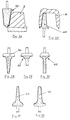
- tools of various types can be used. It may especially be strawberries 164, 166, 167, 168 ( Figures 26, 28, 29 and 30) for cutting teeth.
- tools corresponding to profile 165, 169, 170 can also be used on the machine which is the subject of the invention.
- strainers such as strainers, spa positioners: - tials, feelers, or others.
- FIG. 21 there are shown certain examples of specific clamping vices for the orthodontic arches and springs for the bending, forming and twisting end 86 of the machining unit 81 (FIG. 10 ).
- the element 121 is an eye, in which the arc 122 can be slid, which is subjected to the gauge vise 123 a bending stress in the direction of the arrow 124.
- the element 125 represents a calibrated vise in the form of gutter and folding corner 126.
- the element 127 is a ring eye of circular shape, in which the spring to be formed slides.
- Element 128 represents a caliber vice in a half-moon gutter, for folding in the direction of arrow 124.
- the elements in single gutter 129 and 130 represent an interlocking-folding assembly with interactive keying 131, 132, preventing skidding.
- Elements 133 and 134 also represent me a folding vice in gutter and corner, with keying between 135 and 136.
- Elements 137 and 138 represent a twist vice assembly particularly suitable for angular arcs.
- FIG. 22 represents a tool end 86 of the machining unit 81 (FIG. 10) allowing the automatic control of the clamping, folding, stamping and twisting vices 121, 123; 125, 127, 128, 129 - 130, 133-134, 137 - 138 ( Figure 21).
- the vice 145 can be moved in three dimensions of the space relative to a fixed vice 146, by virtue of the movements represented by the arrows 53, 147, 148, 149, 150, 151, 152, with respect to a fixed base 153.
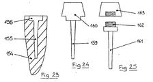
- a central channel 155 is cut in a root 154, provided with an upper shoulder 158, to accommodate a pivot 159 therein, supporting an artificial stump 160 similar to the natural stump 9 previously described.
- the dental surgeon first implements a pivot 161 provided with a threaded head 162, then he screws an artificial stump 163 onto the latter.
- One of the advantages of the present invention is to eliminate any risk of error during palpation performed in the mouth. Indeed, as recalled in the preamble, the known devices provide for using a feeler of which we only know that its end bears on the teeth already cut, while we can in no way guarantee whether its contact with the tooth takes place only at a point, or along a complete contact edge. This drawback is at the source of the numerous faults observed on known devices.
- this defect is automatically eliminated, given that the feeler consists of the surgical apparatus itself, the cutting edge of which, by definition, is in contact over its entire length with the trimmed part of the tooth.
Abstract
Description
- La présente invention est relative à un procédé et à un dispositif susceptibles d'être utilisés par un chirurgien-dentiste ou par un prothésiste dentaire, pour tailler, tâter, et enregistrer les valeurs topographiques cartésiennes des dents, des prothèses dentaires, tissus gingivaux et osseux, et des accessoires thérapeutiques, orthodontiques ou parodontaux qui y sont fixés.
- On sait qu'un chirurgien-dentiste est fréquemment amené à effectuer dans la bouche de son patient, diverses opérations consistant à tailler, mouler, ou abraser les dents. Le chirurgien-dentiste pratique de la sorte, notamment pour des constructions thérapeutiques odontologiques (obturations dentaires réalisées à l'aide d'amalgame, d'or, de résine, de céramique ou autre matériau), pour des constructions thérapeutiques chirurgicales (mise en place d'implants sous périoste, et attel_ .les ou intra-osseux, etc...), pour des constructions orthodontiques ou thérapeutiques parodontales (mise en place d'appareils métalliques ou autres, visant à corriger la position des dents), ainsi que pour la construction de prothèses restauratrices (couronnes, bridges, inlay, onlay, etc...) ou de prothèses amovibles (dentiers, prothèses à appui muqueux ou à insertions corono-muqueuses, etc.)
- L'invention concerne également la fabrication par un prothésiste, des constructions prothétiques ou orthopédiques correspondantes venant d'être mentionnées.
- Selon les procédés connus à ce jour, les constructions prothétiques ou thérapeutiques sont usinées à main levée. On commence généralement par réaliser, dans la bouche du patient, une empreinte du ou des organes à appareiller. De cette empreinte, on tire, par moulage, un modèle positif. Sur ce modèle positif, sont réalisés les accessoires ou la construction, soit directement par adaptation, soit indirectement, à l'aide d'une maquette en cire. Cette maquette permet de réaliser un moule dans lequel, par le procède du moulage à cire perdue, le prothésiste fabrique la construction définitive. Toutes ces opérations font ap nrnître un certain nombre de causes d'erreurs, dont on doit s'accommoder plus ou moins bien.
- Ainsi, il est demandé aux techniciens de laboratoires, lune competence de haut niveau lors de la réalisation de la maquette en cire, notamment pour juger si l'épaisseur de cire sera suffisante pour supporter les efforts développés en utilisation lors de la mastication.
- Le brevet Européen 0033.492 décrit une technique pour tâter le contour des moignons dentaires d'un modèle en plâtre, afin de recueillir des données qui sont enregistrées. Cela permet au prothésiste d'affiner les formes et dimensions de la prothèse qu'il usine à l'aide d'une machine-outil automatique. Dans ce but, il est nécessaire d'ajouter aux valeurs des données lues sur le moignon en plâtre, des corrections correspondant à l'épaisseur des parois, sans pour cela surdi- mensionner la prothèse.
- Suivant une autre technique connue par le brevet d'ALLEMAGNE FEDERALE 1 766 012, on réalise un modèle en plâtre, tout de suite après l'empreinte. La dent à couronner est préparée sur le modèle en plâtre, où l'on taille un moignon, dont l'épaulement gingival est travaillé avec beaucoup de précision. On prévoit par ailleurs un guide de fraisage qui permet de tailler en bouche, suivant un profil correspondant à celui du modèle de plâtre, le moignon de la dent à couronner, On constate qu'une telle technique ne permet pas d'assurer, notamment pour l'épaulement gingival, une précision d'exécution suffisante.
- Le brevet USA 4 182 312 décrit une technique pour la réalisation d'une prothèse amovible. Dans ce cas, on tâte les arcades dentaires supérieures et inférieures ainsi que les tissus gingivaux. Cela permet d'enregistrer des valeurs numériques à l'aide desquelles on commande une machine automatique pour la fabrication de la prothèse. La collecte de ces données nécessite l'emploi d'une installation dont le bras de guidage est relié à un doigt de tâtage, tout en comportant trois dispositifs pour le codage des valeurs mesurées dans les trois dimensions. Si l'on veut que les voleurs relevées avec un tel dispositif soient significatives, il faut effectuer un tâtage en des points très nombreux. De plus, l'absence d'un palpeur de pression mécanique nuit à la qualité des valeurs mesurées.
- Le brevet U.S.Adécrit une technique pour la mise en place d'un insert ou inlay dans une dent du patient. Le chirurgien-dentiste taille à main levée une cavit dans la dent de son patient. Cette cavité est ensuite photographiée, mesurée et codée, De'ces valeurs codées sont dérivées des données servant à la commande d'une machine : la dent taillée est remplie de cire, modelée en bouche en rapport avec la surface occlusale originelle. Ensuite, on enregistre en bouche cette surface occlusale modelée en cire ; pour cela, on utilise des moyens opto-électroniques. Les valeurs ainsi enregistrées sont utilisées pour commander une machine-outil qui réalise automatiquement l'inlay.
- On voit que, parmi ces procédés connus, aucun ne permet d'effectuer automatiquement l'ensemble des opérations. Dans tous les cas, une place importante est laissée au tour de main, si bien que subsiste une possibilité d'erreurs.
- La présente invention a pour but d'éviter ces inconvénients en réalisant un dispositif dont la mise en oeuvre soit facile pour le chirurgien-dentiste, tout en éliminant au maximum les risques d'erreurs.
- Un appareil selon l'invention comprend une tête porte-instrument sur laquelle est fixé l'instrument rotatif abrasif "turbine à air", que le chirurgien-dentiste présente dans la bouche de son patient, et il est caractérisé en ce que l'instrument rotatif est pourvu de moyens détecteurs fournissant des signaux caractéristiques à la fois des déplacements de l'outil et des efforts résistants qu' il rencontre, ces signaux étant enregistrés sur une machine calculatrice à mémoire, susceptible par la suite d'être utilisée pour commander automatiquement une machine-outil, si bien que le palpage du contour des surfaces dentaires est assuré par l'outil chirurgical lui-même.
- Suivant une autre caractéristique de l'invention, l'appareil comporte, par ailleurs, d'une part, des moyens optico- électroniques et ultra-soniques, pour tâter et enregistrer le contour des surfaces gingivales et dentaires, notamment en ce qui concerne lcs surfaces dentaires occlusalcs non préparées adjacentes et antagonistes et, d'autre part, des piges calibrées pour tâter αt repérer topographiquement les accessoires qui y sont fixés.
- Le dessin annexe, donné à titre d'exemple non limitatif, permettra de mieux cmprendre les caracteristique de l'invention.
-
- Figure 1 est une vue en coupe longitudinale d'une dent à soigner.
- Figure 2 est une coupe analogue après le taillage d'un moignon.
- Figure 3 montre une prothèse constituée par une couronne à appliquer sur le moignon de la figure 2.
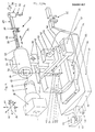
- Figure 4 est une vue d'ensemble contrant schématiquement un appareil selon l'invention.
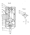
- Figure 5 en est une vue partielle avec coupe éclatée, montrant le détail du porte-outil.
- Fig. 6 schématise la détection des efforts transversaux.
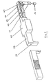
- Figures 7,8, et 9, montrent trois autres variantes de réalisation possibles, pour le montage du porte-outil qui constitue par ailleurs un capteur d'efforts.
- Figure 10 est un schéma-bloc illustrant le fonctionnement de l'appareil selon l'invention.
- Figures 11 et 12 montrent deux phases successives pour la fabrication d'une couronne dentaire selon l'invention.
- Figure 13 montre une autre variante selon l'invention, pour fabriquer une couronne dentaire.
- Figure 14 montre un étau d'asserrage automatique, qui, avec ses différentes articulations et directions de positionnement est utilisé lors de la fabrication d'une construction thérapeutique du type précité.
- Figure 15 montre les repères calibrés prévus sur le manche d'un porte-empreinte repéré d'un type connu, permettant l'enregistrement cartésien spatial des maxillaires.
- Figures 16, 17, et 18 montrent les autres embouts instrumentaux permettant tâtage et sondage, susceptibles d'être montés à la place de l'instrument rotatif 16.
- Figures 19 et 20 montrent respectivement le positionnement automatique, mécanique, de deux modèles en plâtre après repérage topographique selon l'invention, et la mise en articulation fonctionnelle de ces modèles.
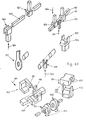
- Figure 21 représente plusieurs exemples d'étaux d'asserrage spécifiques à diverses opérations pour la fabrication des prothèses.
- Figure 22 illustre le détail d'une extrémité-outil pour l'unité d'usinage de la figure 10.
- Figure 23 montre, en coupe, une racine de dent préparée selon l'invention.
- Figure 24 montre un moignon à pivot destiné à être implanté dans la racine de la figure 27.
- Figure 25 est une vue analogue dans le cas d'un pivot à via.
- Figure 26 montre un outil chirurgical en train de tailler un moignon, selon l'invention.
- Figure 27 montre l'outil d'usinage correspondant, en train d'usiner la prothèse prévue pour le. moignon de la figure 20.
- Figures 28 à 30 illustrent plusieurs variantes de fraises chirurgicales selon l'invention.
- Figures 31 et 32 montrent plusieurs variantes correspondantes d'outils pour usiner les prothèses.
- Figures 33 à 35 illustrent une variante du même appareil porte-instrument asservi à distance par un système de commande à câble.
- On a représenté sur la figure 1, une dent 1, dont le volume est défini par une surface occlusale 2, et des faces latérales 3. A sa base, la dent 1 est entourée par la jonction dento-gingivale 4. La couche superficielle est constituée par de l'émail 15, coiffant la dentine ou ivoire 6. Les racines de la dent sont implantées dans le desmon- donte 7, dont la partie supérieure, ou parodonte, assure la liaison avec la gencive, au niveau de la jonction dento-gingivale 4.
- La ligne 8, dessinée en traits interrompus, représente généralement le niveau sous-gingival de l'épaulement dento- prothétique.
- Pour soigner et couronner cette dent, le dentiste taille un moignon coronnaire 9 (figure 2), qu'il coiffe ensuite à l'aide d'une couronne 10 en métal, en un matériau céramique ou autre.
- La présente invention concerne à la fois la taille du moignon 9, et la fabrication de la couronne 10, par usinage de sa matière. En particulier, on voit que la fabrication de la couronne 10 conduit le prothésiste à définir :
- - le profil extérieur de la couronne 10, correspondant
- à la conformation de la surface occlusale 2, et de la surface 12.
- -le profil intérieur 11 destiné à épouser le galbe du moignon 9 ;
- -le tracé exact de l'épaulement périphérique inférieur 13, destiné à venir s'adapter avec précision sur l'épaulement gingival 4 que le chirurgien dentiste a taillé autour de la base du moignon 9.
- Selon l'invention, et grâce à un appareil 15 (figure 4), le chirurgien-dentiste taille le moignon 9 et l'épaulement 14 de la dent 2 en utilisant un instrument rotatif 17 portant une meulette-fraise abrasive 16 qui peut être de tout type connu, ou bien correspondre aux meulettes illustrées sur les figures 26, 29, ou 30.
- Par contre, pour usiner, par exemple, la couronne 10, le prothésiste utilise des fraises rotatives du genre de celles qui apparaissent sur les figures 27, 31, ou 32.
- Pour effectuer ces opérations, la présente invention prévoit de réaliser un appareil 15, du genre illustré sur la figure 4. A cet effet, la meulette-fraise abrasive 16 est montée dans l'instrument rotatif 17 (figures 4, 5, 6, 7, 9), pour lequel l'invention prévoit plusieurs variantes possibles de montage.
- La meulette-fraise 16 est entraînée en rotation par son axel8 inséré dans l'arbre 19 du rotor 20. Ce dernier peut être constitué, par exemple, par un rotor de turbine à air de type connu. (figure 5).
- Selon l'invention, l'arbre 19 du rotor 20 comporte au moins deux aimants permanents 21 et 22, décalés angulairement, et situés chacun au niveau de l'un des deux paliers fixes 23 et 24 de l'instrument rotatif 17. Dans chacun des paliers 23 et 24, sont logés des capteurs inductifs de proximité, ou de champ magnétique à effet Hall, du genre désigné sur la figure 6, par la référence 25. Cette figure correspond au palier 23, à l'intérieur duquel tourne l'aimant 21, mais il est bien évident qu'une disposition analogue est prévue pour le palier 24 Et son aimant 22. L'aimant 21 est préférablement décalé angulairement de 90 °, par rapport a l'aimant 22.
- Quand l'arbre 19 tourne pendant que le chirurgien-dentiste maintient en bouche l'outil 17, ce dernier est soumis, de la part de la dent 1 qu'il usine , à des réactions transversales dont l'orientation et l'intensité sont détectées et mesurées par les micro-déplacements transversaux qui en résultent pour les aimants 21 et 22, par rapport aux capteurs de proximité inductifs ou/et à effet Hall, inclus dans les paliers 23 et 24.
- Dans une autre variante où le rotor tourne dans un palier à air , le rotor lui-même constitue l'aimant permanent inducteur; les capteurs de proximité inductifs, ou bien de champ magnétique à effet Hall 26,sont répartis autour du rotor.Les paliers 23 et 24 peuvent être construits à l'intérieur même du rotor 20,ce qui permet d'en réduire l'encombrement.
- Grâce à cette disposition, on voit que l'instrument rotatif 17 portant la fraise 16 assure, selon l'invention, au moins deux fonctions simultanées , à savoir
- - d'une part , grâce à cette fraise 16 , l'instrument rotatif 17 usine la dent 1 pour tailler le moignon 9 et l'épaulement 14 ;
- - d'autre part,et simultanément,l'instrument rotatif joue le rôle d'un palpeur fournissant en permanence des données numériques caractéristiques du profil usiné sur le moignon 9 et sur l'épaulement 14.
- L'appareil illustré sur les fig. 4 à 8 permet de capter ces informations numériques et de les stocker en mémoire, pour les restituer ensuite à l'outil d'usinage, lorsque de- lui-ci sera utilisé pour tailler la couronne 10 (figures 11 à 13, 27 , 31 et 32).
- Dans la variante illustrée sur la fig. 4, l'instrument rotatif 17 est solidarisé du bras 29 par un accouplement démontable 27. Ce bras télescopique 29, muni en son extrémité d' une crémaillère 30,traverse axialement l'arbre 31. Ce dernier est équipé d'un moteur pas à pas 32 qui commande, par un pignon ici non représenté, le bras télescopique 29, au niveau de sa crémaillère 30. Ce bras télescopique 29 peut,en réponse à la commande du moteur pas à pas, coulisser selon son axe longitudinal 33 (flèche double 34).Par ailleurs, l'arbre 31,porteur du bras 29,est agrémenté d'une couronne dentée 35.I1 s'insère dans le palier36,qui porte un moteur pas à pas 37.
- Grâce à un pignon ici non représenté,ce dernier , par action au niveau de la couronne dentée 35, commande le pivotement du bras 29 autour de son axe longitudinal (flèche 38), muni d'une crémaillère 25.
- En lieu et place de l'instrument rotatif 17, peut être montée au niveau de l'accouplement démontable 27 de la tête porte-outil, une extrémité-pige calibrée de tâtage 110, 111, 112 (figure 16). En lieu et place de 17 et 110, 111, 112, on peut aussi monter un système de capteur opto-électronique 113 (figure 17).
- En lieu et place de 110, 111, 112, 113, on peut encore monter un système d'émetteur et de capteurs ultra-soniques 114 (figure 18).
- Après assemblage, l'unité qui vient d'être décrite est portée par le palier 36 dont le pied 39 est articulé sur un axe 40 qui, commandé par un moteur pas à pas 41, peut basculer par rapport au palier 42 dans le sens de la flèche double 43. Le palier porteur 42 est fixé à un chariot 44. Ce dernier est soumis à l'action d'un moteur pas à pas 45 qui commande son coulissement par rapport à une platine de support 46. Ce coulissement est effectué suivant une direction 47, schématisée par la flèche double 48, perpendiculairement à l'axe longitudinal théorique 33 du bras télescopique 29.
- La platine 46 est portée par une colonne élévatrice 49 susceptible d'être soulevée ou abaissée, comme indiqué par la flèche double 50, en réponse à une commande pas à pas 51.
- Parallèlement à la direction de l'axe théorique 52, le socle 53 fixé à une roue dentée 54 peut pivoter par rapport à l'axe théorique 52 dans le sens de la flèche double circulaire 56, en réponse à la commande d'un moteur pas à pas 55 solidarisé du socle 57.
- Les dispositifs de commande pas à pas 32, 37, 41, 45, 51, 56, groupent chacun un convertisseur de données angulaires de type connu. Chacun de ces dispositifs permet de coder et de décoder les informations détectées, ce qui permet de transformer tout mouvement dans l'une ou l'autre des trois dimensions schématisées par les directions 33, 47, 52, pour engendrer des signaux logiques, et vice versa.
- Le socle fixe 57 portant tout l'appareil porte-instrument décrit ci-dessus est équipé d'un pied de fixation 58, et muni d'un accouplement démontable 59 , solidarisable des immobilisateurs maxillaires d'un quelconque type connu.
- Ce socle 57 est équipé d'une unité pour la télécommande des mécanismes d'asservissement , ici représentée par un pupitre 60 . Ce pupitre peut comporter notamment deux leviers de commande 61 et 62.
- dans la variante illustrée sur la figure 7 le bras télescopique 29 se termine par une fourche 63 portant un axe d'extrémité transversal 64 . Sur ce dernier , est articulée la tête circulaire dentée 65 , de l'instrument rotatif 17 . Une vis sans fin 66 engrène sur la tête circulaire dentée 65 qui forme un pignon commandant l'orientation de l'instrument rotatif 17 autour de l'axe 64 . Cette orientation est définie par une commande pas à pas 67 agissant sur la position angulaire de la vis sans fin 66.
- Dans la variante illustrée sur la figure 8, le basculement du porte-outil 17 autour de l'axe 64 porté par la fourchette 63 s'effectue en réponse aux déplacements longitudinaux ( flèche 34) d'une tige 68 ayant une extrémité articulée en 69 sur le sommet du porte-outil 17 ,alors que son extrémité opposée comporte une crémaillère 70 qu' actionne un pignon 71 .
- Dans la variante illustrée sur la figure 9 ; la tige 72 de la fourche 63 est mobile en basculement autour de deux axes orthogonaux , grâce à une articulation de Cardan 73 logée dans le bras 29.
- Le mouvement à deux degrés de liberté au niveau de l'extrémité libre de la tige 72 permet d'enregistrer les contraintes de fraisage et de tâtage de l'instrument rotatif 17 . Au niveau de cette extrémité libre , sont montés des sensors de pression mécanique ( en allemand : " Druck- messdosen") . De même , au niveau de la tige 68 et de la tige 72 , sont montés des sensors de pression mécanique 75 et 76 , permettant d'enregistrer les contraintes dans le troisième degré de liberté .Le mouvement à deux degrés de liberté qui en résulte est commandé , comme précédemment ,par une tige coulissante 50 . Un troisième degré de liberté peut être défini dans la direction de la flèche 77 .
- Le fonctionnement est le suivant :
- Quand le dentiste travaille sur la dent 1 , avec son instrumènt rotatif 17 ( figure 10) , ou un autre embout instrumental accouplé à l'appareil 15 représenté par la figure 4 , l'unité de visualisation électronique 78 de l'appareil , permet d'émettre des signaux numériques de tâtage , qui sont traités dans un système cde commande 79 , puis stockés dans une mémoire 80.
- Ensuite , en utilisant une unité d'usinage à forme de machine-outil 81 , le prothésiste peut :
- - en utilisant des fraises de type connu.pou de forme spéciale 162 à 170 , fabriquer une couronne dentaire ;
- - en utilisant l'extrémité d'usinage 82 , tailler les différentes faces 2 , 12 , 13 , d'uner couronne 10 ;
- - en utilisant l'extrémité d'usinage 83 , tailler un modèle 84 ( reproduisant par exemple , le moignon 9) ;
- - en utilisant l'extrémité d'usinage 85 , retoucher et corriger des duplicata de moulage 86 ( tels que les modèles d'arcades 115 , 116 , - figures 19 et 20).
- Pour ces différentes phases , le prothésiste peut utiliser un étau d'immobilisation 90 ( figure 14) ,à positionnement spatial automatisé .
- En utilisant des extrémités d'usinage du genre des étaux de contrainte ,il peut réaliser , par pliage , formage , emboutissage et vrillage , les accessoires à fixer définitivement ou temporairement aux dents et tissus ( tels que crochets de prothèsé , arcs et ressorts orthodontiques).
- Grâce à une extrémité de tâtage 87 ,équipant une installation 88 , connectée en parallèle de l'unité d' usinage 81 , l'utilisateur effectue un tâtage , soit de la construction prothétique ou thérapeutique 10 , soit du modèle 84 , soit du duplicata 86 ( figure 10-). La machine compare les valeurs ainsi lues par l'intermédiaire de la mémoire 89 , reliée à cet effet à la mémoire 80.
- .Les valeurs cartésiennes ainsi traitées et mémorisées servent éventuellement à modifier les valeurs cartésiennes buccales de la mémoire 79 , ou les valeurs d'asservissement de l'appareil 15 , en modification des données cartésiennes initiales de l'intervention buccale , comme par exemple pour une équilibration buccale.
- On a illustré sur les figures 11 et 12 un exemple pour l'usinage d'une couronne 10 , à partir d'une pièce brute , ou déjà préformée . Unb étau 90 , du type illustré sur la figure 14 , maintient en place cette ébauche 91 . Plus particulièrement , il maintient en place la partie inférieure sde la pièce , pendant qu'on usine sa partie supérieure (figure 11) et vice versa ( figure 12).
- Sur la figure 13 , on a illustré une autre possibilité , dans laquelle l'usinage est effectué pour toutes les faces de la couronne 10 , à l'intérieur et à l'extérieur , excepté à l'endroit prévu comme pieds de fixation 92 , qui est enserré par l'étau 90 . Ce raccordement de fixation est éliminé en fin d'opération .
- Sur la figure 14 , est schématisé l'étau 90 , qui permet un positionnement spatial de la construction prothétique ou thérapeutique dans les trois directions de l'espace 93 grâce à un ensemble d'unités d'asservissement automatique 94 , 95 , 96 , 97 , 98 , 99 , 100 , qui permettent les déplacements dans chacune des directions fléchées 101 , 102 , 103 , 104 , 105 , 106 , 107 .
- Sur la figure 15 , on a montré la position spatiale des repères 108 réalisés sur le manche d'un quelconque porte-empreinte connu 109 . Grâce à l'embout instrumental 110 , ou à une de ses variantes 111 , 112 (figure 16) , ces repères calibrés sont localisés cartésiennement par rapport aux tissus dentaires et gingivaux subissant cette empreinte . Ces tissus gingivaux et dentaires voisins et antagonistes sains nnon traités chirur gicalement, sont eux-mêmes tâtés,soit opto-électroniquement par l'embout 113 (figure 17) , soit par l'embout ultrasonique 114 (figure 18).
- Sur les modèles en plâtre 115 et 116 (figure 19) tirés de cette empreinte , les repères 108 sont mécaniquement reportés par l'otuil d'usinage 85 (figure 10) ,en des repères 117 , permettant ainsi la localisation des modèles en plâtre et de leurs accessoires , par rapport aux repères initiaux 108 .
- Sur la figure 19 , l'interpositionnement spatial correct des deux modèles 115 et 116 correspondant aux arcades de la denture est réalisé par l'interpositionnement spatial des repères 117 qu'on y a rapportés . Ce réglage est mené à bien par les extrémités de positionnement automatique 118 et 119 ( figure 19) de l'unité d'usinage 81 (figure 10) tâté en permanence pour cela par une extrémité de tâtage 110 ( figure 16) de l'installation de tâtage 88 ( figure 10) .
- Sur la figure 20 , les positionneurs automatiques 118 et 119 , montés sur un quelconque articulateur 120 , permettent l'interpositionnement dynamique d'étude.et de travail classique , conformément à la morphologie des mâchoires du patient .
- Bien entendu , pour toutes ces opérations , on peut utiliser des outils de types divers . Il peut s'agir notamment de fraises 164 , 166 , 167 , 168 ( figures 26 ,28, 29 et 30) pour tailler les dents.
- Dans la phase de fabrication de la prothèse, des outils correspondant au profil 165 , 169 , 170 (figures 27 , 31 et 32) sont également utilisables sur la machine objet de l'invention .
- De plus , on peut utiliser différentss accessoires telsd que des étaux de contrainte , positionneurs spa:- tiaux , tâteurs , ou autres .
- Ainsi , sur la figure 21 , on a représenté certains exemples d'étaux d'asserrage spécifiques pour les arcs et ressorts d'orthodontie pour l'extrémité de pliage , formage et vrillage 86 de l'unité.d'usinage 81 ( figurre 10). L'élément 121 est un chas , dans lequel peut être glissé 1' arc 122 , qui subit de l'étau-calibre 123 une contrainte de pliage dans le sens de la flèche 124 .L'élément 125 représente un étau calibré à forme de gouttière et coin de pliage 126 . L'élément 127 est un chas d'asserrage à forme circulaire , dans lequel coulisse le ressort à former.
- L'élément 128 représente un étau-calibre en gouttière demi-lune , pour pliage dans le sens de la flèche 124 .
- Les éléments en gouttière simple 129 et 130 représentent un ensemble asserrage-pliage à clavetage interactif 131 , 132 , évitant le dérapage.
- Les éléments 133 et 134 représentent de même un étau de pliage en gouttière et coin , avec clavetage entre 135 et 136.
- Les éléments 137 et 138 représentent un ensemble étau de vrillage particulièrement indiqué pour les arcs anguleux .
- La figure 22 représente une extrémité outil 86 de l'unité d'usinage 81 ( figure 10) permettant l'asservissement automatique des étaux d'asserrage , pliage , emboutissage et vrillage 121 , 123 ; 125 , 127 , 128 , 129 - 130 , 133-134 , 137 - 138 (figure 21) .
- En utilisant chacune des unités d'asservissement 139 , 140 , 141 , 142 , 143 , 144 , l'étau 145 peut être déplacé dans les trois dimensions de l'espace par rapport à un étau fixe 146 , grâce aux mouvements représentés par les flèches 53 , 147 , 148 , 149 , 150 , 151 , 152 , par rapport à un socle fixe 153.
- Dans l'exemple illustré sur les figures 23 à 25 , on taille , dans une racine 154 , un canal central 155 , muni d'un épaulement supérieur 158 , pour y loger un pivot 159 , supportant un moignon artificiel 160 analogue au moignon naturel 9 précédemment décrit .
- Dans la variante illustrée sur la figure 25, le chirurgien-dentiste implante tout d'abord un pivot 161 muni d'une tête filetée 162 , puis il visse sur cette dernière , un moignon artificiel 163 .
- L'un des avantages de la présente invention est de supprimer tout risque d'erreur , lors du palpage effectué en bouche . En effet , comme rappelé dans le préam- b ule , les dispositifs connus prévoient d'utiliser un palpeur dont on sait seulement que son extrémité porte appui sur les dents déjà taillées , alors qu'on ne peut nullement garantir si son contact avec la dent s'effectue seulement en un point , ou bien le long d'une complète arête de contact .Cet inconvénient est à la source des nombreux défauts observés sur les appareils connus.
- Dans l'invention ce défaut est automatiquement éliminé , étant donné que le palpeur est constitué par l' appareil chirurgical lui-même , dont , par définition , l' arête coupante est en contact sur toute sa longueur avec la partie taillée de la dent .
- Enfin , on voit que le dispositif selon l'invention permet après tâtage initial des surfaces dentaires occlusales et latérales non encore préparées :
- - de déterminer les formes et contours des abrasions, fraisage , et meulage à effectuer ;
- - de déterminér l'épaisseur idéale minima à abraser en fonction des données mécaniques propres des matériaux employés dans la construction , en réduisant la mutilation tissulaire au minimum ; .
- - de déterminer les axes anatomiques propres de chaque dent
- - de déterminer les axes interactifs et l'axe idéal de taille pour une dent ou plusieurs dents entre elles ,et l'axe d'insertion idéal de la prothèse ;
- - puis de réaliser une taille tissulaire aussi précise que possible en automatisme complet ou à des degrés variables ;
- - du fait de l'enregistrement en continu des déplacements de l'instrument intra-buccal : rotatif , capteur, tâteur ,pige calibrée d'avoir tous les relevés topographiques en continu ;
- - par l'utilisation des autres embouts instrumentaux, de repérer et positionner les accessoires fixes définitifs ou temporaires au niveau des dents et tissus ;
- - par repérage et positionnement de repères calibrés sur les exrémités extra-buccales des fixateurs maxillaires, d'enregistrer l'inter-relation spatiale de ces repères aux autres tissus dentaires et gingivaux , d'enregistrer dynamiquement les interactions spatiales des deux maxillaires 1' un à l' autre.
Claims (31)
Applications Claiming Priority (3)
| Application Number | Priority Date | Filing Date | Title |
|---|---|---|---|
| DE3203937 | 1982-02-05 | ||
| DE3203937A DE3203937C2 (de) | 1982-02-05 | 1982-02-05 | Verfahren und Vorrichtung zum maschinellen Sanieren oder Korrigieren mindestens eines Zahnes oder zum maschinellen Vorbereiten mindestens eines Zahnes für eine festsitzende prothetische Restaurierung und zum maschinellen Herstellen der festsitzenden prothetischen Restaurierung |
| ES520981A ES8402714A1 (es) | 1982-02-05 | 1983-03-25 | Aparato para tallar y cuidar los dientes y las protesis dentarias. |
Publications (2)
| Publication Number | Publication Date |
|---|---|
| EP0086167A2 true EP0086167A2 (fr) | 1983-08-17 |
| EP0086167A3 EP0086167A3 (fr) | 1984-01-18 |
Family
ID=42224212
Family Applications (1)
| Application Number | Title | Priority Date | Filing Date |
|---|---|---|---|
| EP83420021A Ceased EP0086167A3 (fr) | 1982-02-05 | 1983-02-03 | Procédé et dispositif pour tailler ou soigner des dents ou des prothèses dentaires |
Country Status (4)
| Country | Link |
|---|---|
| US (1) | US4478580A (fr) |
| EP (1) | EP0086167A3 (fr) |
| DE (1) | DE3203937C2 (fr) |
| ES (1) | ES8402714A1 (fr) |
Cited By (9)
| Publication number | Priority date | Publication date | Assignee | Title |
|---|---|---|---|---|
| EP0160797A1 (fr) * | 1984-03-06 | 1985-11-13 | Werner H. Dr.med.dent. Mörmann | Ebauche pour la fabrication de pièces façonnées en technique dentaire et utilisation de celle-ci |
| FR2582932A1 (fr) * | 1985-06-07 | 1986-12-12 | Deoux Georges | Dispositif pour la fabrication de protheses dentaires adjointes completes obtenues a partir de preformes bases et de preformes arcades |
| FR2627077A1 (fr) * | 1988-02-17 | 1989-08-18 | Waysenson Bernard | Articulateur dentaire |
| EP0345975A2 (fr) * | 1988-06-09 | 1989-12-13 | William Loran | Appareil pour travaux dentaires indirects |
| EP0423615A1 (fr) * | 1989-10-18 | 1991-04-24 | Degussa Ag | Dispositif et procédé pour la fabrication de couronnes internes dentaires |
| EP0503890A2 (fr) * | 1991-03-12 | 1992-09-16 | Yuusuke Nonomura | Dispositif et méthode pour la fabrication de produits d'obturation dentaire destiné à la réparation de couronnes dentaires |
| EP0565175A2 (fr) * | 1992-04-06 | 1993-10-13 | Elephant Holding B.V. | Prothèse dentaire et procédé de fabrication |
| WO2012068667A1 (fr) * | 2010-11-22 | 2012-05-31 | Biocad Medical Inc. | Procédé et dispositif utilisables en vue de la fabrication d'un composant dentaire |
| CN104958118A (zh) * | 2015-07-20 | 2015-10-07 | 武汉大学 | 一种用于牙齿开髓牙体预备的智能机器人 |
Families Citing this family (275)
| Publication number | Priority date | Publication date | Assignee | Title |
|---|---|---|---|---|
| SE448598B (sv) * | 1984-01-26 | 1987-03-09 | Procera Dental Ab | Forfarande och anordning for att ersetta forlorad tandsubstans |
| DE3415006A1 (de) * | 1984-04-19 | 1985-11-07 | Helge Dr. 8000 München Fischer-Brandies | Zahntechnisches verfahren und vorrichtung zum biegen und tordieren eines drahtstueckes |
| DE3442158A1 (de) * | 1984-11-17 | 1986-05-28 | Rudi 7080 Aalen Körner | Verfahren und vorrichtung zum fraesen von zahnersatz |
| DE3604531A1 (de) * | 1986-02-13 | 1987-08-20 | Kurt Kern Gmbh & Co Kg | Verfahren zur herstellung von zahnersatzteilen und vorrichtung zur durchfuehrung dieses verfahrens |
| SE465498B (sv) * | 1989-08-17 | 1991-09-23 | Anders Sundh | Metod foer framstaellning av restaurationer, proteser eller liknande inom tand- och sjukvaarden |
| US5545039A (en) * | 1990-04-10 | 1996-08-13 | Mushabac; David R. | Method and apparatus for preparing tooth or modifying dental restoration |
| US5569578A (en) * | 1990-04-10 | 1996-10-29 | Mushabac; David R. | Method and apparatus for effecting change in shape of pre-existing object |
| NL9200642A (nl) * | 1992-04-06 | 1993-11-01 | Elephant Holding Bv | Werkwijze voor het vervaardigen van een tandheelkundige prothese. |
| SE470346B (sv) * | 1992-06-23 | 1994-01-31 | Sandvik Ab | Metod för framställning av keramiska artificiella tandrestaurationer |
| US5453009A (en) * | 1993-12-29 | 1995-09-26 | Feldman; Yasha | Method of and system for dental treatment |
| DE4404695C2 (de) * | 1994-02-15 | 1998-11-19 | Dietmar Walter | Verfahren zum Herstellen orthopädischer Einlagen |
| DE4443929C1 (de) * | 1994-12-09 | 1996-02-01 | Volkmar Schmidt | Verfahren zur patientenspezifischen Herstellung von und Versorgung mit zahnprothetischen Werkstücken |
| US5846081A (en) * | 1995-08-23 | 1998-12-08 | Bushway; Geoffrey C. | Computerized instrument platform positioning system |
| US5688118A (en) * | 1995-12-27 | 1997-11-18 | Denx Ltd. | Image sound and feeling simulation system for dentistry |
| US6450807B1 (en) | 1997-06-20 | 2002-09-17 | Align Technology, Inc. | System and method for positioning teeth |
| AU744385B2 (en) * | 1997-06-20 | 2002-02-21 | Align Technology, Inc. | Method and system for incrementally moving teeth |
| US6705863B2 (en) | 1997-06-20 | 2004-03-16 | Align Technology, Inc. | Attachment devices and methods for a dental appliance |
| US5975893A (en) * | 1997-06-20 | 1999-11-02 | Align Technology, Inc. | Method and system for incrementally moving teeth |
| US6409504B1 (en) | 1997-06-20 | 2002-06-25 | Align Technology, Inc. | Manipulating a digital dentition model to form models of individual dentition components |
| US7247021B2 (en) | 1997-06-20 | 2007-07-24 | Align Technology, Inc. | Subdividing a digital dentition model |
| US7063532B1 (en) | 1997-06-20 | 2006-06-20 | Align Technology, Inc. | Subdividing a digital dentition model |
| US8496474B2 (en) | 1997-06-20 | 2013-07-30 | Align Technology, Inc. | Computer automated development of an orthodontic treatment plan and appliance |
| US6152731A (en) * | 1997-09-22 | 2000-11-28 | 3M Innovative Properties Company | Methods for use in dental articulation |
| IL122807A0 (en) | 1997-12-30 | 1998-08-16 | Cadent Ltd | Virtual orthodontic treatment |
| US9084653B2 (en) | 1998-01-14 | 2015-07-21 | Cadent, Ltd. | Methods for use in dental articulation |
| IL125659A (en) | 1998-08-05 | 2002-09-12 | Cadent Ltd | Method and device for three-dimensional simulation of a structure |
| US6514074B1 (en) | 1999-05-14 | 2003-02-04 | Align Technology, Inc. | Digitally modeling the deformation of gingival |
| US6802713B1 (en) * | 1998-10-08 | 2004-10-12 | Align Technology, Inc. | Defining tooth-moving appliances computationally |
| US11026768B2 (en) | 1998-10-08 | 2021-06-08 | Align Technology, Inc. | Dental appliance reinforcement |
| AR021854A1 (es) | 1998-10-08 | 2002-08-07 | Ali Amjad | Desarrollo automatizado por computadora de un plan y aparato de tratamiento ortodontico |
| US7121825B2 (en) * | 1998-11-30 | 2006-10-17 | Align Technology, Inc. | Tooth positioning appliances and systems |
| US6406292B1 (en) | 1999-05-13 | 2002-06-18 | Align Technology, Inc. | System for determining final position of teeth |
| JP3636662B2 (ja) | 1998-11-30 | 2005-04-06 | アライン テクノロジー, インコーポレイテッド | 歯の器具に関する装着デバイスおよび方法 |
| US7108508B2 (en) * | 1998-12-04 | 2006-09-19 | Align Technology, Inc. | Manipulable dental model system for fabrication of a dental appliance |
| WO2000033759A1 (fr) | 1998-12-04 | 2000-06-15 | Align Technology, Inc. | Modele dentaire reconfigurable pour la fabrication d'appareils orthodontiques |
| US6488499B1 (en) * | 2000-04-25 | 2002-12-03 | Align Technology, Inc. | Methods for correcting deviations in preplanned tooth rearrangements |
| US7357636B2 (en) * | 2002-02-28 | 2008-04-15 | Align Technology, Inc. | Manipulable dental model system for fabrication of a dental appliance |
| EP1150618A4 (fr) * | 1999-01-15 | 2002-10-16 | Align Technology Inc | Systeme et methode de deplacement d'une dent |
| US6099303A (en) * | 1999-02-01 | 2000-08-08 | University Of Florida | Force recording orthodontic appliance |
| EP1115338B1 (fr) * | 1999-05-07 | 2006-08-16 | Aesculap AG & Co. KG | Outil chirurgical a rotation |
| US6318994B1 (en) * | 1999-05-13 | 2001-11-20 | Align Technology, Inc | Tooth path treatment plan |
| US6602070B2 (en) * | 1999-05-13 | 2003-08-05 | Align Technology, Inc. | Systems and methods for dental treatment planning |
| US6633789B1 (en) * | 2000-02-17 | 2003-10-14 | Align Technology, Inc. | Effiicient data representation of teeth model |
| US7373286B2 (en) | 2000-02-17 | 2008-05-13 | Align Technology, Inc. | Efficient data representation of teeth model |
| US20020188478A1 (en) | 2000-03-24 | 2002-12-12 | Joe Breeland | Health-care systems and methods |
| US7904307B2 (en) | 2000-03-24 | 2011-03-08 | Align Technology, Inc. | Health-care e-commerce systems and methods |
| WO2001074268A1 (fr) * | 2000-03-30 | 2001-10-11 | Align Technology, Inc. | Systeme et procede de separation de modeles tridimensionnels |
| DE10017474B4 (de) * | 2000-04-07 | 2004-07-08 | Degudent Gmbh | Zahntechnisches Fräsgerät |
| WO2001082192A1 (fr) | 2000-04-25 | 2001-11-01 | Align Technology, Inc. | Systeme et procede d'analyse en vue de traitements |
| US6582229B1 (en) * | 2000-04-25 | 2003-06-24 | Align Technology, Inc. | Methods for modeling bite registration |
| US6454565B2 (en) | 2000-04-25 | 2002-09-24 | Align Technology, Inc. | Systems and methods for varying elastic modulus appliances |
| US6947038B1 (en) | 2000-04-27 | 2005-09-20 | Align Technology, Inc. | Systems and methods for generating an appliance with tie points |
| US6832877B2 (en) * | 2000-05-29 | 2004-12-21 | Kabushiki Kaisya Advance | Dental measuring and machining system |
| US7245977B1 (en) | 2000-07-20 | 2007-07-17 | Align Technology, Inc. | Systems and methods for mass customization |
| US7383198B1 (en) | 2000-07-24 | 2008-06-03 | Align Technology, Inc. | Delivery information systems and methods |
| US7092784B1 (en) | 2000-07-28 | 2006-08-15 | Align Technology | Systems and methods for forming an object |
| US7040896B2 (en) | 2000-08-16 | 2006-05-09 | Align Technology, Inc. | Systems and methods for removing gingiva from computer tooth models |
| US6482284B1 (en) | 2000-08-31 | 2002-11-19 | 3M Innovative Properties Company | Method of making a dental mill blank and support stub assembly |
| US6497574B1 (en) * | 2000-09-08 | 2002-12-24 | Align Technology, Inc. | Modified tooth positioning appliances and methods and systems for their manufacture |
| US6607382B1 (en) * | 2000-09-21 | 2003-08-19 | Align Technology, Inc. | Methods and systems for concurrent tooth repositioning and substance delivery |
| US7736147B2 (en) | 2000-10-30 | 2010-06-15 | Align Technology, Inc. | Systems and methods for bite-setting teeth models |
| AU2002218974A1 (en) * | 2000-11-08 | 2002-05-21 | Willytec Gmbh | (dental) surface mapping and generation |
| US6783360B2 (en) * | 2000-12-13 | 2004-08-31 | Align Technology, Inc. | Systems and methods for positioning teeth |
| US6669875B2 (en) | 2000-12-18 | 2003-12-30 | 3M Innovative Properties Company | Method for making a dental mill blank assembly |
| US7074038B1 (en) | 2000-12-29 | 2006-07-11 | Align Technology, Inc. | Methods and systems for treating teeth |
| CN100374089C (zh) * | 2001-07-13 | 2008-03-12 | 德固萨有限责任公司 | 由三维测定的数字化阳模制造假牙 |
| US7771195B2 (en) * | 2001-10-29 | 2010-08-10 | Align Technology, Inc. | Polar attachment devices and method for a dental appliance |
| US6767208B2 (en) | 2002-01-10 | 2004-07-27 | Align Technology, Inc. | System and method for positioning teeth |
| GB0201362D0 (en) * | 2002-01-22 | 2002-03-13 | Renishaw Plc | Reversible sample holder |
| US6830450B2 (en) | 2002-04-18 | 2004-12-14 | Align Technology, Inc. | Systems and methods for improved engagement between aligners and teeth |
| US20030207227A1 (en) * | 2002-05-02 | 2003-11-06 | Align Technology, Inc. | Systems and methods for treating patients |
| US7255558B2 (en) | 2002-06-18 | 2007-08-14 | Cadent, Ltd. | Dental imaging instrument having air stream auxiliary |
| US6979196B2 (en) * | 2002-06-21 | 2005-12-27 | Align Technology, Inc. | Systems and methods for automated bite-setting of tooth models |
| US20040243361A1 (en) * | 2002-08-19 | 2004-12-02 | Align Technology, Inc. | Systems and methods for providing mass customization |
| US7156661B2 (en) * | 2002-08-22 | 2007-01-02 | Align Technology, Inc. | Systems and methods for treatment analysis by teeth matching |
| US7077647B2 (en) * | 2002-08-22 | 2006-07-18 | Align Technology, Inc. | Systems and methods for treatment analysis by teeth matching |
| US20040152036A1 (en) * | 2002-09-10 | 2004-08-05 | Amir Abolfathi | Architecture for treating teeth |
| US20040197728A1 (en) * | 2002-09-10 | 2004-10-07 | Amir Abolfathi | Architecture for treating teeth |
| EP2465464B1 (fr) | 2002-10-03 | 2018-08-22 | Align Technology, Inc. | Procédé de préparation d'un modèle physique |
| US7029279B2 (en) * | 2002-10-07 | 2006-04-18 | Mark Schomann | Prosthodontia system |
| DE50308814D1 (de) * | 2002-10-18 | 2008-01-24 | Aepsilon Rechteverwaltungs Gmb | Vorrichtungen und verfahren zur oberflächenerfassung und zur herstellung von zahnersatzteilen |
| AU2003300135B2 (en) | 2002-12-31 | 2009-07-16 | D4D Technologies, Llc | Laser digitizer system for dental applications |
| DE10301643B4 (de) * | 2003-01-17 | 2008-02-14 | Ivoclar Vivadent Ag | Verfahren zur Herstellung eines Dentalproduktes, insbesondere einer dentalen Restauration, Dentalrestaurationsvorrichtung und Verfahren zur maschinellen Bearbeitung |
| US7658610B2 (en) * | 2003-02-26 | 2010-02-09 | Align Technology, Inc. | Systems and methods for fabricating a dental template with a 3-D object placement |
| US7600999B2 (en) * | 2003-02-26 | 2009-10-13 | Align Technology, Inc. | Systems and methods for fabricating a dental template |
| US20040166463A1 (en) * | 2003-02-26 | 2004-08-26 | Align Technology, Inc. | Systems and methods for combination treatments of dental patients |
| US20040166462A1 (en) | 2003-02-26 | 2004-08-26 | Align Technology, Inc. | Systems and methods for fabricating a dental template |
| CA2519075C (fr) | 2003-03-24 | 2008-11-18 | D3D, L.P. | Systeme numeriseur laser pour applications dentaires |
| WO2004087000A1 (fr) | 2003-04-03 | 2004-10-14 | Cadent Ltd. | Procede et systeme de fabrication d'une chape dentaire et chape dentaire ainsi fabriquee |
| WO2004100068A2 (fr) * | 2003-05-05 | 2004-11-18 | D3D, L.P. | Imagerie de tomographie par coherence optique |
| US7648360B2 (en) * | 2003-07-01 | 2010-01-19 | Align Technology, Inc. | Dental appliance sequence ordering system and method |
| US7030383B2 (en) | 2003-08-04 | 2006-04-18 | Cadent Ltd. | Speckle reduction method and apparatus |
| EP1506745A1 (fr) * | 2003-08-15 | 2005-02-16 | Jeanette Mörmann | Ebauche et procédé de fabrication d'une restauration dentaire |
| US7342668B2 (en) * | 2003-09-17 | 2008-03-11 | D4D Technologies, Llc | High speed multiple line three-dimensional digitalization |
| US7361020B2 (en) * | 2003-11-19 | 2008-04-22 | Align Technology, Inc. | Dental tray containing radiopaque materials |
| US7226338B2 (en) * | 2004-08-12 | 2007-06-05 | D4D Technologies, Llc | Milling machine |
| US20050182654A1 (en) * | 2004-02-14 | 2005-08-18 | Align Technology, Inc. | Systems and methods for providing treatment planning |
| US20050186524A1 (en) * | 2004-02-24 | 2005-08-25 | Align Technology, Inc. | Arch expander |
| US7333874B2 (en) | 2004-02-24 | 2008-02-19 | Cadent Ltd. | Method and system for designing and producing dental prostheses and appliances |
| US9492245B2 (en) | 2004-02-27 | 2016-11-15 | Align Technology, Inc. | Method and system for providing dynamic orthodontic assessment and treatment profiles |
| US8874452B2 (en) | 2004-02-27 | 2014-10-28 | Align Technology, Inc. | Method and system for providing dynamic orthodontic assessment and treatment profiles |
| US7904308B2 (en) | 2006-04-18 | 2011-03-08 | Align Technology, Inc. | Method and system for providing indexing and cataloguing of orthodontic related treatment profiles and options |
| US11298209B2 (en) | 2004-02-27 | 2022-04-12 | Align Technology, Inc. | Method and system for providing dynamic orthodontic assessment and treatment profiles |
| US7241142B2 (en) * | 2004-03-19 | 2007-07-10 | Align Technology, Inc. | Root-based tooth moving sequencing |
| US20050244791A1 (en) * | 2004-04-29 | 2005-11-03 | Align Technology, Inc. | Interproximal reduction treatment planning |
| EP1782754B1 (fr) * | 2004-06-10 | 2013-09-04 | Institut Straumann AG | Procédé et dispositif pour la fabrication de prothèses dentaires |
| DE602005004332T2 (de) | 2004-06-17 | 2009-01-08 | Cadent Ltd. | Verfahren zum Bereitstellen von Daten im Zusammenhang mit der Mundhöhle |
| US8899976B2 (en) | 2004-09-24 | 2014-12-02 | Align Technology, Inc. | Release agent receptacle |
| US7309230B2 (en) | 2004-12-14 | 2007-12-18 | Align Technology, Inc. | Preventing interference between tooth models |
| US7357634B2 (en) * | 2004-11-05 | 2008-04-15 | Align Technology, Inc. | Systems and methods for substituting virtual dental appliances |
| US7862336B2 (en) | 2004-11-26 | 2011-01-04 | Cadent Ltd. | Method and system for providing feedback data useful in prosthodontic procedures associated with the intra oral cavity |
| US7236842B2 (en) | 2004-12-02 | 2007-06-26 | Cadent Ltd. | System and method for manufacturing a dental prosthesis and a dental prosthesis manufactured thereby |
| US7286954B2 (en) | 2005-03-03 | 2007-10-23 | Cadent Ltd. | System and method for scanning an intraoral cavity |
| US20060275731A1 (en) | 2005-04-29 | 2006-12-07 | Orthoclear Holdings, Inc. | Treatment of teeth by aligners |
| US7555403B2 (en) | 2005-07-15 | 2009-06-30 | Cadent Ltd. | Method for manipulating a dental virtual model, method for creating physical entities based on a dental virtual model thus manipulated, and dental models thus created |
| US8038444B2 (en) | 2006-08-30 | 2011-10-18 | Align Technology, Inc. | Automated treatment staging for teeth |
| US9326831B2 (en) | 2006-10-20 | 2016-05-03 | Align Technology, Inc. | System and method for positioning three-dimensional brackets on teeth |
| DE102006061134A1 (de) * | 2006-12-22 | 2008-06-26 | Aepsilon Rechteverwaltungs Gmbh | Verfahren betreffend den Transport von Zahnersatzteilen |
| DE102006061143A1 (de) * | 2006-12-22 | 2008-07-24 | Aepsilon Rechteverwaltungs Gmbh | Verfahren, computerlesbares Medium und Computer betreffend die Herstellung von Zahnersatzteilen |
| US20080286715A1 (en) * | 2007-05-16 | 2008-11-20 | Woncheol Choi | System and method for providing an image guided implant surgical guide |
| US7878805B2 (en) | 2007-05-25 | 2011-02-01 | Align Technology, Inc. | Tabbed dental appliance |
| US9060829B2 (en) | 2007-06-08 | 2015-06-23 | Align Technology, Inc. | Systems and method for management and delivery of orthodontic treatment |
| US8562338B2 (en) | 2007-06-08 | 2013-10-22 | Align Technology, Inc. | Treatment progress tracking and recalibration |
| US8075306B2 (en) | 2007-06-08 | 2011-12-13 | Align Technology, Inc. | System and method for detecting deviations during the course of an orthodontic treatment to gradually reposition teeth |
| US8591225B2 (en) | 2008-12-12 | 2013-11-26 | Align Technology, Inc. | Tooth movement measurement by automatic impression matching |
| US10342638B2 (en) | 2007-06-08 | 2019-07-09 | Align Technology, Inc. | Treatment planning and progress tracking systems and methods |
| US8738394B2 (en) | 2007-11-08 | 2014-05-27 | Eric E. Kuo | Clinical data file |
| US7914283B2 (en) | 2007-12-06 | 2011-03-29 | Align Technology, Inc. | Activatable dental appliance |
| US8899977B2 (en) | 2008-01-29 | 2014-12-02 | Align Technology, Inc. | Orthodontic repositioning appliances having improved geometry, methods and systems |
| US8439672B2 (en) | 2008-01-29 | 2013-05-14 | Align Technology, Inc. | Method and system for optimizing dental aligner geometry |
| US8108189B2 (en) | 2008-03-25 | 2012-01-31 | Align Technologies, Inc. | Reconstruction of non-visible part of tooth |
| US9492243B2 (en) | 2008-05-23 | 2016-11-15 | Align Technology, Inc. | Dental implant positioning |
| US8092215B2 (en) | 2008-05-23 | 2012-01-10 | Align Technology, Inc. | Smile designer |
| US9119691B2 (en) | 2008-05-23 | 2015-09-01 | Align Technology, Inc. | Orthodontic tooth movement device, systems and methods |
| US8172569B2 (en) | 2008-06-12 | 2012-05-08 | Align Technology, Inc. | Dental appliance |
| WO2010001401A1 (fr) | 2008-07-03 | 2010-01-07 | Cadent Ltd. | Procédé, appareil et système destinés à être utilisés dans des procédures dentaires |
| US8509932B2 (en) | 2008-07-17 | 2013-08-13 | Cadent Ltd. | Methods, systems and accessories useful for procedures relating to dental implants |
| US20100055635A1 (en) | 2008-09-02 | 2010-03-04 | Align Technology, Inc. | Shape engineered aligner - auto shaping |
| US8152518B2 (en) | 2008-10-08 | 2012-04-10 | Align Technology, Inc. | Dental positioning appliance having metallic portion |
| WO2010059988A1 (fr) | 2008-11-20 | 2010-05-27 | Align Technology, Inc. | Systèmes et procédés orthodontiques comportant des fixations paramétriques |
| US8936463B2 (en) | 2008-11-24 | 2015-01-20 | Align Technology, Inc. | Dental appliance with simulated teeth and method for making |
| US20100129763A1 (en) | 2008-11-24 | 2010-05-27 | Align Technology, Inc. | Sequential sports guard |
| US8401686B2 (en) | 2008-12-18 | 2013-03-19 | Align Technology, Inc. | Reduced registration bonding template |
| US9642678B2 (en) | 2008-12-30 | 2017-05-09 | Align Technology, Inc. | Method and system for dental visualization |
| US8382474B2 (en) | 2008-12-31 | 2013-02-26 | Cadent Ltd. | Dental articulator |
| DE102009011443A1 (de) * | 2009-01-16 | 2010-07-22 | Wieland Dental + Technik Gmbh & Co. Kg | Bearbeitungsmaschine |
| US20100203479A1 (en) * | 2009-02-06 | 2010-08-12 | Bulloch Scott E | Dental implant system and methods |
| US9039414B2 (en) * | 2009-02-06 | 2015-05-26 | Scott E. Bulloch | Drill guide pin, shank, cannulated drill bit, and driver for creating a hole in a bone |
| US8936464B2 (en) | 2009-02-24 | 2015-01-20 | Cadent Ltd. | Method, system and model for indirect bonding |
| US8292617B2 (en) | 2009-03-19 | 2012-10-23 | Align Technology, Inc. | Dental wire attachment |
| US8765031B2 (en) | 2009-08-13 | 2014-07-01 | Align Technology, Inc. | Method of forming a dental appliance |
| US8708697B2 (en) | 2009-12-08 | 2014-04-29 | Align Technology, Inc. | Tactile objects for orthodontics, systems and methods |
| US9211166B2 (en) | 2010-04-30 | 2015-12-15 | Align Technology, Inc. | Individualized orthodontic treatment index |
| US20110269092A1 (en) | 2010-04-30 | 2011-11-03 | Align Technology, Inc. | Reinforced aligner hooks |
| US9241774B2 (en) | 2010-04-30 | 2016-01-26 | Align Technology, Inc. | Patterned dental positioning appliance |
| DK2596477T3 (da) | 2010-07-19 | 2021-03-08 | Align Technology Inc | Methods and systems for creating and interacting with three dimensional virtual models |
| IT1402727B1 (it) * | 2010-10-29 | 2013-09-18 | Physioplant S R L | Metodo per la preparazione di una mascherina chirurgica per l' installazione di un impianto dentale |
| WO2012095851A2 (fr) | 2011-01-13 | 2012-07-19 | Cadent Ltd. | Procédés, systèmes et accessoires utiles pour des interventions relatives à des implants dentaires |
| US9108338B2 (en) | 2011-04-13 | 2015-08-18 | Align Technology, Inc. | Methods and systems for thermal forming an object |
| US9125709B2 (en) | 2011-07-29 | 2015-09-08 | Align Technology, Inc. | Systems and methods for tracking teeth movement during orthodontic treatment |
| US9403238B2 (en) | 2011-09-21 | 2016-08-02 | Align Technology, Inc. | Laser cutting |
| US8641414B2 (en) | 2011-10-10 | 2014-02-04 | Align Technology, Inc. | Automatic placement of precision cuts |
| US9375300B2 (en) | 2012-02-02 | 2016-06-28 | Align Technology, Inc. | Identifying forces on a tooth |
| US9022781B2 (en) | 2012-02-15 | 2015-05-05 | Align Technology, Inc. | Orthodontic appliances that accommodate incremental and continuous tooth movement, systems and methods |
| US9375298B2 (en) | 2012-02-21 | 2016-06-28 | Align Technology, Inc. | Dental models and related methods |
| US9220580B2 (en) | 2012-03-01 | 2015-12-29 | Align Technology, Inc. | Determining a dental treatment difficulty |
| US9655691B2 (en) | 2012-05-14 | 2017-05-23 | Align Technology, Inc. | Multilayer dental appliances and related methods and systems |
| US9414897B2 (en) | 2012-05-22 | 2016-08-16 | Align Technology, Inc. | Adjustment of tooth position in a virtual dental model |
| DE102012011238A1 (de) * | 2012-06-06 | 2013-12-12 | Heraeus Kulzer Gmbh | Verfahren zur Herstellung eines Laboranalogs für Dentalimplantate |
| US20140067334A1 (en) | 2012-09-06 | 2014-03-06 | Align Technology Inc. | Method and a system usable in creating a subsequent dental appliance |
| US9668829B2 (en) | 2012-12-19 | 2017-06-06 | Align Technology, Inc. | Methods and systems for dental procedures |
| US10617489B2 (en) | 2012-12-19 | 2020-04-14 | Align Technology, Inc. | Creating a digital dental model of a patient's teeth using interproximal information |
| US9393087B2 (en) | 2013-08-01 | 2016-07-19 | Align Technology, Inc. | Methods and systems for generating color images |
| US10555792B2 (en) | 2014-01-31 | 2020-02-11 | Align Technology, Inc. | Direct fabrication of orthodontic appliances with elastics |
| JP6422502B2 (ja) | 2014-01-31 | 2018-11-14 | アライン テクノロジー, インコーポレイテッド | 弾性体を有する歯列矯正器具 |
| US10537406B2 (en) | 2014-02-21 | 2020-01-21 | Align Technology, Inc. | Dental appliance with repositioning jaw elements |
| US10299894B2 (en) | 2014-02-21 | 2019-05-28 | Align Technology, Inc. | Treatment plan specific bite adjustment structures |
| US9844424B2 (en) | 2014-02-21 | 2017-12-19 | Align Technology, Inc. | Dental appliance with repositioning jaw elements |
| EP3119347B1 (fr) | 2014-03-21 | 2023-06-07 | Align Technology, Inc. | Appareil orthodontique segmenté doté d'élastiques |
| EP3148474A4 (fr) | 2014-05-27 | 2020-03-18 | Yoav Hameiri | Appareil permettant d'obtenir une distalisation molaire |
| EP2952154B1 (fr) * | 2014-06-05 | 2021-05-05 | Ivoclar Vivadent AG | Procédé de fabrication de restaurations dentaires et dispositif de fabrication de céramiques dentaires |
| US10016262B2 (en) | 2014-06-16 | 2018-07-10 | Align Technology, Inc. | Unitary dental model |
| EP3871633A1 (fr) | 2014-06-20 | 2021-09-01 | Align Technology, Inc. | Appareil orthodontique à revêtement élastique |
| EP3875053A1 (fr) | 2014-06-20 | 2021-09-08 | Align Technology, Inc. | Dispositifs d'alignement comportant une couche élastique |
| US9261356B2 (en) | 2014-07-03 | 2016-02-16 | Align Technology, Inc. | Confocal surface topography measurement with fixed focal positions |
| US9261358B2 (en) | 2014-07-03 | 2016-02-16 | Align Technology, Inc. | Chromatic confocal system |
| US9439568B2 (en) | 2014-07-03 | 2016-09-13 | Align Technology, Inc. | Apparatus and method for measuring surface topography optically |
| US10772506B2 (en) | 2014-07-07 | 2020-09-15 | Align Technology, Inc. | Apparatus for dental confocal imaging |
| US9693839B2 (en) | 2014-07-17 | 2017-07-04 | Align Technology, Inc. | Probe head and apparatus for intraoral confocal imaging using polarization-retarding coatings |
| US9675430B2 (en) | 2014-08-15 | 2017-06-13 | Align Technology, Inc. | Confocal imaging apparatus with curved focal surface |
| US9724177B2 (en) | 2014-08-19 | 2017-08-08 | Align Technology, Inc. | Viewfinder with real-time tracking for intraoral scanning |
| US9660418B2 (en) | 2014-08-27 | 2017-05-23 | Align Technology, Inc. | VCSEL based low coherence emitter for confocal 3D scanner |
| US9610141B2 (en) | 2014-09-19 | 2017-04-04 | Align Technology, Inc. | Arch expanding appliance |
| US10449016B2 (en) | 2014-09-19 | 2019-10-22 | Align Technology, Inc. | Arch adjustment appliance |
| US9744001B2 (en) | 2014-11-13 | 2017-08-29 | Align Technology, Inc. | Dental appliance with cavity for an unerupted or erupting tooth |
| US11147652B2 (en) | 2014-11-13 | 2021-10-19 | Align Technology, Inc. | Method for tracking, predicting, and proactively correcting malocclusion and related issues |
| US20160193014A1 (en) | 2015-01-05 | 2016-07-07 | Align Technology, Inc. | Method to modify aligner by modifying tooth position |
| US10517701B2 (en) | 2015-01-13 | 2019-12-31 | Align Technology, Inc. | Mandibular advancement and retraction via bone anchoring devices |
| US10588776B2 (en) | 2015-01-13 | 2020-03-17 | Align Technology, Inc. | Systems, methods, and devices for applying distributed forces for mandibular advancement |
| US10537463B2 (en) | 2015-01-13 | 2020-01-21 | Align Technology, Inc. | Systems and methods for positioning a patient's mandible in response to sleep apnea status |
| US10966614B2 (en) | 2015-01-18 | 2021-04-06 | Dentlytec G.P.L. Ltd. | Intraoral scanner |
| US10504386B2 (en) | 2015-01-27 | 2019-12-10 | Align Technology, Inc. | Training method and system for oral-cavity-imaging-and-modeling equipment |
| CA2976592A1 (fr) | 2015-02-23 | 2016-09-01 | Align Technology, Inc. | Etapes pour elements d'alignement d'amorce afin de resoudre le probleme de retard dans les traitements par elements d'alignement transparents inferieurs |
| EP4241726A3 (fr) | 2015-02-23 | 2023-12-13 | Align Technology, Inc. | Procédé de fabrication d'aligneur par modification de la position des dents |
| US11850111B2 (en) | 2015-04-24 | 2023-12-26 | Align Technology, Inc. | Comparative orthodontic treatment planning tool |
| EP3636196A1 (fr) | 2015-05-01 | 2020-04-15 | Dentlytec G.P.L. Ltd. | Système, dispositif et procédés pour empreintes dentaires numériques |
| US11642194B2 (en) | 2015-07-07 | 2023-05-09 | Align Technology, Inc. | Multi-material aligners |
| US10743964B2 (en) | 2015-07-07 | 2020-08-18 | Align Technology, Inc. | Dual aligner assembly |
| US20170007359A1 (en) | 2015-07-07 | 2017-01-12 | Align Technology, Inc. | Direct fabrication of orthodontic appliances with variable properties |
| US11576750B2 (en) | 2015-07-07 | 2023-02-14 | Align Technology, Inc. | Direct fabrication of aligners for arch expansion |
| US10201409B2 (en) | 2015-07-07 | 2019-02-12 | Align Technology, Inc. | Dental appliance having ornamental design |
| US11045282B2 (en) | 2015-07-07 | 2021-06-29 | Align Technology, Inc. | Direct fabrication of aligners with interproximal force coupling |
| US10492888B2 (en) | 2015-07-07 | 2019-12-03 | Align Technology, Inc. | Dental materials using thermoset polymers |
| KR101773033B1 (ko) * | 2015-08-20 | 2017-08-30 | 최성숙 | 치과시술용 보조장치와 이를 포함하는 치과시술 시스템 |
| US10248883B2 (en) | 2015-08-20 | 2019-04-02 | Align Technology, Inc. | Photograph-based assessment of dental treatments and procedures |
| US11554000B2 (en) | 2015-11-12 | 2023-01-17 | Align Technology, Inc. | Dental attachment formation structure |
| US11931222B2 (en) | 2015-11-12 | 2024-03-19 | Align Technology, Inc. | Dental attachment formation structures |
| US11596502B2 (en) | 2015-12-09 | 2023-03-07 | Align Technology, Inc. | Dental attachment placement structure |
| US11103330B2 (en) | 2015-12-09 | 2021-08-31 | Align Technology, Inc. | Dental attachment placement structure |
| US10045835B2 (en) | 2016-02-17 | 2018-08-14 | Align Technology, Inc. | Variable direction tooth attachments |
| US10383705B2 (en) | 2016-06-17 | 2019-08-20 | Align Technology, Inc. | Orthodontic appliance performance monitor |
| US10470847B2 (en) | 2016-06-17 | 2019-11-12 | Align Technology, Inc. | Intraoral appliances with sensing |
| KR102595753B1 (ko) | 2016-07-27 | 2023-10-30 | 얼라인 테크널러지, 인크. | 치아 진단 기능이 있는 구강 내 스캐너 |
| US10507087B2 (en) | 2016-07-27 | 2019-12-17 | Align Technology, Inc. | Methods and apparatuses for forming a three-dimensional volumetric model of a subject's teeth |
| CN109640869A (zh) | 2016-08-24 | 2019-04-16 | 阿莱恩技术有限公司 | 通过修改牙齿位置使矫正器可视化并制造矫正器的方法 |
| US11690604B2 (en) | 2016-09-10 | 2023-07-04 | Ark Surgical Ltd. | Laparoscopic workspace device |
| CN113648088B (zh) | 2016-11-04 | 2023-08-22 | 阿莱恩技术有限公司 | 用于牙齿图像的方法和装置 |
| US11376101B2 (en) | 2016-12-02 | 2022-07-05 | Align Technology, Inc. | Force control, stop mechanism, regulating structure of removable arch adjustment appliance |
| AU2017366755B2 (en) | 2016-12-02 | 2022-07-28 | Align Technology, Inc. | Methods and apparatuses for customizing rapid palatal expanders using digital models |
| US11026831B2 (en) | 2016-12-02 | 2021-06-08 | Align Technology, Inc. | Dental appliance features for speech enhancement |
| EP3547952B1 (fr) | 2016-12-02 | 2020-11-04 | Align Technology, Inc. | Appareil d'expansion palatine |
| US10548700B2 (en) | 2016-12-16 | 2020-02-04 | Align Technology, Inc. | Dental appliance etch template |
| US11166788B2 (en) | 2016-12-19 | 2021-11-09 | Align Technology, Inc. | Aligners with enhanced gable bends |
| US11071608B2 (en) | 2016-12-20 | 2021-07-27 | Align Technology, Inc. | Matching assets in 3D treatment plans |
| US9707064B1 (en) * | 2016-12-28 | 2017-07-18 | King Saud University | Device for verifying parallelism of abutment teeth for dental appliance insertion |
| US10456043B2 (en) | 2017-01-12 | 2019-10-29 | Align Technology, Inc. | Compact confocal dental scanning apparatus |
| US10779718B2 (en) | 2017-02-13 | 2020-09-22 | Align Technology, Inc. | Cheek retractor and mobile device holder |
| US10828130B2 (en) | 2017-03-20 | 2020-11-10 | Align Technology, Inc. | Automated 2D/3D integration and lip spline autoplacement |
| US10613515B2 (en) | 2017-03-31 | 2020-04-07 | Align Technology, Inc. | Orthodontic appliances including at least partially un-erupted teeth and method of forming them |
| US11045283B2 (en) | 2017-06-09 | 2021-06-29 | Align Technology, Inc. | Palatal expander with skeletal anchorage devices |
| WO2019005808A1 (fr) | 2017-06-26 | 2019-01-03 | Align Technology, Inc. | Indicateur de performance de biocapteur pour appareils intrabuccaux |
| EP4039222A1 (fr) | 2017-06-30 | 2022-08-10 | Align Technology, Inc. | Traitement d'un dysfonctionnement de l'articulation temporo-mandibulaire par une thérapie d'aligneur |
| US11793606B2 (en) | 2017-06-30 | 2023-10-24 | Align Technology, Inc. | Devices, systems, and methods for dental arch expansion |
| US11813132B2 (en) | 2017-07-04 | 2023-11-14 | Dentlytec G.P.L. Ltd. | Dental device with probe |
| US10885521B2 (en) | 2017-07-17 | 2021-01-05 | Align Technology, Inc. | Method and apparatuses for interactive ordering of dental aligners |
| WO2019018784A1 (fr) | 2017-07-21 | 2019-01-24 | Align Technology, Inc. | Ancrage de contour palatin |
| US11690701B2 (en) | 2017-07-26 | 2023-07-04 | Dentlytec G.P.L. Ltd. | Intraoral scanner |
| US10517482B2 (en) | 2017-07-27 | 2019-12-31 | Align Technology, Inc. | Optical coherence tomography for orthodontic aligners |
| CN115462921A (zh) | 2017-07-27 | 2022-12-13 | 阿莱恩技术有限公司 | 牙齿着色、透明度和上釉 |
| WO2019035979A1 (fr) | 2017-08-15 | 2019-02-21 | Align Technology, Inc. | Évaluation et calcul de couloir buccal |
| WO2019036514A1 (fr) | 2017-08-17 | 2019-02-21 | Align Technology, Inc. | Systèmes, procédés et appareil pour corriger des malocclusions dentaires |
| US11123156B2 (en) | 2017-08-17 | 2021-09-21 | Align Technology, Inc. | Dental appliance compliance monitoring |
| US10813720B2 (en) | 2017-10-05 | 2020-10-27 | Align Technology, Inc. | Interproximal reduction templates |
| CN114939001A (zh) | 2017-10-27 | 2022-08-26 | 阿莱恩技术有限公司 | 替代咬合调整结构 |
| EP3703608B1 (fr) | 2017-10-31 | 2023-08-30 | Align Technology, Inc. | Détermination d'un appareil dentaire à chargement occlusif sélectif et intercuspidation contrôlée |
| US11737857B2 (en) | 2017-11-01 | 2023-08-29 | Align Technology, Inc. | Systems and methods for correcting malocclusions of teeth |
| CN115252177A (zh) | 2017-11-01 | 2022-11-01 | 阿莱恩技术有限公司 | 自动治疗规划 |
| WO2019100022A1 (fr) | 2017-11-17 | 2019-05-23 | Align Technology, Inc. | Dispositifs de retenue orthodontiques |
| WO2019108978A1 (fr) | 2017-11-30 | 2019-06-06 | Align Technology, Inc. | Capteurs pour surveiller des appareils buccaux |
| WO2019118876A1 (fr) | 2017-12-15 | 2019-06-20 | Align Technology, Inc. | Méthodes et appareils de traitement orthodontique adaptatif à boucle fermée |
| US10980613B2 (en) | 2017-12-29 | 2021-04-20 | Align Technology, Inc. | Augmented reality enhancements for dental practitioners |
| CA3086553A1 (fr) | 2018-01-26 | 2019-08-01 | Align Technology, Inc. | Numerisation intra-orale et suivi aux fins de diagnostic |
| WO2019147868A1 (fr) | 2018-01-26 | 2019-08-01 | Align Technology, Inc. | Planification visuelle d'un traitement prothétique et orthodontique |
| US11937991B2 (en) | 2018-03-27 | 2024-03-26 | Align Technology, Inc. | Dental attachment placement structure |
| WO2019200008A1 (fr) | 2018-04-11 | 2019-10-17 | Align Technology, Inc. | Appareils d'expansion palatine libérables |
| CN117736392A (zh) | 2018-05-04 | 2024-03-22 | 阿莱恩技术有限公司 | 用于基于高温光刻的光致聚合工艺的可固化组合物和由其制备交联聚合物的方法 |
| US11026766B2 (en) | 2018-05-21 | 2021-06-08 | Align Technology, Inc. | Photo realistic rendering of smile image after treatment |
| US11553988B2 (en) | 2018-06-29 | 2023-01-17 | Align Technology, Inc. | Photo of a patient with new simulated smile in an orthodontic treatment review software |
| CA3103632A1 (fr) | 2018-06-29 | 2020-01-02 | Align Technology, Inc. | Presentation d'un resultat simule de traitement dentaire sur un patient |
| US10835349B2 (en) | 2018-07-20 | 2020-11-17 | Align Technology, Inc. | Parametric blurring of colors for teeth in generated images |
| CN116650153A (zh) | 2019-01-03 | 2023-08-29 | 阿莱恩技术有限公司 | 利用稳健参数优化方法的自动矫治器设计 |
| US11478334B2 (en) | 2019-01-03 | 2022-10-25 | Align Technology, Inc. | Systems and methods for nonlinear tooth modeling |
| US11779243B2 (en) | 2019-01-07 | 2023-10-10 | Align Technology, Inc. | Customized aligner change indicator |
| US11642195B2 (en) | 2019-05-14 | 2023-05-09 | Align Technology, Inc. | Visual presentation of gingival line generated based on 3D tooth model |
| US11622836B2 (en) | 2019-12-31 | 2023-04-11 | Align Technology, Inc. | Aligner stage analysis to obtain mechanical interactions of aligners and teeth for treatment planning |
Citations (12)
| Publication number | Priority date | Publication date | Assignee | Title |
|---|---|---|---|---|
| US3130494A (en) * | 1957-07-12 | 1964-04-28 | Mackay Francis | Dental equipment |
| CH422953A (de) * | 1965-08-07 | 1966-10-31 | Stamm Max | Verfahren zur automatischen Steuerung von Werkzeugmaschinen und Einrichtung zur Ausübung des Verfahrens |
| US3624371A (en) * | 1970-08-06 | 1971-11-30 | Cincinnati Milacron Inc | Apparatus for generating and recording a program and producing a finished part therefrom |
| DE7228168U (de) * | 1973-01-04 | Universitaet Rostock | Vorrichtung für die stomatologische Praxis | |
| US3727119A (en) * | 1971-02-01 | 1973-04-10 | Information Dev Corp | Servo controlled automatic inspection apparatus |
| DE2242355B1 (de) * | 1972-08-29 | 1974-03-07 | Fa. Carl Zeiss, 7920 Heidenheim | Elektronischer Mehrkoordinatentaster |
| US3861044A (en) * | 1972-05-04 | 1975-01-21 | Jr William E Swinson | Dental fitting process |
| US4182312A (en) * | 1977-05-20 | 1980-01-08 | Mushabac David R | Dental probe |
| DE2930016A1 (de) * | 1978-07-24 | 1980-02-07 | Howmedica | Dentalvermessungsinstrument |
| DE2232858B2 (de) * | 1971-07-07 | 1981-03-12 | D.E.A. Digital Electronic Automation S.p.A., Moncalieri, Torino | Abtastvorrichtung für das Abtasten einer dreidimensionalen Oberfläche |
| EP0025201A1 (fr) * | 1979-09-08 | 1981-03-18 | Becker Dental-Labor GmbH. | Articulateur pour reproduire les mouvements de la mâchoire d'un patient |
| EP0033492A1 (fr) * | 1980-01-31 | 1981-08-12 | Becker Dental-Labor GmbH. | Procédé et dispositif pour la fabrication d'une couronne dentaire |
Family Cites Families (4)
| Publication number | Priority date | Publication date | Assignee | Title |
|---|---|---|---|---|
| US3600660A (en) * | 1968-07-16 | 1971-08-17 | Ford Motor Co | Electronic control system for a multiple axis probe for obtaining coordinate data for surface points on a three-dimensional surface |
| IT1112282B (it) * | 1978-07-19 | 1986-01-13 | Zambon Spa | Bis-(2-ammonio-2-idrossimetil-1,3-propandiolo)(2r-cis)-(3-metilossiranil)fosfonato |
| DE2936847A1 (de) * | 1979-09-12 | 1981-03-19 | Paul Dr. 6054 Rodgau Heitlinger | Verfahren zur herstellung von zahnersatz und vorrichtung zur durchfuehrung des verfahrens |
| FR2481923A1 (fr) * | 1980-05-09 | 1981-11-13 | Termoz Christian | Procede de realisation d'une prothese |
-
1982
- 1982-02-05 DE DE3203937A patent/DE3203937C2/de not_active Expired
-
1983
- 1983-02-03 EP EP83420021A patent/EP0086167A3/fr not_active Ceased
- 1983-02-03 US US06/463,369 patent/US4478580A/en not_active Expired - Fee Related
- 1983-03-25 ES ES520981A patent/ES8402714A1/es not_active Expired
Patent Citations (12)
| Publication number | Priority date | Publication date | Assignee | Title |
|---|---|---|---|---|
| DE7228168U (de) * | 1973-01-04 | Universitaet Rostock | Vorrichtung für die stomatologische Praxis | |
| US3130494A (en) * | 1957-07-12 | 1964-04-28 | Mackay Francis | Dental equipment |
| CH422953A (de) * | 1965-08-07 | 1966-10-31 | Stamm Max | Verfahren zur automatischen Steuerung von Werkzeugmaschinen und Einrichtung zur Ausübung des Verfahrens |
| US3624371A (en) * | 1970-08-06 | 1971-11-30 | Cincinnati Milacron Inc | Apparatus for generating and recording a program and producing a finished part therefrom |
| US3727119A (en) * | 1971-02-01 | 1973-04-10 | Information Dev Corp | Servo controlled automatic inspection apparatus |
| DE2232858B2 (de) * | 1971-07-07 | 1981-03-12 | D.E.A. Digital Electronic Automation S.p.A., Moncalieri, Torino | Abtastvorrichtung für das Abtasten einer dreidimensionalen Oberfläche |
| US3861044A (en) * | 1972-05-04 | 1975-01-21 | Jr William E Swinson | Dental fitting process |
| DE2242355B1 (de) * | 1972-08-29 | 1974-03-07 | Fa. Carl Zeiss, 7920 Heidenheim | Elektronischer Mehrkoordinatentaster |
| US4182312A (en) * | 1977-05-20 | 1980-01-08 | Mushabac David R | Dental probe |
| DE2930016A1 (de) * | 1978-07-24 | 1980-02-07 | Howmedica | Dentalvermessungsinstrument |
| EP0025201A1 (fr) * | 1979-09-08 | 1981-03-18 | Becker Dental-Labor GmbH. | Articulateur pour reproduire les mouvements de la mâchoire d'un patient |
| EP0033492A1 (fr) * | 1980-01-31 | 1981-08-12 | Becker Dental-Labor GmbH. | Procédé et dispositif pour la fabrication d'une couronne dentaire |
Cited By (14)
| Publication number | Priority date | Publication date | Assignee | Title |
|---|---|---|---|---|
| EP0160797A1 (fr) * | 1984-03-06 | 1985-11-13 | Werner H. Dr.med.dent. Mörmann | Ebauche pour la fabrication de pièces façonnées en technique dentaire et utilisation de celle-ci |
| FR2582932A1 (fr) * | 1985-06-07 | 1986-12-12 | Deoux Georges | Dispositif pour la fabrication de protheses dentaires adjointes completes obtenues a partir de preformes bases et de preformes arcades |
| FR2627077A1 (fr) * | 1988-02-17 | 1989-08-18 | Waysenson Bernard | Articulateur dentaire |
| EP0345975A2 (fr) * | 1988-06-09 | 1989-12-13 | William Loran | Appareil pour travaux dentaires indirects |
| EP0345975A3 (fr) * | 1988-06-09 | 1991-06-26 | William Loran | Appareil pour travaux dentaires indirects |
| EP0423615A1 (fr) * | 1989-10-18 | 1991-04-24 | Degussa Ag | Dispositif et procédé pour la fabrication de couronnes internes dentaires |
| EP0503890A2 (fr) * | 1991-03-12 | 1992-09-16 | Yuusuke Nonomura | Dispositif et méthode pour la fabrication de produits d'obturation dentaire destiné à la réparation de couronnes dentaires |
| EP0503890A3 (en) * | 1991-03-12 | 1993-10-27 | Yuusuke Nonomura | Process and apparatus for producing dental filling for restoration of tooth crown |
| EP0565175A2 (fr) * | 1992-04-06 | 1993-10-13 | Elephant Holding B.V. | Prothèse dentaire et procédé de fabrication |
| EP0565175A3 (en) * | 1992-04-06 | 1993-12-15 | Elephant Holding Bv | Dental prosthesis and method for manufacturing a dental prosthesis |
| WO2012068667A1 (fr) * | 2010-11-22 | 2012-05-31 | Biocad Medical Inc. | Procédé et dispositif utilisables en vue de la fabrication d'un composant dentaire |
| US9615902B2 (en) | 2010-11-22 | 2017-04-11 | Biocad Medical Inc. | Method and device for producing a dental component |
| CN104958118A (zh) * | 2015-07-20 | 2015-10-07 | 武汉大学 | 一种用于牙齿开髓牙体预备的智能机器人 |
| CN104958118B (zh) * | 2015-07-20 | 2016-08-17 | 武汉大学 | 一种用于牙齿开髓牙体预备的智能机器人 |
Also Published As
| Publication number | Publication date |
|---|---|
| DE3203937A1 (de) | 1983-09-01 |
| ES520981A0 (es) | 1984-03-16 |
| EP0086167A3 (fr) | 1984-01-18 |
| US4478580A (en) | 1984-10-23 |
| ES8402714A1 (es) | 1984-03-16 |
| DE3203937C2 (de) | 1985-10-03 |
Similar Documents
| Publication | Publication Date | Title |
|---|---|---|
| EP0086167A2 (fr) | Procédé et dispositif pour tailler ou soigner des dents ou des prothèses dentaires | |
| US6641340B1 (en) | Apparatus and method for machining a prosthetic tooth restoration | |
| US9554872B2 (en) | Intraoral device for automated preparation of the teeth with a view to performing partial or peripheral restorations | |
| RU2740157C2 (ru) | Стоматологический инструмент | |
| EP0091876B1 (fr) | Dispositif de prise d'empreinte par des moyens optiques, notamment en vue de la réalisation automatique de prothèses | |
| US5343391A (en) | Device for obtaining three dimensional contour data and for operating on a patient and related method | |
| US5448472A (en) | Method using reference indicia on tape attached to mouth surface to obtain three dimensional contour data | |
| JPH0698154B2 (ja) | 歯切削装置 | |
| JP2019502447A (ja) | ワンピース状歯科修復物用モールド | |
| AU2002210903B2 (en) | Method and apparatus for tooth treatment | |
| FR2760349A1 (fr) | Systeme pour preparer la pose d'un implant dentaire | |
| WO2006082198A9 (fr) | Procede de fabrication d ' une prothese dentaire et appareillage mis en oeuvre | |
| AU2002210903A1 (en) | Method and apparatus for tooth treatment | |
| US20220142736A1 (en) | Dental treatment robot | |
| US20130216972A1 (en) | Process and apparatus for computer-controlled preparation of teeth | |
| JP2004526498A (ja) | 歯の修復ピースを製作する方法 | |
| US20040043355A1 (en) | Method and apparatus for tooth treatment | |
| US20140154644A1 (en) | Method and apparatus for preparing denture | |
| EP3834769B1 (fr) | Dispositif portable pour la préparation robotique intraorale des dents du pilier | |
| JPH09253100A (ja) | 歯科補綴物設計装置および方法 | |
| KR102607246B1 (ko) | 치과용 임플란트 보철물 제조용 스캔 정보 취득 방법 및 치과용 임플란트 보철물 제조용 스캔 정보 취득 시스템 | |
| KR101516739B1 (ko) | 변연부의 인상 채득이 용이한 구강 내 인상 채득 장치 및 방법 | |
| CN116549147A (zh) | 一种个性化精准去牙导板的制作方法及使用方法 | |
| RU2080099C1 (ru) | Зубной параллелопрепаратор | |
| CN116392274A (zh) | 一种可掀盖栅栏式间接粘接导板的结构、制作方法及应用 |
Legal Events
| Date | Code | Title | Description |
|---|---|---|---|
| PUAI | Public reference made under article 153(3) epc to a published international application that has entered the european phase |
Free format text: ORIGINAL CODE: 0009012 |
|
| AK | Designated contracting states |
Kind code of ref document: A2 Designated state(s): BE CH DE FR GB IT LI NL |
|
| PUAL | Search report despatched |
Free format text: ORIGINAL CODE: 0009013 |
|
| AK | Designated contracting states |
Designated state(s): BE CH DE FR GB IT LI NL |
|
| 17P | Request for examination filed |
Effective date: 19840418 |
|
| RAP1 | Party data changed (applicant data changed or rights of an application transferred) |
Owner name: BARRUT, LUC |
|
| RAP3 | Party data changed (applicant data changed or rights of an application transferred) |
Owner name: BARRUT, LUC |
|
| STAA | Information on the status of an ep patent application or granted ep patent |
Free format text: STATUS: THE APPLICATION HAS BEEN REFUSED |
|
| 18R | Application refused |
Effective date: 19910727 |