EP0044464A2 - Method of forming a coil spring - Google Patents
Method of forming a coil spring Download PDFInfo
- Publication number
- EP0044464A2 EP0044464A2 EP81105289A EP81105289A EP0044464A2 EP 0044464 A2 EP0044464 A2 EP 0044464A2 EP 81105289 A EP81105289 A EP 81105289A EP 81105289 A EP81105289 A EP 81105289A EP 0044464 A2 EP0044464 A2 EP 0044464A2
- Authority
- EP
- European Patent Office
- Prior art keywords
- element wire
- coil spring
- support roller
- pressing
- roller
- Prior art date
- Legal status (The legal status is an assumption and is not a legal conclusion. Google has not performed a legal analysis and makes no representation as to the accuracy of the status listed.)
- Granted
Links
- 238000000034 method Methods 0.000 title claims abstract description 33
- 238000003825 pressing Methods 0.000 claims abstract description 43
- 238000004804 winding Methods 0.000 claims description 5
- 230000008569 process Effects 0.000 claims description 4
- 238000004519 manufacturing process Methods 0.000 description 11
- 230000015654 memory Effects 0.000 description 7
- 230000007246 mechanism Effects 0.000 description 5
- 230000015572 biosynthetic process Effects 0.000 description 3
- 238000005259 measurement Methods 0.000 description 3
- 230000002093 peripheral effect Effects 0.000 description 2
- 230000008602 contraction Effects 0.000 description 1
- 238000007796 conventional method Methods 0.000 description 1
- 238000001514 detection method Methods 0.000 description 1
- 238000010586 diagram Methods 0.000 description 1
- 238000006073 displacement reaction Methods 0.000 description 1
- 230000000694 effects Effects 0.000 description 1
- 230000005484 gravity Effects 0.000 description 1
- 238000010438 heat treatment Methods 0.000 description 1
- 238000012986 modification Methods 0.000 description 1
- 230000004048 modification Effects 0.000 description 1
- 230000004044 response Effects 0.000 description 1
- 238000005482 strain hardening Methods 0.000 description 1
Images


Classifications
-
- B—PERFORMING OPERATIONS; TRANSPORTING
- B21—MECHANICAL METAL-WORKING WITHOUT ESSENTIALLY REMOVING MATERIAL; PUNCHING METAL
- B21F—WORKING OR PROCESSING OF METAL WIRE
- B21F3/00—Coiling wire into particular forms
- B21F3/02—Coiling wire into particular forms helically
-
- B—PERFORMING OPERATIONS; TRANSPORTING
- B21—MECHANICAL METAL-WORKING WITHOUT ESSENTIALLY REMOVING MATERIAL; PUNCHING METAL
- B21F—WORKING OR PROCESSING OF METAL WIRE
- B21F3/00—Coiling wire into particular forms
- B21F3/10—Coiling wire into particular forms to spirals other than flat, e.g. conical
Definitions
- This invention relates to a method of forming a coil spring including feeding an element wire along its longitudinal direction for forming a coil spring.
- manufacture of only one coil spring requires an element wire with a length corresponding to at least several springs to be fed into the coiling machine, so that the formed coil spring, as well as the coiling machine, cannot help being costly.
- the formed coil spring, as well as the coiling machine cannot help being costly.
- the object of this invention is to provide a method of forming a coil spring efficiently with a desired coil diameter independently of the thickness of a spring element wire used by means of a relatively cheap coiling machine free from the aforementioned drawbacks of the prior art coiling machine.
- a method of forming a coil spring comprises feeding an element wire through a first gap defined between a support roller disposed on one side of a feed path of the element wire and having a rotating shaft substantially perpendicular to the path and a first pressing roller disposed on the other side of the path and having a rotating shaft substantially parallel with the support roller, and feeding the element wire passed through the first gap through a second gap defined between the support roller and a second pressing roller disposed on the same side of the element wire as the first pressing roller and having a rotating shaft substantially parallel with the first pressing roller, wherein the winding radius of each portion of the coil spring being determined by pressing the element wire against the surface of the support roller by means of the first and second pressing rollers and curving the element wire with a radius depending on the relative positions of the three rollers.
- the coil element wire can be curved with various curvatures by changing the relative positions of the three rollers, so that coil springs with various shapes can be easily formed without using core members of various kinds that are required for the conventional method of coil spring forming by means of core members.
- a coil spring with various diameter portions such as a conical spring or barrel-shaped spring, can be easily manufactured by controlling the positions of the rollers during the forming operation.
- the positions of the rollers can be controlled by the use of e.g.
- coil springs with substantially correct dimensions can be manufactured by the use of an attachment device for automatically measuring the principal dimensions of finished coil springs, as well as a well-known automatic controller which is used for shifting the roller positions if the measurement results are different from reference values. Further used may be a self-learning circuit which changes the reference values according to the measurement results.
- the formation of the conical spring or barrel-shaped spring can be automatically performed while storing a computer or suitable memory with roller positions for a coil diameter corresponding to the feed length of the element wire and comparing the stored data with actual measurement data on the element wire length. According to this invention, unlike in the method using the coiling points, the coiling machine is subjected to no great force, and can therefore be of slender build.
- FIG. 1 shows an example of the principal part of a coiling machine for executing the method of the invention
- Fig. 2 is a sectional view taken along line 2-2 of Fig. 1.
- a frame 10 is fitted with a first support member 12 capable of vertical movement.
- Two shafts 14 which protrude substantially horizontally are rotatably supported to the first support member 12, and first and second pressing rollers 16 and 18 are attached to the respective tip ends of the shafts 14 (see Fig. 2).
- the frame 10 is rotatably fitted with a shaft 22 extending below the shafts 14 substantially in parallel with the shafts 14, and a support roller 24 is attached to the tip end of the shaft 22.
- the frame 10 is further fitted with a shaft 26 which extends substantially under the shaft 22 and substantially in parallel therewith, and can slide axially.
- a second support member 28 is fixed to the tip end of the shaft 26, a shaft 30 extends through a hole 28a bored through the member 28, and a pitch tool 32 is fitted on the upper end portion of the shaft 30.
- the frame 10 is fitted with a third support member 34 capable of vertical movement. Fitted in the member 34 is a movable shaft 36 which extends substantially horizontally toward the pitch tool 32 and can slide axially.
- An end support shaft 37 is attached to the tip end of the shaft 36.
- a spring element wire or material 40 is transferred longitudinally by means of a suitable feed roller (not shown) or by driving all or some of the support roller 24 and the pressing rollers 16 and 18, and passes through gaps 42 and 44 defined between the support roller 24 and the pressing rollers 16 and 18.
- the spring element wire 40 is continuously curved to obtain a desired curvature by moving the first support member 12 to control the relative positions of the pressing rollers 16 and 18 and the support roller 24.
- a barrel-shaped spring 46 (Fig. 5) after the second support member 28 is moved to the left of Fig. 4 to give the spring 46 a predetermined pitch, the first support member 12 and hence the pressing rollers 16 and 18 are gradually raised to increase the radius of curvature of the element wire 40 defined by the relative positions of the rollers 16, 18 and 24, and thus the first half of the barrel-shaped portion of the spring 46 to be formed is coiled. Thereafter, the second half of the barrel-shaped portion and the rear end turn portion 46b of the spring 46 can be formed by shifting the vertical position of the first support member 12 and the position of the pitch tool 32 oppositely to the aforesaid manner. During this forming operation, other rollers than the rollers, which drives the element wire 40 to travel are rotating in contact with the wire 40.
- the front end turn portion 46a along with the following coiled portion of the element wire 40, tends to move first to the lower left for the coiling of the first half of the barrel-shaped portion, and then to the upper left for the coiling of the second half. If the front end turn portion 46a is left free, then the coiled portion will possibly vibrate and sag by its own gravity. Such vibration and sag can be prevented by moving the third support member 34 vertically and the movable shaft 36 in the transverse direction of Fig. 1, thereby inserting the end support shaft 37 in the front end turn portion 46a to support the same, and thereafter moving the third support member 34 and the movable shaft 36 by computer control based on a predetermined program to maintain the support of the front end turn portion 46a.
- the element wire 40 is cut by means of a suitable cutter 92 (see Fig. 10), and the formed coil spring is removed from the support roller 24 and the movable shaft 36 to be taken out of the coiling machine. After the coil spring is taken out in this way, the movable shaft 36 is returned to its initial position, and the coiling machine starts to form another barrel-shaped spring.
- the above-mentioned coil spring forming operation can be performed by using a mechanical apparatus having a cam mechanism, link mechanism, etc.
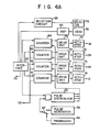
- the method according to this embodiment uses a controller 50 including a microcomputer 51, as shown in Fig. 6A and Fig. 6B.
- a controller 50 including a microcomputer 51, as shown in Fig. 6A and Fig. 6B.
- Fig. 1 mechanical connections between the controller 50 and the first, second and third support members 12, 28 and 34 driven by the controller 50 are represented by imaginary lines.
- the controller 50 is provided with a data memory 52, a priority interrupt circuit 53, and a start switch 54, as well as the microcomputer 51.
- the microcomputer 51 is connected through an interface 55 with an input unit 56, display unit 57, magnetic card reader 58, magnetic tape reader 59, pulse distributor 60, counters 61 to 64, amplifier 65, and selection circuit 66 for the free length of the coil spring. Further, the priority interrupt circuit 53 and the pulse distributor 60 are severally connected with the counters 61 to 64.
- the pulse distributor 60 is connected through a changeover switch 67 with a pulse signal generator 69 which produces a pulse signal corresponding to the feed length of the element wire 40.
- the counters 61 to 64 operate drive units 70 to 73, which drive actuators 74 to 77, respectively.
- the actuators 74, 75, 76 and 77 actuate the first, second and third support members 12, 28 and 34 and the movable shaft 36, respectively.
- the amplifier 65 is connected with a head 78 for detecting the free length of the coil spring 46, and the free length selection circuit 66 is connected with a selector 79 for classifying the coil spring 46.
- data on the coil spring 46 such as the reference values and allowable deviations of the length of the element wire 40 necessary for forming the coil spring, the diameter, pitch and free length of the completed coil spring 46, etc., are stored in the memory section of the microcomputer 51 or in the data memory 52.
- the start switch 54 is operated to interrupt the microcomputer 51, and the counters 61 to 64 are supplied severally with numbers of pulses corresponding to the stored data.
- the pulse distributor 60 When the changeover switch 67 is shifted to the side of a transducer 68, the pulse distributor 60 is supplied with a number of pulses corresponding to the length of the element wire 40 actually fed to a curving mechanism consisting of the support roller 24 and the pressing rollers 16 and 18.
- the pulse generator 69 which may be replaced with the transducer 68 by the operation of the changeover switch 67, is used for supplying suitable pulses to the pulse distributor 60 to check out or adjust the coiling machine or as an emergency measure in case of trouble of the transducer 68.
- the pulse distributor 60 supplies the counters 61 to 64 with a pulse signal corresponding to the actually measured length of the spring element wire supplied thereto. If the pulse signal from the transducer 68 coincides with a previously supplied command signal related to the spring element wire, then the counters 61 to 64 supply the drive units 70 to 73 with a pulse signal for driving the actuators 74 to 77 as required.
- the first, second and third support members 12, 28 and 34 move vertically and the movable shaft 36 moves axially, so that the pressing rollers 16 and 18, pitch tool 32, and end support shaft 37 move as required.
- an operation end signal is delivered from the counters 61 to 64 to interrupt the microcomputer 51 through the priority interrupt circuit 53, and subsequent command signals are supplied from the microcomputer 51 and the data memory 52 to the counters 61 to 64.
- the actuators 74 to 77 are operated in accordance with the command data. Such operation is performed continuously until the coil spring 46 is formed at the forward end of the element wire 40. The coil spring 46 is cut off by the cutter 92 (see Fig.
- the free length of the spring 46 is detected by the free length detecting head 78, and the detection value is transmitted through the amplifier 65 and the interface 55 to the microcomputer 51, where it is compared with the previously stored reference value. If the result of such comparison takes a value exceeding the predetermined value of deviation, the free length selection circuit 66 operates in accordance with the command signal delivered from the microcomputer 51, and the coil spring 46 is classified according to the free length by the selector 79 which is controlled by the circuit 66. These operations can be automatically executed in accordance with programs previously stored in the microcomputer 51 and other memories. Further, if the comparison result or deviation is found to be outside the allowable range, the reference value of the data stored in the computer 51 and/or data memory 32 can be automatically corrected to keep the deviation within the predetermined range.
- the controller 50 operating in the aforementioned manner, a wide variety of coil springs can be formed by variously shifting the positions of the support roller 24, the pair of pressing rollers 16 and 18, and the pitch tool 18 in accordance with instructions from the microcomputer.
- the arrangements for the coil spring forming are simple, and the attachment tools for the coiling machine can be reduced in number. It is not very difficult automatically to control a heat treatment process for the coil spring by means of the microcomputer.
- Figs. 10 and 11 are front and plan views showing the principal part of another coiling machine for executing the method of the invention, respectively.
- pressing rollers 16 and 18 are rotatably attached to support members 12a and 12b, respectively, and can advance and retreat substantially in parallel (transverse direction in the figures) with a path along which an element wire 40 is fed to the rollers 16, 18 and 24.
- Figs. 10 and 11 there are shown a pair of actuators 74a and 74b which drive the support members 12a and 12b, respectively, and a feed roller 90 for the element wire 40, cutter 92, driving shaft 94 for rotating the support roller 24, and driving shafts 96 and 98 for the pressing rollers 16 and 18.
- Each of these driving shafts 94, 96, 98 is designed to be adapted for extension and contraction and each end of the driving shaft is provided with a universal joint. If necessary, one or more driving shafts 92, 94, 96 to be rotated are coupled to power sources for driving the support roller 24 and the pressing rollers 16 and 18.
- this invention is not limited to the manufacture of such springs.
- the method of the invention can be applied to the manufacture of cylindrical springs, conical springs, combinations of these springs, and a coil spring having different partial pitch portions.
- Materials for these coil springs may be a elongated element wire, or cut element wires with a predetermined length, or element wires with other sectional configurations than a circular shape.
- a coil spring can be formed through a hot working, warm working or cold working.
- the support roller 24 is fixed, whereas the pressing rollers 16 and 18 are movable. As shown in Fig. 7, however, only the pressing roller 18 on the down-course side of the element wire 40 may be moved along with the first support member 12 to curve the element wire 40 so that the other pressing roller 16, together with the support roller 24, may hold the element wire 40 to guide the same in a predetermined direction. Moreover, two guide rollers 24a and 16a may be additionally provided to further stabilize the feed path of the element wire 40.
- the guide roller 24a and 16a, support roller 24, and pressing roller 16 may be arranged alternately.
- a plurality of movable projections 92 which support the coil spring being coiled at its maximum-diameter portions, as shown in Fig. 9, or a combination of the movable shaft 36 and the projections 92.
- the movable shaft 36 and the end support shaft 37 attached thereto may be omitted if the coil spring being formed has a relatively short free length or so far as the standards for other dimensions and properties permit.
- all or some of the shafts 14, 26 and 36 may be arranged in a direction which is not parallel with the shaft 22 of the support roller 24.
- the pitch of the coil spring may be determined by rocking the pitch tool 32 instead of moving it in parallel with the shaft 26.
- the pitch tool 32 and the end support shaft 37 are rotatably mounted on their corresponding shafts 30 and 36.
Abstract
Description
- This invention relates to a method of forming a coil spring including feeding an element wire along its longitudinal direction for forming a coil spring.
- Generally known are several methods of forming a coil spring with a desired pitch and diameter by running an element wire in the aforesaid- manner. As an example, there is a method in which the element wire is spirally wound around a core member. This method, however, is subject to the following drawbacks. First, in hot- forming e.g. a barrel-shaped spring, the formed spring cannot be separated from the core bar unless the core member is axially displaced for approximately half a pitch and rotated, so that the manufacture and handling of the core member requires special care. Secondly, the formation of end turn portions with a pitch different from that of the principal part of the coil spring requires a separate process. In order to remove such awkwardness, there is proposed the use of a bevel core member whose external shape can be changed by means of a suitable link mechanism. With use of such core member, however, produced coil springs are liable to become polygonal. Further contrived is a method of manufacturing a coil spring without using any core member. In this method, an element wire running along its longitudinal direction to be curved is pressed against coiling points arranged substantially at right angle to the running direction. Although having many advantages, this method is also subject to some drawbacks as follows. First, this method requires a strongly-built coiling machine because of great force being applied to the coiling points when using an element wire with a large diameter (e.g. 10 mm or more). Secondly, manufacture of only one coil spring requires an element wire with a length corresponding to at least several springs to be fed into the coiling machine, so that the formed coil spring, as well as the coiling machine, cannot help being costly. Tertiary, with scratches or gashes no formed coil springs produced by hot working process are adaptable for practical use.
- The object of this invention is to provide a method of forming a coil spring efficiently with a desired coil diameter independently of the thickness of a spring element wire used by means of a relatively cheap coiling machine free from the aforementioned drawbacks of the prior art coiling machine.
- To this end, a method of forming a coil spring according to this invention comprises feeding an element wire through a first gap defined between a support roller disposed on one side of a feed path of the element wire and having a rotating shaft substantially perpendicular to the path and a first pressing roller disposed on the other side of the path and having a rotating shaft substantially parallel with the support roller, and feeding the element wire passed through the first gap through a second gap defined between the support roller and a second pressing roller disposed on the same side of the element wire as the first pressing roller and having a rotating shaft substantially parallel with the first pressing roller, wherein the winding radius of each portion of the coil spring being determined by pressing the element wire against the surface of the support roller by means of the first and second pressing rollers and curving the element wire with a radius depending on the relative positions of the three rollers.
- Various effects may be obtained with use of the above-mentioned method of coil spring manufacture. First, the coil element wire can be curved with various curvatures by changing the relative positions of the three rollers, so that coil springs with various shapes can be easily formed without using core members of various kinds that are required for the conventional method of coil spring forming by means of core members. Secondly, a coil spring with various diameter portions, such as a conical spring or barrel-shaped spring, can be easily manufactured by controlling the positions of the rollers during the forming operation. Moreover, since the positions of the rollers can be controlled by the use of e.g. a computer, coil springs with substantially correct dimensions can be manufactured by the use of an attachment device for automatically measuring the principal dimensions of finished coil springs, as well as a well-known automatic controller which is used for shifting the roller positions if the measurement results are different from reference values. Further used may be a self-learning circuit which changes the reference values according to the measurement results. The formation of the conical spring or barrel-shaped spring can be automatically performed while storing a computer or suitable memory with roller positions for a coil diameter corresponding to the feed length of the element wire and comparing the stored data with actual measurement data on the element wire length. According to this invention, unlike in the method using the coiling points, the coiling machine is subjected to no great force, and can therefore be of slender build. Further, it is unnecessary continually to feed the coiling machine with a spring element wire having a length corresponding to a plurality of coil springs, so that the material cost required, for example, for trial manufacture of coil springs may be minimized. Moreover, if the rollers are so designed as to rotate at a peripheral speed substantially equal to the running speed of the element wire, the element wire will never be in slide contact with the rollers. Accordingly, it will be possible to prevent the production of scratches on the element wire which may be caused when the element wire runs against the coiling points to be curved. This will not only improve'the strength and external appearance of the products or coil springs, but also reduce the variations in their properties.
- This invention can be more fully understood from the following detailed description when taken in conjunction with the accompanying drawings, in which:
- Fig. 1 shows the principal part of a coiling machine for executing the method of this invention;
- Fig. 2 is a sectional view of the coiling machine as taken along line 2-2 of Fig. 1;
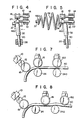
- Fig. 3 shows the relative positions of rollers and a pitch tool where the front end turn portion of a coil spring is being formed;
- Fig. 4 shows the relative positions of the rollers and the pitch tool where a portion of the coil spring apart from the end turn portion is being coiled;
- Fig. 5 shows the relative positions of the rollers and the pitch tool where the rear end turn portion of the coil spring is being formed;
- Figs. 6A and 6B are block diagrams of a controller for operating the coiling machine of Fig. 1;
- Figs. 7 and 8 show alternative examples of the arrangements of support and pressing rollers;
- Fig. 9 shows another example of the method of supporting the coil spring being formed on the coiling machine of Fig. 1; and
- Figs. 10 and 11 are front and plan views of a mechanism for driving the support and pressing rollers, respectively.
- This invention will now be described with reference to the accompanying drawings. Fig. 1 shows an example of the principal part of a coiling machine for executing the method of the invention, and Fig. 2 is a sectional view taken along line 2-2 of Fig. 1. A
frame 10 is fitted with afirst support member 12 capable of vertical movement. Twoshafts 14 which protrude substantially horizontally are rotatably supported to thefirst support member 12, and first and secondpressing rollers frame 10 is rotatably fitted with ashaft 22 extending below theshafts 14 substantially in parallel with theshafts 14, and asupport roller 24 is attached to the tip end of theshaft 22. Theframe 10 is further fitted with ashaft 26 which extends substantially under theshaft 22 and substantially in parallel therewith, and can slide axially. Asecond support member 28 is fixed to the tip end of theshaft 26, ashaft 30 extends through a hole 28a bored through themember 28, and apitch tool 32 is fitted on the upper end portion of theshaft 30. Furthermore, theframe 10 is fitted with athird support member 34 capable of vertical movement. Fitted in themember 34 is amovable shaft 36 which extends substantially horizontally toward thepitch tool 32 and can slide axially. Anend support shaft 37 is attached to the tip end of theshaft 36. - As shown in Figs. 1 and 2, a spring element wire or
material 40 is transferred longitudinally by means of a suitable feed roller (not shown) or by driving all or some of thesupport roller 24 and thepressing rollers gaps support roller 24 and thepressing rollers spring element wire 40 is continuously curved to obtain a desired curvature by moving thefirst support member 12 to control the relative positions of thepressing rollers support roller 24. - In forming a barrel-shaped spring 46 (Fig. 5) after the
second support member 28 is moved to the left of Fig. 4 to give the spring 46 a predetermined pitch, thefirst support member 12 and hence thepressing rollers element wire 40 defined by the relative positions of therollers spring 46 to be formed is coiled. Thereafter, the second half of the barrel-shaped portion and the rear end turn portion 46b of thespring 46 can be formed by shifting the vertical position of thefirst support member 12 and the position of thepitch tool 32 oppositely to the aforesaid manner. During this forming operation, other rollers than the rollers, which drives theelement wire 40 to travel are rotating in contact with thewire 40. - In the aforementioned formation of the coil spring, as may be seen from Figs. 3 to 5, the front end turn portion 46a, along with the following coiled portion of the
element wire 40, tends to move first to the lower left for the coiling of the first half of the barrel-shaped portion, and then to the upper left for the coiling of the second half. If the front end turn portion 46a is left free, then the coiled portion will possibly vibrate and sag by its own gravity. Such vibration and sag can be prevented by moving thethird support member 34 vertically and themovable shaft 36 in the transverse direction of Fig. 1, thereby inserting theend support shaft 37 in the front end turn portion 46a to support the same, and thereafter moving thethird support member 34 and themovable shaft 36 by computer control based on a predetermined program to maintain the support of the front end turn portion 46a. - When the coiling of the rear end turn portion 46b is finished in the aforementioned manner, the
element wire 40 is cut by means of a suitable cutter 92 (see Fig. 10), and the formed coil spring is removed from thesupport roller 24 and themovable shaft 36 to be taken out of the coiling machine. After the coil spring is taken out in this way, themovable shaft 36 is returned to its initial position, and the coiling machine starts to form another barrel-shaped spring. - The above-mentioned coil spring forming operation can be performed by using a mechanical apparatus having a cam mechanism, link mechanism, etc. The method according to this embodiment, however, uses a
controller 50 including amicrocomputer 51, as shown in Fig. 6A and Fig. 6B. In Fig. 1, mechanical connections between thecontroller 50 and the first, second andthird support members controller 50 are represented by imaginary lines. Thecontroller 50 is provided with adata memory 52, apriority interrupt circuit 53, and astart switch 54, as well as themicrocomputer 51. Themicrocomputer 51 is connected through aninterface 55 with aninput unit 56,display unit 57,magnetic card reader 58,magnetic tape reader 59,pulse distributor 60,counters 61 to 64,amplifier 65, andselection circuit 66 for the free length of the coil spring. Further, the priority interruptcircuit 53 and thepulse distributor 60 are severally connected with thecounters 61 to 64. Thepulse distributor 60 is connected through achangeover switch 67 with a pulse signal generator 69 which produces a pulse signal corresponding to the feed length of theelement wire 40. Thecounters 61 to 64 operatedrive units 70 to 73, which drive actuators 74 to 77, respectively. Theactuators third support members movable shaft 36, respectively. Theamplifier 65 is connected with ahead 78 for detecting the free length of thecoil spring 46, and the freelength selection circuit 66 is connected with aselector 79 for classifying thecoil spring 46. - Now there will be given an outline of the operation of the
controller 50. First, data on thecoil spring 46, such as the reference values and allowable deviations of the length of theelement wire 40 necessary for forming the coil spring, the diameter, pitch and free length of the completedcoil spring 46, etc., are stored in the memory section of themicrocomputer 51 or in thedata memory 52. Then, thestart switch 54 is operated to interrupt themicrocomputer 51, and thecounters 61 to 64 are supplied severally with numbers of pulses corresponding to the stored data. When thechangeover switch 67 is shifted to the side of atransducer 68, thepulse distributor 60 is supplied with a number of pulses corresponding to the length of theelement wire 40 actually fed to a curving mechanism consisting of thesupport roller 24 and thepressing rollers transducer 68 by the operation of thechangeover switch 67, is used for supplying suitable pulses to thepulse distributor 60 to check out or adjust the coiling machine or as an emergency measure in case of trouble of thetransducer 68. - In response to a command signal from the
microcomputer 51, thepulse distributor 60 supplies thecounters 61 to 64 with a pulse signal corresponding to the actually measured length of the spring element wire supplied thereto. If the pulse signal from thetransducer 68 coincides with a previously supplied command signal related to the spring element wire, then thecounters 61 to 64 supply thedrive units 70 to 73 with a pulse signal for driving theactuators 74 to 77 as required. Thus, the first, second andthird support members movable shaft 36 moves axially, so that thepressing rollers pitch tool 32, and endsupport shaft 37 move as required. When the operation of theactuators 74 to 77 is completed, an operation end signal is delivered from thecounters 61 to 64 to interrupt themicrocomputer 51 through the priority interruptcircuit 53, and subsequent command signals are supplied from themicrocomputer 51 and thedata memory 52 to thecounters 61 to 64. When the signal delivered from thetransducer 68 reaches a next predetermined value, theactuators 74 to 77 are operated in accordance with the command data. Such operation is performed continuously until thecoil spring 46 is formed at the forward end of theelement wire 40. Thecoil spring 46 is cut off by the cutter 92 (see Fig. 10), the free length of thespring 46 is detected by the freelength detecting head 78, and the detection value is transmitted through theamplifier 65 and theinterface 55 to themicrocomputer 51, where it is compared with the previously stored reference value. If the result of such comparison takes a value exceeding the predetermined value of deviation, the freelength selection circuit 66 operates in accordance with the command signal delivered from themicrocomputer 51, and thecoil spring 46 is classified according to the free length by theselector 79 which is controlled by thecircuit 66. These operations can be automatically executed in accordance with programs previously stored in themicrocomputer 51 and other memories. Further, if the comparison result or deviation is found to be outside the allowable range, the reference value of the data stored in thecomputer 51 and/ordata memory 32 can be automatically corrected to keep the deviation within the predetermined range. - According to the above-mentioned method, many advantages can be obtained. First, by varying the relative positions of the rollers (24, 16, 18) coil springs having a various coil diameters and coil springs each having portions with various diameter are easily produced. Second, formed coil springs can readily be removed from the coiling machine. Tertiary it is not necessary to provide various core members of different shapes and so the cost for providing core members and manufacturing cost for making the coil spring are reduced. Further, the
support roller 24, pressingrollers pitch tool 32 and all rollers in contact with theelement wire 40 run at a peripheral speed substantially equal to the running speed of theelement wire 40, so that it is possible to minimize the incidence of flawing on the element wire due to slip which is a problem in the case of hot forming. Moreover, if the force to roll in the front end of the element wire between thesupport roller 24 and thepressing rollers support roller 24 be substantially equal to the inside diameter of the end turn portion 46a. With use of thecontroller 50 operating in the aforementioned manner, a wide variety of coil springs can be formed by variously shifting the positions of thesupport roller 24, the pair of pressingrollers pitch tool 18 in accordance with instructions from the microcomputer. Thus, the arrangements for the coil spring forming are simple, and the attachment tools for the coiling machine can be reduced in number. It is not very difficult automatically to control a heat treatment process for the coil spring by means of the microcomputer. - Figs. 10 and 11 are front and plan views showing the principal part of another coiling machine for executing the method of the invention, respectively. In this coiling machine, pressing
rollers members 12a and 12b, respectively, and can advance and retreat substantially in parallel (transverse direction in the figures) with a path along which anelement wire 40 is fed to therollers actuators 74a and 74b which drive thesupport members 12a and 12b, respectively, and afeed roller 90 for theelement wire 40,cutter 92, drivingshaft 94 for rotating thesupport roller 24, and drivingshafts pressing rollers shafts more driving shafts support roller 24 and thepressing rollers - By the displacement of the one or both of the
pressing rollers support roller 24, relative positions of the rollers are varied and the radius of curvature of each coil portion is changed. In Fig. 11support roller 24 can be displaced vertically of the drawing and various winding radius be obtained. - Although there has been described herein a method of manufacturing barrel-shaped springs, this invention is not limited to the manufacture of such springs. For example, the method of the invention can be applied to the manufacture of cylindrical springs, conical springs, combinations of these springs, and a coil spring having different partial pitch portions. Materials for these coil springs may be a elongated element wire, or cut element wires with a predetermined length, or element wires with other sectional configurations than a circular shape. According to the method of this invention, a coil spring can be formed through a hot working, warm working or cold working.
- There may be proposed various modifications of the method of coil spring manufacture as follows. In the above-mentioned embodiment, the
support roller 24 is fixed, whereas thepressing rollers pressing roller 18 on the down-course side of theelement wire 40 may be moved along with thefirst support member 12 to curve theelement wire 40 so that the other pressingroller 16, together with thesupport roller 24, may hold theelement wire 40 to guide the same in a predetermined direction. Moreover, two guide rollers 24a and 16a may be additionally provided to further stabilize the feed path of theelement wire 40. - As shown in Fig. 8, moreover, the guide roller 24a and 16a,
support roller 24, and pressingroller 16 may be arranged alternately. - Instead of using the
movable shaft 36 inserted in the front end turn portion 46a, there may be used a plurality ofmovable projections 92 which support the coil spring being coiled at its maximum-diameter portions, as shown in Fig. 9, or a combination of themovable shaft 36 and theprojections 92. Themovable shaft 36 and theend support shaft 37 attached thereto may be omitted if the coil spring being formed has a relatively short free length or so far as the standards for other dimensions and properties permit. Further, all or some of theshafts shaft 22 of thesupport roller 24. Furthermore, the pitch of the coil spring may be determined by rocking thepitch tool 32 instead of moving it in parallel with theshaft 26. In the above embodiment, thepitch tool 32 and theend support shaft 37 are rotatably mounted on theircorresponding shafts
Claims (6)
wherein the winding radius of each portion of said coil spring (46) is determined by pressing said element wire (40) against the surface of said support roller (24) by means of said first and second pressing rollers (16, 18) and curving said element wire. (40) with a radius depending on the relative positions of said three rollers (16, 18, 24).
Applications Claiming Priority (2)
| Application Number | Priority Date | Filing Date | Title |
|---|---|---|---|
| JP9847380A JPS5725233A (en) | 1980-07-18 | 1980-07-18 | Formation of coil spring |
| JP98473/80 | 1980-07-18 |
Publications (3)
| Publication Number | Publication Date |
|---|---|
| EP0044464A2 true EP0044464A2 (en) | 1982-01-27 |
| EP0044464A3 EP0044464A3 (en) | 1982-04-28 |
| EP0044464B1 EP0044464B1 (en) | 1985-03-06 |
Family
ID=14220627
Family Applications (1)
| Application Number | Title | Priority Date | Filing Date |
|---|---|---|---|
| EP81105289A Expired EP0044464B1 (en) | 1980-07-18 | 1981-07-08 | Method of forming a coil spring |
Country Status (7)
| Country | Link |
|---|---|
| US (1) | US4444036A (en) |
| EP (1) | EP0044464B1 (en) |
| JP (1) | JPS5725233A (en) |
| AU (1) | AU530260B2 (en) |
| BR (1) | BR8104626A (en) |
| DE (1) | DE3169175D1 (en) |
| ES (1) | ES504086A0 (en) |
Cited By (11)
| Publication number | Priority date | Publication date | Assignee | Title |
|---|---|---|---|---|
| GB2155828A (en) * | 1984-03-24 | 1985-10-02 | Ae Plc | The manufacture of piston rings |
| EP0322605A2 (en) * | 1987-12-26 | 1989-07-05 | MORITA & COMPANY CO., LTD. | Method of making double-coned coil spring and apparatus therefor |
| EP0352933A2 (en) * | 1988-07-26 | 1990-01-31 | Rockwell International Suspension Systems Company | Method and apparatus for forming a barrel coil spring |
| EP0742061A1 (en) * | 1995-05-11 | 1996-11-13 | Spühl Ag | Electronically controlled winding device for mattresses or upholstery springs |
| US5950473A (en) * | 1997-08-29 | 1999-09-14 | Frank L. Wells Company | Coil spring forming and conveying assembly |
| US6430982B2 (en) | 1997-08-29 | 2002-08-13 | Michael E. Andrea | Coil spring forming and conveying assembly |
| WO2005030411A1 (en) * | 2003-10-02 | 2005-04-07 | Panagiotis Anagnostopoulos | Method and system of production of springs from wire of circular or other cross-sectional area |
| WO2011144854A1 (en) * | 2010-05-17 | 2011-11-24 | H 32 | Method for producing an orthodontic arch or retaining arch, device for performing said method, resulting orthodontic arch or retaining arch and orthodontic appliance comprising same |
| CN105121054A (en) * | 2014-03-25 | 2015-12-02 | 大圆钢业株式会社 | Device for manufacturing hot-rolled coil spring |
| US9402695B2 (en) | 2010-05-17 | 2016-08-02 | H32 | Individualized jig for orthodontic braces, assembly formed by that jig, a base and a bracket, and its design methods |
| EP2599566A4 (en) * | 2010-07-30 | 2016-11-23 | Nhk Spring Co Ltd | Apparatus for manufacturing coil spring |
Families Citing this family (20)
| Publication number | Priority date | Publication date | Assignee | Title |
|---|---|---|---|---|
| AU561706B2 (en) * | 1983-04-01 | 1987-05-14 | Foster Wheeler Energy Corporation | Forming elongated helical shapes from wire |
| US4672549A (en) * | 1984-11-01 | 1987-06-09 | Saxton Richard E | Coil spring forming machine |
| JPS62248529A (en) * | 1986-04-22 | 1987-10-29 | Nhk Spring Co Ltd | Coil spring coiler |
| JPS63116130U (en) * | 1987-01-26 | 1988-07-27 | ||
| JPH0829378B2 (en) * | 1987-01-28 | 1996-03-27 | 株式会社森田鉄工所 | Tal coil spring manufacturing equipment |
| JPH0753298B2 (en) * | 1988-08-24 | 1995-06-07 | 平岡金属工業株式会社 | Spiral rebar manufacturing equipment |
| JPH0777655B2 (en) * | 1992-07-24 | 1995-08-23 | 株式会社板屋製作所 | Spring manufacturing equipment |
| US5647240A (en) * | 1995-07-28 | 1997-07-15 | Newcomb Spring Corporation | Pitch tool holder |
| US6318416B1 (en) | 1997-11-13 | 2001-11-20 | L&P Property Management Company | Spring interior and method of making same |
| US5875664A (en) * | 1997-12-23 | 1999-03-02 | L&P Property Management Company | Programmable servo-motor quality controlled continuous multiple coil spring forming method and apparatus |
| JP4601108B2 (en) * | 2000-01-28 | 2010-12-22 | 中央発條株式会社 | Bent coil spring and method of manufacturing the same |
| JP4712179B2 (en) * | 2000-11-08 | 2011-06-29 | 三菱製鋼株式会社 | Winding spring manufacturing equipment |
| JP4010829B2 (en) * | 2002-02-21 | 2007-11-21 | 中央発條株式会社 | Coil spring manufacturing method and apparatus |
| US7198068B2 (en) * | 2003-08-28 | 2007-04-03 | Meritor Suspension Systems Co. | Cassette pigtailing machine for a coil spring |
| KR100929944B1 (en) * | 2006-02-07 | 2009-12-04 | 도쿄엘렉트론가부시키가이샤 | Storage medium recording the control device of the substrate processing apparatus and the control program of the substrate processing apparatus |
| JP5529262B2 (en) * | 2010-04-19 | 2014-06-25 | オリイメック株式会社 | Conical spring load characteristic adjustment system |
| US8912472B1 (en) * | 2010-07-19 | 2014-12-16 | Barnes Group Inc. | Induction heating of springs |
| DE102013219056B4 (en) * | 2013-09-23 | 2016-06-09 | Fico Cables Lda | METHOD AND DEVICE FOR PRODUCING A SUPPORT MAT AND SUPPORT MAT |
| JP6199139B2 (en) | 2013-09-26 | 2017-09-20 | 中央発條株式会社 | Method and apparatus for forming coil spring |
| US9744584B2 (en) * | 2014-03-25 | 2017-08-29 | Dae Won Kang Up Co., Ltd. | Hot formed coiling machine |
Citations (7)
| Publication number | Priority date | Publication date | Assignee | Title |
|---|---|---|---|---|
| DE552004C (en) * | 1928-04-24 | 1932-06-09 | L A Young Spring & Wire Corp | Machine for the production of coil springs with a knotted winding and device for feeding the finished springs to a collection point |
| US1985392A (en) * | 1933-04-10 | 1934-12-25 | William E Wunderlich | Spring forming machine |
| US2179389A (en) * | 1938-06-24 | 1939-11-07 | United Wire & Supply Corp | Coiling apparatus |
| FR1258118A (en) * | 1960-05-30 | 1961-04-07 | Shumag Schumacher Metallwerke | Control device for producing a feed as a function of a driving movement |
| GB978819A (en) * | 1962-11-14 | 1964-12-23 | Ct De Rech S De Pont A Mousson | Improved method and device for the continuous winding of wire |
| DE2435482A1 (en) * | 1973-07-26 | 1975-02-06 | Sato Spring Seisakusho Kk | METHOD FOR MANUFACTURING COIL SPRINGS |
| DE2628937A1 (en) * | 1976-06-28 | 1977-12-29 | Hans Lindemann | Machine for making helical coil springs - has wire shearing tool mounted in sliding carriage driven by leadscrew |
Family Cites Families (13)
| Publication number | Priority date | Publication date | Assignee | Title |
|---|---|---|---|---|
| US204030A (en) * | 1878-05-21 | Improvement in wire-coiling machines | ||
| US432741A (en) * | 1890-07-22 | sptjhl | ||
| CA636198A (en) * | 1962-02-06 | Union Carbide Canada Limited | Helical coil bending machine | |
| GB356428A (en) * | 1930-08-13 | 1931-09-10 | Emil Spuhl | Improvements in or relating to coiling machines for helical springs |
| US1930329A (en) * | 1933-03-06 | 1933-10-10 | Burton Dixie Corp | Spring coiling machine |
| US2339424A (en) * | 1942-02-17 | 1944-01-18 | Gen Motors Corp | Tube coiling device |
| FR1237120A (en) * | 1958-02-03 | 1960-07-29 | Tube coil forming machine | |
| US3420080A (en) * | 1966-06-23 | 1969-01-07 | Applied Science Lab Inc | Coiling device |
| US3996779A (en) * | 1975-02-10 | 1976-12-14 | Western Gear Corporation | Pipe storage apparatus and method |
| US4112721A (en) * | 1976-04-07 | 1978-09-12 | Nhk Spring Co., Ltd. | Nc coil spring manufacturing apparatus |
| JPS52142260A (en) * | 1976-05-24 | 1977-11-28 | Hitachi Ltd | Winding machine |
| JPS5367670A (en) * | 1976-11-30 | 1978-06-16 | Nikkei Kk | Ring form method and terminal bend device and ring form device |
| JPS6050527B2 (en) * | 1977-04-22 | 1985-11-08 | セイコ−電子部品株式会社 | Mainspring processing equipment |
-
1980
- 1980-07-18 JP JP9847380A patent/JPS5725233A/en active Granted
-
1981
- 1981-07-08 EP EP81105289A patent/EP0044464B1/en not_active Expired
- 1981-07-08 DE DE8181105289T patent/DE3169175D1/en not_active Expired
- 1981-07-10 US US06/281,946 patent/US4444036A/en not_active Expired - Lifetime
- 1981-07-13 AU AU72802/81A patent/AU530260B2/en not_active Ceased
- 1981-07-17 BR BR8104626A patent/BR8104626A/en not_active IP Right Cessation
- 1981-07-17 ES ES504086A patent/ES504086A0/en active Granted
Patent Citations (7)
| Publication number | Priority date | Publication date | Assignee | Title |
|---|---|---|---|---|
| DE552004C (en) * | 1928-04-24 | 1932-06-09 | L A Young Spring & Wire Corp | Machine for the production of coil springs with a knotted winding and device for feeding the finished springs to a collection point |
| US1985392A (en) * | 1933-04-10 | 1934-12-25 | William E Wunderlich | Spring forming machine |
| US2179389A (en) * | 1938-06-24 | 1939-11-07 | United Wire & Supply Corp | Coiling apparatus |
| FR1258118A (en) * | 1960-05-30 | 1961-04-07 | Shumag Schumacher Metallwerke | Control device for producing a feed as a function of a driving movement |
| GB978819A (en) * | 1962-11-14 | 1964-12-23 | Ct De Rech S De Pont A Mousson | Improved method and device for the continuous winding of wire |
| DE2435482A1 (en) * | 1973-07-26 | 1975-02-06 | Sato Spring Seisakusho Kk | METHOD FOR MANUFACTURING COIL SPRINGS |
| DE2628937A1 (en) * | 1976-06-28 | 1977-12-29 | Hans Lindemann | Machine for making helical coil springs - has wire shearing tool mounted in sliding carriage driven by leadscrew |
Cited By (18)
| Publication number | Priority date | Publication date | Assignee | Title |
|---|---|---|---|---|
| GB2155828A (en) * | 1984-03-24 | 1985-10-02 | Ae Plc | The manufacture of piston rings |
| EP0322605A2 (en) * | 1987-12-26 | 1989-07-05 | MORITA & COMPANY CO., LTD. | Method of making double-coned coil spring and apparatus therefor |
| EP0322605A3 (en) * | 1987-12-26 | 1989-12-06 | Morita Iron Works Co., Ltd. | Method of making double-coned coil spring and apparatus therefor |
| EP0352933A2 (en) * | 1988-07-26 | 1990-01-31 | Rockwell International Suspension Systems Company | Method and apparatus for forming a barrel coil spring |
| EP0352933A3 (en) * | 1988-07-26 | 1990-10-24 | Rockwell International Suspension Systems Company | Method and apparatus for forming a barrel coil spring |
| EP0742061A1 (en) * | 1995-05-11 | 1996-11-13 | Spühl Ag | Electronically controlled winding device for mattresses or upholstery springs |
| US5713115A (en) * | 1995-05-11 | 1998-02-03 | Spuehl Ag | Electronically regulated apparatus for coiling springs |
| US6430982B2 (en) | 1997-08-29 | 2002-08-13 | Michael E. Andrea | Coil spring forming and conveying assembly |
| US5950473A (en) * | 1997-08-29 | 1999-09-14 | Frank L. Wells Company | Coil spring forming and conveying assembly |
| WO2005030411A1 (en) * | 2003-10-02 | 2005-04-07 | Panagiotis Anagnostopoulos | Method and system of production of springs from wire of circular or other cross-sectional area |
| EA008178B1 (en) * | 2003-10-02 | 2007-04-27 | Панагиотис Анагностопулос | Method and system of production of springs from wire of circular or other cross-sectional area |
| CN100408222C (en) * | 2003-10-02 | 2008-08-06 | 帕纳约蒂斯·阿纳格诺斯托波洛斯 | Method and system of production of springs from wire of circular or other cross-sectional area |
| WO2011144854A1 (en) * | 2010-05-17 | 2011-11-24 | H 32 | Method for producing an orthodontic arch or retaining arch, device for performing said method, resulting orthodontic arch or retaining arch and orthodontic appliance comprising same |
| CN103002829A (en) * | 2010-05-17 | 2013-03-27 | H32公司 | Method for producing an orthodontic arch or retaining arch, device for performing said method, resulting orthodontic arch or retaining arch and orthodontic appliance comprising same |
| US9402695B2 (en) | 2010-05-17 | 2016-08-02 | H32 | Individualized jig for orthodontic braces, assembly formed by that jig, a base and a bracket, and its design methods |
| EP2599566A4 (en) * | 2010-07-30 | 2016-11-23 | Nhk Spring Co Ltd | Apparatus for manufacturing coil spring |
| CN105121054A (en) * | 2014-03-25 | 2015-12-02 | 大圆钢业株式会社 | Device for manufacturing hot-rolled coil spring |
| CN105121054B (en) * | 2014-03-25 | 2017-06-20 | 大圆钢业株式会社 | Hot coiling spring manufacture device |
Also Published As
| Publication number | Publication date |
|---|---|
| JPS5725233A (en) | 1982-02-10 |
| ES8204929A1 (en) | 1982-05-16 |
| AU530260B2 (en) | 1983-07-07 |
| EP0044464A3 (en) | 1982-04-28 |
| ES504086A0 (en) | 1982-05-16 |
| DE3169175D1 (en) | 1985-04-11 |
| JPS6350098B2 (en) | 1988-10-06 |
| AU7280281A (en) | 1982-01-21 |
| BR8104626A (en) | 1982-04-06 |
| EP0044464B1 (en) | 1985-03-06 |
| US4444036A (en) | 1984-04-24 |
Similar Documents
| Publication | Publication Date | Title |
|---|---|---|
| EP0044464B1 (en) | Method of forming a coil spring | |
| EP1461172B1 (en) | Two wire spring making machine and method | |
| KR100319344B1 (en) | Method and apparatus for manufacturing slide fastener continuous element row | |
| US5243746A (en) | Method for manufacturing coil springs | |
| US4947670A (en) | Universal automatic spring-making machine | |
| US5259226A (en) | Mechanism for forming spring pitch | |
| US5875666A (en) | Spring manufacturing apparatus and position adjustment apparatus for tools | |
| US6701765B2 (en) | Spring manufacturing apparatus | |
| US4542635A (en) | Apparatus for manufacturing solid tension coil springs having attachment loops at both ends thereof | |
| JPS6319252B2 (en) | ||
| US4412438A (en) | Pipe bending machine | |
| DE19534189A1 (en) | Spring winding device with reproducible parameters and narrow tolerances | |
| US4408639A (en) | Coil Manufacturing apparatus | |
| US2793672A (en) | Method of close coiling sheathed spring wire | |
| EP1041237B1 (en) | Method and arrangement for automatic bow adjustment of venetian blind slats | |
| JP2022040718A (en) | Spring forming device and spring forming method | |
| JPS6363294B2 (en) | ||
| EP0804978A1 (en) | Twisting or bending machine for making either mono or double winding coil springs | |
| KR100442907B1 (en) | Spring forming machine | |
| GB2093382A (en) | Skeining device | |
| KR100386678B1 (en) | A device to form coiled springs for lathe | |
| JPH0325248B2 (en) | ||
| KR100290115B1 (en) | Hook Spring Manufacturing Equipment | |
| US2779384A (en) | Wire feeding and straightening apparatus | |
| WO1996038240A1 (en) | Methods and means for forming spring coils |
Legal Events
| Date | Code | Title | Description |
|---|---|---|---|
| PUAI | Public reference made under article 153(3) epc to a published international application that has entered the european phase |
Free format text: ORIGINAL CODE: 0009012 |
|
| 17P | Request for examination filed |
Effective date: 19810708 |
|
| AK | Designated contracting states |
Designated state(s): DE FR GB IT |
|
| PUAL | Search report despatched |
Free format text: ORIGINAL CODE: 0009013 |
|
| AK | Designated contracting states |
Designated state(s): DE FR GB IT |
|
| ITF | It: translation for a ep patent filed |
Owner name: JACOBACCI & PERANI S.P.A. |
|
| GRAA | (expected) grant |
Free format text: ORIGINAL CODE: 0009210 |
|
| AK | Designated contracting states |
Designated state(s): DE FR GB IT |
|
| REF | Corresponds to: |
Ref document number: 3169175 Country of ref document: DE Date of ref document: 19850411 |
|
| ET | Fr: translation filed | ||
| PLBE | No opposition filed within time limit |
Free format text: ORIGINAL CODE: 0009261 |
|
| STAA | Information on the status of an ep patent application or granted ep patent |
Free format text: STATUS: NO OPPOSITION FILED WITHIN TIME LIMIT |
|
| 26N | No opposition filed | ||
| ITTA | It: last paid annual fee | ||
| PGFP | Annual fee paid to national office [announced via postgrant information from national office to epo] |
Ref country code: FR Payment date: 19980610 Year of fee payment: 18 |
|
| PGFP | Annual fee paid to national office [announced via postgrant information from national office to epo] |
Ref country code: DE Payment date: 19980616 Year of fee payment: 18 |
|
| PGFP | Annual fee paid to national office [announced via postgrant information from national office to epo] |
Ref country code: GB Payment date: 19980629 Year of fee payment: 18 |
|
| PG25 | Lapsed in a contracting state [announced via postgrant information from national office to epo] |
Ref country code: GB Free format text: LAPSE BECAUSE OF NON-PAYMENT OF DUE FEES Effective date: 19990708 |
|
| PG25 | Lapsed in a contracting state [announced via postgrant information from national office to epo] |
Ref country code: FR Free format text: THE PATENT HAS BEEN ANNULLED BY A DECISION OF A NATIONAL AUTHORITY Effective date: 19990731 |
|
| GBPC | Gb: european patent ceased through non-payment of renewal fee |
Effective date: 19990708 |
|
| PG25 | Lapsed in a contracting state [announced via postgrant information from national office to epo] |
Ref country code: DE Free format text: LAPSE BECAUSE OF NON-PAYMENT OF DUE FEES Effective date: 20000503 |
|
| REG | Reference to a national code |
Ref country code: FR Ref legal event code: ST |