EP0033492A1 - Process and device for producing a dental crown part - Google Patents
Process and device for producing a dental crown part Download PDFInfo
- Publication number
- EP0033492A1 EP0033492A1 EP81100483A EP81100483A EP0033492A1 EP 0033492 A1 EP0033492 A1 EP 0033492A1 EP 81100483 A EP81100483 A EP 81100483A EP 81100483 A EP81100483 A EP 81100483A EP 0033492 A1 EP0033492 A1 EP 0033492A1
- Authority
- EP
- European Patent Office
- Prior art keywords
- tooth stump
- model
- contour
- probe
- memory
- Prior art date
- Legal status (The legal status is an assumption and is not a legal conclusion. Google has not performed a legal analysis and makes no representation as to the accuracy of the status listed.)
- Withdrawn
Links
Classifications
-
- A—HUMAN NECESSITIES
- A61—MEDICAL OR VETERINARY SCIENCE; HYGIENE
- A61C—DENTISTRY; APPARATUS OR METHODS FOR ORAL OR DENTAL HYGIENE
- A61C19/00—Dental auxiliary appliances
- A61C19/04—Measuring instruments specially adapted for dentistry
-
- A—HUMAN NECESSITIES
- A61—MEDICAL OR VETERINARY SCIENCE; HYGIENE
- A61C—DENTISTRY; APPARATUS OR METHODS FOR ORAL OR DENTAL HYGIENE
- A61C13/00—Dental prostheses; Making same
- A61C13/0003—Making bridge-work, inlays, implants or the like
- A61C13/0004—Computer-assisted sizing or machining of dental prostheses
-
- A—HUMAN NECESSITIES
- A61—MEDICAL OR VETERINARY SCIENCE; HYGIENE
- A61C—DENTISTRY; APPARATUS OR METHODS FOR ORAL OR DENTAL HYGIENE
- A61C5/00—Filling or capping teeth
- A61C5/70—Tooth crowns; Making thereof
- A61C5/77—Methods or devices for making crowns
-
- G—PHYSICS
- G05—CONTROLLING; REGULATING
- G05B—CONTROL OR REGULATING SYSTEMS IN GENERAL; FUNCTIONAL ELEMENTS OF SUCH SYSTEMS; MONITORING OR TESTING ARRANGEMENTS FOR SUCH SYSTEMS OR ELEMENTS
- G05B19/00—Programme-control systems
- G05B19/02—Programme-control systems electric
- G05B19/42—Recording and playback systems, i.e. in which the programme is recorded from a cycle of operations, e.g. the cycle of operations being manually controlled, after which this record is played back on the same machine
- G05B19/4202—Recording and playback systems, i.e. in which the programme is recorded from a cycle of operations, e.g. the cycle of operations being manually controlled, after which this record is played back on the same machine preparation of the programme medium using a drawing, a model
- G05B19/4207—Recording and playback systems, i.e. in which the programme is recorded from a cycle of operations, e.g. the cycle of operations being manually controlled, after which this record is played back on the same machine preparation of the programme medium using a drawing, a model in which a model is traced or scanned and corresponding data recorded
-
- G—PHYSICS
- G16—INFORMATION AND COMMUNICATION TECHNOLOGY [ICT] SPECIALLY ADAPTED FOR SPECIFIC APPLICATION FIELDS
- G16H—HEALTHCARE INFORMATICS, i.e. INFORMATION AND COMMUNICATION TECHNOLOGY [ICT] SPECIALLY ADAPTED FOR THE HANDLING OR PROCESSING OF MEDICAL OR HEALTHCARE DATA
- G16H20/00—ICT specially adapted for therapies or health-improving plans, e.g. for handling prescriptions, for steering therapy or for monitoring patient compliance
- G16H20/40—ICT specially adapted for therapies or health-improving plans, e.g. for handling prescriptions, for steering therapy or for monitoring patient compliance relating to mechanical, radiation or invasive therapies, e.g. surgery, laser therapy, dialysis or acupuncture
Definitions
- the procedure is normally that the dentist first grinds the tooth to be replaced, so that a tooth stump is produced, to which the crown part can later be attached. Then a plaster cast of the entire ring gear including the ground tooth stump is made testifies and made a plaster model of the ring gear from it.
- the plaster model is also referred to as a saw model. Individual teeth can be cut out of it by vertical saw cuts in order to be processed separately. Wax is applied to the plaster model of the tooth stump as a molding material.
- the wax is processed according to the shape of the tooth to be replaced with a contour tool, such as a milling cutter. In this process it must be ensured that a certain minimum thickness of the wax layer is maintained on all parts of the peripheral surface of the tooth stump.
- the wax model produced in this way is removed from the tooth stump and used as a casting model for the crown part.
- the crown part is made of a high quality material, e.g. gold.
- a similar process takes place in the manufacture of telescopic crowns.
- a primary part e.g. made of gold
- a secondary part is pushed onto the primary part, which carries the artificial tooth and can also consist of gold.
- the object of the invention is to develop the method of the type mentioned in such a way that when processing the molding material applied to the model of the tooth stump it is ensured that all points on the surface of the tooth stump are covered with a sufficiently thick layer of molding material.
- the contour of the tooth stump is scanned and the contour data are stored, the contour data are retained and accessible even if the tooth stump is coated with a layer of molding material, for example wax.
- the processing of the molding material takes place taking into account the contour data of the tooth stump located under the molding material, so that it is ensured that the Mold material layer is not removed too far at any point, or. gets too thin.
- it can also be ensured, for example in the production of the primary part of a secondary crown, that the material thickness of the casting model - and thus also the material thickness of the crown part to be produced according to the casting model - does not become greater than is absolutely necessary.
- the crown part thus has an optimal wall thickness, which is sufficiently thick at all points on the surface of the tooth stump, but at no point is thicker than necessary. This at least partially automates the very difficult process of shaping the casting model (wax model). Automation avoids the creation of committee work and also ensures that no more gold is used for the crown part than is absolutely necessary.
- the outer surface of the primary part still requires fine machining or smoothing in order to eliminate casting errors.
- This fine machining can also take place taking into account the stored shape data of the tooth stump in that the crown part produced according to the casting model is placed on the model of the tooth stump and fine-machined according to the calculated contour of the casting model, but with a small minimum dimension. It is particularly advantageous here that the crown part experiences constant material removal at all points on its surface, which cannot be achieved with manual processing. This eliminates roughness and imperfections on the surface of the crown part, and yet the crown part is matched exactly to the shape of the tooth stump on which it is to be placed.
- a device for carrying out the method according to the invention is characterized in that a numerically controlled processing machine is equipped with a clamping device for the model of a group of teeth or a tooth stump and has a probe head and a guide device for guiding the probe head along the tooth stump such that the probe head is connected to a memory is connected, which stores position data generated when the probe is guided along the tooth stump, and that, instead of or in addition to the probe, a contour tool is provided which, depending on the content of the memory, can be moved relative to the tooth stump under the control of a computer.
- the probe Before processing takes place, the probe is first guided along the tooth stump in order to enter the surface data of the tooth stump into the memory. Then the molding material is applied to the tooth stump and then the automatic processing of the applied molding material. During these processes, the model of the tooth stump remains immovably fixed in the clamping device. This has the advantage that the selected or. The zero point specified by the processing machine is not adjusted or must be converted into another coordinate system.
- the probe and the contour tool In the processing machine, the probe and the contour tool must be able to be guided or moved relative to the workpiece. It is irrelevant whether the workpiece is stationary and the probe, or. the contour tool is moved or whether the workpiece (model) is moved in a spatial coordinate system and the probe or the contour tool are arranged in a fixed position.
- the probe has a touch sensor for recording the contour data of the tooth stump, which only allows position data to be stored in the memory when the probe touches another part. This ensures that position data is only entered into the memory when the probe is in contact with the model to be scanned.
- a plaster model 10 of the toothed ring in question is produced in a known manner.
- a tooth that was to be replaced was ground in the patient's mouth so that a tooth stump was formed.
- the model of the tooth stump is designated 11 in FIG. 1.
- individual teeth can be separated out by vertical saw cuts 12 so that they can be processed separately.
- the plaster model 10 is attached to a processing machine with a clamping device.
- the processing machine has a stylus 13, at the end of which there is a probe 14.
- the probe 14 is now moved along the outer surface of the tooth stump 11. This can be done, for example, by the probe 14 being successively guided around the tooth stump 11 on circular paths at different heights.
- the stylus 13 can for example be moved by hand so that the probe 14 scans the surface of the tooth stump 11.
- the position of the probe 14 is determined in each case via a coordinate guide device and input into a memory.
- the memory contains the geometric data of the surface of the tooth stump 11.
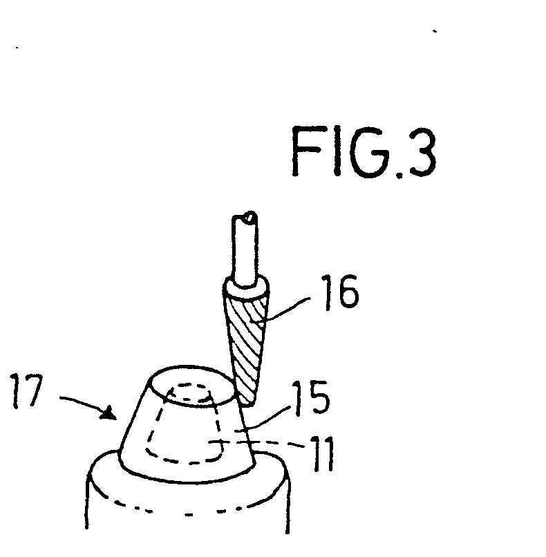
- the stylus 13 is replaced by a contour tool, for example a milling cutter 16, which can rotate about its axis, and one connected to the memory Computer is performed such that the wax layer 15 receives a constant thickness at all points.
- the wax model 17 of the tooth stump produced in this way thus has a constant wall thickness. This is achieved in that the contour data of the tooth stump 11 are processed in the computer in such a way that material is added and that the milling cutter 16 is then moved by the computer along the calculated outer contour of the wax model 17.
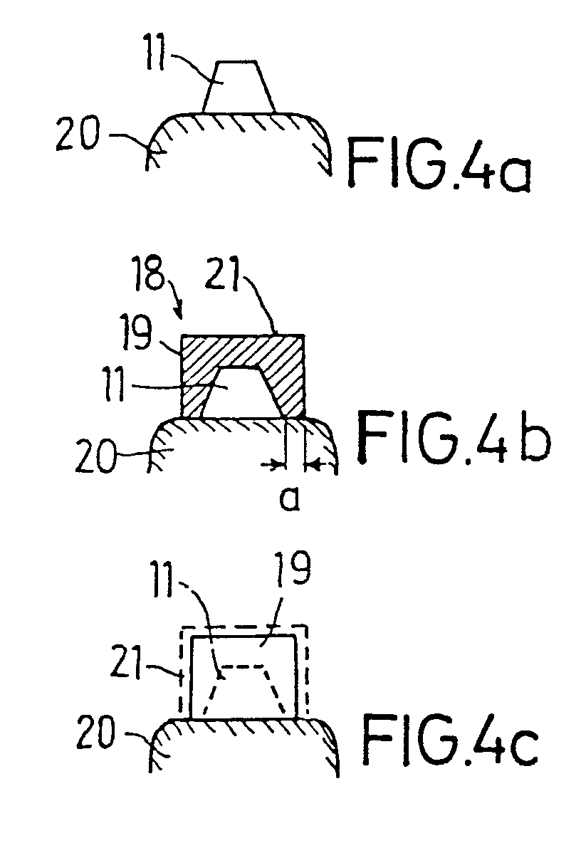
- FIG. 4 shows the various work steps in the production of a crown part 19 as the primary part of a telescopic crown.
- the tooth stump 11 is first scanned and its position data are entered into a memory. Then the tooth stump 11 is surrounded with a wax layer, from which the wax model 18 is shaped in such a way that the wax model is given a peripheral outer wall 19 that rises vertically from the jaw 20 and ends above the tooth stump 11 with a horizontal end face 21.
- This shaping means that the crown part to be produced according to the wax model 18 can be lifted vertically from the jaw 20, even if this crown part is connected to several artificial teeth in the form of a bridge.
- This fine machining is also carried out by the numerically controlled processing machine, which contains the outer contour of the wax model 18 it produces by milling, and only needs to carry out the fine machining with a small minimum dimension 21.
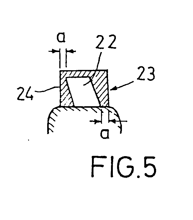
- the plaster model 22 of a tooth stump shown in FIG. 5 is inclined obliquely to the side.
- the wax model 23 of the crown part to be produced here also has parallel vertical walls 24, the wall thickness being calculated so that the minimum thickness a does not fall below a predetermined value in all areas.
- the computer thus calculates the course of the side walls 24 in such a way that the minimum thickness a is not exceeded at any point.
- FIG. 6 shows a processing machine 30 which has a clamping device 31 on which the tooth model 10 (FIG. 1) can be attached.
- the clamping device 31 is fastened on a transverse support 33, which can be rotated about a vertical axis and can be moved in the direction of the Y axis on a longitudinal support 34.
- the longitudinal support 34 can be moved in the direction of the X axis on a base plate 35.
- the transverse support 33 is guided in a guide rail 36, which also runs on the longitudinal support 34, while the longitudinal support 34 is guided in a guide rail 37 of a vertically movable lifting plate 32.
- the longitudinal support 34 and the transverse support 33 are included Provide (not shown) drive means with which they can be moved along the guide rails 37 and 36 in a controlled manner.
- An upstanding stand 38 is fastened to the base plate 35 and has a vertical guide rail 39 in which a vertical guide part 32 ′ of the lifting plate 32 is guided.
- the stand 38 carries a freely projecting beam 40, from which a rotationally drivable spindle 41 projects freely downwards in the direction of the clamping device 31.
- the stylus 13 is attached to the spindle 41.
- the cross support 33 has a position sensor 42 which scans the line markings 43 which are provided on the longitudinal support 34 in the direction of the v-axis and in this way determines the position of the cross support in the direction of the Y-axis in numerical data.
- the longitudinal support 34 has a position sensor 44 which responds to position markings 45 which are attached to the base plate 35 parallel to the guide rails 37.
- the position sensor 44 thus determines the position of the longitudinal support 34 in the longitudinal direction.
- a third position sensor 46 is attached to the guide part 32 '.
- the position transmitter 46 reacts to position markings 47 which are attached parallel to the guide rail 39 along the stand 38 and determines the position of the lifting plate 40 and thus also the position of the probe head of the stylus 13 in the Z direction.
- the position data of all three position transmitters 42, 44 and 46 are fed to an electronic memory 48.
- the entry in the memory takes place only if a contact with another object is detected on the probe. This is communicated to the memory 48 via a control line 49.
- the plaster model 10 is fastened on the clamping device 31, then e.g. Manual movements of the longitudinal support 34, the transverse support 33 and the lifting plate 32 ensure that the probe 14 is moved along the surface of the tooth stump 11.
- the XY and Z data are stored in the memory for each contact point or surface point of the tooth stump 48 registered. An image of the outer surface of the tooth stump is created in the memory 48 on the basis of this position data.
- the memory 48 is connected to a computer 50, which calculates the outer contour of the wax model to be produced from the determined outer contour of the tooth stump, taking into account the specified boundary conditions, for example a minimum material thickness a or the fact that the side walls of the wax model should be vertical or conical .
- the computer 50 outputs position values D for the position of the transverse support 33, D y for the position of the longitudinal support 34 and D z for the vertical position of the lifting plate 32.
- This position data changes in such a way that the milling cutter 16 is moved along the desired contour of the wax model until the wax model has assumed the outer contour determined by the computer 50.
- the signals from position transmitters 42, 44 and 46 are also fed back to controller 50 as feedback signals.
- the three coordinate values X, Y and Z are sufficient for the numerical definition of the outer contour of a workpiece be pivotable around so that the spindle 40 can be pivoted out of its vertical basic position.
- the rotational or pivoting positions of the parts 40 'and 31 can also be detected by position sensors and fed to the memory 48 or the computer 50.
Abstract
Zur Herstellung eines auf einem Zahnstumpf zu befestigenden Kronenteiles wird zunächst ein Gipsmodell des Zahnstumpfes hergestellt. Die Kontur dieses Gipsmodells wird mit einem Taststift (13) abgetastet und die Konturdaten werden in einen Speicher (43) eingegeben. Aus den Konturdaten wird in einem Rechner (50) die Kontur des herzustellenden Kronenteiles und der Materialzugabe errechnet. Auf das Gipsmodell des Zahnstumpfes wird ein Formmaterial aufgetragen und anschließend wird ein Werkzeug (16) entsprechend der vom Rechner (50) gelieferten Kontur geführt, um das Formmaterial zu bearbeiten.To produce a crown part to be attached to a tooth stump, a plaster model of the tooth stump is first produced. The contour of this plaster model is scanned with a stylus (13) and the contour data are entered into a memory (43). The contour of the crown part to be produced and the material addition are calculated from the contour data in a computer (50). A molding material is applied to the plaster model of the tooth stump and then a tool (16) is guided according to the contour supplied by the computer (50) in order to machine the molding material.
Description
Die Erfindung betrifft ein Verfahren zur Herstellung eines auf einem Zahnstumpf zu befestigenden Kronenteiles, bei welchem
- a) ein Modell des Zahnstumpfes hergestellt wird,
- b) auf das Modell ein Formmaterial aufgetragen wird,
- c) die Außenkontur des Formmaterials durch Materialabtrag verformt wird, und
- d) das Formmaterial von dem Modell entfernt und als Gießmodell für das Kronenteil benutzt wird, sowie eine Vorrichtung zur Durchführung des Verfahrens.
- a) a model of the tooth stump is produced,
- b) a molding material is applied to the model,
- c) the outer contour of the molding material is deformed by material removal, and
- d) the molding material is removed from the model and used as a casting model for the crown part, and a device for carrying out the method.
Bei der Herstellung von Kronen für den Zahnersatz wird normalerweise so vorgegangen, daß zunächst der Zahnarzt den zu ersetzenden Zahn abschleift, so daß ein Zahnstumpf erzeugt wird, an dem später das Kronenteil befestigt werden kann. Anschließend wird ein Gipsabdruck des gesamten Zahnkranzes einschließlich des abgeschliffenen Zahnstumpfes erzeugt und hieraus ein Gipsmodell des Zahnkranzes hergestellt. Das Gipsmodell wird auch als Sägemodell bezeichnet. Aus ihm können einzelne Zähne durch vertikale Sägeschnitte herausgetrennt werden, um separat bearbeitet zu werden. Auf das Gipsmodell des Zahnstumpfes wird Wachs als Formmaterial aufgetragen. Das Wachs wird entsprechend der Form des zu ersetzenden Zahnes mit einem Konturwerkzeug, z.B. einem Fräser, bearbeitet. Bei diesem Vorgang muß sichergestellt werden, daß auf allen Teilen der Umfangsfläche des Zahnstumpfes eine bestimmte Mindeststärke der Wachsschicht aufrechterhalten wird. Da der Zahntechniker beim Abfräsen des Wachses nicht sehen kann, wie stark die Wachsschicht an den einzelnen Stellen ist, erfordert dieser Vorgang ein Höchstmaß von Erfahrung und Feingefühl. Das so erzeugte Wachsmodell wird von dem Zahnstumpf abgenommen und als Gießmodell für das Kronenteil benutzt. Das Kronenteil wird aus einem hochwertigen Material, z.B. Gold, hergestellt.In the manufacture of crowns for dentures, the procedure is normally that the dentist first grinds the tooth to be replaced, so that a tooth stump is produced, to which the crown part can later be attached. Then a plaster cast of the entire ring gear including the ground tooth stump is made testifies and made a plaster model of the ring gear from it. The plaster model is also referred to as a saw model. Individual teeth can be cut out of it by vertical saw cuts in order to be processed separately. Wax is applied to the plaster model of the tooth stump as a molding material. The wax is processed according to the shape of the tooth to be replaced with a contour tool, such as a milling cutter. In this process it must be ensured that a certain minimum thickness of the wax layer is maintained on all parts of the peripheral surface of the tooth stump. Since the dental technician cannot see how thick the wax layer is at the individual points when milling off the wax, this process requires a high degree of experience and sensitivity. The wax model produced in this way is removed from the tooth stump and used as a casting model for the crown part. The crown part is made of a high quality material, e.g. gold.
Ein ähnlicher Vorgang findet bei der Herstellung von Teleskopkronen statt. Hierbei wird auf dem Zahnstumpf ein Primärteil,z.B. aus Gold, befestigt, das dem Zahnstumpf exakt angepaßt ist. Auf das Primärteil wird ein Sekundärteil aufgeschoben, das den künstlichen Zahn trägt und ebenfalls aus Gold bestehen kann.A similar process takes place in the manufacture of telescopic crowns. Here, a primary part, e.g. made of gold, attached, which is exactly adapted to the tooth stump. A secondary part is pushed onto the primary part, which carries the artificial tooth and can also consist of gold.
Die Herstellung derartiger Kronenteile erfordert vom Zahntechniker nicht nur viel Erfahrung und außerordentlich genaue Arbeit, sondern es ergeben sich wegen des hochwertigen Kronenmaterials im Falle eines unzureichenden Arbeitsergebnisses auch hohe Materialkosten.The manufacture of such crown parts not only requires a great deal of experience and extremely precise work from the dental technician, but also high material costs result from the high-quality crown material in the event of an inadequate work result.
Aufgabe der Erfindung ist es, das Verfahren der eingangs genannten Art derart weiterzubilden, daß bei der Bearbeitung des auf das Modell des Zahnstumpfes aufgetragenen Formmaterials sichergestellt ist, daß alle Stellen der Oberfläche des Zahnstumpfes mit einer hinreichend starken Formmaterialschicht bedeckt sind.The object of the invention is to develop the method of the type mentioned in such a way that when processing the molding material applied to the model of the tooth stump it is ensured that all points on the surface of the tooth stump are covered with a sufficiently thick layer of molding material.
Zur Lösung dieser Aufgabe ist erfindungsgemäß vorgesehen, daß
- a1) die Kontur des Zahnstumpfes mindestens teilweise abgetastet und in geometrische Daten umgesetzt wird,
- a2) die geometrischen Daten in einen Speicher eingegeben werden,
- a3) aus den geometrischen Daten die Kontur des Gießmodells unter Materialzugabe auf der gesamten Außenfläche des Zahnstumpfes errechnet wird
- c1) und ein Konturwerkzeug entsprechend der errechneten Kontur des Gießmodells an dem auf dem Abdruck des Zahnstumpfes angeordneten Formmaterial entlanggeführt wird.
- a1) the contour of the tooth stump is at least partially scanned and converted into geometric data,
- a2) the geometric data are entered into a memory,
- a3) the contour of the casting model is calculated from the geometric data with the addition of material on the entire outer surface of the tooth stump
- c1) and a contour tool corresponding to the calculated contour of the casting model is guided along the molding material arranged on the impression of the tooth stump.
Dadurch, daß die Kontur des Zahnstumpfes abgetastet und die Konturdaten gespeichert werden, bleiben die Konturdaten auch dann erhalten und zugänglich, wenn der Zahnstumpf mit einer Schicht aus Formmaterial, z.B. Wachs, beschichtet ist. Die Bearbeitung des Formmaterials erfolgt unter Berücksichtigung der Konturdaten des unter dem Formmaterial befindlichen Zahnstumpfes, so daß sichergestellt ist, daß die Formmaterialschicht an keiner Stelle zu weit abgetragen wird,bzw. zu dünn wird. Andererseits kann, z.B. bei der Herstellung des Primärteiles einer Sekundärkrone,auch sichergestellt werden, daß die Materialstärke des Gießmodelles - und damit auch die Materialstärke des nach dem Gießmodell herzustellenden Kronenteiles.- nicht größer wird als unbedingt erforderlich ist. Das Kronenteil erhält somit eine optimale Wandstärke, die an allen Stellen der Fläche des Zahnstumpfes hinreichend stark, an keiner Stelle aber stärker als notwendig ist. Der sehr schwierige Vorgang der Formgebung des Gießmodelles (Wachsmodelles) wird dadurch wenigstens teilweise automatisiert. Durch die Automatisierung wird die Entstehung von Ausschußarbeit vermieden und darüber hinaus sichergestellt, daß für das Kronenteil nicht mehr Gold benutzt wird als unbedingt erforderlich ist.Because the contour of the tooth stump is scanned and the contour data are stored, the contour data are retained and accessible even if the tooth stump is coated with a layer of molding material, for example wax. The processing of the molding material takes place taking into account the contour data of the tooth stump located under the molding material, so that it is ensured that the Mold material layer is not removed too far at any point, or. gets too thin. On the other hand, it can also be ensured, for example in the production of the primary part of a secondary crown, that the material thickness of the casting model - and thus also the material thickness of the crown part to be produced according to the casting model - does not become greater than is absolutely necessary. The crown part thus has an optimal wall thickness, which is sufficiently thick at all points on the surface of the tooth stump, but at no point is thicker than necessary. This at least partially automates the very difficult process of shaping the casting model (wax model). Automation avoids the creation of committee work and also ensures that no more gold is used for the crown part than is absolutely necessary.
Wenn bei der Herstellung des Primärteiles einer Teleskopkrone das Primärteil nach der Form des Gießmodelles gegossen worden ist, erfordert die Außenfläche des Primärteiles noch eine Feinbearbeitung bzw. Glättung, um Gießfehler zu beseitigen. Auch diese Feinbearbeitung kann unter Berücksichtigung der gespeicherten Formdaten des Zahnstumpfes dadurch erfolgen, daß das nach dem Gießmodell erzeugte Kronenteil auf das Modell des Zahnstumpfes aufgesetzt und entsprechend der errechneten Kontur des Gießmodelles, jedoch mit einem geringen Mindermaß, feinbearbeitet wird. Besonders vorteilhaft ist hierbei, daß das Kronenteil auf allen Stellen seiner Oberfläche einen konstanten Materialabtrag erfährt, wie er bei manueller Bearbeitung nicht erzielt werden kann. Dadurch werden Rauhigkeiten und Fehlstellen an der Oberfläche des Kronenteiles beseitigt und dennoch wird das Kronenteil exakt auf die Form des Zahnstumpfes abgestimmt, auf den es aufgesetzt werden soll. Dies bedeutet jedoch nicht, daß die Außenfläche des Kronenteiles parallel zur Außenfläche des Zahnstumpfes verläuft. Wenn der Zahnstumpf schräg im Zahnkranz steht, werden seine Seitenflächen dennoch mit parallelen Kanten erzeugt, so daß der Zahnersatz durch paralleles Aufschieben relativ zu den übrigen Zähnen in den Mund eingepaßt und erforderlichenfalls auch wieder herausgenommen werden kann.If, during the production of the primary part of a telescopic crown, the primary part was cast according to the shape of the casting model, the outer surface of the primary part still requires fine machining or smoothing in order to eliminate casting errors. This fine machining can also take place taking into account the stored shape data of the tooth stump in that the crown part produced according to the casting model is placed on the model of the tooth stump and fine-machined according to the calculated contour of the casting model, but with a small minimum dimension. It is particularly advantageous here that the crown part experiences constant material removal at all points on its surface, which cannot be achieved with manual processing. This eliminates roughness and imperfections on the surface of the crown part, and yet the crown part is matched exactly to the shape of the tooth stump on which it is to be placed. However, this does not mean that the outer surface of the crown part runs parallel to the outer surface of the tooth stump. If the tooth stump is at an angle in the ring gear, its side surfaces are nevertheless produced with parallel edges, so that the tooth replacement can be fitted into the mouth by sliding it parallel to the other teeth and, if necessary, can also be removed again.
Eine Vorrichtung zur Durchführung des erfindungsgemäßen Verfahrens ist dadurch gekennzeichnet, daß eine numerisch gesteuerte Bearbeitungsmaschine mit einer Aufspannvorrichtung für das Modell einer Zahngruppe oder eines Zahnstumpfes ausgestattet ist und einen Tastkopf sowie eine Führungsvorrichtung zum Entlangführen des Tastkopfes an dem Zahnstumpf aufweist, daß der Tastkopf an einen Speicher angeschlossen ist, der beim Entlangführen des Tastkopfes an dem Zahnstumpf erzeugte Positionsdaten speichert,und daß anstelle des Tastkopfes oder zusätzlich zu diesem ein Konturwerkzeug vorgesehen ist, das in Abhängigkeit von dem Inhalt des Speichers unter Steuerung durch einen Rechner relativ zu dem Zahnstumpf bewegbar ist.A device for carrying out the method according to the invention is characterized in that a numerically controlled processing machine is equipped with a clamping device for the model of a group of teeth or a tooth stump and has a probe head and a guide device for guiding the probe head along the tooth stump such that the probe head is connected to a memory is connected, which stores position data generated when the probe is guided along the tooth stump, and that, instead of or in addition to the probe, a contour tool is provided which, depending on the content of the memory, can be moved relative to the tooth stump under the control of a computer.
Bevor eine Bearbeitung erfolgt, wird zunächst der Tastkopf an dem Zahnstumpf entlanggeführt, um die Oberflächendaten des Zahnstumpfes in den Speicher einzugeben. Anschließend erfolgt das Auftragen des Formmaterials auf den Zahnstumpf und dann die automatische Bearbeitung des aufgetragenen Formmaterials. Während dieser Vorgänge bleibt das Modell des Zahnstumpfes unverrückbar fest in der Aufspannvorrichtung. Dies hat den Vorteil, daß der bei der Abtastung gewählte,bzw. von der Bearbeitungsmaschine vorgegebene Nullpunkt nicht justiert, bzw. in ein anderes Koordinatensystem umgerechnet werden muß.Before processing takes place, the probe is first guided along the tooth stump in order to enter the surface data of the tooth stump into the memory. Then the molding material is applied to the tooth stump and then the automatic processing of the applied molding material. During these processes, the model of the tooth stump remains immovably fixed in the clamping device. This has the advantage that the selected or. The zero point specified by the processing machine is not adjusted or must be converted into another coordinate system.
Bei der Bearbeitungsmaschine müssen der Tastkopf und das Konturwerkzeug relativ zu dem Werkstück geführt bzw. bewegt werden können. Dabei ist es unerheblich, ob das Werkstück feststeht und der Tastkopf,bzw. das Konturwerkzeug bewegt wird oder ob das Werkstück (Modell) in einem räumlichen Koordinatensystem bewegt wird und der Tastkopf, bzw. das Konturwerkzeug, ortsfest angeordnet sind.In the processing machine, the probe and the contour tool must be able to be guided or moved relative to the workpiece. It is irrelevant whether the workpiece is stationary and the probe, or. the contour tool is moved or whether the workpiece (model) is moved in a spatial coordinate system and the probe or the contour tool are arranged in a fixed position.
Zur Aufnahme der Konturdaten des Zahnstumpfes weist in zweckmäßiger Ausgestaltung der Erfindung der Tastkopf einen Berührungssensor auf, der nur dann die Einspeicherung von Positionsdaten in den Speicher zuläßt, wenn der Tastkopf ein anderes Teil berührt. Auf diese Weise wird sichergestellt, daß nur dann Positionsdaten in den Speicher eingegeben werden, wenn der Tastkopf mit dem abzutastenden Modell in Kontakt ist.In an expedient embodiment of the invention, the probe has a touch sensor for recording the contour data of the tooth stump, which only allows position data to be stored in the memory when the probe touches another part. This ensures that position data is only entered into the memory when the probe is in contact with the model to be scanned.
Im folgenden wird ein Ausführungsbeispiel der Erfindung unter Bezugnahme auf die Figuren näher erläutert.An exemplary embodiment of the invention is explained in more detail below with reference to the figures.
Es zeigt:
- Fig. 1 eine perspektivische Ansicht eines Gipsmodelles eines Unterkiefers mit einem geschliffenen Zahnstumpf,
- Fig. 2 das Abtasten der Außenkontur des Zahnstumpfes,
- Fig. 3 das Abfräsen einer auf den Zahnstumpf aufgebrachten Wachsschicht,
- Fig. 4a,b und c verschiedene Phasen bei der Herstellung des Kronenteiles,
- Fig. 5 ein Wachsmodell eines Kronenteiles über einem schrägstehenden Zahnstumpf, und
- Fig. 6 eine schematische Darstellung einer Bearbeitungsmaschine zur Durchführung der Bearbeitungsvorgänge.
- 1 is a perspective view of a plaster model of a lower jaw with a ground tooth stump,
- 2 the scanning of the outer contour of the tooth stump,
- 3 the milling of a wax layer applied to the tooth stump,
- 4a, b and c different phases in the manufacture of the crown part,
- Fig. 5 is a wax model of a crown part over an inclined tooth stump, and
- Fig. 6 is a schematic representation of a processing machine for performing the processing operations.
Bei der Herstellung eines Zahnersatzes wird ein in Fig. 1 dargestelltes Gipsmodell 10 des betreffenden Zahnkranzes in bekannter Weise hergestellt. Vor der Herstellung des Gipsmodelles wurde im Munde des Patienten ein Zah, der ersetzt werden soll, beschliffen, so daß ein Zahnstumpf entstanden ist. Das Modell des Zahnstumpfes ist in Fig. 1 mit 11 bezeichnet. An dem Gipsmodell 10 der Fig. 1 können einzelne Zähne durch vertikale Sägeschnitte 12 herausgetrennt werden, so daß sie separat bearbeitet werden können.When producing a dental prosthesis, a plaster model 10 of the toothed ring in question, shown in FIG. 1, is produced in a known manner. Before the plaster model was manufactured, a tooth that was to be replaced was ground in the patient's mouth so that a tooth stump was formed. The model of the tooth stump is designated 11 in FIG. 1. On the plaster model 10 of FIG. 1, individual teeth can be separated out by vertical saw cuts 12 so that they can be processed separately.
Das Gipsmodell 10 wird mit einer Aufspannvorrichtung an einer Bearbeitungsmaschine befestigt. Die Bearbeitungsmaschine weist einen Taststift 13 auf, an dessen Ende sich ein Tastkopf 14 befindet. Der Tastkopf 14 wird nun an der Außenfläche des Zahnstumpfes 11 entlangbewegt. Dies kann beispielsweise dadurch geschehen, daß der Tastkopf 14 nacheinander auf Kreisbahnen in unterschiedlichen Höhen um den Zahnstumpf 11 herumgeführt wird. Der Taststift 13 kann beispielsweise von Hand so bewegt werden, daß der Tastkopf 14 die Oberfläche des Zahnstumpfes 11 abtastet. Dabei.wird über eine Koordinaten-Führungsvorrichtung jeweils die Position des Tastkopfes 14 ermittelt und in einen Speicher eingegeben. Am Ende der Abtastung enthält der Speicher die geometrischen Daten der Oberfläche des Zahnstumpfes 11.The plaster model 10 is attached to a processing machine with a clamping device. The processing machine has a stylus 13, at the end of which there is a probe 14. The probe 14 is now moved along the outer surface of the tooth stump 11. This can be done, for example, by the probe 14 being successively guided around the tooth stump 11 on circular paths at different heights. The stylus 13 can for example be moved by hand so that the probe 14 scans the surface of the tooth stump 11. In this case, the position of the probe 14 is determined in each case via a coordinate guide device and input into a memory. At the end of the scan, the memory contains the geometric data of the surface of the tooth stump 11.
Anschließend wird auf den Zahnstumpf 11 ein Formmaterial 15, beispielsweise Wachs , aufgetragen, so daß der Zahnstumpf 11 vollständig bedeckt ist.Then a molding material 15, for example wax, is applied to the tooth stump 11 so that the tooth stump 11 is completely covered.
Der Taststift 13 wird durch ein Konturwerkzeug, beispielsweise einen Fräser 16 ersetzt, der um seine Achse rotieren kann, und der von einem an den Speicher angeschlossenen Rechner derart geführt wird, daß die Wachsschicht 15 an allen Stellen eine konstante Stärke erhält. Das auf diese Weise hergestellte Wachsmodell 17 des Zahnstumpfes hat somit eine konstante Wandstärke. Dies wird dadurch erreicht, daß in dem Rechner die Konturdaten des Zahnstumpfes 11 in der Weise verarbeitet werden, daß eine Materialzugabe erfolgt, und daß anschließend der Fräser 16 von dem Rechner entlang der errechneten Außenkontur des Wachsmodelles 17 bewegt wird.The stylus 13 is replaced by a contour tool, for example a milling cutter 16, which can rotate about its axis, and one connected to the memory Computer is performed such that the wax layer 15 receives a constant thickness at all points. The wax model 17 of the tooth stump produced in this way thus has a constant wall thickness. This is achieved in that the contour data of the tooth stump 11 are processed in the computer in such a way that material is added and that the milling cutter 16 is then moved by the computer along the calculated outer contour of the wax model 17.
In Fig. 4 sind die verschiedenen Arbeitsschritte bei der Herstellung eines Kronenteiles 19 als Primärteil einer Teleskopkrone dargestellt. Der Zahnstumpf 11 wird zunächst abgetastet und seine Positionsdaten werden in einen Speicher eingegeben. Dann wird der Zahnstumpf 11 mit einer Wachsschicht umgeben, aus der das Wachsmodell 18 in der Weise geformt wird, daß das Wachsmodell eine umlaufende, senkrecht von dem Kiefer 20 ansteigende Außenwand 19 erhält und oberhalb des Zahnstumpfes 11 mit einer horizontalen Stirnfläche 21 endet. Diese Formgebung bewirkt, daß das nach dem Wachsmodell 18 herzustellende Kronenteil senkrecht von dem Kiefer 20 abgehoben werden kann, und zwar auch dann, wenn dieses Kronenteil mit mehreren künstlichen Zähnen in Form einer Brücke verbunden ist.4 shows the various work steps in the production of a crown part 19 as the primary part of a telescopic crown. The tooth stump 11 is first scanned and its position data are entered into a memory. Then the tooth stump 11 is surrounded with a wax layer, from which the wax model 18 is shaped in such a way that the wax model is given a peripheral outer wall 19 that rises vertically from the jaw 20 and ends above the tooth stump 11 with a horizontal end face 21. This shaping means that the crown part to be produced according to the wax model 18 can be lifted vertically from the jaw 20, even if this crown part is connected to several artificial teeth in the form of a bridge.
Beim Fräsen des Wachsmodelles 18 ist es wichtig darauf zu achten, daß eine bestimmte Mindeststärke a der Wachsschicht nicht unterschritten wird. Die andere Bedingung besteht darin, daß die Seitenwände 19 senkrecht bzw. leicht konisch aufragen müssen.When milling the wax model 18, it is important to ensure that the wax layer does not fall below a certain minimum thickness a. The other condition is that the side walls 19 must protrude vertically or slightly conically.
Entsprechend dem Wachsmodell 18 wird anschließend das Kronenteil 19 gegossen und auf das Modell des Zahnstumpfes 11 gemäß Fig. 4c aufgesetzt. Das Kronenteil 19, das aus Gold besteht, wird entlang seiner Außenfläche nachgefräst, wobei ein Materialabtrag von beispielsweise 1/10 mm erfolgt. Diese Feinbearbeitung erfolgt ebenfalls durch die numerisch gesteuerte Bearbeitungsmaschine, die ja die Außenkontur des von ihr durch Fräsen hergestellten Wachsmodelles 18 gespeichert enthält,und die Feinbearbeitung lediglich mit einem geringen Mindermaß 21 durchführen muß.According to the wax model 18, this is then Crown part 19 cast and placed on the model of the tooth stump 11 according to FIG. 4c. The crown part 19, which consists of gold, is milled along its outer surface, with a material removal of, for example, 1/10 mm. This fine machining is also carried out by the numerically controlled processing machine, which contains the outer contour of the wax model 18 it produces by milling, and only needs to carry out the fine machining with a small minimum dimension 21.
Das in Fig. 5 dargestellte Gipsmodell 22 eines Zahnstumpfes ist schräg zur Seite geneigt. Das Wachsmodell 23 des herzustellenden Kronenteiles erhält auch hier parallele vertikale Wände 24, wobei durch Berechnung der Wandstärke dafür gesorgt ist, daß die Mindeststärke a in allen Bereichen einen festgelegten Wert nicht-unterschreitet. Der Rechner nimmt also die Ausrechnung des Verlaufs der Seitenwände 24 in der Weise vor, daß die Mindeststärke a an keiner Stelle unterschritten wird.The plaster model 22 of a tooth stump shown in FIG. 5 is inclined obliquely to the side. The wax model 23 of the crown part to be produced here also has parallel vertical walls 24, the wall thickness being calculated so that the minimum thickness a does not fall below a predetermined value in all areas. The computer thus calculates the course of the side walls 24 in such a way that the minimum thickness a is not exceeded at any point.
In Fig. 6 ist eine Bearbeitungsmaschine 30 dargestellt, die eine Aufspannvorrichtung 31 aufweist, auf der das Zahnmodell 10 (Fig. 1) befestigt werden kann. Die Aufspannvorrichtung 31 ist um eine vertikale Achse drehbar auf einem Quersupport 33 befestigt, der in Richtung der Y-Achse auf einem Längssupport 34 bewegt werden kann. Der Längssupport 34 kann in Richtung der X-Achse auf einer Basisplatte 35 verfahren werden. Der Quersupport 33 ist in einer Führunqsschiene 36, die auer auf dem Längssupport 34 verläuft, geführt, während der Längssupport 34 in einer Führungsschiene 37 einer vertikal verfahrbaren Hubplatte 32 geführt ist.6 shows a processing machine 30 which has a clamping device 31 on which the tooth model 10 (FIG. 1) can be attached. The clamping device 31 is fastened on a transverse support 33, which can be rotated about a vertical axis and can be moved in the direction of the Y axis on a longitudinal support 34. The longitudinal support 34 can be moved in the direction of the X axis on a base plate 35. The transverse support 33 is guided in a guide rail 36, which also runs on the longitudinal support 34, while the longitudinal support 34 is guided in a guide rail 37 of a vertically movable lifting plate 32.
Der Längssupport 34 und der Quersupport 33 sind mit (nicht dargestellten) Antriebseinrichtungen versehen, mit denen sie entlang der Führungsschienen 37 bzw.36 gesteuert bewegt werden können.The longitudinal support 34 and the transverse support 33 are included Provide (not shown) drive means with which they can be moved along the guide rails 37 and 36 in a controlled manner.
An der Basisplatte 35 ist ein aufragender Ständer 38 befestigt, der eine vertikale Führungsschiene 39 aufweist, in der ein vertikales Führunqsteil 32' der Hubplatte 32 geführt ist. Der Ständer 38 trägt einen frei vorstehenden Balken 40, von dem eine rotatorisch antreibbare Spindel 41 in Richtung auf die Aufspannvorrichtung 31 frei nach unten ragt. An der Spindel 41 ist der Taststift 13 befestigt.An upstanding stand 38 is fastened to the base plate 35 and has a vertical guide rail 39 in which a vertical guide part 32 ′ of the lifting plate 32 is guided. The stand 38 carries a freely projecting beam 40, from which a rotationally drivable spindle 41 projects freely downwards in the direction of the clamping device 31. The stylus 13 is attached to the spindle 41.
Der Quersupport 33 weist einen Positionsgeber 42 auf, der Strichmarkierungen 43, die in Richtung der v-Achse auf dem Längssupport 34 angebracht sind, abtastet und auf diese Weise die Position des Quersupports in Richtung der Y-Achse in numerischen Daten ermittelt.The cross support 33 has a position sensor 42 which scans the line markings 43 which are provided on the longitudinal support 34 in the direction of the v-axis and in this way determines the position of the cross support in the direction of the Y-axis in numerical data.
In gleicher Weise weist der Längsupport 34 einen Positionsgeber 44 auf, der auf Positionsmarkierungen 45 anspricht, die parallel zu den Führungsschienen 37 an der Basisplatte 35 angebracht sind. Der Positionsgeber 44 ermittelt auf diese Weise die Position des Längssupports 34 in Längsrichtung.In the same way, the longitudinal support 34 has a position sensor 44 which responds to position markings 45 which are attached to the base plate 35 parallel to the guide rails 37. The position sensor 44 thus determines the position of the longitudinal support 34 in the longitudinal direction.
Ein dritter Positionsgeber 46 ist an dem Führungsteil 32' anaebracht. Der Positionsgeber 46 reagiert auf Positionsmarkierungen 47, die parallel zu der Führungsschiene 39 längs des Ständers 38 angebracht sind und ermittelt die Position der Hubplatte 40 und damit auch die Position des Tastkopfes des Taststiftes 13 in Z-Richtung.A third position sensor 46 is attached to the guide part 32 '. The position transmitter 46 reacts to position markings 47 which are attached parallel to the guide rail 39 along the stand 38 and determines the position of the lifting plate 40 and thus also the position of the probe head of the stylus 13 in the Z direction.
Die Positionsdaten aller drei Positionsgeber 42, 44 und 46 werden einem elektronischen Speicher 48 zugeführt. Die Eingabe in den Speicher erfolgt nur dann, wenn an dem Tastkopf eine Berührung mit einem anderen Gegenstand festgestellt wird. Dies wird dem Speicher 48 über eine Steuerleitung 49 mitgeteilt.The position data of all three position transmitters 42, 44 and 46 are fed to an electronic memory 48. The entry in the memory takes place only if a contact with another object is detected on the probe. This is communicated to the memory 48 via a control line 49.
Ist das Gipsmodell 10 auf der Aufspannvorrichtung 31 befestigt, dann wird durch geeignete z.B. manuelle Bewegungen des Längssupports 34, des Quersupports 33 und der Hubplatte 32 dafür gesorgt, daß der Tastkopf 14 an der Oberfläche des Zahnstumpfes 11 entlangbewegt wird.Auf diese Weise werden für jeden Berührungspunkt bzw. jeden Oberflächenpunkt des Zahnstumpfes die X-Y und Z Daten in den Speicher 48 eingeschrieben. Im Speicher 48 entsteht aufgrund dieser Positionsdaten ein Bild der Außenfläche des Zahnstumpfes.If the plaster model 10 is fastened on the clamping device 31, then e.g. Manual movements of the longitudinal support 34, the transverse support 33 and the lifting plate 32 ensure that the probe 14 is moved along the surface of the tooth stump 11. In this way, the XY and Z data are stored in the memory for each contact point or surface point of the tooth stump 48 registered. An image of the outer surface of the tooth stump is created in the memory 48 on the basis of this position data.
Der Speicher 48 ist an einen Rechner 50 angeschlossen, der aus der ermittelten Außenkontur des Zahnstumpfes die Außenkontur des herzustellenden Wachsmodelles errechnet, wobei er die vorgegebenen Randbedingungen berücksichtigt, beispielsweise eine Mindestmaterialstärke a bzw. die Tatsache, daß die Seitenwände des Wachsmodells senkrecht oder konisch sein sollen.The memory 48 is connected to a computer 50, which calculates the outer contour of the wax model to be produced from the determined outer contour of the tooth stump, taking into account the specified boundary conditions, for example a minimum material thickness a or the fact that the side walls of the wax model should be vertical or conical .
Nun wird der Taststift 13 durch den Fräser 16 ersetzt, der an der Spindel 41 angebracht wird, und die Spindel 41 wird in Drehung versetzt. Der Rechner 50 gibt Positionswerte D für die Stellung des Quersupports 33, Dy für die Stellung des Länqssupports 34 und D z für die Vertikalposition der Hubplatte 32 aus. Diese Positionsdaten ändern sich in der Weise, daß der Fräser 16 entlang der gewünschten Kontur des Wachsmodelles bewegt wird, bis das Wachsmodell die von dem Rechner 50 ermittelte Außenkontur angenommen hat.Now the stylus 13 is replaced by the cutter 16 which is attached to the spindle 41, and the spindle 41 is rotated. The computer 50 outputs position values D for the position of the transverse support 33, D y for the position of the longitudinal support 34 and D z for the vertical position of the lifting plate 32. This position data changes in such a way that the milling cutter 16 is moved along the desired contour of the wax model until the wax model has assumed the outer contour determined by the computer 50.
Zur Positionsregelung werden die Signale der Positionsgeber 42,44 und 46 als Rückkopplungssignale dem Regler50 ebenfalls zugeführt.For position control, the signals from position transmitters 42, 44 and 46 are also fed back to controller 50 as feedback signals.
Prinzipiell genügen zur numerischen Festlegung der Außenkontur eines Werkstückes die drei Koordinatenwerte X,Y und Z. Um den Tastkopf 14 und den Fräser 16 auch an schwer zugängliche Stellen heranführen zu können, kann das vordere Ende 40' des Balkens 40 um die horizontale Längsachse des Balkens herum schwenkbar sein, so daß die Spindel 40 aus ihrer vertikalen Grundstellung herausgeschwenkt werden kann. Außerdem ist es möglich, die Aufspannvorrichtung 31 um eine vertikale Achse drehbar zu lagern. Die Dreh- bzw. Schwenkpositionen der Teile 40' und 31 können ebenfalls durch Positionsfühler erfaßt und dem Speicher 48 bzw. dem Rechner 50 zugeführt werden..In principle, the three coordinate values X, Y and Z are sufficient for the numerical definition of the outer contour of a workpiece be pivotable around so that the spindle 40 can be pivoted out of its vertical basic position. In addition, it is possible to mount the jig 31 rotatably about a vertical axis. The rotational or pivoting positions of the parts 40 'and 31 can also be detected by position sensors and fed to the memory 48 or the computer 50.
Claims (5)
dadurch gekennzeichnet, daß
characterized in that


Applications Claiming Priority (2)
| Application Number | Priority Date | Filing Date | Title |
|---|---|---|---|
| DE3003435 | 1980-01-31 | ||
| DE19803003435 DE3003435A1 (en) | 1980-01-31 | 1980-01-31 | METHOD AND DEVICE FOR PRODUCING A CROWN PART |
Publications (1)
| Publication Number | Publication Date |
|---|---|
| EP0033492A1 true EP0033492A1 (en) | 1981-08-12 |
Family
ID=6093366
Family Applications (1)
| Application Number | Title | Priority Date | Filing Date |
|---|---|---|---|
| EP81100483A Withdrawn EP0033492A1 (en) | 1980-01-31 | 1981-01-23 | Process and device for producing a dental crown part |
Country Status (3)
| Country | Link |
|---|---|
| US (1) | US4411626A (en) |
| EP (1) | EP0033492A1 (en) |
| DE (1) | DE3003435A1 (en) |
Cited By (16)
| Publication number | Priority date | Publication date | Assignee | Title |
|---|---|---|---|---|
| EP0054785A1 (en) * | 1980-12-24 | 1982-06-30 | Werner H. Dr.med.dent. Mörmann | Process for the manufacture of medical and dental, alloplastic, endoprosthetic and exoprosthetic fittings |
| EP0086167A2 (en) * | 1982-02-05 | 1983-08-17 | Luc Barrut | Method of and device for forming or treating teeth or dental prostheses |
| EP0091876A1 (en) * | 1982-04-14 | 1983-10-19 | Duret, François | Device for taking impressions by optical means, particularly for the automatic shaping of dental prostheses |
| FR2536654A1 (en) * | 1982-11-30 | 1984-06-01 | Duret Francois | METHOD FOR PRODUCING A DENTAL PROSTHESIS |
| DE3444034A1 (en) * | 1984-01-26 | 1985-08-01 | Karl Elis Morgan Andersson | METHOD AND DEVICE FOR REPLACING LOST TOOTH SUBSTANCE |
| DE3442158A1 (en) * | 1984-11-17 | 1986-05-28 | Rudi 7080 Aalen Körner | Method and device for milling dental prostheses |
| EP0345975A2 (en) * | 1988-06-09 | 1989-12-13 | William Loran | Apparatus for indirect dental machining |
| EP0389461A1 (en) * | 1989-03-23 | 1990-09-26 | Sandvik Aktiebolag | Artificial onlay tooth crowns and inlays |
| EP0392269A2 (en) * | 1989-04-08 | 1990-10-17 | Krupp Medizintechnik GmbH | Device and method for controlling or measuring a dental impression or dental model |
| EP0436837A1 (en) * | 1989-12-08 | 1991-07-17 | Helmut Wernicke | Apparatus for machining the interior of a conical connector used in a dental prosthesis |
| EP0490848A2 (en) * | 1990-12-12 | 1992-06-17 | Nobelpharma AB | A procedure and apparatus for producing individually designed, three-dimensional bodies usable as tooth replacements, prostheses, etc. |
| EP0543258A2 (en) * | 1991-11-17 | 1993-05-26 | Liconic Ag | Method and device for the production of dental prosthesis |
| WO1994024957A1 (en) * | 1991-12-14 | 1994-11-10 | Gerhard Bruckner | Tooth structure/arrangement data acquisition process, device and impression tray for carrying out the process |
| EP0630622A2 (en) * | 1993-06-24 | 1994-12-28 | Josef Hintersehr | Method for manufacturing dental prosthesis |
| WO2007060142A1 (en) | 2005-11-22 | 2007-05-31 | BEGO Bremer Goldschlägerei Wilh. Herbst GmbH & Co. KG | Method and system for producing a dental prosthesis |
| WO2008009495A1 (en) | 2006-07-19 | 2008-01-24 | BEGO Bremer Goldschlägerei Wilh. Herbst GmbH & Co. KG | Set of elements for producing a dental prosthesis, system for producing a dental prosthesis or a set of elements, and corresponding production methods |
Families Citing this family (87)
| Publication number | Priority date | Publication date | Assignee | Title |
|---|---|---|---|---|
| US4575805A (en) * | 1980-12-24 | 1986-03-11 | Moermann Werner H | Method and apparatus for the fabrication of custom-shaped implants |
| US4663720A (en) * | 1984-02-21 | 1987-05-05 | Francois Duret | Method of and apparatus for making a prosthesis, especially a dental prosthesis |
| US4654794A (en) * | 1984-02-18 | 1987-03-31 | Colorgen, Inc. | Methods for determining the proper coloring for a tooth replica |
| DE3426543C2 (en) * | 1984-07-19 | 1994-04-28 | Christian Vandervalle | Adjustable router table |
| CH663891A5 (en) * | 1984-10-24 | 1988-01-29 | Marco Dr Sc Techn Brandestini | DEVICE FOR THE SHAPING PROCESSING OF A BLANK MADE OF DENTAL CERAMIC OR DENTAL COMPOSITE MATERIAL AND METHOD FOR THE OPERATION THEREOF. |
| DE3604531A1 (en) * | 1986-02-13 | 1987-08-20 | Kurt Kern Gmbh & Co Kg | Method of producing denture parts and device for performing the method |
| NL8702391A (en) * | 1987-10-07 | 1989-05-01 | Elephant Edelmetaal Bv | METHOD FOR MANUFACTURING A DENTAL CROWN FOR A TEETH PREPARATION USING A CAD-CAM SYSTEM |
| US5565152A (en) * | 1989-03-23 | 1996-10-15 | Sandvik Ab | Method of making artificial tooth veneer |
| US5217375A (en) * | 1989-03-23 | 1993-06-08 | Sandvik Ab | Artificial onlay tooth crowns and inlays |
| US5151044A (en) * | 1989-05-12 | 1992-09-29 | Rotsaert Henri L | Blanks for the manufacture of artificial teeth and crowns |
| US5121334A (en) * | 1989-06-08 | 1992-06-09 | Regents Of The University Of Minnesota | Method and apparatus for automated machining of objects of complex and unique geometry |
| US5027281A (en) * | 1989-06-09 | 1991-06-25 | Regents Of The University Of Minnesota | Method and apparatus for scanning and recording of coordinates describing three dimensional objects of complex and unique geometry |
| US5128870A (en) * | 1989-06-09 | 1992-07-07 | Regents Of The University Of Minnesota | Automated high-precision fabrication of objects of complex and unique geometry |
| US5257203A (en) * | 1989-06-09 | 1993-10-26 | Regents Of The University Of Minnesota | Method and apparatus for manipulating computer-based representations of objects of complex and unique geometry |
| US5691905A (en) * | 1990-06-11 | 1997-11-25 | Dentsply Research & Development Corp. | Prosthetic teeth and mold making and polishing therefor |
| US5452219A (en) * | 1990-06-11 | 1995-09-19 | Dentsply Research & Development Corp. | Method of making a tooth mold |
| JPH0747031B2 (en) * | 1991-03-12 | 1995-05-24 | 株式会社江川 | Equipment for preparing restorations for crown restoration |
| NL9200642A (en) * | 1992-04-06 | 1993-11-01 | Elephant Holding Bv | METHOD FOR MANUFACTURING A DENTAL PROSTHESIS |
| DE69322807T2 (en) * | 1992-04-06 | 1999-07-08 | Elephant Dental Bv | Denture and manufacturing process |
| SE470346B (en) * | 1992-06-23 | 1994-01-31 | Sandvik Ab | Method for making ceramic artificial tooth restorations |
| SE501410C2 (en) * | 1993-07-12 | 1995-02-06 | Nobelpharma Ab | Method and apparatus in connection with the manufacture of tooth, bridge, etc. |
| DE4334360A1 (en) * | 1993-10-08 | 1995-04-13 | Gamundia Dentalprodukte Und Cn | Working top for jaw models |
| US5677855A (en) * | 1995-01-31 | 1997-10-14 | Smith & Nephew, Inc. | Method of generating grinding paths from a computer model for controlling a numerically controlled grinder |
| US5846081A (en) * | 1995-08-23 | 1998-12-08 | Bushway; Geoffrey C. | Computerized instrument platform positioning system |
| US5718585A (en) | 1995-09-15 | 1998-02-17 | Dentsply Research & Development Corp. | Prosthetic teeth and mold making therefor |
| US5966205A (en) | 1997-07-01 | 1999-10-12 | Lj Laboratories, Llc | Method and apparatus for detecting and preventing counterfeiting |
| US5880826A (en) * | 1997-07-01 | 1999-03-09 | L J Laboratories, L.L.C. | Apparatus and method for measuring optical characteristics of teeth |
| US6373573B1 (en) | 2000-03-13 | 2002-04-16 | Lj Laboratories L.L.C. | Apparatus for measuring optical characteristics of a substrate and pigments applied thereto |
| US5759030A (en) | 1996-01-02 | 1998-06-02 | Lj Laboratories, L.L.C. | Method for determing optical characteristics of teeth |
| US6254385B1 (en) | 1997-01-02 | 2001-07-03 | Lj Laboratories, Llc | Apparatus and method for measuring optical characteristics of teeth |
| US6307629B1 (en) | 1997-08-12 | 2001-10-23 | Lj Laboratories, L.L.C. | Apparatus and method for measuring optical characteristics of an object |
| US6239868B1 (en) | 1996-01-02 | 2001-05-29 | Lj Laboratories, L.L.C. | Apparatus and method for measuring optical characteristics of an object |
| US5745229A (en) * | 1996-01-02 | 1998-04-28 | Lj Laboratories, L.L.C. | Apparatus for determining optical characteristics of an object |
| US6118521A (en) * | 1996-01-02 | 2000-09-12 | Lj Laboratories, L.L.C. | Apparatus and method for measuring optical characteristics of an object |
| US5926262A (en) * | 1997-07-01 | 1999-07-20 | Lj Laboratories, L.L.C. | Apparatus and method for measuring optical characteristics of an object |
| US6233047B1 (en) | 1997-01-02 | 2001-05-15 | Lj Laboratories, L.L.C. | Apparatus and method for measuring optical characteristics of an object |
| US6301004B1 (en) | 2000-05-31 | 2001-10-09 | Lj Laboratories, L.L.C. | Apparatus and method for measuring optical characteristics of an object |
| US6501542B2 (en) | 1998-06-30 | 2002-12-31 | Lj Laboratories, Llc | Apparatus and method for measuring optical characteristics of an object |
| US6449041B1 (en) | 1997-07-01 | 2002-09-10 | Lj Laboratories, Llc | Apparatus and method for measuring optical characteristics of an object |
| US6271913B1 (en) | 1997-07-01 | 2001-08-07 | Lj Laboratories, Llc | Apparatus and method for measuring optical characteristics of an object |
| US6870616B2 (en) | 1998-06-30 | 2005-03-22 | Jjl Technologies Llc | Spectrometer apparatus for determining an optical characteristic of an object or material having one or more sensors for determining a physical position or non-color property |
| US6246479B1 (en) | 1998-06-08 | 2001-06-12 | Lj Laboratories, L.L.C. | Integrated spectrometer assembly and methods |
| US6246471B1 (en) | 1998-06-08 | 2001-06-12 | Lj Laboratories, Llc | Apparatus and method for measuring optical characteristics of an object |
| US6573984B2 (en) | 1998-06-30 | 2003-06-03 | Lj Laboratories Llc | Apparatus and method for measuring optical characteristics of teeth |
| US6249348B1 (en) | 1998-11-23 | 2001-06-19 | Lj Laboratories, L.L.C. | Integrated spectrometer assembly and methods |
| US6538726B2 (en) | 1998-07-10 | 2003-03-25 | Lj Laboratories, Llc | Apparatus and method for measuring optical characteristics of an object |
| JP4142258B2 (en) | 1999-01-08 | 2008-09-03 | スリーエム イノベイティブ プロパティズ カンパニー | Dental mill blank |
| DE19916449A1 (en) * | 1999-04-12 | 2000-10-26 | Schick Georg Dental Gmbh | Milling device, in particular for applications in the dental field |
| DE19930859A1 (en) * | 1999-07-05 | 2001-01-18 | Sirona Dental Systems Gmbh | Process for creating medical, in particular dental, fitting bodies |
| US6362888B1 (en) | 1999-12-23 | 2002-03-26 | Lj Laboratories, L.L.C. | Spectrometer assembly |
| US6519037B2 (en) | 1999-12-23 | 2003-02-11 | Lj Laboratories, Llc | Spectrometer having optical unit including a randomized fiber optic implement |
| US6414750B2 (en) | 2000-01-10 | 2002-07-02 | Lj Laboratories, L.L.C. | Spectrometric apparatus and method for measuring optical characteristics of an object |
| US6482284B1 (en) | 2000-08-31 | 2002-11-19 | 3M Innovative Properties Company | Method of making a dental mill blank and support stub assembly |
| US6915178B2 (en) | 2000-09-06 | 2005-07-05 | O'brien Dental Lab, Inc. | Dental prosthesis manufacturing process, dental prosthesis pattern & dental prosthesis made thereby |
| US6669875B2 (en) * | 2000-12-18 | 2003-12-30 | 3M Innovative Properties Company | Method for making a dental mill blank assembly |
| DE10120341B4 (en) * | 2001-01-30 | 2005-07-14 | Sirona Dental Systems Gmbh | Method for determining current position data of a machining tool |
| DE20105248U1 (en) * | 2001-03-26 | 2002-08-01 | Kaltenbach & Voigt | Milling / grinding machine for the production of dental workpieces |
| ATE357191T1 (en) * | 2001-08-31 | 2007-04-15 | Cynovad Inc | METHOD FOR PRODUCING CASTING MOLDS |
| US20060101629A1 (en) * | 2001-11-26 | 2006-05-18 | Opti-Clip International Llc | Computer-controlled milling machine for producing lenses for clip-on accessory |
| US7111372B2 (en) * | 2001-11-26 | 2006-09-26 | Opti-Clip Ltd. | Computer-controlled milling machine for producing lenses for clip-on accessory |
| US6903813B2 (en) | 2002-02-21 | 2005-06-07 | Jjl Technologies Llc | Miniaturized system and method for measuring optical characteristics |
| ATE426793T1 (en) | 2002-12-31 | 2009-04-15 | D4D Technologies Llc | DIGITIZATION SYSTEM WITH A LASER FOR DENTAL APPLICATIONS |
| DE10310987B3 (en) * | 2003-03-07 | 2004-04-08 | Fraunhofer-Gesellschaft zur Förderung der angewandten Forschung e.V. | Method for making models, tools or tool inserts comprises directly molding them in open mold mounted on machine tool, molding then being trimmed to its final shape |
| JP5189287B2 (en) | 2003-03-24 | 2013-04-24 | ディーフォーディー テクノロジーズ エルエルシー | Dental laser digitizer system |
| DK1610708T3 (en) * | 2003-04-03 | 2020-02-24 | Align Technology Inc | Method and system for fabricating a toothpick |
| US20050020910A1 (en) * | 2003-04-30 | 2005-01-27 | Henley Quadling | Intra-oral imaging system |
| US7228191B2 (en) * | 2003-05-02 | 2007-06-05 | Geodigm Corporation | Method and apparatus for constructing crowns, bridges and implants for dental use |
| WO2004100068A2 (en) * | 2003-05-05 | 2004-11-18 | D3D, L.P. | Optical coherence tomography imaging |
| JP4913597B2 (en) * | 2003-09-17 | 2012-04-11 | ディーフォーディー テクノロジーズ エルエルシー | High-speed multiple line 3D digitization method |
| SE526679C2 (en) * | 2003-11-12 | 2005-10-25 | Nobel Biocare Ab | Systems and apparatus for the production of dental replacement equipment and such equipment |
| US7226338B2 (en) * | 2004-08-12 | 2007-06-05 | D4D Technologies, Llc | Milling machine |
| US7270592B2 (en) * | 2004-08-12 | 2007-09-18 | D4D Technologies, Llc | Milling machine |
| US7819662B2 (en) * | 2004-11-30 | 2010-10-26 | Geodigm Corporation | Multi-component dental appliances and a method for constructing the same |
| US7236842B2 (en) | 2004-12-02 | 2007-06-26 | Cadent Ltd. | System and method for manufacturing a dental prosthesis and a dental prosthesis manufactured thereby |
| US20070059662A1 (en) * | 2005-09-12 | 2007-03-15 | Tawfik Bittar | Dental device for preparing a tooth for a crown and for preparing the crown and a method of use |
| US7946334B2 (en) * | 2006-11-07 | 2011-05-24 | Geodigm Corporation | Sprue formers |
| US20090148816A1 (en) * | 2007-01-11 | 2009-06-11 | Geodigm Corporation | Design of dental appliances |
| WO2008086526A2 (en) | 2007-01-11 | 2008-07-17 | Geodigm Corporation | Design of dental appliances |
| WO2009135735A2 (en) * | 2008-05-08 | 2009-11-12 | Degudent Gmbh | Method for determining 3d data from at least one prepared maxillary area |
| EP2303177A1 (en) * | 2008-05-09 | 2011-04-06 | Palti, Ady | Machining device for producing a drilling jig for dental implants |
| WO2012045314A1 (en) | 2010-10-06 | 2012-04-12 | 3Shape A/S | Designing a double crown comprising an internal crown and an external crown |
| DE102010064142B4 (en) | 2010-12-23 | 2019-06-13 | BEGO Bremer Goldschlägerei Wilh. Herbst GmbH & Co. KG | Investment material for use in a method of manufacturing a dental restoration by CAD-Cast method |
| WO2012157818A1 (en) * | 2011-05-19 | 2012-11-22 | Yeom Myong Hee | Material fixing device for customized abutment processing |
| KR101153452B1 (en) | 2011-12-16 | 2012-07-03 | 염명희 | Abutment fixture |
| DE102012021185A1 (en) | 2012-10-30 | 2014-04-30 | Smart Optics Sensortechnik Gmbh | Method for 3D optical measurement of teeth with reduced point-spread function |
| WO2016066552A1 (en) * | 2014-10-27 | 2016-05-06 | 3Shape A/S | Method, system and user interface for creating a digital design for use in manufacturing a molding-shell for a dental restoration |
| DE102020127894B4 (en) | 2020-10-22 | 2022-09-22 | Smart Optics Sensortechnik Gmbh | Method and device for the optical three-dimensional measurement of objects |
Citations (5)
| Publication number | Priority date | Publication date | Assignee | Title |
|---|---|---|---|---|
| US3600660A (en) * | 1968-07-16 | 1971-08-17 | Ford Motor Co | Electronic control system for a multiple axis probe for obtaining coordinate data for surface points on a three-dimensional surface |
| US3624371A (en) * | 1970-08-06 | 1971-11-30 | Cincinnati Milacron Inc | Apparatus for generating and recording a program and producing a finished part therefrom |
| DE2048791A1 (en) * | 1970-10-05 | 1972-04-06 | Tauchmann R | Control for following the contours of a model |
| US3861044A (en) * | 1972-05-04 | 1975-01-21 | Jr William E Swinson | Dental fitting process |
| US4182312A (en) * | 1977-05-20 | 1980-01-08 | Mushabac David R | Dental probe |
Family Cites Families (2)
| Publication number | Priority date | Publication date | Assignee | Title |
|---|---|---|---|---|
| US2793569A (en) * | 1954-01-20 | 1957-05-28 | Lawrence S Tanner | Reproducing machine |
| US3058216A (en) * | 1960-03-18 | 1962-10-16 | Leon L Cohen | Dental device and method of making dental crowns |
-
1980
- 1980-01-31 DE DE19803003435 patent/DE3003435A1/en not_active Withdrawn
-
1981
- 1981-01-09 US US06/223,685 patent/US4411626A/en not_active Expired - Fee Related
- 1981-01-23 EP EP81100483A patent/EP0033492A1/en not_active Withdrawn
Patent Citations (5)
| Publication number | Priority date | Publication date | Assignee | Title |
|---|---|---|---|---|
| US3600660A (en) * | 1968-07-16 | 1971-08-17 | Ford Motor Co | Electronic control system for a multiple axis probe for obtaining coordinate data for surface points on a three-dimensional surface |
| US3624371A (en) * | 1970-08-06 | 1971-11-30 | Cincinnati Milacron Inc | Apparatus for generating and recording a program and producing a finished part therefrom |
| DE2048791A1 (en) * | 1970-10-05 | 1972-04-06 | Tauchmann R | Control for following the contours of a model |
| US3861044A (en) * | 1972-05-04 | 1975-01-21 | Jr William E Swinson | Dental fitting process |
| US4182312A (en) * | 1977-05-20 | 1980-01-08 | Mushabac David R | Dental probe |
Cited By (27)
| Publication number | Priority date | Publication date | Assignee | Title |
|---|---|---|---|---|
| EP0054785A1 (en) * | 1980-12-24 | 1982-06-30 | Werner H. Dr.med.dent. Mörmann | Process for the manufacture of medical and dental, alloplastic, endoprosthetic and exoprosthetic fittings |
| EP0086167A2 (en) * | 1982-02-05 | 1983-08-17 | Luc Barrut | Method of and device for forming or treating teeth or dental prostheses |
| DE3203937A1 (en) * | 1982-02-05 | 1983-09-01 | Luc Dr Barrut | METHOD AND DEVICE FOR MECHANICAL RESTORATION OR CORRECTION OF AT LEAST ONE TOOTH OR FOR MACHINE PREPARATION OF AT LEAST ONE TOOTH FOR A FIXED PROSTHETIC RESTORATION AND MACHINE-MAKING THE FIXED PRESIDENT RETURNS |
| EP0086167A3 (en) * | 1982-02-05 | 1984-01-18 | Luc Barrut | Method of and device for forming or treating teeth or dental prostheses |
| EP0091876A1 (en) * | 1982-04-14 | 1983-10-19 | Duret, François | Device for taking impressions by optical means, particularly for the automatic shaping of dental prostheses |
| FR2525103A1 (en) * | 1982-04-14 | 1983-10-21 | Francois Duret | DEVICE FOR TAKING IMPRESSION BY OPTICAL MEANS, IN PARTICULAR FOR THE AUTOMATIC PRODUCTION OF PROSTHESES |
| FR2536654A1 (en) * | 1982-11-30 | 1984-06-01 | Duret Francois | METHOD FOR PRODUCING A DENTAL PROSTHESIS |
| EP0110797A1 (en) * | 1982-11-30 | 1984-06-13 | François Duret | Process for producing a dental prosthesis |
| DE3444034A1 (en) * | 1984-01-26 | 1985-08-01 | Karl Elis Morgan Andersson | METHOD AND DEVICE FOR REPLACING LOST TOOTH SUBSTANCE |
| FR2558717A1 (en) * | 1984-01-26 | 1985-08-02 | Andersson Knut | METHOD AND DEVICE FOR REPLACING THE SUBSTANCE OF A LOST TOOTH |
| DE3442158A1 (en) * | 1984-11-17 | 1986-05-28 | Rudi 7080 Aalen Körner | Method and device for milling dental prostheses |
| EP0345975A2 (en) * | 1988-06-09 | 1989-12-13 | William Loran | Apparatus for indirect dental machining |
| EP0345975A3 (en) * | 1988-06-09 | 1991-06-26 | William Loran | Apparatus for indirect dental machining |
| EP0389461A1 (en) * | 1989-03-23 | 1990-09-26 | Sandvik Aktiebolag | Artificial onlay tooth crowns and inlays |
| EP0392269A2 (en) * | 1989-04-08 | 1990-10-17 | Krupp Medizintechnik GmbH | Device and method for controlling or measuring a dental impression or dental model |
| EP0392269A3 (en) * | 1989-04-08 | 1991-01-09 | Krupp Medizintechnik GmbH | Device and method for controlling or measuring a dental impression or dental model |
| EP0436837A1 (en) * | 1989-12-08 | 1991-07-17 | Helmut Wernicke | Apparatus for machining the interior of a conical connector used in a dental prosthesis |
| EP0490848A3 (en) * | 1990-12-12 | 1993-12-29 | Nobelpharma Ab | A procedure and apparatus for producing individually designed, three-dimensional bodies usable as tooth replacements, prostheses, etc |
| EP0490848A2 (en) * | 1990-12-12 | 1992-06-17 | Nobelpharma AB | A procedure and apparatus for producing individually designed, three-dimensional bodies usable as tooth replacements, prostheses, etc. |
| EP0543258A3 (en) * | 1991-11-17 | 1996-03-20 | Liconic Ag | Method and device for the production of dental prosthesis |
| EP0543258A2 (en) * | 1991-11-17 | 1993-05-26 | Liconic Ag | Method and device for the production of dental prosthesis |
| WO1994024957A1 (en) * | 1991-12-14 | 1994-11-10 | Gerhard Bruckner | Tooth structure/arrangement data acquisition process, device and impression tray for carrying out the process |
| EP0630622A2 (en) * | 1993-06-24 | 1994-12-28 | Josef Hintersehr | Method for manufacturing dental prosthesis |
| EP0630622A3 (en) * | 1993-06-24 | 1995-10-25 | Josef Hintersehr | Method for manufacturing dental prosthesis. |
| WO2007060142A1 (en) | 2005-11-22 | 2007-05-31 | BEGO Bremer Goldschlägerei Wilh. Herbst GmbH & Co. KG | Method and system for producing a dental prosthesis |
| WO2008009495A1 (en) | 2006-07-19 | 2008-01-24 | BEGO Bremer Goldschlägerei Wilh. Herbst GmbH & Co. KG | Set of elements for producing a dental prosthesis, system for producing a dental prosthesis or a set of elements, and corresponding production methods |
| DE102006033794B3 (en) * | 2006-07-19 | 2008-03-06 | BEGO Bremer Goldschlägerei Wilh. Herbst GmbH & Co. KG | Set of elements for the production of a dental prosthesis, system for the production of a dental prosthesis or a set of elements and corresponding manufacturing methods |
Also Published As
| Publication number | Publication date |
|---|---|
| DE3003435A1 (en) | 1981-08-06 |
| US4411626A (en) | 1983-10-25 |
Similar Documents
| Publication | Publication Date | Title |
|---|---|---|
| EP0033492A1 (en) | Process and device for producing a dental crown part | |
| DE3712084C2 (en) | Method and device for producing a modified, three-dimensional reproduction of a soft, deformable object | |
| EP0913130B1 (en) | Method and device for manufacturing a dental prosthesis | |
| EP1245332A1 (en) | Milling/grinding machine to manufacture dental workpieces | |
| CH682990A5 (en) | A process for producing a shaped body, in particular for the production of inlays, onlays and crowns in dentistry, as well as device for performing the method. | |
| DE102016225602B3 (en) | Method for processing a cutting plate and corresponding device for machining an insert | |
| EP3151776B1 (en) | Method for producing a dental drilling template | |
| EP0455855B1 (en) | Method and device for the manufacture of medical in particular dental, prosthesis | |
| DE3829363C1 (en) | ||
| DE102009003504A1 (en) | Method for measuring plane surface of stationary workpiece with respect to reference plane during surface facing process, involves determining distance value of surface of workpiece to reference plane from measured distances | |
| DE2931845C2 (en) | Copy control device for a copy milling machine with tool changing device | |
| DE19851411B4 (en) | Method and device for measuring milling or drilling tools and geometry compensation in automatic mode on machine tools | |
| WO1992008420A1 (en) | Method and device for producing dental inlays | |
| EP0252090B1 (en) | Process and device for resetting a cylindrical grinding machine | |
| DE112017003357T5 (en) | Selection device, selection process and program | |
| EP1709929A1 (en) | Worktable for dental technician | |
| DE4125894A1 (en) | METHOD FOR THE DIGITIZATION OF DRILLING TEMPLATES, AND TOOL AND MACHINE TOOL FOR CARRYING OUT SUCH A METHOD | |
| DE1091835B (en) | Method and device for producing objects with irregular surfaces | |
| DE10339247B4 (en) | Method for producing a dental restoration | |
| DE4204327C2 (en) | Method and device for producing a medical or dental restoration body | |
| DE3643832A1 (en) | Copy-milling and -grinding machine | |
| DE3637758A1 (en) | METHOD AND DEVICE FOR DEEP GRINDING | |
| EP0229266A2 (en) | Reconstruction method for the upper jaw teeth | |
| EP0867259A2 (en) | Method and apparatus for copying from three-dimensional objects | |
| DE4126337C2 (en) |
Legal Events
| Date | Code | Title | Description |
|---|---|---|---|
| PUAI | Public reference made under article 153(3) epc to a published international application that has entered the european phase |
Free format text: ORIGINAL CODE: 0009012 |
|
| AK | Designated contracting states |
Designated state(s): AT BE CH DE FR GB IT LU NL SE |
|
| 17P | Request for examination filed |
Effective date: 19811029 |
|
| STAA | Information on the status of an ep patent application or granted ep patent |
Free format text: STATUS: THE APPLICATION IS DEEMED TO BE WITHDRAWN |
|
| 18D | Application deemed to be withdrawn |
Effective date: 19831108 |
|
| RIN1 | Information on inventor provided before grant (corrected) |
Inventor name: WEIDEN, HORST Inventor name: BECKER, GUENTER |