EP0027106B1 - Dispositif pour amener automatiquement du matériau en tiges à une machine à cintrer des brides d'armature de béton - Google Patents
Dispositif pour amener automatiquement du matériau en tiges à une machine à cintrer des brides d'armature de béton Download PDFInfo
- Publication number
- EP0027106B1 EP0027106B1 EP19800890111 EP80890111A EP0027106B1 EP 0027106 B1 EP0027106 B1 EP 0027106B1 EP 19800890111 EP19800890111 EP 19800890111 EP 80890111 A EP80890111 A EP 80890111A EP 0027106 B1 EP0027106 B1 EP 0027106B1
- Authority
- EP
- European Patent Office
- Prior art keywords
- rod
- rolls
- bending
- feed
- thrower
- Prior art date
- Legal status (The legal status is an assumption and is not a legal conclusion. Google has not performed a legal analysis and makes no representation as to the accuracy of the status listed.)
- Expired
Links
Images


Classifications
-
- B—PERFORMING OPERATIONS; TRANSPORTING
- B21—MECHANICAL METAL-WORKING WITHOUT ESSENTIALLY REMOVING MATERIAL; PUNCHING METAL
- B21F—WORKING OR PROCESSING OF METAL WIRE
- B21F23/00—Feeding wire in wire-working machines or apparatus
- B21F23/005—Feeding discrete lengths of wire or rod
-
- B—PERFORMING OPERATIONS; TRANSPORTING
- B21—MECHANICAL METAL-WORKING WITHOUT ESSENTIALLY REMOVING MATERIAL; PUNCHING METAL
- B21D—WORKING OR PROCESSING OF SHEET METAL OR METAL TUBES, RODS OR PROFILES WITHOUT ESSENTIALLY REMOVING MATERIAL; PUNCHING METAL
- B21D43/00—Feeding, positioning or storing devices combined with, or arranged in, or specially adapted for use in connection with, apparatus for working or processing sheet metal, metal tubes or metal profiles; Associations therewith of cutting devices
- B21D43/006—Feeding elongated articles, such as tubes, bars, or profiles
-
- B—PERFORMING OPERATIONS; TRANSPORTING
- B21—MECHANICAL METAL-WORKING WITHOUT ESSENTIALLY REMOVING MATERIAL; PUNCHING METAL
- B21F—WORKING OR PROCESSING OF METAL WIRE
- B21F23/00—Feeding wire in wire-working machines or apparatus
- B21F23/005—Feeding discrete lengths of wire or rod
- B21F23/007—Feeding discrete lengths of wire or rod using pick-up means, e.g. for isolating a predefined number of wires from a bundle
Definitions
- the invention relates to a device according to the preamble of claim 1 for automatically feeding rod material to a bending machine for concrete reinforcement stirrups.
- the cut-to-length rod pieces are normally fed to a processing device by means of a gripper, but are thrown off at the beginning and at the end of each rod to remove the uneven end sections of the rod material from the gripper, which temporarily acts as a rod ejector, perpendicular to the rod axis.
- stirrups are to be made from rod material that is available in standard lengths - usually 12 to 14 m - the accumulation of remnants is unavoidable, because the standard length of a rod generally does not correspond to the sum of the unwound lengths of the stirrups made one after the other from the rod .
- the bending machine In order to work efficiently and to be able to produce the stirrups economically, the bending machine must be able to be automatically loaded with the required rods, which are taken from a rod magazine, and must also be equipped with an electronic computer, which measures the lengths of the individual feed steps of the rod material between successive bending stages , the sense of direction and the size of the bending angle and finally also the available bar length must be entered. On the basis of these input data, the computer can then determine when the remaining length of a bar is no longer sufficient to produce another bracket and must therefore be removed from the machine.
- the feed rollers Due to the design dimensions of the feed rollers, the scissors and the bending device, the feed rollers are always arranged at a distance from the actual bending device. It follows immediately that the bending process must be ended at the latest when the end of the remaining remnant is just being gripped by the feed rollers, or in other words when the minimum length of the remnant is equal to the vertical distance of the pivot axis of the bending tool from that through the axes of the Feed rollers defined level is. If this length of the remaining piece is reached, then a further, controlled feeding of the remaining piece to the bending unit is no longer possible, but the remaining piece can still be removed from the bending machine by reversing the direction of rotation of the feed rollers in the direction opposite to its normal feed direction.
- the minimum length of the remnants must be greater than the value specified above, by such an amount that it is still possible to accelerate the remnant by rapidly driving the feed rollers so that its rear end due to the remnant at Acceleration given the impulse between the feed rollers and the Bending tool can go through.
- the invention is concerned with the task of designing a device of the type specified in the introduction which is suitable for the automatic feeding of rod material to a bending machine in such a way that the minimum length of unusable remaining pieces is as short as possible and that further removal of long remaining pieces from the bending machine is possible without this can either get back into the rod magazine or injure people in front of the bending machine.
- the cut-to-length rod pieces regardless of whether they are rod pieces for further processing, end products or waste, are removed from the rod feed path in a lateral direction behind the scissors
- the remaining pieces resulting from bow bending machines are removed in the area the feed rollers lying in front of the scissors are ejected laterally, for which the roller gap is enlarged accordingly and the rod guides provided in this area are opened laterally.
- the remnants ejected laterally in front of the scissors cannot mix with the finished stirrups behind the scissors; they can therefore be easily collected and they can be ejected without considerable effort, so that there is no risk of injury to the operating personnel required at the front end of the machine.
- the remaining pieces can be kept very short in order to minimize material losses.
- Embodiments of the invention result from the dependent claims 2 to 4.
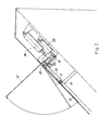
- the rod magazine 2 has a V-shaped bottom surface 3, so that the rods located in the magazine always move towards the center of the magazine by gravity.
- a single bar can be gripped in the magazine 2 and conveyed to the bar feed device of the bending machine.
- gripping devices are generally known and therefore do not need to be described in more detail.
- the gripper 4 pushes the front end of the bar in each case so far into a straight bar guide 5 that it gets into the roller gap between a pair of feed rollers 6 and 7.
- the rollers 6 and 7 each have a circumferential groove and engage positively over the rod.
- the roller 6- is a drive roller which can be driven by a motor in the direction of the arrow P3, the roller 7, which can be adjusted by means of a hydraulic or pneumatic working cylinder 8 against the drive roller 6 or against the rod located between it and the drive roller 6 and can be removed from it , is a towed role that can be connected to a pulse generator in a known manner and can thus also serve as a measuring role.
- the bending tool 11 is preferably designed in accordance with AT-B-314 319 so that the bending mandrel and the movable bending jaw are withdrawn from the rod feed path for changing the direction of the bending process and can be returned to the working position in reversed relative positions with respect to this path, as is the case here has been indicated by the tool position 11 '.
- the scissors 10 can be operated by a working cylinder 12 in the sense of a cut.
- Aii & machine parts with the exception of the scissors 10 and the bending tool 11, are, as can be seen in FIG. 2, covered with a cover plate 15 which can be brought into an opening position 15 'for inspection purposes and then closed again by means of a working cylinder 16.
- the lower sides of the rod guides 5 and 9 are formed by machine-controlled sheet metal strips 17, whereas the remaining three sides of these rod guides are attached to the ends of levers 18, which also serve as rod ejectors and are connected in a rotationally fixed manner to a width 23, by which the cover plate is also connected 15 is pivotally mounted.
- the shaft 23 can be pivoted about its axis by a working cylinder 20 by means of a lever 19.
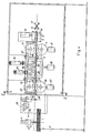
- FIGS. 3 and 4 show a machine which is suitable both for loading with rod material in the form of straight rods of a predetermined length and for loading with rod material of very long length wound into rings.
- This machine has a second pair of feed rollers 25, 26, in which both rollers can be driven by a motor and the roller 26 can be adjusted against the roller 25 by means of a working cylinder 27 or can be removed from this roller, rod guides 28, 29, the structure and method of operation of which are completely the same like that of the staves 5 and 9, complete this additional drive mechanism.
- a structural unit 34 is provided, which by means of a working cylinder 35 between two. Limit positions adjustable, can be moved in the illustrated embodiment.
- a straightening roller set 36 lies in the material feed path.
- a straight rod guide 37 lies in the material feed path.
- the rod guide 37 consists of a guide trough which is closed on three sides and open towards the viewer and which is closed on the open side only by the cover plate 15. As a result of this design, the rod resting in the rod guide 37 can emerge unhindered from the rod guides 5, 9, 28, 29 and also out of the guide 37 when the levers 18, which also act as rod ejectors, are actuated.
- a second straightening roller set 38 is provided according to FIG. 5, which is brought into its working position (in FIGS. 3 and 5 with a working cylinder 39) drawn full lines) or from this working position to its rest position (shown in dashed lines in Figures 4 and 5) can be pivoted.
- the working cylinders 35, 39 are connected in parallel in a common pressure medium line, as a result of which the machine can be converted in a single changeover step either to the supply of elongated rods which have already been aligned or to the supply of rods which have been removed from rings and which are still to be straightened.
- roller groups of each of the two straightening roller sets which are arranged in two parallel planes, can moreover be separated from one another by means which are not shown because generally known means, in order to make it easier to insert the rod into the machine or to remove it from the machine.
Claims (4)
Applications Claiming Priority (2)
| Application Number | Priority Date | Filing Date | Title |
|---|---|---|---|
| AT644479A AT365484B (de) | 1979-10-02 | 1979-10-02 | Einrichtung zum automatischen zufuehren von stabmaterial zu einer biegemaschine fuer betonbewehrungsbuegel |
| AT6444/79 | 1979-10-02 |
Publications (2)
| Publication Number | Publication Date |
|---|---|
| EP0027106A1 EP0027106A1 (fr) | 1981-04-15 |
| EP0027106B1 true EP0027106B1 (fr) | 1983-01-26 |
Family
ID=3586371
Family Applications (1)
| Application Number | Title | Priority Date | Filing Date |
|---|---|---|---|
| EP19800890111 Expired EP0027106B1 (fr) | 1979-10-02 | 1980-10-01 | Dispositif pour amener automatiquement du matériau en tiges à une machine à cintrer des brides d'armature de béton |
Country Status (3)
| Country | Link |
|---|---|
| EP (1) | EP0027106B1 (fr) |
| AT (1) | AT365484B (fr) |
| DE (1) | DE3061796D1 (fr) |
Cited By (1)
| Publication number | Priority date | Publication date | Assignee | Title |
|---|---|---|---|---|
| CN105436362A (zh) * | 2015-11-18 | 2016-03-30 | 天津市银鹤金属制品有限公司 | 步进式水平移料装置 |
Families Citing this family (4)
| Publication number | Priority date | Publication date | Assignee | Title |
|---|---|---|---|---|
| FR2525505A1 (fr) * | 1982-04-21 | 1983-10-28 | Bentzmann Bertrand De | Dispositif de production et d'evacuation de pieces en fil, faconnees |
| IT1295107B1 (it) † | 1997-04-29 | 1999-04-30 | Piegatrici Macch Elettr | Sistema di piegatura perfezionato per macchine piegatrici |
| DK2720814T3 (en) * | 2011-06-15 | 2018-07-23 | Enkotec As | SYSTEM INCLUDING A LEADING DEVICE |
| CN105414416B (zh) * | 2015-12-15 | 2018-12-04 | 芜湖文青机械设备设计有限公司 | 全自动打包钢丝制扣机 |
Family Cites Families (7)
| Publication number | Priority date | Publication date | Assignee | Title |
|---|---|---|---|---|
| DE1243952B (de) * | 1957-06-21 | 1967-07-06 | Fritz Zur Heide | Vorrichtung zum Herstellen von Formbiegeteilen |
| DE1167783B (de) * | 1960-08-12 | 1964-04-16 | Baustahlgewebe Gmbh | Laengsstabzufuehrungseinrichtung fuer Drahtmatten-Schweissmaschinen |
| DE1752693A1 (de) * | 1967-07-05 | 1971-03-18 | Mash Zd Mir | Automat mit Elektroprogrammsteuerung fuer die Erzeugung von Buegeln und Bewehrungselementen |
| BE791166A (fr) * | 1972-04-12 | 1973-03-01 | Evg Entwicklung Verwert Ges | Pileuse pour fil ou bande metallique |
| CA982459A (en) * | 1972-11-14 | 1976-01-27 | William T. Arnold | Apparatus for straightening and cutting reinforcing bar |
| BE835207A (fr) * | 1974-11-08 | 1976-03-01 | Perfectionnements apportes aux machines de forgeage ou analogues | |
| AT345065B (de) * | 1976-03-25 | 1978-08-25 | Evg Entwicklung Verwert Ges | Automatische steuereinrichtung fuer eine zur herstellung von betonbewehrungsbuegeln aus stab- oder drahtmaterial bestimmte biegemaschine |
-
1979
- 1979-10-02 AT AT644479A patent/AT365484B/de active
-
1980
- 1980-10-01 DE DE8080890111T patent/DE3061796D1/de not_active Expired
- 1980-10-01 EP EP19800890111 patent/EP0027106B1/fr not_active Expired
Cited By (1)
| Publication number | Priority date | Publication date | Assignee | Title |
|---|---|---|---|---|
| CN105436362A (zh) * | 2015-11-18 | 2016-03-30 | 天津市银鹤金属制品有限公司 | 步进式水平移料装置 |
Also Published As
| Publication number | Publication date |
|---|---|
| DE3061796D1 (en) | 1983-03-03 |
| EP0027106A1 (fr) | 1981-04-15 |
| AT365484B (de) | 1982-01-25 |
| ATA644479A (de) | 1981-06-15 |
Similar Documents
| Publication | Publication Date | Title |
|---|---|---|
| DE3702223C2 (fr) | ||
| DE3010923A1 (de) | Verfahren zum kontinuierlichen verarbeiten von stahlstaeben fuer bewehrten beton und vorrichtung zur durchfuehrung des verfahrens | |
| DE1527608B2 (de) | Rohrwalzwerk | |
| DE1805322B2 (de) | Bindemaschine | |
| EP0027106B1 (fr) | Dispositif pour amener automatiquement du matériau en tiges à une machine à cintrer des brides d'armature de béton | |
| DE1527444A1 (de) | Verfahren und Vorrichtung zum Verbinden der Enden hintereinander laufender Metallbaender | |
| DE2620190B2 (de) | Elektrische Widerstands-Stumpfschweißmaschine | |
| DE2843531C2 (de) | Maschine zum Herstellen von gitterträgerartigen Bewehrungsgebilden für Stahlbeton | |
| DE69307461T3 (de) | Anlage zum Herstellen von Produkten aus drahtförmigem Material | |
| DE2849751C2 (de) | Vorrichtung zum Vereinzeln von ein loses Bündel bildenden abgelängten Drähten, insbesondere zwechs Drahtzufuhr zu einer Verarbeitungsmaschine | |
| DE60220445T2 (de) | Biegevorrichtung für profile wie rundbetonstahlstäbe oder ähnliche | |
| DE2612304C3 (de) | Biegemaschine für stabförmiges Material, insbesondere für Betonbewehrungsstäbe | |
| DE2917305C2 (de) | Verfahren zur Beseitigung des Vorder- und Hinterabschnitts von Walzdraht und Vorrichtung zur Durchführung des Verfahrens | |
| DE2729624C2 (de) | Verfahren und Fertigungsstraße zum automatischen Herstellen von gebogenen Bestandteilen von Drahtrahmen, insbesondere von inneren Rahmenteilen von Kraftfahrzeugsitzen o.dgl. | |
| DE1914647C3 (de) | Zuführvorrichtung für stangen- oder rohrförmige Werkstücke in eine Richtmaschine | |
| EP0414061B1 (fr) | Dispositif pour retirer une barre métallique d'un faisceau de barres | |
| DE2915716C2 (de) | Verfahren zur Beseitigung des Vorder- und Hinterabschnitts von Walzdraht und Vorrichtung zur Durchführung des Verfahrens | |
| DE3424439A1 (de) | Richtvorrichtung | |
| AT406555B (de) | Anlage zum abschneiden mehrerer drahtlängen von einem drahtmaterialstrang | |
| EP1348571B1 (fr) | Dispositif pour relier des éléments plats empilés | |
| DE1452340A1 (de) | Verfahren und Vorrichtung zum Schneiden von stranggepressten Materialien auf einer Metallstrangpresse mit bewegbarem Behaelter | |
| DE2235120C3 (de) | Stabschneidemaschine zum automatischen Zuschneiden von Bewehrungsstählen | |
| DE3338096A1 (de) | Verfahren und vorrichtung zum ablaengen von metallenen langformguetern | |
| DE3118439C1 (de) | Einrichtung an Kettelmaschinen | |
| DE2550044C2 (de) | Gitterschweißmaschine für Betonstahlmatten |
Legal Events
| Date | Code | Title | Description |
|---|---|---|---|
| PUAI | Public reference made under article 153(3) epc to a published international application that has entered the european phase |
Free format text: ORIGINAL CODE: 0009012 |
|
| AK | Designated contracting states |
Designated state(s): DE FR GB IT |
|
| 17P | Request for examination filed |
Effective date: 19810314 |
|
| ITF | It: translation for a ep patent filed |
Owner name: BARZANO' E ZANARDO MILANO S.P.A. |
|
| GRAA | (expected) grant |
Free format text: ORIGINAL CODE: 0009210 |
|
| AK | Designated contracting states |
Designated state(s): DE FR GB IT |
|
| REF | Corresponds to: |
Ref document number: 3061796 Country of ref document: DE Date of ref document: 19830303 |
|
| ET | Fr: translation filed | ||
| PLBI | Opposition filed |
Free format text: ORIGINAL CODE: 0009260 |
|
| 26 | Opposition filed |
Opponent name: MUHR UND BENDER Effective date: 19830505 |
|
| PLBN | Opposition rejected |
Free format text: ORIGINAL CODE: 0009273 |
|
| STAA | Information on the status of an ep patent application or granted ep patent |
Free format text: STATUS: OPPOSITION REJECTED |
|
| 27O | Opposition rejected |
Effective date: 19870409 |
|
| PGFP | Annual fee paid to national office [announced via postgrant information from national office to epo] |
Ref country code: FR Payment date: 19890929 Year of fee payment: 10 |
|
| PGFP | Annual fee paid to national office [announced via postgrant information from national office to epo] |
Ref country code: GB Payment date: 19890930 Year of fee payment: 10 |
|
| PGFP | Annual fee paid to national office [announced via postgrant information from national office to epo] |
Ref country code: DE Payment date: 19891228 Year of fee payment: 10 |
|
| PG25 | Lapsed in a contracting state [announced via postgrant information from national office to epo] |
Ref country code: GB Effective date: 19901001 |
|
| ITTA | It: last paid annual fee | ||
| GBPC | Gb: european patent ceased through non-payment of renewal fee | ||
| PG25 | Lapsed in a contracting state [announced via postgrant information from national office to epo] |
Ref country code: FR Effective date: 19910628 |
|
| PG25 | Lapsed in a contracting state [announced via postgrant information from national office to epo] |
Ref country code: DE Effective date: 19910702 |
|
| REG | Reference to a national code |
Ref country code: FR Ref legal event code: ST |