EP0027106B1 - Device for the automatic feeding of rod stock to a bending machine for concrete-reinforcement stirrups - Google Patents
Device for the automatic feeding of rod stock to a bending machine for concrete-reinforcement stirrups Download PDFInfo
- Publication number
- EP0027106B1 EP0027106B1 EP19800890111 EP80890111A EP0027106B1 EP 0027106 B1 EP0027106 B1 EP 0027106B1 EP 19800890111 EP19800890111 EP 19800890111 EP 80890111 A EP80890111 A EP 80890111A EP 0027106 B1 EP0027106 B1 EP 0027106B1
- Authority
- EP
- European Patent Office
- Prior art keywords
- rod
- rolls
- bending
- feed
- thrower
- Prior art date
- Legal status (The legal status is an assumption and is not a legal conclusion. Google has not performed a legal analysis and makes no representation as to the accuracy of the status listed.)
- Expired
Links
Images


Classifications
-
- B—PERFORMING OPERATIONS; TRANSPORTING
- B21—MECHANICAL METAL-WORKING WITHOUT ESSENTIALLY REMOVING MATERIAL; PUNCHING METAL
- B21F—WORKING OR PROCESSING OF METAL WIRE
- B21F23/00—Feeding wire in wire-working machines or apparatus
- B21F23/005—Feeding discrete lengths of wire or rod
-
- B—PERFORMING OPERATIONS; TRANSPORTING
- B21—MECHANICAL METAL-WORKING WITHOUT ESSENTIALLY REMOVING MATERIAL; PUNCHING METAL
- B21D—WORKING OR PROCESSING OF SHEET METAL OR METAL TUBES, RODS OR PROFILES WITHOUT ESSENTIALLY REMOVING MATERIAL; PUNCHING METAL
- B21D43/00—Feeding, positioning or storing devices combined with, or arranged in, or specially adapted for use in connection with, apparatus for working or processing sheet metal, metal tubes or metal profiles; Associations therewith of cutting devices
- B21D43/006—Feeding elongated articles, such as tubes, bars, or profiles
-
- B—PERFORMING OPERATIONS; TRANSPORTING
- B21—MECHANICAL METAL-WORKING WITHOUT ESSENTIALLY REMOVING MATERIAL; PUNCHING METAL
- B21F—WORKING OR PROCESSING OF METAL WIRE
- B21F23/00—Feeding wire in wire-working machines or apparatus
- B21F23/005—Feeding discrete lengths of wire or rod
- B21F23/007—Feeding discrete lengths of wire or rod using pick-up means, e.g. for isolating a predefined number of wires from a bundle
Definitions
- the invention relates to a device according to the preamble of claim 1 for automatically feeding rod material to a bending machine for concrete reinforcement stirrups.
- the cut-to-length rod pieces are normally fed to a processing device by means of a gripper, but are thrown off at the beginning and at the end of each rod to remove the uneven end sections of the rod material from the gripper, which temporarily acts as a rod ejector, perpendicular to the rod axis.
- stirrups are to be made from rod material that is available in standard lengths - usually 12 to 14 m - the accumulation of remnants is unavoidable, because the standard length of a rod generally does not correspond to the sum of the unwound lengths of the stirrups made one after the other from the rod .
- the bending machine In order to work efficiently and to be able to produce the stirrups economically, the bending machine must be able to be automatically loaded with the required rods, which are taken from a rod magazine, and must also be equipped with an electronic computer, which measures the lengths of the individual feed steps of the rod material between successive bending stages , the sense of direction and the size of the bending angle and finally also the available bar length must be entered. On the basis of these input data, the computer can then determine when the remaining length of a bar is no longer sufficient to produce another bracket and must therefore be removed from the machine.
- the feed rollers Due to the design dimensions of the feed rollers, the scissors and the bending device, the feed rollers are always arranged at a distance from the actual bending device. It follows immediately that the bending process must be ended at the latest when the end of the remaining remnant is just being gripped by the feed rollers, or in other words when the minimum length of the remnant is equal to the vertical distance of the pivot axis of the bending tool from that through the axes of the Feed rollers defined level is. If this length of the remaining piece is reached, then a further, controlled feeding of the remaining piece to the bending unit is no longer possible, but the remaining piece can still be removed from the bending machine by reversing the direction of rotation of the feed rollers in the direction opposite to its normal feed direction.
- the minimum length of the remnants must be greater than the value specified above, by such an amount that it is still possible to accelerate the remnant by rapidly driving the feed rollers so that its rear end due to the remnant at Acceleration given the impulse between the feed rollers and the Bending tool can go through.
- the invention is concerned with the task of designing a device of the type specified in the introduction which is suitable for the automatic feeding of rod material to a bending machine in such a way that the minimum length of unusable remaining pieces is as short as possible and that further removal of long remaining pieces from the bending machine is possible without this can either get back into the rod magazine or injure people in front of the bending machine.
- the cut-to-length rod pieces regardless of whether they are rod pieces for further processing, end products or waste, are removed from the rod feed path in a lateral direction behind the scissors
- the remaining pieces resulting from bow bending machines are removed in the area the feed rollers lying in front of the scissors are ejected laterally, for which the roller gap is enlarged accordingly and the rod guides provided in this area are opened laterally.
- the remnants ejected laterally in front of the scissors cannot mix with the finished stirrups behind the scissors; they can therefore be easily collected and they can be ejected without considerable effort, so that there is no risk of injury to the operating personnel required at the front end of the machine.
- the remaining pieces can be kept very short in order to minimize material losses.
- Embodiments of the invention result from the dependent claims 2 to 4.
- the rod magazine 2 has a V-shaped bottom surface 3, so that the rods located in the magazine always move towards the center of the magazine by gravity.
- a single bar can be gripped in the magazine 2 and conveyed to the bar feed device of the bending machine.
- gripping devices are generally known and therefore do not need to be described in more detail.
- the gripper 4 pushes the front end of the bar in each case so far into a straight bar guide 5 that it gets into the roller gap between a pair of feed rollers 6 and 7.
- the rollers 6 and 7 each have a circumferential groove and engage positively over the rod.
- the roller 6- is a drive roller which can be driven by a motor in the direction of the arrow P3, the roller 7, which can be adjusted by means of a hydraulic or pneumatic working cylinder 8 against the drive roller 6 or against the rod located between it and the drive roller 6 and can be removed from it , is a towed role that can be connected to a pulse generator in a known manner and can thus also serve as a measuring role.
- the bending tool 11 is preferably designed in accordance with AT-B-314 319 so that the bending mandrel and the movable bending jaw are withdrawn from the rod feed path for changing the direction of the bending process and can be returned to the working position in reversed relative positions with respect to this path, as is the case here has been indicated by the tool position 11 '.
- the scissors 10 can be operated by a working cylinder 12 in the sense of a cut.
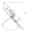
- Aii & machine parts with the exception of the scissors 10 and the bending tool 11, are, as can be seen in FIG. 2, covered with a cover plate 15 which can be brought into an opening position 15 'for inspection purposes and then closed again by means of a working cylinder 16.
- the lower sides of the rod guides 5 and 9 are formed by machine-controlled sheet metal strips 17, whereas the remaining three sides of these rod guides are attached to the ends of levers 18, which also serve as rod ejectors and are connected in a rotationally fixed manner to a width 23, by which the cover plate is also connected 15 is pivotally mounted.
- the shaft 23 can be pivoted about its axis by a working cylinder 20 by means of a lever 19.
- FIGS. 3 and 4 show a machine which is suitable both for loading with rod material in the form of straight rods of a predetermined length and for loading with rod material of very long length wound into rings.
- This machine has a second pair of feed rollers 25, 26, in which both rollers can be driven by a motor and the roller 26 can be adjusted against the roller 25 by means of a working cylinder 27 or can be removed from this roller, rod guides 28, 29, the structure and method of operation of which are completely the same like that of the staves 5 and 9, complete this additional drive mechanism.
- a structural unit 34 is provided, which by means of a working cylinder 35 between two. Limit positions adjustable, can be moved in the illustrated embodiment.
- a straightening roller set 36 lies in the material feed path.
- a straight rod guide 37 lies in the material feed path.
- the rod guide 37 consists of a guide trough which is closed on three sides and open towards the viewer and which is closed on the open side only by the cover plate 15. As a result of this design, the rod resting in the rod guide 37 can emerge unhindered from the rod guides 5, 9, 28, 29 and also out of the guide 37 when the levers 18, which also act as rod ejectors, are actuated.
- a second straightening roller set 38 is provided according to FIG. 5, which is brought into its working position (in FIGS. 3 and 5 with a working cylinder 39) drawn full lines) or from this working position to its rest position (shown in dashed lines in Figures 4 and 5) can be pivoted.
- the working cylinders 35, 39 are connected in parallel in a common pressure medium line, as a result of which the machine can be converted in a single changeover step either to the supply of elongated rods which have already been aligned or to the supply of rods which have been removed from rings and which are still to be straightened.
- roller groups of each of the two straightening roller sets which are arranged in two parallel planes, can moreover be separated from one another by means which are not shown because generally known means, in order to make it easier to insert the rod into the machine or to remove it from the machine.
Description
Die Erfindung betrifft eine Einrichtung nach dem Oberbegriff von Anspruch 1 zum automatischen Zuführen von Stabmaterial zu einer Biegemaschine für Betonbewehrungsbügel.The invention relates to a device according to the preamble of claim 1 for automatically feeding rod material to a bending machine for concrete reinforcement stirrups.
Aus der DE-A1-2549546 ist es bekannt, bei Werkzeugmaschinen, denen axial aufeinander ausgerichtete Stäbe mit ihren Enden aneinanderstoßend als Rohmaterial zugeführt werden und in denen von diesen Stäben Stücke abgelängt und weiterverarbeitet werden, für den Vorschub das Stabmaterial formschlüssig übergreifende Vorschubrollen vorzusehen, deren Rollenspalt beim Durchlauf der Stoßenden zweier aufeinanderfolgender Stäbe zur Erleichterung des Eintrittes des Vorderendes des hinteren Stabes jeweils kurzzeitig vergrößert wird, und zwar unter der Steuerwirkung einer federnd gegen das Stabmaterial gedrückten Abtastrolle, die beim Übergang vom Ende des vorderen Stabes auf den Anfang des hinteren Stabes eine Abtastbewegung ausführt. Die abgelängten Stabstücke werden normalerweise mittels eines Greifers einer Verarbeitungsvorrichtung zugeführt, am Anfang und am Ende jedes Stabes aber zwecks Beseitigung der ungleichmäßigen Endabschnitte des Stabmaterials von dem zeitweilig als Stabauswerfer wirkenden Greifer senkrecht zur Stabachse abgeworfen.From DE-A1-2549546 it is known in machine tools, to which axially aligned rods are fed with their ends abutting against one another as raw material and in which pieces of these rods are cut to length and further processed, to provide the rod material with positive interlocking feed rollers for the feed, their The roller gap when the butt ends of two successive rods pass through is briefly increased in each case to facilitate the entry of the front end of the rear rod, under the control effect of a scanning roller pressed resiliently against the rod material, which acts as a transition from the end of the front rod to the beginning of the rear rod Executes scanning movement. The cut-to-length rod pieces are normally fed to a processing device by means of a gripper, but are thrown off at the beginning and at the end of each rod to remove the uneven end sections of the rod material from the gripper, which temporarily acts as a rod ejector, perpendicular to the rod axis.
Ferner ist aus der US-A-3 916 662 eine kombinierte Richt- und Schneidvorrichtung für Bewehrungsstahl bekannt, bei welcher Stabmaterial mit Hilfe von Vorschubrollen von einem Ring abgezogen und durch hintereinander angeordnete Richtsätze hindurchgeführt wird ; mittels einer von einer Längenmeßeinrichung gesteuerten, zwischen zwei Vorschubrollenpaaren angeordneten rotierenden Schere wird das geradegerichtete Stabmaterial in gewünschte Abschnitte abgelängt und diese Abschnitte werden sodann auf einen von schwenkbaren Armen gebildeten Rechen aufgeschoben, von dem sie nach Erreichen einer gewünschten Stückzahl senkrecht zur Stablängsachse in eine Auffangvorrichtung abgeworfen werden.Furthermore, from US-A-3 916 662 a combined straightening and cutting device for reinforcing steel is known, in which rod material is drawn off from a ring with the aid of feed rollers and passed through straightening sets arranged one behind the other; By means of a rotating shear controlled by a length measuring device and arranged between two pairs of feed rollers, the straightened rod material is cut to desired sections and these sections are then pushed onto a rake formed by pivotable arms, from which they are thrown into a collecting device perpendicular to the longitudinal axis of the bar after a desired number of pieces has been reached will.
Andere Probleme als bei diesen bekannten Werkzeugmaschinen ergeben sich bei Bügelbiegemaschinen. Sollen nämlich Bügel aus Stabmaterial hergestellt werden, das in Standardlängen - zumeist 12 bis 14 m - verfügbar ist, so ist das Anfallen von Reststücken unvermeidlich, weil die Standardlänge eines Stabes im allgemeinen nicht der Summe der abgewickelten Längen der nacheinander aus dem Stab gefertigten Bügel entspricht.Problems other than these known machine tools arise with bow bending machines. If stirrups are to be made from rod material that is available in standard lengths - usually 12 to 14 m - the accumulation of remnants is unavoidable, because the standard length of a rod generally does not correspond to the sum of the unwound lengths of the stirrups made one after the other from the rod .
Um rationell arbeiten und die Bügel wirtschaftlich fertigen zu können, muß die Biegemaschine mit den erforderlichen Stäben, die aus einem Stabmagazin entnommen werden, automatisch beschickt werden können und überdies mit einem elektronischen Rechner ausgestattet sein, dem die Längen der einzelnen Vorschubschritte des Stabmaterials zwischen aufeinanderfolgenden Biegeschritten, der Richtungssinn und die Größe der Biegewinkel und schließlich auch noch die verfügbare Stablänge eingegeben werden müssen. Aufgrund dieser Eingabedaten kann der Rechner dann feststellen, wann die verbleibende Restlänge eines Stabes nicht mehr zur Fertigung eines weiteren Bügels ausreicht und daher aus der Maschine entfernt werden muß.In order to work efficiently and to be able to produce the stirrups economically, the bending machine must be able to be automatically loaded with the required rods, which are taken from a rod magazine, and must also be equipped with an electronic computer, which measures the lengths of the individual feed steps of the rod material between successive bending stages , the sense of direction and the size of the bending angle and finally also the available bar length must be entered. On the basis of these input data, the computer can then determine when the remaining length of a bar is no longer sufficient to produce another bracket and must therefore be removed from the machine.
Zwischen den Vorschubrollen für das Stabmaterial und der eigentlichen Biegeeinrichtung ist bei Bügelbiegemaschinen eine Schere angeordnet, mit deren Hilfe jeder fertig gebogene Bügel vom verbleibenden Stabmaterial abgetrennt werden kann.In the case of bow bending machines, a pair of scissors is arranged between the feed rollers for the bar material and the actual bending device, with the aid of which each finished bow can be separated from the remaining bar material.
Zufolge der konstruktiv notwendigen Abmessungen der Vorschubrollen, der Schere und der Biegeeinrichtung sind die Vorschubrollen stets in einem Abstand von der eigentlichen Biegeeinrichtung angeordnet. Daraus folgt unmittelbar, daß der Biegevorgang spätestens dann beendet werden muß, wenn das Ende der verbleibenden Reststückes gerade noch von den Vorschubrollen erfaßt wird, oder anders ausgedrückt, wenn die Mindestlänge des Reststückes gleich dem senkrechten Abstand der Schwenkachse des Biegewerkzeuges von der durch die Achsen der Vorschubrollen definierten Ebene ist. Ist diese Länge des Reststückes erreicht, dann ist ein weiteres, kontrolliertes Vorschieben des Reststückes zur Biegeeinheit nicht mehr möglich, wohl aber kann das Reststück durch Umkehr der Drehrichtung der Vorschubrollen noch in zu seiner normalen Vorschubrichtung entgegengesetzter Richtung aus der Biegemaschine entfernt werden.Due to the design dimensions of the feed rollers, the scissors and the bending device, the feed rollers are always arranged at a distance from the actual bending device. It follows immediately that the bending process must be ended at the latest when the end of the remaining remnant is just being gripped by the feed rollers, or in other words when the minimum length of the remnant is equal to the vertical distance of the pivot axis of the bending tool from that through the axes of the Feed rollers defined level is. If this length of the remaining piece is reached, then a further, controlled feeding of the remaining piece to the bending unit is no longer possible, but the remaining piece can still be removed from the bending machine by reversing the direction of rotation of the feed rollers in the direction opposite to its normal feed direction.
Nun ist ein derartiges Zurückschieben der Reststücke in Richtung auf das Stabmagazin ungünstig, weil bei langen Reststücken, das sind Stücke, deren Länge größer als der vorhin angegebene Mindestwert, aber kleiner als die um die abgewickelte Länge eines Bügels verminderte Standardlänge eines Stabes ist, die Möglichkeit besteht, daß das Reststück wieder zurück in das Stabmagazin gelangt und von dort neuerlich der Maschine zugeführt wird. Wenn die Biegemaschine jedoch auf die Zufuhr von Stäben mit Standardlänge programmiert ist, würde beim Zuführen eines kürzeren Reststückes der Programmablauf der Biegemaschine empfindlich gestört werden.Such a pushing back of the remaining pieces in the direction of the rod magazine is unfavorable, because with long remaining pieces, that is pieces whose length is greater than the minimum value specified above, but smaller than the standard length of a rod reduced by the unwound length of a bracket, the possibility exists there is that the remainder gets back into the rod magazine and is fed from there again to the machine. However, if the bending machine is programmed to feed bars of standard length, the program sequence of the bending machine would be disturbed considerably when a shorter remnant was fed.
Eine andere Möglichkeit besteht darin, das Reststück in Richtung auf das Biegewerkzeug aus der Biegemaschine zu entfernen. Dazu muß aber die Mindestlänge der Reststücke größer als der vorhin angegebene Wert sein, und zwar um einen solchen Betrag, daß es noch möglich ist, das Reststück durch schnelles Antreiben der Vorschubrollen so stark zu beschleunigen, daß sein rückwärtiges Ende aufgrund des dem Reststück bei der Beschleunigung erteilten Impulses den Weg zwischen den Vorschubrollen und dem Biegewerkzeug durchlaufen kann.Another possibility is to remove the remnant from the bending machine in the direction of the bending tool. To do this, however, the minimum length of the remnants must be greater than the value specified above, by such an amount that it is still possible to accelerate the remnant by rapidly driving the feed rollers so that its rear end due to the remnant at Acceleration given the impulse between the feed rollers and the Bending tool can go through.
Bei dieser Vorgangsweise ist die Menge des anfallenden, nicht mehr verwertbaren Materials erheblich größer als im ersten Falle, und es besteht überdies die Gefahr, daß die mit erheblicher Geschwindigkeit aus der Biegemaschine ausgestoßenen Reststücke sich zufällig vor der Biegemaschine befindende Personen verletzen.With this procedure, the amount of accumulated, no longer usable material is considerably larger than in the first case, and there is also the risk that the remaining pieces expelled from the bending machine at considerable speed injure people accidentally in front of the bending machine.
Die Erfindung befaßt sich mit der Aufgabe, eine zum automatischen Zuführen von Stabmaterial zu einer Biegemaschine geeignete Einrichtung der einleitend angegebenen Gattung so auszubilden, daß die Mindestlänge unverwertbarer Reststücke möglichst gering wird und daß ferner ein Entfernen langer Reststücke aus der Biegemaschine möglich ist, ohne daß diese entweder wieder in das Stabmagazin gelangen oder sich vor der Biegemaschine befindende Personen verletzen können.The invention is concerned with the task of designing a device of the type specified in the introduction which is suitable for the automatic feeding of rod material to a bending machine in such a way that the minimum length of unusable remaining pieces is as short as possible and that further removal of long remaining pieces from the bending machine is possible without this can either get back into the rod magazine or injure people in front of the bending machine.
Diese Aufgabe ist gemäß den Kennzeichnungsmerkmalen von Anspruch 1 gelöst.This object is achieved in accordance with the characterizing features of claim 1.
Während bei den einleitend geschilderten bekannten Werkzeugmaschinen die abgelängten Stabstücke, unabhängig davon, ob es sich um Stabstücke zur Weiterverarbeitung, um Endprodukte oder um Abfall handelt, hinter der Schere in seitlicher Richtung aus der Stabvorschubbahn entfernt werden, werden erfindungsgemäß die bei Bügelbiegemaschinen anfallenden Reststücke im Bereich der vor der Schere liegenden Vorschubrollen seitlich ausgeworfen, wozu der Rollenspalt entsprechend vergrößert und die in diesem Bereich vorgesehenen Stabführungen seitlich geöffnet werden. Die seitlich vor der Schere ausgeworfenen Reststücke können sich nicht mit den hinter der Schere anfallenden fertigen Bügeln vermischen ; sie können daher leicht eingesammelt werden und ihr Auswurf kann ohne wesentlichen Kraftaufwand erfolgen, so daß keine Verletzungsgefahr für das am Vorderende der Maschine erforderliche Bedienungspersonal besteht. Überdies können die Reststücke sehr kurz gehalten werden, um die Materialverluste zu minimieren.While in the known machine tools described in the introduction, the cut-to-length rod pieces, regardless of whether they are rod pieces for further processing, end products or waste, are removed from the rod feed path in a lateral direction behind the scissors, according to the invention, the remaining pieces resulting from bow bending machines are removed in the area the feed rollers lying in front of the scissors are ejected laterally, for which the roller gap is enlarged accordingly and the rod guides provided in this area are opened laterally. The remnants ejected laterally in front of the scissors cannot mix with the finished stirrups behind the scissors; they can therefore be easily collected and they can be ejected without considerable effort, so that there is no risk of injury to the operating personnel required at the front end of the machine. In addition, the remaining pieces can be kept very short in order to minimize material losses.
Ausgestaltungen der Erfindung ergeben sich aus den abhängigen Ansprüchen 2 bis 4.Embodiments of the invention result from the
Die Erfindung wird nun anhand von Ausführungsbeispielen unter Bezugnahme auf die Zeichnungen genauer beschrieben. Es zeigt
- Figur 1 eine mit einer Einrichtung nach der Erfindung ausgestattete Bügelbiegemaschine in Ansicht, wobei der bevorzugt schräg angeordnete Biegeteil aus Gründen der Einfachheit der Darstellung in die Zeichenebene gedreht dargestellt ist,
Figur 2 einen Schnitt nach der Linie 11-11 in Figur 1, der die bevorzugte Schräglage des Biegetisches erkennen läßt,Figur 3 die Ansicht einer Bügelbiegemaschine, die mit einer Einrichtung zum wahlweisen Zuführen von Stabmaterial in Form von abgelängten, geraden Stäben oder von Ringen ausgestattet ist, in der Arbeitsstellung für Materialzufuhr von Ringen, wobei wieder der bevorzugt schräg angeordnete Biegeteil aus Gründen der Einfachheit der Darstellung in die Zwischenebene gedreht dargestellt ist,Figur 4 eine andere Darstellung der Maschine nach Figur3, jedoch in der Arbeitsstellung für das Zuführen von abgelängten, geraden Stäben,Figur 5 einen Schnitt nach der Linie V-V in Figur4, der wieder die bevorzugte Schräglage des Biegetisches erkennen läßt.
- 1 shows a stirrup bending machine equipped with a device according to the invention, the preferably obliquely arranged bent part being shown rotated into the plane of the drawing for reasons of simplicity of illustration,
- FIG. 2 shows a section along line 11-11 in FIG. 1, which shows the preferred inclined position of the bending table,
- Figure 3 is a view of a stirrup bending machine, which is equipped with a device for the optional feeding of rod material in the form of cut, straight rods or rings, in the working position for material feeding of rings, again the preferably obliquely arranged bending part for reasons of simplicity of illustration is shown rotated to the intermediate level,
- FIG. 4 shows another illustration of the machine according to FIG. 3, but in the working position for feeding cut, straight bars,
- Figure 5 is a section along the line VV in Figure 4, which again shows the preferred inclined position of the bending table.
In Figur 1 erkennt man gerade, abgelängte Stäbe 1, die in einem Stabmagazin 2 ruhen. Wie insbesondere aus Figur erkennbar ist, hat das Stabmagazin 2 eine V-förmige Bodenfläche 3, so daß sich die im Magazin befindlichen Stäbe stets durch die .Schwerkraft zur Magazinmitte hin bewegen.1 shows straight, cut-to-length rods 1 which rest in a
Mit Hilfe eines in Richtung der Doppelpfeile P1 und P2 verfahrbaren Greifers 4 kann ein einzelner Stab im Magazin 2 erfaßt und zur Stabzuführungseinrichtung der Biegemaschine hin gefördert werden. Derartige Greifvorrichtungen sind allgemein bekannt und brauchen daher nicht näher beschrieben zu werden.With the aid of a
Der Greifer 4 schiebt in der Stellung 4' das vordere Ende des jeweils erfaßten Stabes zunächst so weit in eine gerade Stabführung 5, daß es in den Rollenspalt zwischen einem Paar von Vorschubrollen 6 und 7 gelangt. Die Rollen 6 und 7 haben je eine Umfangsnut und übergreifen den Stab formschlüssig.In position 4 ', the
Die Rolle 6- ist eine im Sinne des Pfeiles P3 motorisch antreibbare Treibrolle, die Rolle 7, die mittels eines hydraulischen oder pneumatischen Arbeitszylinders 8 gegen die Treibrolle 6 bzw. gegen den zwischen ihr und der Treibrolle 6 befindlichen Stab anstellbar und von diesem wieder entfernbar ist, ist eine geschleppte Rolle, die in bekannter Weise mit einem Impulsgeber verbunden sein und so gleichzeitig als Meßrolle dienen kann.The roller 6- is a drive roller which can be driven by a motor in the direction of the arrow P3, the
Sobald die Meßrolle 7 mittels des Arbeitszylinders 8 gegen den Stab angestellt und die Treibrolle 6 in Richtung des Pfeiles P3 in Drehung versetzt wird, wird der Stab durch eine weitere Stabfürung 9 und zwischen den beiden Messern einer Schere 10 hindurch in das Biegewerkzeug 11 vorgeschoben. Das Biegewerkzeug 11 ist vorzugsweise gemäß der AT-B-314 319 so ausgebildet, daß der Biegedorn und die bewegliche Biegebacke zum Wechsel des Richtungssinnes des Biegevorganges aus der Stabvorschubbahn zurückgezogen und in vertauschten Relativlagen bezüglich dieser Bahn wieder in die Arbeitsstellung zurückgeführt werden können, wie dies durch die Werkzeugstellung 11' angedeutet worden ist. Die Schere 10 kann von einem Arbeitszylinder 12 im Sinne eines Schnittes betätigt werden.As soon as the
Aii& Maschinenteile, mit Ausnahme der Schere 10 und des Biegewerkzeuges 11, sind, wie Figur 2 erkennen läßt, mit einer Abdeckplatte 15, die mittels eines Arbeitszylinders 16 in eine Inspektionszwecken dienende Öffnungslage 15' gebracht und sodann wieder geschlossen werden kann, abgedeckt.Aii & machine parts, with the exception of the
Die unteren Seiten der Stabführungen 5 und 9 sind durch maschinenteste Blechstreifen 17 gebildet, wogegen die übrigen drei Seiten dieser Stabführungen an den Enden von Hebeln 18 befestigt sind, die zugleich als Stabauswerfer dienen und drehfest mit einer Weite 23 verbunden sind, um welche auch die Abdeckplatte 15 schwenkbar gelagert ist. Mittels eines Hebels 19 kann die Welle 23 durch einen Arbeitszylinder 20 um ihre Achse verschwenkt werden.The lower sides of the
Um ein Reststück eines Stabes auswerfen zu können. wird dieses durch die Treibrolle 6 soweit vorgeschoben, bis es zur Gänze in den Stabführungen 5 und 9 ruht. Nun wird mittels des Arbeitszylinders 8 die Meßrolle 7 so weit von der Treibrolle 6 entfernt, daß der Stab durch den vergrÖBerten Rollenspalt seitlich hindurchtreten kann.To be able to eject a remaining piece of a stick. this is advanced by the
Anschließend wird durch Betätigung des Arbeitszylinders 20 mittels des Hebels 19 die Welle 23 verschwenkt und dadurch werden die mit dieser Welle verbundenen Teile der Stabführung in die in Figur 2 strichliert gezeichnete Lage gebracht. Da die Abdeckplatte 15 koexial mit der Wege 23 gelagert ist, nehmen die aus ihrer Ruhelage herausschwenkenden und als Stabauswerfer fungierenden Hebel 18 die Abdeckplatte bei ihrer Bewegung mit und der Stabrest kann aus den nunmehr unten offenen Stabführungen 5 und 9 austreten und längs des schrägstehenden Biegetisches herabgleiten. Gegebenenfalls können noch Fangbleche 24 (Figur 5) vorgesehen sein, in welchen die herabgleitenden Stabreste gesammelt werden.Subsequently, by actuating the working
Die Öffnungsbewegung der Abdeckplatte 15 unter der Wirkung des Arbeitszylinders 20 erfolgt dabei gegen eine begrenzte, durch den Arbeitszylinder 16 ausgeübte Kraft, so daß beim Zurückschwenken der Hebel 18 die Abdeckplatte 15 automatisch durch den Arbeitszylinder 16 wieder geschlossen wird.The opening movement of the
Die Figuren 3 und 4 zeigen eine Maschine, die sowohl für das Beschicken mit Stabmaterial in Form gerader Stangen vorgegebener Länge, als auch für das Beschicken mit zu Ringen aufge- wickeltem Stabmaterial sehr großer Länge geeignet ist.FIGS. 3 and 4 show a machine which is suitable both for loading with rod material in the form of straight rods of a predetermined length and for loading with rod material of very long length wound into rings.
Diese Maschine weist ein zweites Vorschubrollenpaar 25, 26 auf, bei dem beide Rollen motorisch antreibbar sein können und die Rolle 26 mittels eines Arbeitszylinders 27 gegen die Rolle 25 hin anstellbar oder von dieser Rolle entfernbar ist Stabführungen 28, 29, deren Aufbau und Betätigungsweise völlig gleich wie jene der Staführungen 5 und 9 ist, vervollständigen diesen zusätzlichen Antriebsmechanismus.This machine has a second pair of
Zwischen den in gegenseitigem Abstand im Stabrorschbweg angeordneten Rollenpaaren 6, 7 und 25, 26 ist eine Baueinheit 34 vorgesehen, die mittels eines Arbeitszylinders 35 zwischen zwei. Grenzlagen verstellbar, im dargestellten Aushführungsbeispiel verschiebbar ist.Between the pairs of
In der in Figur 3 gezeigten, unteren Grenzlage der Baueinheit 34 liegt ein Richtrollensatz 36 im materialvorschubweg. In der in Figur 4 gezeigten oberen Grenzlage der Baueinheit 34 liegt eine gerade Stabführung 37 im Materialvorschubweg.In the lower limit position of the
Die Stabführung 37 besteht aus einer an drei Seiten geschlossenen, gegen den Betrachter hin offenen Führungsrinne, die auf der offenen Seite lediglich durch die Abdeckplatte 15 geschlossen wird. Zufolge dieser Ausbildung kann der in der Stabführung 37 ruhende Stab bei Betätigung der gleichzeitig als Stabauswerfer wirkenden Hebel 18 ungehindert aus den Stabführungen 5, 9, 28, 29 und auch aus der Führung 37 heraustreten.The
Um den von einem Ring abgezogenen, langen Stab auch in der auf die Wirkungsebene des Richtrollensatzes 36 senkrechten Ebene richten zu können, ist gemäß Figur 5 ein zweiter Richtrollensatz 38 vorgesehen, der mittels eines Arbeitszylinders 39 in seine Arbeitsstellung (in den Figuren 3 und 5 mit vollen Linien gezeichnet) oder aus dieser Arbeitsstellung heraus in seine Ruhestellung (in den Figuren 4 und 5 strichliert gezeichnet) geschwenkt werden kann.In order to be able to straighten the long rod pulled off from a ring also in the plane perpendicular to the plane of action of the straightening
Die Arbeitszylinder 35, 39 liegen in Parallelschaltung in einer gemeinsamen Druckmittelleitung, wodurch die Maschine in einem einzigen Umstellschritt entweder auf Zufuhr bereits gerichteter, abgelänger Stäbe oder auf Zufuhr von von Ringen abgezogener, vorerst noch zu richtender Stäbe umgestellt werden kann.The working
Die in zwei parallelen Ebenen angeordneten Rollengruppen jedes der beiden Richtrollensätze können überdies noch durch nicht dargestellte, weil allgemein bekannte Mittel voneinander entfernt werden, um das Einführen des Stabes in die Maschine oder sein Entfernen aus der Maschine zu erleichtern.The roller groups of each of the two straightening roller sets, which are arranged in two parallel planes, can moreover be separated from one another by means which are not shown because generally known means, in order to make it easier to insert the rod into the machine or to remove it from the machine.
Claims (4)
Applications Claiming Priority (2)
| Application Number | Priority Date | Filing Date | Title |
|---|---|---|---|
| AT644479A AT365484B (en) | 1979-10-02 | 1979-10-02 | DEVICE FOR THE AUTOMATIC FEEDING OF ROD MATERIAL TO A BENDING MACHINE FOR CONCRETE REINFORCEMENT BRACKETS |
| AT6444/79 | 1979-10-02 |
Publications (2)
| Publication Number | Publication Date |
|---|---|
| EP0027106A1 EP0027106A1 (en) | 1981-04-15 |
| EP0027106B1 true EP0027106B1 (en) | 1983-01-26 |
Family
ID=3586371
Family Applications (1)
| Application Number | Title | Priority Date | Filing Date |
|---|---|---|---|
| EP19800890111 Expired EP0027106B1 (en) | 1979-10-02 | 1980-10-01 | Device for the automatic feeding of rod stock to a bending machine for concrete-reinforcement stirrups |
Country Status (3)
| Country | Link |
|---|---|
| EP (1) | EP0027106B1 (en) |
| AT (1) | AT365484B (en) |
| DE (1) | DE3061796D1 (en) |
Cited By (1)
| Publication number | Priority date | Publication date | Assignee | Title |
|---|---|---|---|---|
| CN105436362A (en) * | 2015-11-18 | 2016-03-30 | 天津市银鹤金属制品有限公司 | Stepping type horizontal material moving device |
Families Citing this family (4)
| Publication number | Priority date | Publication date | Assignee | Title |
|---|---|---|---|---|
| FR2525505A1 (en) * | 1982-04-21 | 1983-10-28 | Bentzmann Bertrand De | DEVICE FOR PRODUCING AND EVACUATING WIRED PIECES, MADE |
| IT1295107B1 (en) † | 1997-04-29 | 1999-04-30 | Piegatrici Macch Elettr | BENDING SYSTEM PERFECTED FOR BENDING MACHINES |
| DK2720814T3 (en) * | 2011-06-15 | 2018-07-23 | Enkotec As | SYSTEM INCLUDING A LEADING DEVICE |
| CN105414416B (en) * | 2015-12-15 | 2018-12-04 | 芜湖文青机械设备设计有限公司 | Full-automatic bale tie wire deduction |
Family Cites Families (7)
| Publication number | Priority date | Publication date | Assignee | Title |
|---|---|---|---|---|
| DE1243952B (en) * | 1957-06-21 | 1967-07-06 | Fritz Zur Heide | Device for the production of shaped bent parts |
| DE1167783B (en) * | 1960-08-12 | 1964-04-16 | Baustahlgewebe Gmbh | Laengsstabzufuehrungseinrichtung for wire mesh welding machines |
| DE1752693A1 (en) * | 1967-07-05 | 1971-03-18 | Mash Zd Mir | Automatic machine with electronic program control for the production of stirrups and reinforcement elements |
| BE791166A (en) * | 1972-04-12 | 1973-03-01 | Evg Entwicklung Verwert Ges | WIRE OR METAL TAPE CRUSHER |
| CA982459A (en) * | 1972-11-14 | 1976-01-27 | William T. Arnold | Apparatus for straightening and cutting reinforcing bar |
| BE835207A (en) * | 1974-11-08 | 1976-03-01 | IMPROVEMENTS TO FORGING MACHINES OR SIMILAR | |
| AT345065B (en) * | 1976-03-25 | 1978-08-25 | Evg Entwicklung Verwert Ges | AUTOMATIC CONTROL DEVICE FOR A BENDING MACHINE INTENDED FOR THE MANUFACTURE OF CONCRETE REINFORCEMENT STRUCTURES FROM BAR OR WIRE MATERIAL |
-
1979
- 1979-10-02 AT AT644479A patent/AT365484B/en active
-
1980
- 1980-10-01 DE DE8080890111T patent/DE3061796D1/en not_active Expired
- 1980-10-01 EP EP19800890111 patent/EP0027106B1/en not_active Expired
Cited By (1)
| Publication number | Priority date | Publication date | Assignee | Title |
|---|---|---|---|---|
| CN105436362A (en) * | 2015-11-18 | 2016-03-30 | 天津市银鹤金属制品有限公司 | Stepping type horizontal material moving device |
Also Published As
| Publication number | Publication date |
|---|---|
| DE3061796D1 (en) | 1983-03-03 |
| EP0027106A1 (en) | 1981-04-15 |
| AT365484B (en) | 1982-01-25 |
| ATA644479A (en) | 1981-06-15 |
Similar Documents
| Publication | Publication Date | Title |
|---|---|---|
| DE3702223C2 (en) | ||
| DE3010923A1 (en) | METHOD FOR CONTINUOUSLY PROCESSING STEEL BARS FOR REINFORCED CONCRETE AND DEVICE FOR CARRYING OUT THE METHOD | |
| DE1527608B2 (en) | PIPE ROLLING MILL | |
| DE1805322B2 (en) | Binding machine | |
| EP0027106B1 (en) | Device for the automatic feeding of rod stock to a bending machine for concrete-reinforcement stirrups | |
| DE1527444A1 (en) | Method and device for connecting the ends of metal strips running one behind the other | |
| DE2620190B2 (en) | Electric resistance butt welding machine | |
| DE2843531C2 (en) | Machine for the production of lattice girder-like reinforcement structures for reinforced concrete | |
| DE69307461T3 (en) | Plant for the production of products from wire material | |
| DE2849751C2 (en) | Device for separating cut-to-length wires forming a loose bundle, in particular for feeding wire to a processing machine | |
| DE60220445T2 (en) | BENDING DEVICE FOR PROFILES SUCH AS ROUND BEAMS OR SIMILAR | |
| DE2612304C3 (en) | Bending machine for rod-shaped material, in particular for concrete reinforcing bars | |
| DE2917305C2 (en) | Process for removing the front and rear sections of wire rod and apparatus for carrying out the process | |
| DE2729624C2 (en) | Method and production line for the automatic production of bent components of wire frames, in particular of inner frame parts of motor vehicle seats or the like. | |
| DE1914647C3 (en) | Feeding device for rod-shaped or tubular workpieces in a straightening machine | |
| EP0414061B1 (en) | Device for drawing a metal rod out of a rod bundle | |
| DE2915716C2 (en) | Process for removing the front and rear sections of wire rod and apparatus for carrying out the process | |
| DE3424439A1 (en) | DIRECTIONAL DEVICE | |
| AT406555B (en) | PLANT FOR CUTTING SEVERAL WIRE LENGTHS FROM A STRAND OF WIRE MATERIAL | |
| EP1348571B1 (en) | Devie for binding flat, stacked elements | |
| DE1452340A1 (en) | Method and device for cutting extruded materials on a metal extrusion press with a movable container | |
| DE2235120C3 (en) | Bar cutting machine for the automatic cutting of reinforcing steel | |
| DE3338096A1 (en) | Method and apparatus for the cutting-to-length of elongated metal material | |
| DE3118439C1 (en) | Device on looping machines | |
| DE2550044C2 (en) | Mesh welding machine for welded wire mesh |
Legal Events
| Date | Code | Title | Description |
|---|---|---|---|
| PUAI | Public reference made under article 153(3) epc to a published international application that has entered the european phase |
Free format text: ORIGINAL CODE: 0009012 |
|
| AK | Designated contracting states |
Designated state(s): DE FR GB IT |
|
| 17P | Request for examination filed |
Effective date: 19810314 |
|
| ITF | It: translation for a ep patent filed |
Owner name: BARZANO' E ZANARDO MILANO S.P.A. |
|
| GRAA | (expected) grant |
Free format text: ORIGINAL CODE: 0009210 |
|
| AK | Designated contracting states |
Designated state(s): DE FR GB IT |
|
| REF | Corresponds to: |
Ref document number: 3061796 Country of ref document: DE Date of ref document: 19830303 |
|
| ET | Fr: translation filed | ||
| PLBI | Opposition filed |
Free format text: ORIGINAL CODE: 0009260 |
|
| 26 | Opposition filed |
Opponent name: MUHR UND BENDER Effective date: 19830505 |
|
| PLBN | Opposition rejected |
Free format text: ORIGINAL CODE: 0009273 |
|
| STAA | Information on the status of an ep patent application or granted ep patent |
Free format text: STATUS: OPPOSITION REJECTED |
|
| 27O | Opposition rejected |
Effective date: 19870409 |
|
| PGFP | Annual fee paid to national office [announced via postgrant information from national office to epo] |
Ref country code: FR Payment date: 19890929 Year of fee payment: 10 |
|
| PGFP | Annual fee paid to national office [announced via postgrant information from national office to epo] |
Ref country code: GB Payment date: 19890930 Year of fee payment: 10 |
|
| PGFP | Annual fee paid to national office [announced via postgrant information from national office to epo] |
Ref country code: DE Payment date: 19891228 Year of fee payment: 10 |
|
| PG25 | Lapsed in a contracting state [announced via postgrant information from national office to epo] |
Ref country code: GB Effective date: 19901001 |
|
| ITTA | It: last paid annual fee | ||
| GBPC | Gb: european patent ceased through non-payment of renewal fee | ||
| PG25 | Lapsed in a contracting state [announced via postgrant information from national office to epo] |
Ref country code: FR Effective date: 19910628 |
|
| PG25 | Lapsed in a contracting state [announced via postgrant information from national office to epo] |
Ref country code: DE Effective date: 19910702 |
|
| REG | Reference to a national code |
Ref country code: FR Ref legal event code: ST |