EP0007207A1 - Method and apparatus for applying a covering of material to a workpiece - Google Patents
Method and apparatus for applying a covering of material to a workpiece Download PDFInfo
- Publication number
- EP0007207A1 EP0007207A1 EP79301288A EP79301288A EP0007207A1 EP 0007207 A1 EP0007207 A1 EP 0007207A1 EP 79301288 A EP79301288 A EP 79301288A EP 79301288 A EP79301288 A EP 79301288A EP 0007207 A1 EP0007207 A1 EP 0007207A1
- Authority
- EP
- European Patent Office
- Prior art keywords
- covering
- workpiece
- thickness
- airfoil
- spray
- Prior art date
- Legal status (The legal status is an assumption and is not a legal conclusion. Google has not performed a legal analysis and makes no representation as to the accuracy of the status listed.)
- Granted
Links
- 239000000463 material Substances 0.000 title claims abstract description 81
- 238000000034 method Methods 0.000 title claims abstract description 42
- 239000007921 spray Substances 0.000 claims abstract description 187
- 230000000694 effects Effects 0.000 claims description 34
- 239000000203 mixture Substances 0.000 claims description 23
- 230000007704 transition Effects 0.000 claims description 18
- 230000003247 decreasing effect Effects 0.000 claims description 14
- 230000007423 decrease Effects 0.000 claims description 11
- 239000012254 powdered material Substances 0.000 claims description 6
- 239000012530 fluid Substances 0.000 claims description 2
- 238000010438 heat treatment Methods 0.000 claims 3
- 230000001105 regulatory effect Effects 0.000 claims 2
- 238000001514 detection method Methods 0.000 claims 1
- 230000001939 inductive effect Effects 0.000 claims 1
- 230000004888 barrier function Effects 0.000 abstract description 57
- 230000008569 process Effects 0.000 abstract description 4
- 239000011248 coating agent Substances 0.000 description 13
- 238000000576 coating method Methods 0.000 description 13
- 238000010276 construction Methods 0.000 description 10
- 238000005259 measurement Methods 0.000 description 10
- 239000000835 fiber Substances 0.000 description 9
- 230000003287 optical effect Effects 0.000 description 8
- 230000002441 reversible effect Effects 0.000 description 8
- 239000007789 gas Substances 0.000 description 6
- 239000012809 cooling fluid Substances 0.000 description 5
- 239000012720 thermal barrier coating Substances 0.000 description 5
- 238000003466 welding Methods 0.000 description 5
- 229910001233 yttria-stabilized zirconia Inorganic materials 0.000 description 5
- 238000000429 assembly Methods 0.000 description 4
- 230000000712 assembly Effects 0.000 description 4
- 230000006870 function Effects 0.000 description 4
- 239000000523 sample Substances 0.000 description 4
- 238000005507 spraying Methods 0.000 description 4
- 238000013459 approach Methods 0.000 description 3
- 238000001816 cooling Methods 0.000 description 3
- 238000010891 electric arc Methods 0.000 description 3
- 229910052751 metal Inorganic materials 0.000 description 3
- 239000002184 metal Substances 0.000 description 3
- XKRFYHLGVUSROY-UHFFFAOYSA-N Argon Chemical compound [Ar] XKRFYHLGVUSROY-UHFFFAOYSA-N 0.000 description 2
- CURLTUGMZLYLDI-UHFFFAOYSA-N Carbon dioxide Chemical compound O=C=O CURLTUGMZLYLDI-UHFFFAOYSA-N 0.000 description 2
- MCMNRKCIXSYSNV-UHFFFAOYSA-N Zirconium dioxide Chemical compound O=[Zr]=O MCMNRKCIXSYSNV-UHFFFAOYSA-N 0.000 description 2
- 239000000956 alloy Substances 0.000 description 2
- 229910045601 alloy Inorganic materials 0.000 description 2
- 239000011324 bead Substances 0.000 description 2
- 238000004519 manufacturing process Methods 0.000 description 2
- RVTZCBVAJQQJTK-UHFFFAOYSA-N oxygen(2-);zirconium(4+) Chemical compound [O-2].[O-2].[Zr+4] RVTZCBVAJQQJTK-UHFFFAOYSA-N 0.000 description 2
- 239000002245 particle Substances 0.000 description 2
- 239000007787 solid Substances 0.000 description 2
- RUDFQVOCFDJEEF-UHFFFAOYSA-N yttrium(III) oxide Inorganic materials [O-2].[O-2].[O-2].[Y+3].[Y+3] RUDFQVOCFDJEEF-UHFFFAOYSA-N 0.000 description 2
- 229910001928 zirconium oxide Inorganic materials 0.000 description 2
- 239000004606 Fillers/Extenders Substances 0.000 description 1
- 241000233805 Phoenix Species 0.000 description 1
- 238000009825 accumulation Methods 0.000 description 1
- 230000003044 adaptive effect Effects 0.000 description 1
- 230000002411 adverse Effects 0.000 description 1
- 239000004411 aluminium Substances 0.000 description 1
- 229910052782 aluminium Inorganic materials 0.000 description 1
- XAGFODPZIPBFFR-UHFFFAOYSA-N aluminium Chemical compound [Al] XAGFODPZIPBFFR-UHFFFAOYSA-N 0.000 description 1
- 229910052786 argon Inorganic materials 0.000 description 1
- 229910002092 carbon dioxide Inorganic materials 0.000 description 1
- 239000001569 carbon dioxide Substances 0.000 description 1
- 239000000919 ceramic Substances 0.000 description 1
- 230000001427 coherent effect Effects 0.000 description 1
- 239000002826 coolant Substances 0.000 description 1
- 230000007547 defect Effects 0.000 description 1
- 238000000151 deposition Methods 0.000 description 1
- 238000006073 displacement reaction Methods 0.000 description 1
- 238000002474 experimental method Methods 0.000 description 1
- 238000001513 hot isostatic pressing Methods 0.000 description 1
- 239000011261 inert gas Substances 0.000 description 1
- 230000000977 initiatory effect Effects 0.000 description 1
- 239000007788 liquid Substances 0.000 description 1
- 238000002156 mixing Methods 0.000 description 1
- 230000003647 oxidation Effects 0.000 description 1
- 238000007254 oxidation reaction Methods 0.000 description 1
- 230000002093 peripheral effect Effects 0.000 description 1
- 239000000843 powder Substances 0.000 description 1
- 239000011253 protective coating Substances 0.000 description 1
- 230000009467 reduction Effects 0.000 description 1
- 230000008439 repair process Effects 0.000 description 1
- 239000000758 substrate Substances 0.000 description 1
- 238000004441 surface measurement Methods 0.000 description 1
Images


Classifications
-
- B—PERFORMING OPERATIONS; TRANSPORTING
- B05—SPRAYING OR ATOMISING IN GENERAL; APPLYING FLUENT MATERIALS TO SURFACES, IN GENERAL
- B05B—SPRAYING APPARATUS; ATOMISING APPARATUS; NOZZLES
- B05B13/00—Machines or plants for applying liquids or other fluent materials to surfaces of objects or other work by spraying, not covered by groups B05B1/00 - B05B11/00
- B05B13/02—Means for supporting work; Arrangement or mounting of spray heads; Adaptation or arrangement of means for feeding work
- B05B13/04—Means for supporting work; Arrangement or mounting of spray heads; Adaptation or arrangement of means for feeding work the spray heads being moved during spraying operation
- B05B13/0405—Means for supporting work; Arrangement or mounting of spray heads; Adaptation or arrangement of means for feeding work the spray heads being moved during spraying operation with reciprocating or oscillating spray heads
-
- B—PERFORMING OPERATIONS; TRANSPORTING
- B05—SPRAYING OR ATOMISING IN GENERAL; APPLYING FLUENT MATERIALS TO SURFACES, IN GENERAL
- B05B—SPRAYING APPARATUS; ATOMISING APPARATUS; NOZZLES
- B05B12/00—Arrangements for controlling delivery; Arrangements for controlling the spray area
- B05B12/08—Arrangements for controlling delivery; Arrangements for controlling the spray area responsive to condition of liquid or other fluent material to be discharged, of ambient medium or of target ; responsive to condition of spray devices or of supply means, e.g. pipes, pumps or their drive means
- B05B12/084—Arrangements for controlling delivery; Arrangements for controlling the spray area responsive to condition of liquid or other fluent material to be discharged, of ambient medium or of target ; responsive to condition of spray devices or of supply means, e.g. pipes, pumps or their drive means responsive to condition of liquid or other fluent material already sprayed on the target, e.g. coating thickness, weight or pattern
-
- B—PERFORMING OPERATIONS; TRANSPORTING
- B05—SPRAYING OR ATOMISING IN GENERAL; APPLYING FLUENT MATERIALS TO SURFACES, IN GENERAL
- B05B—SPRAYING APPARATUS; ATOMISING APPARATUS; NOZZLES
- B05B12/00—Arrangements for controlling delivery; Arrangements for controlling the spray area
- B05B12/08—Arrangements for controlling delivery; Arrangements for controlling the spray area responsive to condition of liquid or other fluent material to be discharged, of ambient medium or of target ; responsive to condition of spray devices or of supply means, e.g. pipes, pumps or their drive means
- B05B12/12—Arrangements for controlling delivery; Arrangements for controlling the spray area responsive to condition of liquid or other fluent material to be discharged, of ambient medium or of target ; responsive to condition of spray devices or of supply means, e.g. pipes, pumps or their drive means responsive to conditions of ambient medium or target, e.g. humidity, temperature position or movement of the target relative to the spray apparatus
-
- B—PERFORMING OPERATIONS; TRANSPORTING
- B05—SPRAYING OR ATOMISING IN GENERAL; APPLYING FLUENT MATERIALS TO SURFACES, IN GENERAL
- B05B—SPRAYING APPARATUS; ATOMISING APPARATUS; NOZZLES
- B05B13/00—Machines or plants for applying liquids or other fluent materials to surfaces of objects or other work by spraying, not covered by groups B05B1/00 - B05B11/00
- B05B13/02—Means for supporting work; Arrangement or mounting of spray heads; Adaptation or arrangement of means for feeding work
- B05B13/0221—Means for supporting work; Arrangement or mounting of spray heads; Adaptation or arrangement of means for feeding work characterised by the means for moving or conveying the objects or other work, e.g. conveyor belts
-
- B—PERFORMING OPERATIONS; TRANSPORTING
- B23—MACHINE TOOLS; METAL-WORKING NOT OTHERWISE PROVIDED FOR
- B23P—METAL-WORKING NOT OTHERWISE PROVIDED FOR; COMBINED OPERATIONS; UNIVERSAL MACHINE TOOLS
- B23P15/00—Making specific metal objects by operations not covered by a single other subclass or a group in this subclass
- B23P15/02—Making specific metal objects by operations not covered by a single other subclass or a group in this subclass turbine or like blades from one piece
-
- C—CHEMISTRY; METALLURGY
- C23—COATING METALLIC MATERIAL; COATING MATERIAL WITH METALLIC MATERIAL; CHEMICAL SURFACE TREATMENT; DIFFUSION TREATMENT OF METALLIC MATERIAL; COATING BY VACUUM EVAPORATION, BY SPUTTERING, BY ION IMPLANTATION OR BY CHEMICAL VAPOUR DEPOSITION, IN GENERAL; INHIBITING CORROSION OF METALLIC MATERIAL OR INCRUSTATION IN GENERAL
- C23C—COATING METALLIC MATERIAL; COATING MATERIAL WITH METALLIC MATERIAL; SURFACE TREATMENT OF METALLIC MATERIAL BY DIFFUSION INTO THE SURFACE, BY CHEMICAL CONVERSION OR SUBSTITUTION; COATING BY VACUUM EVAPORATION, BY SPUTTERING, BY ION IMPLANTATION OR BY CHEMICAL VAPOUR DEPOSITION, IN GENERAL
- C23C4/00—Coating by spraying the coating material in the molten state, e.g. by flame, plasma or electric discharge
- C23C4/12—Coating by spraying the coating material in the molten state, e.g. by flame, plasma or electric discharge characterised by the method of spraying
- C23C4/129—Flame spraying
-
- F—MECHANICAL ENGINEERING; LIGHTING; HEATING; WEAPONS; BLASTING
- F01—MACHINES OR ENGINES IN GENERAL; ENGINE PLANTS IN GENERAL; STEAM ENGINES
- F01D—NON-POSITIVE DISPLACEMENT MACHINES OR ENGINES, e.g. STEAM TURBINES
- F01D5/00—Blades; Blade-carrying members; Heating, heat-insulating, cooling or antivibration means on the blades or the members
- F01D5/12—Blades
- F01D5/28—Selecting particular materials; Particular measures relating thereto; Measures against erosion or corrosion
- F01D5/288—Protective coatings for blades
-
- F—MECHANICAL ENGINEERING; LIGHTING; HEATING; WEAPONS; BLASTING
- F01—MACHINES OR ENGINES IN GENERAL; ENGINE PLANTS IN GENERAL; STEAM ENGINES
- F01D—NON-POSITIVE DISPLACEMENT MACHINES OR ENGINES, e.g. STEAM TURBINES
- F01D5/00—Blades; Blade-carrying members; Heating, heat-insulating, cooling or antivibration means on the blades or the members
- F01D5/30—Fixing blades to rotors; Blade roots ; Blade spacers
-
- G—PHYSICS
- G01—MEASURING; TESTING
- G01D—MEASURING NOT SPECIALLY ADAPTED FOR A SPECIFIC VARIABLE; ARRANGEMENTS FOR MEASURING TWO OR MORE VARIABLES NOT COVERED IN A SINGLE OTHER SUBCLASS; TARIFF METERING APPARATUS; MEASURING OR TESTING NOT OTHERWISE PROVIDED FOR
- G01D5/00—Mechanical means for transferring the output of a sensing member; Means for converting the output of a sensing member to another variable where the form or nature of the sensing member does not constrain the means for converting; Transducers not specially adapted for a specific variable
- G01D5/26—Mechanical means for transferring the output of a sensing member; Means for converting the output of a sensing member to another variable where the form or nature of the sensing member does not constrain the means for converting; Transducers not specially adapted for a specific variable characterised by optical transfer means, i.e. using infrared, visible, or ultraviolet light
- G01D5/28—Mechanical means for transferring the output of a sensing member; Means for converting the output of a sensing member to another variable where the form or nature of the sensing member does not constrain the means for converting; Transducers not specially adapted for a specific variable characterised by optical transfer means, i.e. using infrared, visible, or ultraviolet light with deflection of beams of light, e.g. for direct optical indication
- G01D5/30—Mechanical means for transferring the output of a sensing member; Means for converting the output of a sensing member to another variable where the form or nature of the sensing member does not constrain the means for converting; Transducers not specially adapted for a specific variable characterised by optical transfer means, i.e. using infrared, visible, or ultraviolet light with deflection of beams of light, e.g. for direct optical indication the beams of light being detected by photocells
-
- G—PHYSICS
- G05—CONTROLLING; REGULATING
- G05D—SYSTEMS FOR CONTROLLING OR REGULATING NON-ELECTRIC VARIABLES
- G05D5/00—Control of dimensions of material
- G05D5/02—Control of dimensions of material of thickness, e.g. of rolled material
-
- Y—GENERAL TAGGING OF NEW TECHNOLOGICAL DEVELOPMENTS; GENERAL TAGGING OF CROSS-SECTIONAL TECHNOLOGIES SPANNING OVER SEVERAL SECTIONS OF THE IPC; TECHNICAL SUBJECTS COVERED BY FORMER USPC CROSS-REFERENCE ART COLLECTIONS [XRACs] AND DIGESTS
- Y02—TECHNOLOGIES OR APPLICATIONS FOR MITIGATION OR ADAPTATION AGAINST CLIMATE CHANGE
- Y02T—CLIMATE CHANGE MITIGATION TECHNOLOGIES RELATED TO TRANSPORTATION
- Y02T50/00—Aeronautics or air transport
- Y02T50/60—Efficient propulsion technologies, e.g. for aircraft
-
- Y—GENERAL TAGGING OF NEW TECHNOLOGICAL DEVELOPMENTS; GENERAL TAGGING OF CROSS-SECTIONAL TECHNOLOGIES SPANNING OVER SEVERAL SECTIONS OF THE IPC; TECHNICAL SUBJECTS COVERED BY FORMER USPC CROSS-REFERENCE ART COLLECTIONS [XRACs] AND DIGESTS
- Y10—TECHNICAL SUBJECTS COVERED BY FORMER USPC
- Y10T—TECHNICAL SUBJECTS COVERED BY FORMER US CLASSIFICATION
- Y10T428/00—Stock material or miscellaneous articles
- Y10T428/23—Sheet including cover or casing
- Y10T428/234—Sheet including cover or casing including elements cooperating to form cells
- Y10T428/236—Honeycomb type cells extend perpendicularly to nonthickness layer
-
- Y—GENERAL TAGGING OF NEW TECHNOLOGICAL DEVELOPMENTS; GENERAL TAGGING OF CROSS-SECTIONAL TECHNOLOGIES SPANNING OVER SEVERAL SECTIONS OF THE IPC; TECHNICAL SUBJECTS COVERED BY FORMER USPC CROSS-REFERENCE ART COLLECTIONS [XRACs] AND DIGESTS
- Y10—TECHNICAL SUBJECTS COVERED BY FORMER USPC
- Y10T—TECHNICAL SUBJECTS COVERED BY FORMER US CLASSIFICATION
- Y10T428/00—Stock material or miscellaneous articles
- Y10T428/24—Structurally defined web or sheet [e.g., overall dimension, etc.]
- Y10T428/24149—Honeycomb-like
-
- Y—GENERAL TAGGING OF NEW TECHNOLOGICAL DEVELOPMENTS; GENERAL TAGGING OF CROSS-SECTIONAL TECHNOLOGIES SPANNING OVER SEVERAL SECTIONS OF THE IPC; TECHNICAL SUBJECTS COVERED BY FORMER USPC CROSS-REFERENCE ART COLLECTIONS [XRACs] AND DIGESTS
- Y10—TECHNICAL SUBJECTS COVERED BY FORMER USPC
- Y10T—TECHNICAL SUBJECTS COVERED BY FORMER US CLASSIFICATION
- Y10T428/00—Stock material or miscellaneous articles
- Y10T428/26—Web or sheet containing structurally defined element or component, the element or component having a specified physical dimension
Definitions
- the present invention relates to a new and improved method and apparatus for making an object.
- the method and apparatus can advantageously be utilized to effect the accurate application of a covering having either a uniform or non-uniform thickness to a workpiece, that is to any base material capable of receiving the covering.
- U.S. Patent No. 3,953,704 discloses the concept of applying a cover-. ing of metal to a workpiece which is a ceramic substrate.
- the metal covering is applied by a plasma spray gun and the workpiece can be positioned along any one of three axes by a drive apparatus.
- this patent contemplates that the workpiece will be moved along three axes, the patent does not contemplate that the workpiece will be rotated about any of the axes to vary the angular orientation of the workpiece relative to the plasma spray gun.
- thermal barrier coverings to airfoils has been attempted on an experimental basis using manually manipulated plasma spray guns. These experiments with the manual application of a plasma spray covering to an airfoil have been less than successful. This is due to the fact that it is a very slow process and the thickness of the plasma spray coating can, at best, be applied with an accuracy of plus or minus 6 mils (0.006 inch). In order to be acceptable for use in a turbine engine, a coating should be applied to the airfoil with an accuracy of at least plus or minus 1.5 mils (0.0015 inch).
- U.S. Patent No. 3,940,608 discloses an optical sensing apparatus which is utilized to determine the displacement of an object from a given position. This patent contemplates that the distance will be measured by measuring the intensity of the light reflected from the object and determining the location of that intensity on a curve which compares the intensity of the reflected light to the distance from the object.
- the present invention provides a new and improved method and apparatus for applying a covering of either uniform or non-uniform thickness to a workpiece.
- a non-uniform covering is applied to a workpiece, the resultant product will have a configuration which is different than the configuration of the workpiece to which the covering was applied.
- the workpiece to which the covering is applied can have many different constructions and may be formed of many different materials so long as the workpiece is capable of receiving the covering.
- a covering of a uniform thickness is accurately applied to an airfoil.
- an airfoil is formed on a workpiece or core which is subsequently removed from the airfoil. It should be understood that it is contemplated that the present invention could be utilized in association with many different types of objects other than airfoils.
- An apparatus constructed in accordance with the present invention includes a spray gun which is utilized to direct a flow of one or more materials toward a workpiece, such as an airfoil.
- a sensor assembly is. provided to determine the thickness of the covering applied to the workpiece.
- a control assembly is connected with the sensor assembly and the spray gun. The control assembly is effective to compare the thickness of the covering of material which is actually applied to the workpiece with a desired thickness and is effective to regulate the operation of the spray gun in such a manner as to effect the application to the workpiece of a covering having the desired thickness. Since adaptive controls are utilized, none of the articles are rejected.
- optical sensor assembly is.utilized to detect when a surface area on either the workpiece or a covering is at the focal point of a lens. This is accomplished by sensing changes in the light reflected from the surface area with changes in the distance between the sensor assembly and the workpiece.
- the light reflected from'the workpiece back to a photosensor decreases as the distance between the sensor assembly and the surface area approaches a focal length distance. As this is occurring, the light reflected back to a light source increases. Once the focal length distance is reached between the surface area and the sensor assembly, a minimum amount of light is reflected back to the photosensor and a maximum amount of light is reflected back to the light source. Continued relative movement between the sensor assembly and the workpiece results in an increase in the amount of light reflected to the photosensor and a resulting decrease in the amount of light reflected back to the light source. Therefore, it is possible to detect when the surface area and sensor assembly are spaced apart by the focal distance by detecting when the amount of light reflected to the photosensor stops decreasing and starts increasing.
- a plasma spray gun By utilizing the method and apparatus of the present invention, it is possible to control the operation of a plasma spray gun to apply a covering which will have a thickness which is within 1.5 mils (0.0015 inch) of a desired thickness.
- the accurate application of the covering to the workpiece is promoted by detecting the thickness of the covering at several different points on the workpiece and controlling the operation of the plasma spray gun as a function of differences between the desired covering thickness and the actual covering thickness as sensed at several points on the workpiece.
- a printer assembly provides a permanent record of the actual thickness of the covering at various points on the workpiece.
- the application of a covering of the desired thickness to the workpiece is further promoted by applying the covering in layers formed of longitudinally extending strips.
- the central axes of the strips in one layer are offset from the central axes of the strips of a next adjacent layer..
- an apparatus constructed in accordance with the present invention can effect relative movement between the airfoil and a spray gun along three different axes.
- the apparatus can effect rotational.movement between the airfoil and the spray gun about three axes.
- the speed of relative movement between the airfoil and spray gun can be varied to vary the thickness of the covering applied in each strip of material applied to the airfoil.
- the airfoil is provided with a plurality of coverings.
- a bond covering is applied to the airfoil and a thermal barrier covering is applied over the bond covering.
- a transition covering formed of a mixture of the bond and thermal covering materials is advantageously utilized between the bond and thermal barrier coverings to promote a strong interconnection between the bond and thermal barrier coverings.
- one of the features of the present invention is to provide a new and improved method and apparatus for effecting the accurate application of a covering, which may have either a uniform or non-uniform thickness, to a workpiece which can be formed of any material capable of receiving the covering.
- Another feature of this invention is to provide a new and improved method and apparatus for applying a covering of material to at least a portion of a workpiece which may be an airfoil and wherein a sensor is utilized to detect the thickness of the covering of material applied to the workpiece and a control assembly regulates. the operation of a spray,gun as a function of the difference between the detected thickness of the covering and the desired thickness of the covering.
- Another aspect of this invention is to provide a new and improved apparatus for applying a covering to at least a portion of a workpiece, such as an airfoil, with a spray gun and wherein relative movement can occur between the workpiece and spray gun along each of three transversely extending axes and wherein relative rotation can occur between the workpiece and spray gun about each of three axes.
- a workpiece such as an airfoil
- Another feature of this invention is to provide a method and apparatus to measure the thickness of a covering applied to a workpiece without engaging the covering with a solid object.
- Another aspect of this invention is to provide a new and improved method of determining the location of a surface by detecting when the amount of light reflected back to a light source stops increasing and starts decreasing during relative movement between a lens and the surface.
- Another feature of this invention is to provide a new and improved airfoil having a sprayed covering with a thickness which varies by an amount which is less than. 0.003 of an inch.
- Another feature of this invention is to provide a new and improved method of making an airfoil and wherein material is sprayed on to a base having a configuration which is different than the configuration of the airfoil to form a non-uniform covering having an exterior surface with a configuration which corresponds to the configuration of the airfoil.
- Another feature of this invention is to provide a new and improved method and apparatus for accurately applying a covering to a workpiece, such as an airfoil, and wherein the workpiece is held by a single gripper assembly during both the application of the covering to the workpiece and during measurement of the thickness of the covering.
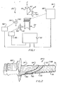
- FIG. 1 An apparatus 20 for use in applying a covering having a uniform or non-uniform thickness to a workpiece 22 is illustrated-in Figures 1 and 3.
- the apparatus 20 includes a spray gun 24 which is used to apply the covering to the workpiece 22.
- a sensor assembly 28 is utilized to determine the thickness of the covering applied to the workpiece 22 by the spray gun 24.
- a control apparatus 32 is utilized to control the operation of the spray gun 24 to apply a covering of a desired thickness to the workpiece 22.
- the control apparatus 32 co-operates with the sensor assembly 28 and spray gun 24 to effect an extremely accurate application of material on the workpiece 22.
- the accuracy with which the material has to be applied to the workpiece will vary with variations in the workpiece and the environment in which it is to be used, in one specific instance the thickness of the covering varied by less than plus or minus 1.5 mils (0.0015 inch) from a desired thickness.
- the sensor assembly 28 is capable of repeatedly detecting the thickness of the covering with an error of less than 0.5 mils (0.0005 inch).
- a drive apparatus 36 is utilized to effect relative movement between the workpiece 22 and the spray gun 24 along each of three .orthogonal axes which have been indicated as the X, Y and Z axes in Figure 1.
- the drive apparatus 36 is effective to rotate the workpiece about each of the three axes in the manner indicated schematically by the arcuate arrows 40, 42, and 44 in Figure 1.
- a workpiece 22 having a complex configuration can be accurately sprayed with a covering of material by the gun 24.
- the drive apparatus 36 is effective to move the workpiece along the X and Y axes and to move the spray gun 24 along the Z axis.
- the drive apparatus 36 includes a workpiece drive assembly 48 ( Figure 1) which is operable by the control apparatus 32 to move the workpiece 22 relative to the spray gun 24 along the X and/or Y axes and to rotate the workpiece around the X, Y, and/or Z axes.
- a spray gun drive assembly 50 is provided to move the spray gun 24 along the Z axis. It should be noted that the Z axis has been considered as extending through the centre of the workpiece and that the spray gun 24 is displaced to one side of the Z axis. Although.the spray gun 24 is displaced at one side of the Z axis, it is moved along the Z axis by the drive apparatus 50 in the manner illustrated schematically by the arrow 54 in Figure 1.
- the spray gun 24 could be rotated relative to the workpiece 22 in such a manner as to effect one or more of the rotational components of relative movement between the spray gun 24 and workpiece 22.
- the spray gun 24 could be moved along the X and Y axes if desired.
- a sensor drive assembly 58 is provided to effect relative movement between the sensor assembly 28 and the workpiece 22.
- the sensor assembly 28 is moved along only the Z axis by the drive assembly 58 in the manner indicated schematically by the arrow 60 in Figure 1.
- the workpiece drive assembly 48 is ; operable to effect movement of the workpiece 22 relative to the sensor assembly 28 along the X and Y axes and to rotate the workpiece 22 about the X, Y, and Z axes.
- six degrees of freedom of relative movement are available between the workpiece 22 and the spray gun 24 and between the workpiece and the sensor assembly 28.
- the workpiece 22 could have many different constructions and could be formed of many different materials.
- the primary requisite for the workpiece 22 is only that it be able to receive and support a covering applied to it by the spray gun-24.
- the workpiece 22 is an airfoil (see Figure 2) which is utilized in a turbine engine.
- the spray gun 24 is of the electric arc plasma spray type which is capable of directing heat-softened particles entrained in a high velocity plasma stream toward the airfoil 22.
- the plasma spray gun 24 ( Figure 3) is of the multiport type which is supplied with powdered material of two different compositions.
- the plasma spray gun 24 is a 40kw unit made by Plasmadyne, Inc., a division of Geotel, Inc. of Amityville, New York, U.S.A. and is of the same general type as the plasma spray guns illustrated in'U.S. Patent Nos. 3,914,573 and 2,961,335.
- a covering 64 ( Figure 2) is applied to a blade portion 68 of the airfoil 22.
- the covering extends over the major side surfaces 66, longitudinally extending leading and trailing edges 70 and 72, the top surface of a platform at a root end portion 74, and a tip end portion 76 of the airfoil 22. If the trailing edge of the blade 68 is provided with'cooling passages, the trailing edge is not covered to prevent blockage of the passages.
- the general construction of the airfoil 22 is well known and will not be further described herein in order to provide prolixity of description.
- the covering 64 which is applied to the airfoil 22 by the spray gun 24 includes a bond coat or covering 80 which is applied directly against the surface of the airfoil 22.
- the bond covering 80 is also effective to prevent oxidation of the airfoil 22.
- a thermal barrier coating or covering 82 is applied over the bond covering 80. It is contemplated that a transition covering formed by a mixture of the materials used in the thermal barrier and bond coverings could be utilized between the two coverings to provide a strong interconnection capable of withstanding severe operating conditions.
- the bond covering 80 was a NiCrAlY covering which was 4 mils (0.004 inch) thick.
- the bond covering 80 was applied by moving the _gun 24 at a uniform surface scan speed of approximately 16 inches per second.
- the bond-covering 80 was applied in a plurality of passes of the spray gun 24 with a covering of approximately 2 mils (0.002 inch) thickness being applied on a first pass of the gun 24 and 1 mil (0.001 inch) being applied on each subsequent pass of the spray gun 24.
- the thermal barrier covering 82 was formed of yttria stabilized zirconium oxide.
- the thermal barrier covering can be approximately 12 to 30 mils thick depending upon the requirements for the particular airfoil.
- the thermal barrier zirconium oxide covering 82 was- applied in a number of passes of the gun 24. A covering of approximately 0.8 mils thickness was applied on each successive pass of the gun. However, it should be understood that the thickness of the covering applied on each pass of the gun 24 can be varied by varying the speed of movement of the gun relative to the airfoil or by varying the feed rate of material to the gun.
- a transition covering is advantageously applied to the bond covering before the thermal barrier covering is applied.
- This transition covering is formed of a mixture of the materials in the bond and thermal barrier coverings..
- the transition covering promotes a strong connection between the bond and thermal barrier coverings even though they have different coefficients of thermal expansion.
- the transition covering is formed by a mixture of yttria stabilized zirconia and NiCrAlY alloy.
- the bond and thermal barrier coverings 80 and 82 each have a thickness which varies by less than 1.5 mils (0.0015 inch) from a desired thickness throughout the area of the coatingroverlying the blade 68. If a transition covering is utilized, it is applied with a similar degree of accuracy.
- the apparatus 20 will be utilized to apply coverings to many different articles, the method of applying the covering 64 to the airfoil 22 will be described to illustrate one specific method of operating the apparatus 20.
- the apparatus 20 could be constructed differently and operated in a different manner if the characteristics of the article being covered so require or allow.
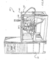
- the airfoil When the multilayer covering 64 is to be applied to the airfoil 22 by the apparatus 20, the airfoil is mounted in a gripper assembly 86 (see Figures 3 and 4).
- the gripper assembly 86 engages the root or platform end 88 (see Figure 2) of the airfoil 22 and is provided with a shield or barrier plate 92 ( Figure 4).
- the barrier plate 92 prevents excess spray from the gun 24 impinging directly against the clamp which holds the root end portion 88 of the airfoil.
- the barrier plate 92 also shields the root and edges of the platform. This tends to minimize thermal effects on the clamp and resulting inaccuracies in the positioning of the airfoil 22.
- a stream of a cooling fluid in the present instance carbon dioxide gas, is directed against the airfoil 22 to cool the airfoil and further reduce thermal effects.
- the-apparatus 20 operates satisfactorily to apply coverings to airfoils without utilizing additional coolant flow through internal _passages in the ajrfoiL: However, when the airfoil is constructed with internal passages, providing a flow of cooling fluid through these passages does serve to further alleviate thermal effects.
- the exact locations of a plurality of points on the outer surface of the airfoil 22 are determined by using the sensor assembly 28.
- the exact locations of the various points on the surface of the airfoil 22 are transmitted to the control assembly 32 ( Figures 1 and 3) where they are stored for future reference. It should be noted that since the sensor assembly 28 is immediately adjacent to the spray gun 24, the position of various portions of the surface of the airfoil 22 can be accurately determined by the sensor assembly 28 while the airfoil 22 is held by the same gripper assembly 86 ( Figure 4) as is used to hold the airfoil during the application of the covering 64 to the airfoil by the spray gun 24.
- the control apparatus 32 ( Figure 1) effects movement of the workpiece drive assembly 48 to accurately position the airfoil 22 in front of the spray gun 24.
- the spray gun 24 is then activated.
- Powdered material for the bond covering 80 ( Figure 2) is entrained in a suitable gas and conducted in a known manner to the spray gun through a hose or conduit 96 (see Figure 4).
- electrical energy and cooling liquids are conducted to and from the spray gun 24 through hoses or conduits 98 and 100.
- inert gas such as argon is connected to the spray gun 24 through the hose or conduit 102.
- the spray gun 24 is activated and an electric arc is produced.
- Gas fed under pressure through the conduit 102 is conducted through the arc.
- the gas is ionized and heated in the electric arc.
- the heated ionized gas is a body of plasma which flows toward a spray gun exit port 1 06.
- Powdered material from the conduit 96 is directed into the high-temperature accelerating stream of plasma where it is heated.
- the heated powder particles are entrained in the plasma stream and are directed by the spray gun 24 against the airfoil 22.
- the powdered material conducted through the conduit 96 and directed toward the workpiece is an NiCrAlY alloy.
- a spray gun drive motor 110 ( Figure 4) is operated to drive a vertical screw 112 which extends parallel to the Z axis. This moves the spray gun upward at a uniform speed so that the plasma stream is effective to apply a generally vertically extending strip of material to the airfoil 22.
- the thickness of the covering applied over a surface area of the blade can be controlled by controlling the speed of movement of the gun.
- the control assembly 32 effects operation of the drive motor 110 to move the spray gun at a relatively slow speed.
- the control assembly 32 causes the motor 110 to operate at a higher speed.
- the spray gun 24 When the spray gun 24 reaches the end of a vertical upward stroke, it directs the plasma stream above the airfoil 22.
- the control apparatus 32 is then effective to activate the workpiece drive assembly 48 to index the airfoil 22. This causes a next adjacent portion of the airfoil 22 to be aligned to receive material from the spray gun 24.
- the spray gun 24 is then moved downwardly to apply a next succeeding strip of material to the airfoil 22 adjacent to and overlapping the preceding strip.
- the strips were approximately 12 mm wide and had central axes which were spaced 5 mm apart.
- the spray gun 24 When the spray gun 24 reaches the end of a vertical downward stroke, it directs the plasma stream beneath the airfoil 22. The airfoil 22 is then indexed again to position it to receive the next succeeding strip. This next strip is adjacent to and overlaps the last strip. The next strip is applied to the airfoil 22 as the spray gun 24 is moved upwardly along the Z axis by operation of the motor 110 under the influence of the control apparatus 32.
- the strips of material are applied in succession around the airfoil 22 by moving the spray gun 24 along the Z axis and by accurately positioning the airfoil relative to the spray gun before each stroke is undertaken.
- the airfoil 22 has an extremely complex configuration, successive surface areas on the airfoil can be accurately positioned relative to the spray gun 24 by the drive assembly 48. This is because the drive assembly 48 can move the airfoil along the X and Y axes and can rotate the airfoil about the X, Y, and Z axes.
- the exact positions to which the airfoil is indexed on each of the work strokes of the spray gun 24 is determined by a program in the control assembly 32.
- the spray gun 24 is operated to apply a next succeeding layer over the first layer.
- the longitudinally extending strips of the next succeeding layer have central axes which may be offset from the central axes of the strips of the first layer. This is done because there tends to be a slightly greater accumulation of material at the centre of the strip than at the edges of the strip.
- variations in the thickness of the bond coating 80 are.minimized.
- control apparatus 32 can effect operation of the drive assembly 48 to cause a slight dithering or sidewise movement of the blade along the X axis during a vertical stroke of the spray gun 24 along the Z axis to thereby promote blending of the strips applied to the airfoil 22 during work strokes of the spray gun 24.
- the accuracy with which the covering is applied to the airfoil is promoted by applying the covering in successive layers with the longitudinal axes of the strips in each layer offset relative to the longitudinal axes of the strips of the next adjacent layer. -However, sufficient uniformity of covering thickness (plus or minus 1.5 mils) may be obtained without offsetting the longitudinal central axes of the strips.
- the total thickness of a covering can be applied by spraying a plurality of strips on top of each other and then indexing the blade and spraying a plurality of strips adjacent to the first group of strips. It is contemplated that the specific manner in which the strips are applied will be varied to suit the configuration of a particular workpiece to which they are being applied and the accuracy with which the covering must be applied to the workpiece.
- the thickness of the bond covering 80 is measured.
- the airfoil 22 is moved along the X axis from a spray receiving position adjacent to the spray gun 24 to a position adjacent to the sensor assembly 28.
- the sensor assembly 28 is then operated to detect the thickness of the bond covering 80 which has been applied to the airfoil.
- the bond covering 80 may have a thickness which is less than the desired thickness at each of the locations where the sensor assembly 28 initially sensed the position of the airfoil surface.
- the control assembly 32 determines the difference between the desired thickness and the actual thickness of the bond covering 80 applied to the airfoil 22 by the operation of the spray gun 24. This thickness determination is made while the airfoil remains in the gripper assembly 86. If the airfoil 22 was removed from the gripper assembly 86, errors would, in all probability, be introduced when the airfoil was repositioned in the gripper assembly.
- the airfoil 22 is moved back into alignment with the spray gun 24.
- the spray gun 24 is then operated in the manner previously explained to increase the thickness of the bond covering as and where required.
- the sensor assembly 28 is again utilized to detect whether or not the actual thickness of the bond covering 80 is the desired thickness. If the control apparatus 32 determines that additional material should be applied to the covering 80 in order that it will have the requisite thickness, the airfoil 22 is again moved into alignment with the spray gun 24 and additional material is applied to the airfoil.
- the covering 80 has a thickness which differs from the desired thickness by less than plus or minus 1.5 mil (0.0015 inch). It should be noted that, due to the thinness of the bond coat, it is often possible to achieve the required thickness of plus or minus 1.5 mils in the first spray sequence.
- a thermal barrier covering 82 is applied directly over the bond covering without removing the airfoil 22 from the gripper assembly 86.
- the thermal barrier covering 82 is formed of yttria stabilized zirconia.
- the thermal barrier covering has a thickness of between 12 and 30 mils depending upon the environment in which the airfoil 22 is to be utilized.
- the spray gun 24 is used to apply the thermal barrier covering 82 to the airfoil 22 in the same manner in which the spray gun was used to apply the bond covering 80 to the airfoil. However, during the application of the thermal barrier covering 82, powdered yttria stabilized ,zirconia is conducted to the multiport spray gun 24 through the conduit 120 (see Figure 4).
- the spray gun 24 is then effective to direct a plasma spray of yttria-stabilized zirconia toward the airfoil 22 in the manner previously explained in connection with the bond covering 80.
- the spray gun drive motor 110 is operated to cause the drive screw 112 to move the spray gun 24 along a vertical path.
- movement of the spray gun 24 along a path extending parallel to the Z axis is guided by a pair of upstanding rods 124 and 126 ( Figure 4).
- strips of yttria stabilized zirconia are sequentially applied to the airfoil 22. These strips extend from the root end portion 74 of the airfoil to the tip end portion 76 of the airfoil.
- a thermal barrier covering 82 of a desired thickness a plurality of layers of strips of material are sequenti- ally applied to the airfoil 22. Any tendency to form longitudinally extending relatively thick areas in the thermal barrier covering 82 is minimized by offsetting the longitudinal axes of strips in adjacent layers of the thermal barrier covering or by judicious selection of strip overlaps.
- the workpiece drive assembly 48 (see Figure 1) is operated to move the airfoil 22 (see Figure 4) to a position adjacent to the sensor assembly 28.
- the sensor assembly 28 is utilizeG in conjunction with the control apparatus 32 ( Figure 1) to detect the actual thickness of the thermal barrier covering 82.
- the airfoil 22 remains in the gripper assembly 66 from the time that the location of various points on the airfoil are sensed by the sensor assembly 28 prior to initiation of the application of the bond covering 80 until the thermal barrier covering 82 is completed. This eliminates any possibility of errors which could result from connecting and disconnect ing the airfoil 22 from the gripper assembly 86.
- the spray gun 24 is again operated to increase the thickness of the thermal barrier coating 82.
- the sensor assembly 28 is operated to sense the thickness of the thermal barrier coating at a plurality of locations on the airfoil 22. If for some unforeseen reason the thermal barrier covering 82 should have different thicknesses at different locations on the airfoil 22, the control apparatus 32 is effective to cause the spray gun 24 to operate in sucn a manner as to eliminate the variations in the thickness of the thermal barrier covering 82.
- the control apparatus 32 would effect operation of the spray gun to make a plurality of passes or scans along the airfoil in the area where the thermal barrier coating 82 is relatively thin and would make a fewer number of passes or scans along the portion of the airfoil 22 where.the thermal barrier coating was relatively thick.
- the thickness of the covering applied in a portion of a strip can be varied by varying the speed of movement of the spray gun 24 as a strip is applied.
- the thermal barrier covering 82 By repetitively sensing the thickness of the thermal barrier covering 82 and controlling the operation of the spray gun 24 with the control apparatus 32 as a function of the sensed thickness of the thermal barrier covering at a plurality of locations on the airfoil 22, the thermal barrier covering 82 will have a thickness which varies by less than 3 mils (0.003 inch).
- the thermal barrier covering 82 is applied directly over the bond covering 80 on the airfoil 22, it is contemplated that a transition covering may be utilized between the bond and thermal barrier coverings.
- the control assembly 32 is effective to cause the spray gun 24 to apply a mixture of the bond covering materials and the thermal barrier covering materials over the bond covering 80 before the thermal barrier covering 82 is applied.
- the thickness of the transition covering is measured with the sensor assembly 28 in the manner previously explained in connection with the bond and thermal' barrier coverings..
- the thermal barrier covering is applied over the transition covering. It should be noted that the airfoil 22 is continuously maintained in the gripper assembly 86 during application of the bond covering, measuring of the thickness of the bond covering, application of the transition covering, measuring of the thickness of the transition covering, application of the thermal barrier covering and measuring of the thickness of the thermal barrier covering.
- the operation of the spray gun 24 has been described herein in connection with the application of a bond covering 80 and a thermal barrier covering 82 to an airfoil 22, it is contemplated that the method and apparatus of the present invention will be utilized to apply coverings over portions of many different types of workpieces, It is contemplated that the coverings applied to these workpieces will be formed of many different types of materials and that there may or may not be a plurality of coverings applied to the same workpiece by the spray gun. In addition, it is contemplated that spray guns other than the particular plasma spray gun disclosed herein will be utilized to apply different types of materials to the workpieces.
- the workpiece drive assembly 48 is illustrated schematically in Figure 5. A specific embodiment of the workpiece drive assembly 48 is shown in Figure 6.
- the workpiece drive assembly 48 includes a carriage 130 which is supported for movement along both the X and Y axes ( Figure 5). Although they could have different orientations, the Y axis extends generally parallel to the path of flow of material from the spray gun 24. The X axis extends generally perpendicular to the path of flow of material from the spray gun 24.
- the carriage 130 is supported for movement along the X axis by a pair of parallel guide bars 134 and 136 (see Figure 5).
- the guide bars 134 and 13 6 are fixedly connected to a pair of parallel longitud. inally extending upper frame members 138 and 140 ( Figure 3) of a framework 142.
- the carriage 130 is supported for movement along the Y axis by a pair of parallel support rods 146 and 148 (see Figure 6).
- the support rods 146 and 148 are connected with the guide bars 134 and 136 by four bearing blocks, only two of which are shown at 150 and 152 in Figure 5.
- the carriage 130 is connected with the support bars 146 and 148 by suitable bearings 154 and 156 and 158 ( Figure 6).
- the carriage 130 is supported for movement along the X axis by the parallel guide bars 134 and 136.
- the carriage 130 is supported for movement along the Y axis by the parallel guide bars 146 and 148.
- the guide bars 146 and 148 move along the X axis with the carriage 130.
- a drive screw 162 is rotated by a reversible electric motor 164. It should be noted that the drive screw 162 extends parallel to the X axis and the guide bars 134 and 136.
- the drive screw 162 is connected with the bearing block 150 by a suitable ball nut or internally threaded drive element.
- the carriage 130 is moved along the Y axis and the parallel guide bars 146 and 148 by a drive screw 166.
- the drive screw 166 is rotated by a reversible drive motor 168 ( Figure 5).
- the airfoil engaging gripper assembly 86 is connected with a lower end port-ion of a longitudinally extending support member 172 ( Figure 5).
- the support member is pivotally connected with the carriage 130 at a universal joint 176.
- the universal joint 176 connects the support member 172 with the carriage 130 so as to allow the gripper assembly 86 freedom of sidewise movement in every direction within certain defined limits.
- the universal joint 176 allows the support member 172 to rotate about its own longitudinally extending central axis to provide for rotational movement of the gripper assembly 86 and workpiece about the Z axis.
- the pivot joint 176 also enables the support member 172 to be pivoted about a point which is coincident with the centre of the universal joint in the manner that the support member 172 moves in a conically shaped envelope and the gripper assembly 86 moves through a circle relative to the carriage 130. This enables the airfoil 22 to be pivoted about both the X axis and the Y axis.
- a slide member 180 (see Figures 5 and 6) is movable under the influence of a reversible drive motor 182 ( Figure 6) and a drive screw 184.
- the drive screw 184 effects movement of the slide member 180 along a path which extends parallel to the Y axis. This movement of the slide member 180 is effective to pivot the support member 172 about the, X axis at the universal joint 176.
- the support member 172 is pivoted about the Y axis by movement of a second slide member 188 under the influence of a reversible electric drive motor 190 (see Figure 6) and a drive screw 192.
- a reversible electric drive motor 190 see Figure 6
- the drive screw 192 moves the slide 188 along a path which extends parallel to the X axis and perpendicular to the Y axis. This effects pivotal movement of the support member 172 about the Y axis at the universal joint 176.
- a drive motor 196 is operable through a speed reduction assembly 198 to rotate the support member 172 about its central axis. It should be understood that although operation of the motor 182 effects pivotal movement of the workpiece about the X axis and that operation of the motor 190 effects pivotal movement of the workpiece about the Y axis, both motors could be simultaneously operated to effect simultaneous pivotal movement of the airfoil 22 about the pivot joint 176 to any desired position relative to the spray gun 24 and sensor assembly 28.
- the motor 196 could be energized to rotate the airfoil 22 about the Z axis. It is also contemplated that simultaneously with pivotal movement of the airfoil 22 about the X, Y, and Z axes, the drive motors 164 and 168 could be energized to move the airfoil 22 along the X and Y axes.
- the workpiece drive assembly 48 provides for five degrees of freedom of relative movement of the workpiece 22 relative to the spray gun 24 and sensor assembly 28.
- the workpiece 22 can be moved along the X and Y axes and can be pivoted about the X, Y, and Z axes by the drive assembly 48.
- the sixth degree of freedom of relative movement between the workpiece and the spray gun 24 and sensor assembly 28 is achieved by the spray gun drive assembly 50 and the sensor drive assembly 58.
- the spray gun drive assembly 50 includes the motor 110 ( Figure 4) which rotates the drive screw 112 through a pair of gears 199 and 200. Upon operation of the reversible electric drive motor 110, the spray gun 24 is moved along the vertical guide bars 124 and 126 which extend parallel to the Z axis.
- the sensor assembly 28 is moved by the drive assembly 58 in much the same manner as in which the spray gun 24 is moved by the drive assembly 50.
- the drive assembly 58 includes a reversible electric motor 205 ( Figure 4) which is connected by a pair of gears 206 and 207 with a vertical drive screw 208.
- the drive screw 20B extends parallel to the Z axis and to a pair of upright guide members 209 and 211.
- the sensor assembly 28 is utilized in determining the thickness of the covering applied to a workpiece, such as the airfoil 22.
- the sensor assembly 28 utilizes electrical energy to detect the thickness of a covering without engaging the covering with a solid object.
- the sensor assembly 28 includes an electric light 210 which is a noncoherent light source ( Figure 8).
- Light from the lamp 210 is directed into a fibre optic bundle 214.
- the light from the fibre optic bundle 214 is transmitted through a lens assembly or optical extender 216 against a surface 218 of the airfoil 22. At least a portion of the light is reflected back from the surface 218 of the airfoil 22 to a fibre optic bundle 224 which leads to a photosensor 226.
- the two fibre optic bundles 214 and 224 are randomly mixed in a main fibre optic bundle 228. Therefore, a portion of the light which is reflected from the surface 218 is directed back to the light source 210 through the fibre optic bundle 214 while the remainder of the light is directed to the photosensor 226 through the fibre optic bundle 224.
- the lens assembly 216 includes a collimating lens 232 and a condensing lens 234.
- the condensing lens 234 is effective to direct the light from the light source toward a focal point which has been indicated at 236 in Figure 8.
- the construction of the sensor assembly 28 is the same as is disclosed in U.S. Patent No. 3,940,608 and is commercially available from MTI Instruments, Latham, New York as a model KD-100 Fotonic Sensor and has a 2.2 millimetre diameter probe.
- the sensor assembly 28 provides a clear indication of when a surface area on an object is spaced apart from the condensing lens 234 by a distance which is equal to the focal length of the lens.
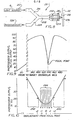
- the surface area of the airfoil 22 is at the focal point, as shown in Figure 8, the amount of light which is reflected back to the light source 210 is maximized and the amount of light which is reflected to the sensor tends to be minimized. This is because the light rays reflected from the surface of the workpiece 22 through the condensing lens 234 and collimating lens 232 are directed back to the same fibre optic conduits from which they originated, that is back to the fibre optic conduits in the bundle 228 leading to the bundle 214. The manner in which this occurs has been shown graphically in Figure 9.
- the light reflected back to the photosensor begins to decrease when the lens 234 is spaced approximately 420 mils from the surface 218 of the airfoil 22. This sharp decrease continues until the focal point distance is reached at approximately 433 mils. As the distance increases from the focal point distance, the amount of light reflected from the photosensor 226 sharply increases again until the lens 234 is located about 460 mils from the surface of the workpiece. The light reflected back to the photosensor then decreases in a reasonably linear manner as the distance increases.
- the relationship between the amount of light reflected to the light source 210 from the surface 218 varies in a manner which is substantially inverse to the manner in which the light reflected to the photosensor 226 varies with movement of the sensor assembly 28.
- the sensor assembly 28 is spaced from the surface 218 by a distance equal to the focal distance of the lens 234, the amount of light reflected to the photosensor 226 tends to be minimized. At this time, the amount of light reflected to the light source 210 is maximized.
- the amount of light reflected to the light source 210 decreases as the amount of light reflected to the photosensor 226 increases in the manner shown in Figure-9.
- the uncoated airfoil is moved by the workpiece drive assembly 48 relative to the sensor assembly 28 until the surface of the airfoil is at the focal point, that is until the surface of the workpiece is spaced apart from the lens 234 by the focal distance of 433 mils.
- the position of the airfoil 22 at this time is stored in the control apparatus 32. This original positioning of the airfoil 22 provides a reference position from which subsequent measurements are determined.
- the workpiece drive assembly 48 is operated under the influence of the control assembly 32 to position the outer surface area of the initial port- ion of the covering at the focal point of the lens 234.
- the surface area of the covering is at the focal point of the lens 234, that is when the surface area of the covering is 433 mils from the lens 234, the position of the airfoil 22 will be offset from its original or reference position by a distance equal to the thickness of the covering.
- the control apparatus 32 can determine the actual thickness of the initial portion of the covering applied to the airfoil 22 by subtracting the position of the airfoil when the outer surface area of the covering is at the focal point of the lens 234 from the previously stored reference position. The thickness of the initial portion of the covering is then compared with the desired thickness of the covering to determine the amount by which the thickness of the initial portion of the covering would be increased in order to have a covering of the desired thickness. The control apparatus 32 then effects operation of the spray gun 24 to increase the thickness of the covering until it has the desired thickness. In this manner, the thickness of the bond coat covering 80 can be controlled to within plus or minus 1.5 mils (0.0015 inch) of a desired thickness.
- the thermal barrier coat covering 82 is applied over the bond coat covering.
- the initial reference position of the airfoil is utilized.
- the combined thickness of the bond coat covering.80 and the portion of the thermal barrier coat covering 82 which has been applied to the airfoil 22 is measured. This combined thickness is compared with a desired combined thickness for both coverings to determine the amount by which the thickness of the thermal barrier covering 82 must be increased.
- the thickness of the thermal barrier covering can also be controlled to within plus or minus 1.5 mils (0.0015 inch).
- FIG. 10 The manner in which the focal point for the lens 234 is detected has been illustrated graphically in Figure 10.
- a set of ten memory locations is set up in the control apparatus 32 to constitute a first-in-first-out (FIFO) memory.
- FIFO first-in-first-out
- the voltage is read and entered into the first memory location in the first-in-first-out memory.
- a new voltage reading is entered into the first memory location and all previous measurements are moved back by one memory location. A reading which has reached the last memory location is lost on the next step. Therefore, the memory always contains the last ten voltage.readings and their corresponding probe coordinate steps.
- the value representing the focal point is assumed to have been detected and the coordinate of the sixth memory location is taken as the valley position.
- the program in the control apparatus 32 is set up to detect the negative slope preceding the valley and the positive slope following the valley by looking for appropriate differences between the first and last reading to the FIFO memory. Parameters that can be varied automatically if searching for the valley are the voltage differences to define the slopes and the valley and the position in which the valley detect routine starts.
- the manner in which the readings in the FIFO memory relate to a curve of photosensor output voltage has been illustrated schematically in Figure 10.
- the initial data entered into the FIFO memory could be considered as being relative to the photosensor output voltage curve in the manner illustrated schematically at 242 in Figure 10. It should be noted that at the position indicated at 242 in Figure 10 the tenth reading, that is the reading being taken, is substantially less than the zero reading, that is the reading stored in the tenth memory location of the FIFO memory. After the sensor assembly 28 has been moved away from the workpiece through the focal point, the readings stored in the FIFO memory locations could be considered as being relative to the photosensor output voltage curve in the manner- illustrated schematically at 240 in Figure 10.
- the tenth reading that is the reading being taken
- the zero reading that is the reading stored in the tenth memory location of the FIFO memory. Therefore, it can be readily determined that in moving the sensor assembly 28 from the position indicated at 242 in Figure 10 to the position indicated at 240 in Figure 10 the bottom of the valley or focal point position was passed.
- the tenth reading that is the reading being taken, will be less than the first or zero reading until the position indicated schematically at 244 is reached.
- the sensor assembly moves through the position in which the focal point of the lens 234 is on the strface of the workpiece. It should be noted that after the sensor assembly 28 moves through the focal point position, the successive voltage readings, that is the tenth reading being taken, will stop decreasing and start increasing.
- the voltage reading being taken When the sensor assembly 28 has moved through the focal point position to the position indicated schematically at 244 in Figure 10, the voltage reading being taken, that is the tenth reading, will be approximately equal to but slightly less than the voltage reading stored in the tenth memory location. On the next successive .incremental step of relative movement between the sensor assembly and the workpiece, the voltage reading being taken, that is the tenth reading, will exceed the voltage reading stored in the tenth memory location. This indicates that the bottom of the valley or focal point is disposed at a location between the location where the tenth voltage reading is being taken and the location where the zero voltage reading was previously taken.
- the reading stored in the sixth FIFO memory location is assumed to have been made at the focal point position.
- the readings in each of the FIFO memory locations could be compared in order to determine which reading was the lowest to more accurately determine the focal point position.
- the relative movement between the sensor assembly 28 and the workpiece 22 is obtained by moving the workpiece relative to the sensor assembly with the drive apparatus 36.
- the sensor assembly could be moved relative to the workpiece in the manner assumed above in connection with Figure 10.
- the sensor assembly 28 has been described herein in connection with a method of applying a covering to a workpiece, it is contemplated that the sensor assembly could be used in association with a FIFO memory to locate any surface.
- the sensor assembly could be utilized in association with an operation in which material is removed from a workpiece.
- the number of measurements taken in each step can be one or any multiple of two up to one hundred and twenty-eight.
- the value entered into the FIFO memory is then the average of the readings minimizing random noise effects.
- the number of memory locations in the FIFO can be varied up to any desired number. This process of detecting the focal point of the lens 234 shows a measurement repeatability with an error of less than plus or minus 0.5 mils (0.0005 inch).
- the airfoil or workpiece 22 has been moved-relative to the sensor assembly 28 to detect when a surface on the workpiece is spaced a predetermined distance, that is the focal distance, from the sensor assembly. It is contemplated that the sensor assembly could be moved relative to the workpiece or airfoil 22 if desired. Although for safety reasons it is preferred to approach the focal distance from a point whici, is closer to the workpiece than the focal distance, that is by increasing the distance between the sensor assembly 28 and the workpiece or airfoil 22, it is contemplated that the focal point could be detected by decreasing the distance between the workpiece or airfoil 22 and the sensor assembly 28.
- a sensor assembly using a coherent light source (laser gauge), or a capacitive sensor could be utilized if desired. It is believed that the accuracy with which measurements are made will be promoted with any known type of sensor by maintaining the workpiece or airfoil 22 in the clamp assembly 86 during both the application of a covering to the airfoil and measurement of the covering.
- control apparatus includes a microprocessor 250 (see Figure 11) having peripheral interface adaptors 252, 254, 256, and 258 connected with the various drive motors, the optical sensor assembly, display outputs and manual control inputs, and the spray gun 24.
- control circuitry connected with the X axis drive motor 164 has been shown in Figure 11, it should be understood that similar control circuitry is connected with the spray gun and sensor drive motors 110 and 205 and with the other drive motors in the workpiece drive assembly 48, that is with the drive motors 168, 182, 190, and 196.
- the microprocessor 250 could have many different constructions, in one specific instance the microprocessor 250 was a type M 6800 microprocessor from Motorola Communications & Electronics, Inc. of Phoenix, Arizona.
- zero reference stops are utilized with all of the various drive motors, including the X axis drive motor 164. Provision of zero reference stops allowed position encoders to be eliminated. Accordingly, a reference register was provided for each motor in association with a digital comparator and an up/down counter.
- the optical sensor 28 was connected with an analog-to-digital convertor which was sampled by the microprocessor control system.
- the memory locations which constituted the first-in-first-out memory unit were also provided in the microprocessor.
- a printer 262 (see Figure 11) is provided in the control apparatus 32 to provide a printed record of the thickness of the covering applied to the airfoil.
- the sensor assembly 28 is utilized to detect the thickness of the covering applied to the airfoil 22 at a plurality of points on the airfoil.
- the printer 262 is utilized to record the thickness of the bond coat covering 80 and the thermal barrier coat covering 82 at each of a plurality of points on the airfoil 22. If a transition covering is utilized between the bond and thermal barrier coverings, the printer 262 would also record the thickness of the transition covering at each of a plurality of points on the airfoil.
- control assembly 32 is effective to compensate for any variations which may occur during the application of the various coverings to the airfoil 22. This is because the sensor assembly 28 is utilized during the operation of the apparatus 20 to detect any deviations which may occur in the thickness of the covering.
- the control assembly 32 is effective to regulate operation of the spray gun 24 to compensate for any deviation in the thickness of the covering. During normal operation of the apparatus 20 this results in zero defects.
- the apparatus 20 has been described in connection with the application of bond covering 80 and a thermal barrier covering 82 of uniform thicknesses to an airfoil. However, it is contemplated that the apparatus 20 will be utilized to apply non-uniform coverings with the resulting construction of a three dimensional object having a configuration which has very little resemblance to the configuration of the workpiece upon which the non-uniform covering is deposited.
- Figures 12 to 16 an example of an application of such a non-uniform covering to fabricate an airfoil is disclosed.
- a non-uniform covering could be applied to any base capable of receiving the covering in order to provide for the build-up of material in such a manner as to form an object having any desired configuration.
- a core 270 is provided. Although the core 270 does have a configuration which slightly resembles the configuration of an airfoil, it is contemplated that the core 270 could have any desired configuration. In the present instance the configuration of the core 270 was selected in order to provide internal passages of a desired configuration within the airfoil.
- the core 270 is covered with a plurality of non-uniform layers, which have been indicated at 274 in Figure 13, to form the basic configuration of an airfoil. It should be noted that the layers 274 were applied with the spray gun 24 by making more scans or passes across areas where the material is relatively thick than across areas where the material is relatively thin. Reference locations corresponding to the location of many different points on the surface of the core 270 were stored in the microprocessor before the non-uniform covering 274 was applied.
- thermal barrier covering 278 is applied over the non-uniform covering 274.
- the thermal barrier covering 278 is of a material which is different than the material of the covering 274 and may be provided with a bond coat or covering, similar to the bond covering 80 of Figure 2.
- the core or base 270 is removed to provide an internal passage 282 in the airfoil 284 (see Figure 15).
- the hollow airfoil 284 is then subjected to hot isostatic pressing to increase the density of the airfoil 284 and to eliminate any porosity which may be present in the non-uniform coating 274.
- the core 270 can be made of any material which does not adversely react with the non-uniform covering 274 and which is easily removed as by being melted out or leached. With one particular type of airfoil, the core 270 could advantageously be made of aluminium.
- the present invention provides a new and improved method and apparatus for applying a covering of either uniform or non-uniform thickness to a workpiece.
- a non-uniform covering is applied to a workpiece
- the resultant product will have a configuration which is different than the configuration of the workpiece to which the covering was applied.
- the workpiece to which the covering is applied can have many different constructions and may be formed of many different materials so long as the workpiece is capable of receiving the covering.
- a covering 64 of a uniform thickness is accurately applied to an airfoil 22.
- an airfoil 284 is formed on a workpiece or core 270 which is subsequently removed from the airfoil. It should be understood that it is contemplated that the present invention could be utilized in association with many different types of objects other than airfoils.
- An apparatus constructed in accordance with the present invention includes a spray gun 24 which is utilized to direct a flow of material toward a workpiece, such as the airfoil 22.
- a sensor assembly 28 is provided to determine the thickness of the covering 64 applied to the workpiece 22 without engaging the workpiece.
- a control assembly 32 is connected with the sensor assembly 28 and the spray gun 24.- The control assembly 32 is effective to compare the thickness of the covering of material which is actually applied to the workpiece 22 with a desired thickness and is effective to regulate the operation of the spray gun 24 in such a manner as to effect the application to the workpiece of a covering having the desired thickness.
- the optical sensor assembly 28 is utilized to detect when a surface area on either the workpiece or a covering is at the focal point of a lens 234. This is accomplished by sensing changes in the light reflected from the surface area with changes in the distance between the sensor assembly 28 and the workpiece.
- the plasma spray gun 24 By utilizing the method and apparatus of the present invention, it is possible to control the operation of the plasma spray gun 24 to apply a covering 64 which will have a thickness which is within 1.5 mils (0.0015 inch) of a desired thickness.
- the accurate application of the covering 64 to the workpiece 22 is promoted by detecting the thickness of the covering at several different points on the workpiece and controlling the operation of the plasma spray gun 24 as a function of differences between the desired covering thickness::and the actual covering thickness as sensed at several points on the workpiece.
- the application of a covering 64 of the desired thickness to the workpiece 22 is further promoted by applying the covering in layers formed of longitudinally extending strips.
- the central axes of the strips in one layer may be offset from the central axes of the strip of a next adjacent layer for more precise control of overall thickness uniformity.
- an apparatus constructed in accordance with the present invention can effect relative movement between the airfoil and a spray gun along three different axes.
- the apparatus can effect rotational movement between the airfoil and the spray gun about three axes, that is, the X, Y, and Z axes.
Abstract
Description
- The present invention relates to a new and improved method and apparatus for making an object. The method and apparatus can advantageously be utilized to effect the accurate application of a covering having either a uniform or non-uniform thickness to a workpiece, that is to any base material capable of receiving the covering.
- There are many known prior art devices for ° applying a covering to a workpiece. Thus, U.S. Patent No. 3,953,704 discloses the concept of applying a cover-. ing of metal to a workpiece which is a ceramic substrate. The metal covering is applied by a plasma spray gun and the workpiece can be positioned along any one of three axes by a drive apparatus. Although this patent contemplates that the workpiece will be moved along three axes, the patent does not contemplate that the workpiece will be rotated about any of the axes to vary the angular orientation of the workpiece relative to the plasma spray gun.
- The concept of rotating a welding nozzle about an axis to apply a bead to the inside of a workpiece which is a pump casing, is disclosed in U.S. Patent No. 3,627, 973. The apparatus disclosed in this patent is utilized to repair the inside of the pump casing by depositing a plurality of beads of material along the inside of the casing. The welding nozzle is movable along X, Y and Z axes. Although the welding nozzle cannot be rotated about the X and Z axes, the welding nozzle can be rotated about the Y axis. Other devices for applying coverings to workpieces are disclosed in U.S. Patent No. 3,769,486 and 3,865,525.
- The concept of applying a plasma spray coating of from 30 to 40 thousandths of an inch in thickness to a workpiece, that is, a turbine vane, is disclosed in U.S. Patent No. 4,028,787. The well known process of rebuilding turbine vanes by manually applying a plasma spray covering can, at best, obtain a surface finish accuracy of plus or minus six mils (0.006 inch). The plasma spray build-up must be abraded in order to provide the desired surface measurements.
- The application of thermal barrier coverings to airfoils has been attempted on an experimental basis using manually manipulated plasma spray guns. These experiments with the manual application of a plasma spray covering to an airfoil have been less than successful. This is due to the fact that it is a very slow process and the thickness of the plasma spray coating can, at best, be applied with an accuracy of plus or minus 6 mils (0.006 inch). In order to be acceptable for use in a turbine engine, a coating should be applied to the airfoil with an accuracy of at least plus or minus 1.5 mils (0.0015 inch).
- The concept of applying coverings to airfoils are also disclosed in U.S. Patent No. 3,068,556 and 1,755,321. These patents contemplate that the coverings will be more or less uniform in thickness. The concept of using plasma spray techniques to deposit a wear resisting covering of a non-uniform thickness to a workpiece is disclosed in U.S. Patent No. 4,003,115. In addition, the concept of using electroslag welding procedures to apply metal from a plurality of electrodes in layers of different thicknesses to a workpiece is disclosed in U.S. Patent No. 3,778,580.
- The aforementioned prior art patents disclosing different methods of applying coverings to workpieces do not disclose how the thickness of the covering is to be measured. However, there are many known devices for measuring distances. Thus, U.S. Patent No. 3,940,608 discloses an optical sensing apparatus which is utilized to determine the displacement of an object from a given position. This patent contemplates that the distance will be measured by measuring the intensity of the light reflected from the object and determining the location of that intensity on a curve which compares the intensity of the reflected light to the distance from the object.
- The concept of measuring changes in the location of an object by detecting changes in the location of the focal point of a lens is disclosed in U.S. Patent No. 3,016,464. However, this patent does not disclose the concept of using such a sensing apparatus in association with an apparatus which is utilized to control the application of a covering to a workpiece.
- The present invention provides a new and improved method and apparatus for applying a covering of either uniform or non-uniform thickness to a workpiece. When a non-uniform covering is applied to a workpiece, the resultant product will have a configuration which is different than the configuration of the workpiece to which the covering was applied. The workpiece to which the covering is applied can have many different constructions and may be formed of many different materials so long as the workpiece is capable of receiving the covering.
- In one specific utilization of the invention, a covering of a uniform thickness is accurately applied to an airfoil. In another specific utilization of the invention, an airfoil is formed on a workpiece or core which is subsequently removed from the airfoil. It should be understood that it is contemplated that the present invention could be utilized in association with many different types of objects other than airfoils.
- An apparatus constructed in accordance with the present invention includes a spray gun which is utilized to direct a flow of one or more materials toward a workpiece, such as an airfoil. A sensor assembly is. provided to determine the thickness of the covering applied to the workpiece. A control assembly is connected with the sensor assembly and the spray gun. The control assembly is effective to compare the thickness of the covering of material which is actually applied to the workpiece with a desired thickness and is effective to regulate the operation of the spray gun in such a manner as to effect the application to the workpiece of a covering having the desired thickness. Since adaptive controls are utilized, none of the articles are rejected.
- Although it is contemplated that many different types of sensor assemblies could be utilized in association with the plasma spray gun to determine the thickness of the covering applied to the workpiece, an optical sensor assembly is advantageously utilized. The optical sensor assembly is.utilized to detect when a surface area on either the workpiece or a covering is at the focal point of a lens. This is accomplished by sensing changes in the light reflected from the surface area with changes in the distance between the sensor assembly and the workpiece.
- During changes in the distance between the workpiece and the sensor assembly in one direction, the light reflected from'the workpiece back to a photosensor decreases as the distance between the sensor assembly and the surface area approaches a focal length distance. As this is occurring, the light reflected back to a light source increases. Once the focal length distance is reached between the surface area and the sensor assembly, a minimum amount of light is reflected back to the photosensor and a maximum amount of light is reflected back to the light source. Continued relative movement between the sensor assembly and the workpiece results in an increase in the amount of light reflected to the photosensor and a resulting decrease in the amount of light reflected back to the light source. Therefore, it is possible to detect when the surface area and sensor assembly are spaced apart by the focal distance by detecting when the amount of light reflected to the photosensor stops decreasing and starts increasing.
- By utilizing the method and apparatus of the present invention, it is possible to control the operation of a plasma spray gun to apply a covering which will have a thickness which is within 1.5 mils (0.0015 inch) of a desired thickness. The accurate application of the covering to the workpiece is promoted by detecting the thickness of the covering at several different points on the workpiece and controlling the operation of the plasma spray gun as a function of differences between the desired covering thickness and the actual covering thickness as sensed at several points on the workpiece. A printer assembly provides a permanent record of the actual thickness of the covering at various points on the workpiece.
- The application of a covering of the desired thickness to the workpiece is further promoted by applying the covering in layers formed of longitudinally extending strips. The central axes of the strips in one layer are offset from the central axes of the strips of a next adjacent layer..
- When the covering is to. be applied to a workpiece having a complex configuration, such as an airfoil, the accurate application of the covering is greatly promoted by utilizing an apparatus having six degrees of freedom of relative movement. Thus, an apparatus constructed in accordance with the present invention can effect relative movement between the airfoil and a spray gun along three different axes. In addition the apparatus can effect rotational.movement between the airfoil and the spray gun about three axes. The speed of relative movement between the airfoil and spray gun can be varied to vary the thickness of the covering applied in each strip of material applied to the airfoil.
- The airfoil is provided with a plurality of coverings. In one specific instance, a bond covering is applied to the airfoil and a thermal barrier covering is applied over the bond covering. A transition covering formed of a mixture of the bond and thermal covering materials is advantageously utilized between the bond and thermal barrier coverings to promote a strong interconnection between the bond and thermal barrier coverings.
- Accordingly, one of the features of the present invention is to provide a new and improved method and apparatus for effecting the accurate application of a covering, which may have either a uniform or non-uniform thickness, to a workpiece which can be formed of any material capable of receiving the covering.
- Another feature of this invention is to provide a new and improved method and apparatus for applying a covering of material to at least a portion of a workpiece which may be an airfoil and wherein a sensor is utilized to detect the thickness of the covering of material applied to the workpiece and a control assembly regulates. the operation of a spray,gun as a function of the difference between the detected thickness of the covering and the desired thickness of the covering.
- Another aspect of this invention is to provide a new and improved apparatus for applying a covering to at least a portion of a workpiece, such as an airfoil, with a spray gun and wherein relative movement can occur between the workpiece and spray gun along each of three transversely extending axes and wherein relative rotation can occur between the workpiece and spray gun about each of three axes.
- Another feature of this invention is to provide a method and apparatus to measure the thickness of a covering applied to a workpiece without engaging the covering with a solid object.
- Another aspect of this invention is to provide a new and improved method of determining the location of a surface by detecting when the amount of light reflected back to a light source stops increasing and starts decreasing during relative movement between a lens and the surface.
- Another feature of this invention is to provide a new and improved airfoil having a sprayed covering with a thickness which varies by an amount which is less than. 0.003 of an inch.
- Another feature of this invention is to provide a new and improved method of making an airfoil and wherein material is sprayed on to a base having a configuration which is different than the configuration of the airfoil to form a non-uniform covering having an exterior surface with a configuration which corresponds to the configuration of the airfoil.
- Another feature of this invention is to provide a new and improved method and apparatus for accurately applying a covering to a workpiece, such as an airfoil, and wherein the workpiece is held by a single gripper assembly during both the application of the covering to the workpiece and during measurement of the thickness of the covering.
- The foregoing and other objects and features of the present invention will become more apparent upon a consideration of the following description taken in connection with the accompanying drawings wherein:
- Figure 1 is a schematic illustration of an apparatus which is constructed in accordance with the present invention and is utilized to apply a covering to at least a portion of a workpiece, which in Figure 1 is an airfoil;
- Figure 2 is an enlarged illustration of the airfoil with a portion of a covering which was applied with the apparatus of Figure 1, broken away; .
- Figure 3 is a pictorial illustration of the apparatus of Figure 1;
- Figure 4 is an enlarged illustration of a portion of the apparatus of Figure 3 and illustrating the relationship between the airfoil, a plasma spray gun for applying a coating of material to the airfoil, and a sensor assembly which is utilized to detect the thickness of a covering applied to the airfoil;
- Figure 5 is a schematic illustration depicting the manner in which relative movement occurs between the airfoil and the plasma spray gun of Figure 4;
- Figure 6 is an enlarged pictorial illustration depicting the construction of a drive apparatus which effects relative movement between the airfoil and the plasma spray gun in the manner shown schematically in Figure 5;
- Figure 7 (on sheet four of the drawings) is a schematic illustration of the manner in which cooling fluid flows through internal passages in an airfoil as the plasma spray gun applies heated material to the airfoil;
- Figure 8 is a schematic illustration depicting the construction of the sensor assembly of Figure 4;
- Figure 9 is a graph depicting how the output from a photosensor of the sensor assembly of Figure 8 varies with variations in the distance between the sensor assembly and a surface area from which light is reflected;
- Figure 10 is an enlarged graphic illustration of a portion of the curve of Figure 9 and illustrating the relationship between the curve and readings which are taken to detect when the sensor assembly and a surface area from which light is reflected are spaced apart by a distance equal to the focal length of a lens;
- Figure 11 is a schematic illustration of control apparatus used to control the operation of the plasma spray gun and sensor assembly of Figure 4 and the drive apparatus of Figure 6;
- Figure 12 is a pictorial illustration of a core or workpiece which is utilized as a base in the making of an airfoil;
- Figure 13 is a sectional view through the core after a plurality of layers of material have been applied to the core with the apparatus of Figures 1 and 3 to at least partially form the.airfoil;
- Figure 14 is a sectional view, generally similar to Figure 13, illustrating the relationship between a protective coating applied over the layers of Figure 13 and the core;
- Figure 15 is a sectional view, generally similar to Figure 14, illustrating the airfoil with the core removed; and
- Figure 16 is a sectional view, generally similar to Figure 15, schematically illustrating the manner in which pressure is applied against, the airfoil to increase its density.
- An
apparatus 20 for use in applying a covering having a uniform or non-uniform thickness to aworkpiece 22 is illustrated-in Figures 1 and 3. Theapparatus 20 includes aspray gun 24 which is used to apply the covering to theworkpiece 22. Asensor assembly 28 is utilized to determine the thickness of the covering applied to theworkpiece 22 by thespray gun 24. Acontrol apparatus 32 is utilized to control the operation of thespray gun 24 to apply a covering of a desired thickness to theworkpiece 22. - The
control apparatus 32 co-operates with thesensor assembly 28 andspray gun 24 to effect an extremely accurate application of material on theworkpiece 22. Although the accuracy with which the material has to be applied to the workpiece will vary with variations in the workpiece and the environment in which it is to be used, in one specific instance the thickness of the covering varied by less than plus or minus 1.5 mils (0.0015 inch) from a desired thickness. In order to accurately determine the thickness of the covering, thesensor assembly 28 is capable of repeatedly detecting the thickness of the covering with an error of less than 0.5 mils (0.0005 inch). - In order to obtain the accurate application of a covering to a workpiece having a complex configuration, a
drive apparatus 36 is utilized to effect relative movement between the workpiece 22 and thespray gun 24 along each of three .orthogonal axes which have been indicated as the X, Y and Z axes in Figure 1. In addition, thedrive apparatus 36 is effective to rotate the workpiece about each of the three axes in the manner indicated schematically by thearcuate arrows spray gun 24, that is relative movement can occur between thespray gun 24 andworkpiece 22 along each of three axes and relative rotational movement can occur around each of three axes, aworkpiece 22 having a complex configuration can be accurately sprayed with a covering of material by thegun 24. - Although it is contemplated that the
workpiece 22 could be moved along each of the three axes and rotated about each of the three axes, in the illustrated embodiment of the invention, thedrive apparatus 36 is effective to move the workpiece along the X and Y axes and to move thespray gun 24 along the Z axis. Accordingly, thedrive apparatus 36 includes a workpiece drive assembly 48 (Figure 1) which is operable by thecontrol apparatus 32 to move theworkpiece 22 relative to thespray gun 24 along the X and/or Y axes and to rotate the workpiece around the X, Y, and/or Z axes. - A spray
gun drive assembly 50 is provided to move thespray gun 24 along the Z axis. It should be noted that the Z axis has been considered as extending through the centre of the workpiece and that thespray gun 24 is displaced to one side of the Z axis. Although.thespray gun 24 is displaced at one side of the Z axis, it is moved along the Z axis by thedrive apparatus 50 in the manner illustrated schematically by thearrow 54 in Figure 1. It should be understood that although in the illustrated embodiment of the invention it is preferred to effect rotational movement of theworkpiece 22 relative to thespray gun 24 about the X, Y, and Z axes, thespray gun 24 could be rotated relative to theworkpiece 22 in such a manner as to effect one or more of the rotational components of relative movement between thespray gun 24 andworkpiece 22. In addition, thespray gun 24 could be moved along the X and Y axes if desired. - In addition to the
workpiece drive assembly 48 and the spraygun drive assembly 50, a sensor drive assembly 58. is provided to effect relative movement between thesensor assembly 28 and theworkpiece 22. In the present instance, thesensor assembly 28 is moved along only the Z axis by the drive assembly 58 in the manner indicated schematically by the arrow 60 in Figure 1. However, theworkpiece drive assembly 48 is;operable to effect movement of theworkpiece 22 relative to thesensor assembly 28 along the X and Y axes and to rotate theworkpiece 22 about the X, Y, and Z axes. Thus, six degrees of freedom of relative movement are available between the workpiece 22 and thespray gun 24 and between the workpiece and thesensor assembly 28. - It is contemplated that the
workpiece 22 could have many different constructions and could be formed of many different materials. The primary requisite for theworkpiece 22 is only that it be able to receive and support a covering applied to it by the spray gun-24. In the present instance, theworkpiece 22 is an airfoil (see Figure 2) which is utilized in a turbine engine. - The
spray gun 24 is of the electric arc plasma spray type which is capable of directing heat-softened particles entrained in a high velocity plasma stream toward theairfoil 22. The plasma spray gun 24 (Figure 3) is of the multiport type which is supplied with powdered material of two different compositions. Theplasma spray gun 24 is a 40kw unit made by Plasmadyne, Inc., a division of Geotel, Inc. of Amityville, New York, U.S.A. and is of the same general type as the plasma spray guns illustrated in'U.S. Patent Nos. 3,914,573 and 2,961,335. Although a specific spray gun has been disclosed herein, it should be understood that the present invention contemplates that many different types of spray guns could be utilized if desired and that the invention is not to be limited to having thespray gun 24 to be of any particular type unless so required by the appended claims. - A covering 64 (Figure 2) is applied to a
blade portion 68 of theairfoil 22. Thus the covering extends over the major side surfaces 66, longitudinally extending leading and trailingedges 70 and 72, the top surface of a platform at aroot end portion 74, and atip end portion 76 of theairfoil 22. If the trailing edge of theblade 68 is provided with'cooling passages, the trailing edge is not covered to prevent blockage of the passages. The general construction of theairfoil 22 is well known and will not be further described herein in order to provide prolixity of description. - The covering 64 which is applied to the
airfoil 22 by thespray gun 24 includes a bond coat or covering 80 which is applied directly against the surface of theairfoil 22. The bond covering 80 is also effective to prevent oxidation of theairfoil 22. A thermal barrier coating or covering 82 is applied over the bond covering 80. It is contemplated that a transition covering formed by a mixture of the materials used in the thermal barrier and bond coverings could be utilized between the two coverings to provide a strong interconnection capable of withstanding severe operating conditions. - Although it is contemplated that the covering 64 could have many different compositions, in one specific instance the bond covering 80 was a NiCrAlY covering which was 4 mils (0.004 inch) thick. The bond covering 80 was applied by moving the
_gun 24 at a uniform surface scan speed of approximately 16 inches per second. The bond-covering 80 was applied in a plurality of passes of thespray gun 24 with a covering of approximately 2 mils (0.002 inch) thickness being applied on a first pass of thegun spray gun 24. - The thermal barrier covering 82 was formed of yttria stabilized zirconium oxide. The thermal barrier covering can be approximately 12 to 30 mils thick depending upon the requirements for the particular airfoil. The thermal barrier zirconium oxide covering 82 was- applied in a number of passes of the
gun 24. A covering of approximately 0.8 mils thickness was applied on each successive pass of the gun. However, it should be understood that the thickness of the covering applied on each pass of thegun 24 can be varied by varying the speed of movement of the gun relative to the airfoil or by varying the feed rate of material to the gun. - Although only a bond covering 80 and thermal barrier covering 82 have been shown in Figure 2, a transition covering is advantageously applied to the bond covering before the thermal barrier covering is applied. This transition covering is formed of a mixture of the materials in the bond and thermal barrier coverings.. The transition covering promotes a strong connection between the bond and thermal barrier coverings even though they have different coefficients of thermal expansion. In the specific embodiment described above, the transition covering is formed by a mixture of yttria stabilized zirconia and NiCrAlY alloy.
- The bond and
thermal barrier coverings blade 68. If a transition covering is utilized, it is applied with a similar degree of accuracy. - This high degree of accuracy in the application of the coating 64 to the
airfoil 22 is necessitated by the fact that the airfoil is utilized in a turbine engine. During operation of the engine, theairfoil 22 is rotated at an extremely high speed so that any error in the coating 64 would result in relatively high centrifugal stresses being set up in theairfoil 22. In addition, it is necessary to have an accurately formed outer surface for the coating 64 due to the fact that high temperature gases flow past the outer surface of the coating at extremely high velocities. Of course, if a covering was being applied to a different type of workpiece, a lesser degree of accuracy might be acceptable. - It should be understood that although particular covering thicknesses, compositions and modes of application have been set forth herein to facilitate understanding of the invention, it is contemplated that other covering thicknesses and compositions could be utilized. It should also be understood that the invention is not, except when required by the appended claims, to be limited to a multilayered covering for an airfoil or to a covering having a particular degree of accuracy in regard to the thickness of the covering. This is because although the
apparatus 20 is extremely well suited and can advantageously be utilized to provide thermal barrier coverings for airfoils, it is contemplated that the apparatus will be utilized to provide many different types of coverings on many different types of articles. - Although it is contemplated that the
apparatus 20 will be utilized to apply coverings to many different articles, the method of applying the covering 64 to theairfoil 22 will be described to illustrate one specific method of operating theapparatus 20. Of course, theapparatus 20 could be constructed differently and operated in a different manner if the characteristics of the article being covered so require or allow. - When the multilayer covering 64 is to be applied to the
airfoil 22 by theapparatus 20, the airfoil is mounted in a gripper assembly 86 (see Figures 3 and 4). Thegripper assembly 86 engages the root or platform end 88 (see Figure 2) of theairfoil 22 and is provided with a shield or barrier plate 92 (Figure 4). Thebarrier plate 92 prevents excess spray from thegun 24 impinging directly against the clamp which holds theroot end portion 88 of the airfoil. Thebarrier plate 92 also shields the root and edges of the platform. This tends to minimize thermal effects on the clamp and resulting inaccuracies in the positioning of theairfoil 22. In addition, a stream of a cooling fluid, in the present instance carbon dioxide gas, is directed against theairfoil 22 to cool the airfoil and further reduce thermal effects. - The directing of a stream of cooling fluid against the
airfoil 22 is effective to minimize thermal effects. However, when an airfoil having an internal passage is being sprayed, further cooling can be obtained by directing a flow of fluid through the passage in the airfoil. The manner in which this could be accomplished is illustrated schematically in Figure 7. Thus, a flow of cooling fluid from asource 93 is conducted through aconduit 94 to a longitudinally extendinginternal passage 95 in theairfoil 22. Thecentral passage 95 is connected with openings in the trailing edge of the airfoil bypassages 97. It should be emphasized that the-apparatus 20 operates satisfactorily to apply coverings to airfoils without utilizing additional coolant flow through internal _passages in the ajrfoiL: However, when the airfoil is constructed with internal passages, providing a flow of cooling fluid through these passages does serve to further alleviate thermal effects. - Once the airfoil has been mounted in the
gripper assembly 86, the exact locations of a plurality of points on the outer surface of theairfoil 22 are determined by using thesensor assembly 28. The exact locations of the various points on the surface of theairfoil 22 are transmitted to the control assembly 32 (Figures 1 and 3) where they are stored for future reference. It should be noted that since thesensor assembly 28 is immediately adjacent to thespray gun 24, the position of various portions of the surface of theairfoil 22 can be accurately determined by thesensor assembly 28 while theairfoil 22 is held by the same gripper assembly 86 (Figure 4) as is used to hold the airfoil during the application of the covering 64 to the airfoil by thespray gun 24. - Once the exact location of various points on the surface of the
airfoil 22 have been determined, the control apparatus 32 (Figure 1) effects movement of theworkpiece drive assembly 48 to accurately position theairfoil 22 in front of thespray gun 24. Thespray gun 24 is then activated. Powdered material for the bond covering 80 (Figure 2) is entrained in a suitable gas and conducted in a known manner to the spray gun through a hose or conduit 96 (see Figure 4). At this time electrical energy and cooling liquids are conducted to and from thespray gun 24 through hoses orconduits spray gun 24 through the hose orconduit 102. - The
spray gun 24 is activated and an electric arc is produced. Gas fed under pressure through theconduit 102 is conducted through the arc. The gas is ionized and heated in the electric arc. The heated ionized gas is a body of plasma which flows toward a spray gun exit port 106. Powdered material from theconduit 96 is directed into the high-temperature accelerating stream of plasma where it is heated. The heated powder particles are entrained in the plasma stream and are directed by thespray gun 24 against theairfoil 22. When the bond covering 80 is being applied, the powdered material conducted through theconduit 96 and directed toward the workpiece is an NiCrAlY alloy. - As the plasma stream leaves the
spray gun 24 and is directed toward theairfoil 22, a spray gun drive motor 110 (Figure 4) is operated to drive a vertical screw 112 which extends parallel to the Z axis. This moves the spray gun upward at a uniform speed so that the plasma stream is effective to apply a generally vertically extending strip of material to theairfoil 22. - Assuming that the rate of flow of heated material from the
gun 24 remains constant, the thickness of the covering applied over a surface area of the blade can be controlled by controlling the speed of movement of the gun. Thus, when a relatively thick strip is to be applied to the airfoil, thecontrol assembly 32 effects operation of thedrive motor 110 to move the spray gun at a relatively slow speed. When a relatively thin covering is to be applied, thecontrol assembly 32 causes themotor 110 to operate at a higher speed. - When the
spray gun 24 reaches the end of a vertical upward stroke, it directs the plasma stream above theairfoil 22. Thecontrol apparatus 32 is then effective to activate theworkpiece drive assembly 48 to index theairfoil 22. This causes a next adjacent portion of theairfoil 22 to be aligned to receive material from thespray gun 24. Thespray gun 24 is then moved downwardly to apply a next succeeding strip of material to theairfoil 22 adjacent to and overlapping the preceding strip. In one specific instance, the strips were approximately 12 mm wide and had central axes which were spaced 5 mm apart. - When the
spray gun 24 reaches the end of a vertical downward stroke, it directs the plasma stream beneath theairfoil 22. Theairfoil 22 is then indexed again to position it to receive the next succeeding strip. This next strip is adjacent to and overlaps the last strip. The next strip is applied to theairfoil 22 as thespray gun 24 is moved upwardly along the Z axis by operation of themotor 110 under the influence of thecontrol apparatus 32. - The strips of material are applied in succession around the
airfoil 22 by moving thespray gun 24 along the Z axis and by accurately positioning the airfoil relative to the spray gun before each stroke is undertaken. It should be noted that although theairfoil 22 has an extremely complex configuration, successive surface areas on the airfoil can be accurately positioned relative to thespray gun 24 by thedrive assembly 48. This is because thedrive assembly 48 can move the airfoil along the X and Y axes and can rotate the airfoil about the X, Y, and Z axes. The exact positions to which the airfoil is indexed on each of the work strokes of thespray gun 24 is determined by a program in thecontrol assembly 32. - After the first layer of the bond coat covering 80 has been applied to the
airfoil 22, thespray gun 24 is operated to apply a next succeeding layer over the first layer. The longitudinally extending strips of the next succeeding layer have central axes which may be offset from the central axes of the strips of the first layer. This is done because there tends to be a slightly greater accumulation of material at the centre of the strip than at the edges of the strip. By offsetting the longitudinal axes of the strips of adjacent layers of material, variations in the thickness of thebond coating 80 are.minimized. It should be noted that thecontrol apparatus 32 can effect operation of thedrive assembly 48 to cause a slight dithering or sidewise movement of the blade along the X axis during a vertical stroke of thespray gun 24 along the Z axis to thereby promote blending of the strips applied to theairfoil 22 during work strokes of thespray gun 24. - The accuracy with which the covering is applied to the airfoil is promoted by applying the covering in successive layers with the longitudinal axes of the strips in each layer offset relative to the longitudinal axes of the strips of the next adjacent layer. -However, sufficient uniformity of covering thickness (plus or minus 1.5 mils) may be obtained without offsetting the longitudinal central axes of the strips. In addition, the total thickness of a covering can be applied by spraying a plurality of strips on top of each other and then indexing the blade and spraying a plurality of strips adjacent to the first group of strips. It is contemplated that the specific manner in which the strips are applied will be varied to suit the configuration of a particular workpiece to which they are being applied and the accuracy with which the covering must be applied to the workpiece.
- When the
spray gun 24 has been operated to apply a number of layers of bond covering 80 to theairfoil 22, the thickness of the bond covering 80 is measured. In accomplishing this, theairfoil 22 is moved along the X axis from a spray receiving position adjacent to thespray gun 24 to a position adjacent to thesensor assembly 28. Thesensor assembly 28 is then operated to detect the thickness of the bond covering 80 which has been applied to the airfoil. - It is contemplated that when the first measurement is made the bond covering 80 may have a thickness which is less than the desired thickness at each of the locations where the
sensor assembly 28 initially sensed the position of the airfoil surface. Thecontrol assembly 32 determines the difference between the desired thickness and the actual thickness of the bond covering 80 applied to theairfoil 22 by the operation of thespray gun 24. This thickness determination is made while the airfoil remains in thegripper assembly 86. If theairfoil 22 was removed from thegripper assembly 86, errors would, in all probability, be introduced when the airfoil was repositioned in the gripper assembly. - Once the
control apparatus 32 has determined the extent to which the actual thickness of the initial portion of the covering 80 differs from the desired thickness of the bond covering, theairfoil 22 is moved back into alignment with thespray gun 24. Thespray gun 24 is then operated in the manner previously explained to increase the thickness of the bond covering as and where required. - After the
spray gun 24 has been operated to increase the thickness of theinitial covering 80 by an amount which thecontrol apparatus 32 determines is sufficient to result in the covering having a desired thickness, thesensor assembly 28 is again utilized to detect whether or not the actual thickness of the bond covering 80 is the desired thickness. If thecontrol apparatus 32 determines that additional material should be applied to the covering 80 in order that it will have the requisite thickness, theairfoil 22 is again moved into alignment with thespray gun 24 and additional material is applied to the airfoil. When the covering 80 is completed, it has a thickness which differs from the desired thickness by less than plus or minus 1.5 mil (0.0015 inch). It should be noted that, due to the thinness of the bond coat, it is often possible to achieve the required thickness of plus or minus 1.5 mils in the first spray sequence. - After the bond covering 80 has been applied in the manner previously explained, a thermal barrier covering 82 is applied directly over the bond covering without removing the
airfoil 22 from thegripper assembly 86. In the present instance, the thermal barrier covering 82 is formed of yttria stabilized zirconia. The thermal barrier covering has a thickness of between 12 and 30 mils depending upon the environment in which theairfoil 22 is to be utilized. - The
spray gun 24 is used to apply the thermal barrier covering 82 to theairfoil 22 in the same manner in which the spray gun was used to apply the bond covering 80 to the airfoil. However, during the application of the thermal barrier covering 82, powdered yttria stabilized ,zirconia is conducted to themultiport spray gun 24 through the conduit 120 (see Figure 4). - The
spray gun 24 is then effective to direct a plasma spray of yttria-stabilized zirconia toward theairfoil 22 in the manner previously explained in connection with the bond covering 80. As the spray of yttria stabilized zirconia is directed toward theairfoil 22, the spraygun drive motor 110 is operated to cause the drive screw 112 to move thespray gun 24 along a vertical path. During rotation of the drive screw 112, movement of thespray gun 24 along a path extending parallel to the Z axis is guided by a pair ofupstanding rods 124 and 126 (Figure 4). - As the
spray gun 24 is moved along the Z axis relative to theairfoil 22, strips of yttria stabilized zirconia are sequentially applied to theairfoil 22. These strips extend from theroot end portion 74 of the airfoil to thetip end portion 76 of the airfoil. In order to obtain a thermal barrier covering 82 of a desired thickness, a plurality of layers of strips of material are sequenti- ally applied to theairfoil 22. Any tendency to form longitudinally extending relatively thick areas in the thermal barrier covering 82 is minimized by offsetting the longitudinal axes of strips in adjacent layers of the thermal barrier covering or by judicious selection of strip overlaps. - When the thermal barrier covering 82 has been built up to a thickness which is somewhat less than the desired thickness, the workpiece drive assembly 48 (see Figure 1) is operated to move the airfoil 22 (see Figure 4) to a position adjacent to the
sensor assembly 28. Thesensor assembly 28 is utilizeG in conjunction with the control apparatus 32 (Figure 1) to detect the actual thickness of the thermal barrier covering 82. It should be noted that theairfoil 22 remains in the gripper assembly 66 from the time that the location of various points on the airfoil are sensed by thesensor assembly 28 prior to initiation of the application of the bond covering 80 until the thermal barrier covering 82 is completed. This eliminates any possibility of errors which could result from connecting and disconnect ing theairfoil 22 from thegripper assembly 86. - Once the
control apparatus 32 has determined the amount by which the thickness of the thermal barrier covering 82 must be increased in order to provide a coating of a desired thickness, thespray gun 24 is again operated to increase the thickness of thethermal barrier coating 82. Thesensor assembly 28 is operated to sense the thickness of the thermal barrier coating at a plurality of locations on theairfoil 22. If for some unforeseen reason the thermal barrier covering 82 should have different thicknesses at different locations on theairfoil 22, thecontrol apparatus 32 is effective to cause thespray gun 24 to operate in sucn a manner as to eliminate the variations in the thickness of the thermal barrier covering 82. - Accordingly, if it was detected that the initial operation of the
spray gun 24 caused the application of a relatively thick initial thermal barrier covering 82 to a portion of the airfoil and a somewhat thinner thermal barrier covering to another portion of the airfoil, thecontrol apparatus 32 would effect operation of the spray gun to make a plurality of passes or scans along the airfoil in the area where thethermal barrier coating 82 is relatively thin and would make a fewer number of passes or scans along the portion of theairfoil 22 where.the thermal barrier coating was relatively thick. The thickness of the covering applied in a portion of a strip can be varied by varying the speed of movement of thespray gun 24 as a strip is applied. By repetitively sensing the thickness of the thermal barrier covering 82 and controlling the operation of thespray gun 24 with thecontrol apparatus 32 as a function of the sensed thickness of the thermal barrier covering at a plurality of locations on theairfoil 22, the thermal barrier covering 82 will have a thickness which varies by less than 3 mils (0.003 inch). - Although the thermal barrier covering 82 is applied directly over the bond covering 80 on the
airfoil 22, it is contemplated that a transition covering may be utilized between the bond and thermal barrier coverings. When a transition covering is to be provided, thecontrol assembly 32 is effective to cause thespray gun 24 to apply a mixture of the bond covering materials and the thermal barrier covering materials over the bond covering 80 before the thermal barrier covering 82 is applied. The thickness of the transition covering is measured with thesensor assembly 28 in the manner previously explained in connection with the bond and thermal' barrier coverings.. - When a transition covering of the desired thickness has been applied to the airfoil, the thermal barrier covering is applied over the transition covering. It should be noted that the
airfoil 22 is continuously maintained in thegripper assembly 86 during application of the bond covering, measuring of the thickness of the bond covering, application of the transition covering, measuring of the thickness of the transition covering, application of the thermal barrier covering and measuring of the thickness of the thermal barrier covering. - Although the operation of the
spray gun 24 has been described herein in connection with the application of a bond covering 80 and a thermal barrier covering 82 to anairfoil 22, it is contemplated that the method and apparatus of the present invention will be utilized to apply coverings over portions of many different types of workpieces, It is contemplated that the coverings applied to these workpieces will be formed of many different types of materials and that there may or may not be a plurality of coverings applied to the same workpiece by the spray gun. In addition, it is contemplated that spray guns other than the particular plasma spray gun disclosed herein will be utilized to apply different types of materials to the workpieces. - The
workpiece drive assembly 48 is illustrated schematically in Figure 5. A specific embodiment of theworkpiece drive assembly 48 is shown in Figure 6. - The
workpiece drive assembly 48 includes acarriage 130 which is supported for movement along both the X and Y axes (Figure 5). Although they could have different orientations, the Y axis extends generally parallel to the path of flow of material from thespray gun 24. The X axis extends generally perpendicular to the path of flow of material from thespray gun 24. - Accordingly, the
carriage 130 is supported for movement along the X axis by a pair of parallel guide bars 134 and 136 (see Figure 5). The guide bars 134 and 136 are fixedly connected to a pair of parallel longitud. inally extendingupper frame members 138 and 140 (Figure 3) of aframework 142. - The
carriage 130 is supported for movement along the Y axis by a pair ofparallel support rods 146 and 148 (see Figure 6). Thesupport rods 146 and 148 are connected with the guide bars 134 and 136 by four bearing blocks, only two of which are shown at 150 and 152 in Figure 5. Thecarriage 130 is connected with the support bars 146 and 148 bysuitable bearings - Thus, the
carriage 130 is supported for movement along the X axis by the parallel guide bars 134 and 136. Thecarriage 130 is supported for movement along the Y axis by the parallel guide bars 146 and 148. Of course, the guide bars 146 and 148 move along the X axis with thecarriage 130. - In order to effect movement of the
carriage 130 along the X axis and the guide bars 134 and 136, adrive screw 162 is rotated by a reversibleelectric motor 164. It should be noted that thedrive screw 162 extends parallel to the X axis and the guide bars 134 and 136. Thedrive screw 162 is connected with the bearing block 150 by a suitable ball nut or internally threaded drive element. - Similarly, the
carriage 130 is moved along the Y axis and the parallel guide bars 146 and 148 by adrive screw 166. Thedrive screw 166 is rotated by a reversible drive motor 168 (Figure 5). - In order to enable the
airfoil 22 to be rotated about the mutually perpendicular X, Y, and Z axes, the airfoil engaginggripper assembly 86 is connected with a lower end port-ion of a longitudinally extending support member 172 (Figure 5). The support member is pivotally connected with thecarriage 130 at auniversal joint 176. Theuniversal joint 176 connects thesupport member 172 with thecarriage 130 so as to allow thegripper assembly 86 freedom of sidewise movement in every direction within certain defined limits. - Accordingly, the
universal joint 176 allows thesupport member 172 to rotate about its own longitudinally extending central axis to provide for rotational movement of thegripper assembly 86 and workpiece about the Z axis. The pivot joint 176 also enables thesupport member 172 to be pivoted about a point which is coincident with the centre of the universal joint in the manner that thesupport member 172 moves in a conically shaped envelope and thegripper assembly 86 moves through a circle relative to thecarriage 130. This enables theairfoil 22 to be pivoted about both the X axis and the Y axis. - To effect pivotal movement of the
airfoil 22 about the X axis, a slide member 180 (see Figures 5 and 6) is movable under the influence of a reversible drive motor 182 (Figure 6) and adrive screw 184. Upon operation of thedrive motor 182, thedrive screw 184 effects movement of theslide member 180 along a path which extends parallel to the Y axis. This movement of theslide member 180 is effective to pivot thesupport member 172 about the, X axis at theuniversal joint 176. - The
support member 172 is pivoted about the Y axis by movement of asecond slide member 188 under the influence of a reversible electric drive motor 190 (see Figure 6) and adrive screw 192. Upon operation of thereversible drive motor 190, thedrive screw 192 moves theslide 188 along a path which extends parallel to the X axis and perpendicular to the Y axis. This effects pivotal movement of thesupport member 172 about the Y axis at theuniversal joint 176. - In order to effect rotational movement of the
airfoil 22 about the Z.axis which is perpendicular to the X and Y axes, adrive motor 196 is operable through aspeed reduction assembly 198 to rotate thesupport member 172 about its central axis. It should be understood that although operation of themotor 182 effects pivotal movement of the workpiece about the X axis and that operation of themotor 190 effects pivotal movement of the workpiece about the Y axis, both motors could be simultaneously operated to effect simultaneous pivotal movement of theairfoil 22 about the pivot joint 176 to any desired position relative to thespray gun 24 andsensor assembly 28. Simultaneously therewith themotor 196; could be energized to rotate theairfoil 22 about the Z axis. It is also contemplated that simultaneously with pivotal movement of theairfoil 22 about the X, Y, and Z axes, thedrive motors airfoil 22 along the X and Y axes. - It is believed that it will be apparent that the
workpiece drive assembly 48 provides for five degrees of freedom of relative movement of theworkpiece 22 relative to thespray gun 24 andsensor assembly 28. Thus, theworkpiece 22 can be moved along the X and Y axes and can be pivoted about the X, Y, and Z axes by thedrive assembly 48. The sixth degree of freedom of relative movement between the workpiece and thespray gun 24 andsensor assembly 28 is achieved by the spraygun drive assembly 50 and the sensor drive assembly 58. - The spray
gun drive assembly 50 includes the motor 110 (Figure 4) which rotates the drive screw 112 through a pair ofgears electric drive motor 110, thespray gun 24 is moved along the vertical guide bars 124 and 126 which extend parallel to the Z axis. - The
sensor assembly 28 is moved by the drive assembly 58 in much the same manner as in which thespray gun 24 is moved by thedrive assembly 50. Thus, the drive assembly 58 includes a reversible electric motor 205 (Figure 4) which is connected by a pair ofgears upright guide members electric drive motor 205 thesensor assembly 28 is moved along the Z axis by the drive screw 208. - Although a specific
workpiece drive assembly 48, spraygun drive assembly 50, and sensor drive assembly 58 has been described herein, it is contemplated that drive assemblies having different constructions could be utilized to obtain relative movement between a workpiece and thespray gun 24 andsensor assembly 28 along the X, Y and Z axes and to obtain relative rotational movement therebetween about the X, Y, and Z axes. For example, it is contemplated that thespray gun 24 andsensor assembly 28 could be stationary. Theworkpiece drive assembly 48 would then be effective to move the workpiece along all three axes and to rotate the workpiece about all three axes. Similarly, the workpiece could be stationary and thespray gun 24 and sensor assembly 58 could be moved along all three axes and rotated about all three axes. However, the combination of theworkpiece drive assembly 48, spraygun drive assembly 50 and sensor drive assembly 58 is believed to be a particularly advantageous way to obtain the desired movement between the workpiece, spray gun and sensor assembly. - The
sensor assembly 28 is utilized in determining the thickness of the covering applied to a workpiece, such as theairfoil 22. Thesensor assembly 28 utilizes electrical energy to detect the thickness of a covering without engaging the covering with a solid object. - The
sensor assembly 28 includes an electric light 210 which is a noncoherent light source (Figure 8). Light from the lamp 210 is directed into afibre optic bundle 214. The light from thefibre optic bundle 214 is transmitted through a lens assembly or optical extender 216 against asurface 218 of theairfoil 22. At least a portion of the light is reflected back from thesurface 218 of theairfoil 22 to afibre optic bundle 224 which leads to a photosensor 226. - The two fibre optic bundles 214 and 224 (Figure 8) are randomly mixed in a main fibre optic bundle 228. Therefore, a portion of the light which is reflected from the
surface 218 is directed back to the light source 210 through thefibre optic bundle 214 while the remainder of the light is directed to the photosensor 226 through thefibre optic bundle 224. - The lens assembly 216 includes a collimating lens 232 and a condensing
lens 234. The condensinglens 234 is effective to direct the light from the light source toward a focal point which has been indicated at 236 in Figure 8. The construction of thesensor assembly 28 is the same as is disclosed in U.S. Patent No. 3,940,608 and is commercially available from MTI Instruments, Latham, New York as a model KD-100 Fotonic Sensor and has a 2.2 millimetre diameter probe. - The
sensor assembly 28 provides a clear indication of when a surface area on an object is spaced apart from the condensinglens 234 by a distance which is equal to the focal length of the lens. When the surface area of theairfoil 22 is at the focal point, as shown in Figure 8, the amount of light which is reflected back to the light source 210 is maximized and the amount of light which is reflected to the sensor tends to be minimized. This is because the light rays reflected from the surface of theworkpiece 22 through the condensinglens 234 and collimating lens 232 are directed back to the same fibre optic conduits from which they originated, that is back to the fibre optic conduits in the bundle 228 leading to thebundle 214. The manner in which this occurs has been shown graphically in Figure 9. - When the probe is against the workpiece, that is when the probe to target distance is zero mils, none of the light is reflected back to the photosensor 226 (Figure 9). As the distance from the
collimating lens 234 and the surface area of theairfoil 22 increases, the light reflected back to the photosensor 226 increases in a reasonably linear manner until a distance approaching to the focal distance is approached. The light reflected back to the photosensor 226 then begins to decrease. - For a lens assembly having the characteristics indicated by the graph in Figure 9, the light reflected back to the photosensor begins to decrease when the
lens 234 is spaced approximately 420 mils from thesurface 218 of theairfoil 22. This sharp decrease continues until the focal point distance is reached at approximately 433 mils. As the distance increases from the focal point distance, the amount of light reflected from the photosensor 226 sharply increases again until thelens 234 is located about 460 mils from the surface of the workpiece. The light reflected back to the photosensor then decreases in a reasonably linear manner as the distance increases. - It should be understood that the relationship between the amount of light reflected to the light source 210 from the
surface 218 varies in a manner which is substantially inverse to the manner in which the light reflected to the photosensor 226 varies with movement of thesensor assembly 28. Thus, when thesensor assembly 28 is spaced from thesurface 218 by a distance equal to the focal distance of thelens 234, the amount of light reflected to the photosensor 226 tends to be minimized. At this time, the amount of light reflected to the light source 210 is maximized. As the distance between thelens 234 and thesurface 218 changes to either side of the focal point distance, that is becomes either greater or lesser than 433-mils, the amount of light reflected to the light source 210 decreases as the amount of light reflected to the photosensor 226 increases in the manner shown in Figure-9. - In effecting measurement of the covering applied to the
airfoil 22, the uncoated airfoil is moved by theworkpiece drive assembly 48 relative to thesensor assembly 28 until the surface of the airfoil is at the focal point, that is until the surface of the workpiece is spaced apart from thelens 234 by the focal distance of 433 mils. The position of theairfoil 22 at this time is stored in thecontrol apparatus 32. This original positioning of theairfoil 22 provides a reference position from which subsequent measurements are determined. - When a substantial portion of a covering, such as the bond coat covering 80, has been applied to the
airfoil 22 in the manner previously explained, the thickness of this initial covering is measured without engaging the covering. To this end, theworkpiece drive assembly 48 is operated under the influence of thecontrol assembly 32 to position the outer surface area of the initial port- ion of the covering at the focal point of thelens 234. When the surface area of the covering is at the focal point of thelens 234, that is when the surface area of the covering is 433 mils from thelens 234, the position of theairfoil 22 will be offset from its original or reference position by a distance equal to the thickness of the covering. - The
control apparatus 32 can determine the actual thickness of the initial portion of the covering applied to theairfoil 22 by subtracting the position of the airfoil when the outer surface area of the covering is at the focal point of thelens 234 from the previously stored reference position. The thickness of the initial portion of the covering is then compared with the desired thickness of the covering to determine the amount by which the thickness of the initial portion of the covering would be increased in order to have a covering of the desired thickness. Thecontrol apparatus 32 then effects operation of thespray gun 24 to increase the thickness of the covering until it has the desired thickness. In this manner, the thickness of the bond coat covering 80 can be controlled to within plus or minus 1.5 mils (0.0015 inch) of a desired thickness. - Once the bond coat covering 80 has been applied to the airfoil, the thermal barrier coat covering 82 is applied over the bond coat covering. In determining the thickness of the thermal barrier covering 82, the initial reference position of the airfoil is utilized. The combined thickness of the bond coat covering.80 and the portion of the thermal barrier coat covering 82 which has been applied to the
airfoil 22 is measured. This combined thickness is compared with a desired combined thickness for both coverings to determine the amount by which the thickness of the thermal barrier covering 82 must be increased. The thickness of the thermal barrier covering can also be controlled to within plus or minus 1.5 mils (0.0015 inch). - The manner in which the focal point for the
lens 234 is detected has been illustrated graphically in Figure 10. A set of ten memory locations is set up in thecontrol apparatus 32 to constitute a first-in-first-out (FIFO) memory. After theairfoil 22 has been moved slightly closer to thesensor assembly 28 than the focal distance, the.airfoil is moved away from thesensor assembly 28 in 0.0002 inch increments. - On the first step the voltage is read and entered into the first memory location in the first-in-first-out memory. On each successive step of the workpiece relative to the sensor, a new voltage reading is entered into the first memory location and all previous measurements are moved back by one memory location. A reading which has reached the last memory location is lost on the next step. Therefore, the memory always contains the last ten voltage.readings and their corresponding probe coordinate steps.
- When the first reading exceeds the last by a specified voltage, the value representing the focal point is assumed to have been detected and the coordinate of the sixth memory location is taken as the valley position. The program in the
control apparatus 32 is set up to detect the negative slope preceding the valley and the positive slope following the valley by looking for appropriate differences between the first and last reading to the FIFO memory. Parameters that can be varied automatically if searching for the valley are the voltage differences to define the slopes and the valley and the position in which the valley detect routine starts. The manner in which the readings in the FIFO memory relate to a curve of photosensor output voltage has been illustrated schematically in Figure 10. If it is assumed that thesensor assembly 28 is being moved away from theworkpiece 22, that is toward the left as viewed in Figure 8, the initial data entered into the FIFO memory could be considered as being relative to the photosensor output voltage curve in the manner illustrated schematically at 242 in Figure 10. It should be noted that at the position indicated at 242 in Figure 10 the tenth reading, that is the reading being taken, is substantially less than the zero reading, that is the reading stored in the tenth memory location of the FIFO memory. After thesensor assembly 28 has been moved away from the workpiece through the focal point, the readings stored in the FIFO memory locations could be considered as being relative to the photosensor output voltage curve in the manner- illustrated schematically at 240 in Figure 10. Thus at this time the tenth reading, that is the reading being taken, is substantially larger than the zero reading, that is the reading stored in the tenth memory location of the FIFO memory. Therefore, it can be readily determined that in moving thesensor assembly 28 from the position indicated at 242 in Figure 10 to the position indicated at 240 in Figure 10 the bottom of the valley or focal point position was passed. - In proceeding from the position illustrated schematically at 242 in Figure 10 to the position illustrated at 240 in Figure 10 the tenth reading, that is the reading being taken, will be less than the first or zero reading until the position indicated schematically at 244 is reached. In moving from the position illustrated at 242 to the position illustrated schematically at 244, the sensor assembly moves through the position in which the focal point of the
lens 234 is on the strface of the workpiece. It should be noted that after thesensor assembly 28 moves through the focal point position, the successive voltage readings, that is the tenth reading being taken, will stop decreasing and start increasing. - When the
sensor assembly 28 has moved through the focal point position to the position indicated schematically at 244 in Figure 10, the voltage reading being taken, that is the tenth reading, will be approximately equal to but slightly less than the voltage reading stored in the tenth memory location. On the next successive .incremental step of relative movement between the sensor assembly and the workpiece, the voltage reading being taken, that is the tenth reading, will exceed the voltage reading stored in the tenth memory location. This indicates that the bottom of the valley or focal point is disposed at a location between the location where the tenth voltage reading is being taken and the location where the zero voltage reading was previously taken. Since the readings will have shifted slightly to the right of the centre of the bottom of the valley, the reading stored in the sixth FIFO memory location is assumed to have been made at the focal point position. Of course, the readings in each of the FIFO memory locations could be compared in order to determine which reading was the lowest to more accurately determine the focal point position. - It should be understood that in the illustrated embodiment of the invention the relative movement between the
sensor assembly 28 and theworkpiece 22 is obtained by moving the workpiece relative to the sensor assembly with thedrive apparatus 36. However, the sensor assembly could be moved relative to the workpiece in the manner assumed above in connection with Figure 10. It should be understood that although thesensor assembly 28 has been described herein in connection with a method of applying a covering to a workpiece, it is contemplated that the sensor assembly could be used in association with a FIFO memory to locate any surface. For example, the sensor assembly could be utilized in association with an operation in which material is removed from a workpiece. - Another feature of the program is that the number of measurements taken in each step can be one or any multiple of two up to one hundred and twenty-eight. The value entered into the FIFO memory is then the average of the readings minimizing random noise effects. The number of memory locations in the FIFO can be varied up to any desired number. This process of detecting the focal point of the
lens 234 shows a measurement repeatability with an error of less than plus or minus 0.5 mils (0.0005 inch). - In the embodiment of the invention described herein the airfoil or
workpiece 22 has been moved-relative to thesensor assembly 28 to detect when a surface on the workpiece is spaced a predetermined distance, that is the focal distance, from the sensor assembly. It is contemplated that the sensor assembly could be moved relative to the workpiece orairfoil 22 if desired. Although for safety reasons it is preferred to approach the focal distance from a point whici, is closer to the workpiece than the focal distance, that is by increasing the distance between thesensor assembly 28 and the workpiece orairfoil 22, it is contemplated that the focal point could be detected by decreasing the distance between the workpiece orairfoil 22 and thesensor assembly 28. - It is also contemplated that other types of sensor assemblies could be utilized if desired. For example, a sensor assembly using a coherent light source (laser gauge), or a capacitive sensor could be utilized if desired. It is believed that the accuracy with which measurements are made will be promoted with any known type of sensor by maintaining the workpiece or
airfoil 22 in theclamp assembly 86 during both the application of a covering to the airfoil and measurement of the covering. - It is contemplated that many different types of known control systems could be utilized to control the operation of the
workpiece drive assembly 48, the spraygun drive assembly 50, and the sensor drive assembly 58 to determine when the desired coating thickness has been obtained. However, in the illustrated embodiment of the invention, the control apparatus includes a microprocessor 250 (see Figure 11) havingperipheral interface adaptors spray gun 24. Although the control circuitry connected with the Xaxis drive motor 164 has been shown in Figure 11, it should be understood that similar control circuitry is connected with the spray gun andsensor drive motors workpiece drive assembly 48, that is with thedrive motors microprocessor 250 could have many different constructions, in one specific instance themicroprocessor 250 was a type M 6800 microprocessor from Motorola Communications & Electronics, Inc. of Phoenix, Arizona. - In order to simplify the control circuitry, zero reference stops are utilized with all of the various drive motors, including the X
axis drive motor 164. Provision of zero reference stops allowed position encoders to be eliminated. Accordingly, a reference register was provided for each motor in association with a digital comparator and an up/down counter. - For the purpose of making measurements, the
optical sensor 28 was connected with an analog-to-digital convertor which was sampled by the microprocessor control system. The memory locations which constituted the first-in-first-out memory unit were also provided in the microprocessor. - In accordance with a feature of the present invention, a printer 262 (see Figure 11) is provided in the
control apparatus 32 to provide a printed record of the thickness of the covering applied to the airfoil. Thus, thesensor assembly 28 is utilized to detect the thickness of the covering applied to theairfoil 22 at a plurality of points on the airfoil. Theprinter 262 is utilized to record the thickness of the bond coat covering 80 and the thermal barrier coat covering 82 at each of a plurality of points on theairfoil 22. If a transition covering is utilized between the bond and thermal barrier coverings, theprinter 262 would also record the thickness of the transition covering at each of a plurality of points on the airfoil. - In accordance with another feature of the invention, the
control assembly 32 is effective to compensate for any variations which may occur during the application of the various coverings to theairfoil 22. This is because thesensor assembly 28 is utilized during the operation of theapparatus 20 to detect any deviations which may occur in the thickness of the covering. Thecontrol assembly 32 is effective to regulate operation of thespray gun 24 to compensate for any deviation in the thickness of the covering. During normal operation of theapparatus 20 this results in zero defects. - In the foregoing description, the
apparatus 20 has been described in connection with the application of bond covering 80 and a thermal barrier covering 82 of uniform thicknesses to an airfoil. However, it is contemplated that theapparatus 20 will be utilized to apply non-uniform coverings with the resulting construction of a three dimensional object having a configuration which has very little resemblance to the configuration of the workpiece upon which the non-uniform covering is deposited. In Figures 12 to 16 an example of an application of such a non-uniform covering to fabricate an airfoil is disclosed. However, it should be emphasized that a non-uniform covering could be applied to any base capable of receiving the covering in order to provide for the build-up of material in such a manner as to form an object having any desired configuration. - In fabricilting an airfoil in accordance with the method.illustrated in Figures 12 to 16, a
core 270 is provided. Although thecore 270 does have a configuration which slightly resembles the configuration of an airfoil, it is contemplated that thecore 270 could have any desired configuration. In the present instance the configuration of thecore 270 was selected in order to provide internal passages of a desired configuration within the airfoil. - The
core 270 is covered with a plurality of non-uniform layers, which have been indicated at 274 in Figure 13, to form the basic configuration of an airfoil. It should be noted that thelayers 274 were applied with thespray gun 24 by making more scans or passes across areas where the material is relatively thick than across areas where the material is relatively thin. Reference locations corresponding to the location of many different points on the surface of thecore 270 were stored in the microprocessor before thenon-uniform covering 274 was applied. - By detecting the shifts in the position of the.. core when the outer surface areas of the
non-uniform covering 274 overlying the various reference points were at the focal point of the lens 234 (Figure 8), it is possible to determine the thickness of thenon-uniform coating 274 at many different points. By controlling the operation of thespray gun 24 in the manner previously explained, it is possible to accurately build up a non-uniform coating over thecore 270. The thickness of the non-uniform coating will vary by less than plus or minus 1.5 mils (0.0015 inch). - Once the body of the airfoil has been built up by the
non-uniform covering 274, a thermal barrier covering 278 is applied over thenon-uniform covering 274. The thermal barrier covering 278 is of a material which is different than the material of the covering 274 and may be provided with a bond coat or covering, similar to the bond covering 80 of Figure 2., - Once the thermal barrier covering 278 has been applied to the
non-uniform covering 274, the core orbase 270 is removed to provide aninternal passage 282 in the airfoil 284 (see Figure 15). Thehollow airfoil 284 is then subjected to hot isostatic pressing to increase the density of theairfoil 284 and to eliminate any porosity which may be present in thenon-uniform coating 274. - The
core 270 can be made of any material which does not adversely react with thenon-uniform covering 274 and which is easily removed as by being melted out or leached. With one particular type of airfoil, thecore 270 could advantageously be made of aluminium. - In view of the foregoing description, it is apparent that the present invention provides a new and improved method and apparatus for applying a covering of either uniform or non-uniform thickness to a workpiece. When a non-uniform covering is applied to a workpiece, the resultant product will have a configuration which is different than the configuration of the workpiece to which the covering was applied. The workpiece to which the covering is applied can have many different constructions and may be formed of many different materials so long as the workpiece is capable of receiving the covering.
- In one specific utilization of the invention, a covering 64 of a uniform thickness is accurately applied to an
airfoil 22. In another specific utilization of the invention, anairfoil 284 is formed on a workpiece orcore 270 which is subsequently removed from the airfoil. It should be understood that it is contemplated that the present invention could be utilized in association with many different types of objects other than airfoils. - An apparatus constructed in accordance with the present invention includes a
spray gun 24 which is utilized to direct a flow of material toward a workpiece, such as theairfoil 22. Asensor assembly 28 is provided to determine the thickness of the covering 64 applied to theworkpiece 22 without engaging the workpiece. Acontrol assembly 32 is connected with thesensor assembly 28 and the spray gun 24.- Thecontrol assembly 32 is effective to compare the thickness of the covering of material which is actually applied to theworkpiece 22 with a desired thickness and is effective to regulate the operation of thespray gun 24 in such a manner as to effect the application to the workpiece of a covering having the desired thickness. - Although it is contemplated that many different types of
sensor assemblies 28 could be utilized in association with theplasma spray gun 24 to determine the thickness of the covering applied to the workpiece, an optical sensor assembly is advantageously utilized. Theoptical sensor assembly 28 is utilized to detect when a surface area on either the workpiece or a covering is at the focal point of alens 234. This is accomplished by sensing changes in the light reflected from the surface area with changes in the distance between thesensor assembly 28 and the workpiece. - During changes in the distance between the workpiece and the sensor assembly in one direction, the light reflected from the
workpiece 22 back to a photosensor 22& decreases as the distance between the sensor assembly and the surface area approaches a focal length distance (Figure 9). As this is occurring, the light reflected back to a light source 210 increases. Once the focal length distance is reached between the surface area and thesensor assembly 28, a minimum amount of light is reflected back to the photosensor 226 (Figure 2) and a maximum amount or light is reflected back to the light source 210. Continued relative movement between thesensor assembly 28 and theworkpiece 22 results in an increase in the amount of light reflected to the photosensor 226 and a resulting decrease in the amount of light reflected back to the light source 210. Therefore, it is possible to detect when the surface area and sensor assembly are spaced apart by the focal distance by detecting when the amount of light reflected to the photosensor 226 stops decreasing and starts increasing. - By utilizing the method and apparatus of the present invention, it is possible to control the operation of the
plasma spray gun 24 to apply a covering 64 which will have a thickness which is within 1.5 mils (0.0015 inch) of a desired thickness. The accurate application of the covering 64 to theworkpiece 22 is promoted by detecting the thickness of the covering at several different points on the workpiece and controlling the operation of theplasma spray gun 24 as a function of differences between the desired covering thickness::and the actual covering thickness as sensed at several points on the workpiece. - The application of a covering 64 of the desired thickness to the
workpiece 22 is further promoted by applying the covering in layers formed of longitudinally extending strips. The central axes of the strips in one layer may be offset from the central axes of the strip of a next adjacent layer for more precise control of overall thickness uniformity. - When the covering is to be applied to a workpiece having a complex configuration, such as the
airfoil 22, the accurate application of the covering is greatly promoted by utilizing adrive apparatus 36 having six degrees of freedom of relative movement. Thus, an apparatus constructed in accordance with the present invention can effect relative movement between the airfoil and a spray gun along three different axes. In addition the apparatus can effect rotational movement between the airfoil and the spray gun about three axes, that is, the X, Y, and Z axes.
Claims (24)
Applications Claiming Priority (2)
| Application Number | Priority Date | Filing Date | Title |
|---|---|---|---|
| US923693 | 1978-07-11 | ||
| US05/923,693 US4334495A (en) | 1978-07-11 | 1978-07-11 | Method and apparatus for use in making an object |
Related Child Applications (2)
| Application Number | Title | Priority Date | Filing Date |
|---|---|---|---|
| EP82108898.6 Division-Into | 1979-07-03 | ||
| EP82108898A Division EP0077476A3 (en) | 1978-07-11 | 1979-07-03 | Airfoil having an internal space and method of forming same |
Publications (2)
| Publication Number | Publication Date |
|---|---|
| EP0007207A1 true EP0007207A1 (en) | 1980-01-23 |
| EP0007207B1 EP0007207B1 (en) | 1985-10-02 |
Family
ID=25449115
Family Applications (2)
| Application Number | Title | Priority Date | Filing Date |
|---|---|---|---|
| EP79301288A Expired EP0007207B1 (en) | 1978-07-11 | 1979-07-03 | Method and apparatus for applying a covering of material to a workpiece |
| EP82108898A Ceased EP0077476A3 (en) | 1978-07-11 | 1979-07-03 | Airfoil having an internal space and method of forming same |
Family Applications After (1)
| Application Number | Title | Priority Date | Filing Date |
|---|---|---|---|
| EP82108898A Ceased EP0077476A3 (en) | 1978-07-11 | 1979-07-03 | Airfoil having an internal space and method of forming same |
Country Status (7)
| Country | Link |
|---|---|
| US (3) | US4334495A (en) |
| EP (2) | EP0007207B1 (en) |
| JP (1) | JPS5515694A (en) |
| AU (1) | AU534262B2 (en) |
| CA (1) | CA1123345A (en) |
| DE (1) | DE2967523D1 (en) |
| IL (1) | IL57529A (en) |
Cited By (13)
| Publication number | Priority date | Publication date | Assignee | Title |
|---|---|---|---|---|
| EP0398455A1 (en) * | 1989-05-16 | 1990-11-22 | MANNESMANN Aktiengesellschaft | Method and apparatus for the production of a rotationally symmetric body |
| WO1991016471A1 (en) * | 1990-04-18 | 1991-10-31 | Alcan International Limited | Spray deposition of metals |
| EP0622128A1 (en) * | 1993-04-21 | 1994-11-02 | AXIS S.p.A. | Resin coating system and method |
| WO1997003759A1 (en) * | 1995-07-19 | 1997-02-06 | University Of Northern Iowa Foundation | An optical spray paint optimization system and method |
| US5857625A (en) * | 1996-12-30 | 1999-01-12 | The University Of Northern Iowa Foundation | Paint gun incorporating a laser device |
| US5868840A (en) * | 1996-12-30 | 1999-02-09 | The University Of Northern Iowa Foundation | Paint gun incorporating a laser device |
| GR1003298B (en) * | 1999-01-08 | 2000-01-18 | Interceramic S.E. �.�. | Method of selective priming of lamina with metal ceramic materials and construction of special features parts using them in a single production stage |
| WO2000029635A2 (en) * | 1998-11-13 | 2000-05-25 | Thermoceramix, L.L.C. | System and method for applying a metal layer to a substrate |
| US6839983B2 (en) | 2001-09-05 | 2005-01-11 | Axis Usa, Inc. | Heating oven for dynamo-electric machine component manufacture |
| US6878203B2 (en) | 2001-02-12 | 2005-04-12 | Axis Usa, Inc. | Resin application system for dynamo-electric machine components |
| CN106423657A (en) * | 2016-08-23 | 2017-02-22 | 武汉理工大学 | Thermal spraying robot path planning method and system based on index curve |
| CN106999974A (en) * | 2014-12-01 | 2017-08-01 | 杜尔系统股份公司 | Painting method and corresponding coating equipment |
| CN112495611A (en) * | 2020-12-14 | 2021-03-16 | 宁波灵凡智远电子设备有限公司 | Metal plate spraying device and spraying process for machine manufacturing |
Families Citing this family (69)
| Publication number | Priority date | Publication date | Assignee | Title |
|---|---|---|---|---|
| US4334495A (en) * | 1978-07-11 | 1982-06-15 | Trw Inc. | Method and apparatus for use in making an object |
| FR2545007B1 (en) * | 1983-04-29 | 1986-12-26 | Commissariat Energie Atomique | METHOD AND DEVICE FOR COATING A WORKPIECE BY PLASMA SPRAYING |
| JPS6019067A (en) * | 1983-07-13 | 1985-01-31 | Trinity Ind Corp | Painting apparatus |
| US4530861A (en) * | 1983-12-19 | 1985-07-23 | General Electric Company | Method and apparatus for masking a surface of a blade member |
| US4962904A (en) * | 1984-06-07 | 1990-10-16 | The Boeing Company | Transition fitting for high strength composite |
| DE3422718A1 (en) * | 1984-06-19 | 1986-01-09 | Plasmainvent AG, Zug | VACUUM PLASMA COATING SYSTEM |
| JPH0339799Y2 (en) * | 1984-10-22 | 1991-08-21 | ||
| FR2580981B1 (en) * | 1985-04-30 | 1988-07-22 | Betsi | IMPROVED MOUNTING PROJECTOR REINFORCED WITH GLASS FIBERS FOR THE MANUFACTURE OF PREFABRICATED PANELS |
| US4982897A (en) * | 1986-08-15 | 1991-01-08 | Iwata Air Compressor Mfg. Co., Ltd. | Spraying method and apparatus employed therefor |
| US4805833A (en) * | 1987-02-25 | 1989-02-21 | General Electric Company | Method of forming compacts with integral consolidation containers |
| JPH021197A (en) * | 1988-03-25 | 1990-01-05 | Matsushita Electric Ind Co Ltd | Lithography equipment |
| FR2653024B1 (en) * | 1989-10-17 | 1991-12-06 | Camiva | DEVICE FOR CONTROLLING A NOZZLE SUCH AS AN ORIENTABLE FIRE HOSE. |
| DE3941853C1 (en) * | 1989-12-19 | 1991-04-11 | Mtu Muenchen Gmbh | |
| DE4023176A1 (en) * | 1990-07-20 | 1992-01-23 | Behr Industrieanlagen | METHOD AND DEVICE FOR THE AUTOMATIC GENERATION OF PARALLEL RAILWAYS |
| US5235517A (en) * | 1991-09-23 | 1993-08-10 | General Electric Company | Measurement of the shot peening coverage by automated analysis of peened surface line traces |
| US5183389A (en) * | 1992-01-30 | 1993-02-02 | General Electric Company | Anti-rock blade tang |
| DE19529476C2 (en) * | 1995-08-11 | 2000-08-10 | Deutsch Zentr Luft & Raumfahrt | Wing with shear-resistant wing shells made of fiber composite materials for aircraft |
| US5786023A (en) * | 1996-02-13 | 1998-07-28 | Maxwell; James L. | Method and apparatus for the freeform growth of three-dimensional structures using pressurized precursor flows and growth rate control |
| US6348232B1 (en) * | 1996-10-21 | 2002-02-19 | Kabushiki Kaisha Toshiba | Spraying robot system and spraying method wherein spray conditions are determined by using computer |
| US5980209A (en) * | 1997-06-27 | 1999-11-09 | General Electric Co. | Turbine blade with enhanced cooling and profile optimization |
| US5959211A (en) * | 1998-12-23 | 1999-09-28 | Ford Global Technologies, Inc. | Method and apparatus for positioning sensors against a non-planar surface |
| US6478875B1 (en) * | 1999-03-03 | 2002-11-12 | The Research Foundation Of State University Of New York | Method and apparatus for determining process-induced stresses and elastic modulus of coatings by in-situ measurement |
| US6655633B1 (en) | 2000-01-21 | 2003-12-02 | W. Cullen Chapman, Jr. | Tubular members integrated to form a structure |
| US6319560B1 (en) * | 2000-03-29 | 2001-11-20 | Sulzer Metco (Us) Inc. | Apparatus and method for coating the outer surface of a workpiece |
| US6461110B1 (en) * | 2001-07-11 | 2002-10-08 | General Electric Company | First-stage high pressure turbine bucket airfoil |
| EP1233081A1 (en) * | 2001-02-14 | 2002-08-21 | Siemens Aktiengesellschaft | Process and apparatus for plasma coating a turbine blade |
| US20030017257A1 (en) * | 2001-06-18 | 2003-01-23 | Birmingham Michael Antoine | Method for measuring the height of a dispensed material |
| US6461109B1 (en) * | 2001-07-13 | 2002-10-08 | General Electric Company | Third-stage turbine nozzle airfoil |
| WO2003006797A1 (en) * | 2001-07-13 | 2003-01-23 | General Electric Company | Second-stage turbine nozzle airfoil |
| DE10154284A1 (en) * | 2001-11-05 | 2003-05-15 | Rolls Royce Deutschland | Process for the automatic application of a surface layer |
| GB0207239D0 (en) * | 2002-03-27 | 2002-05-08 | Airbus Uk Ltd | Wing skin and method of manufacture thereof |
| CA2421425A1 (en) * | 2002-04-04 | 2003-10-04 | Sulzer Metco Ag | An apparatus and a method for the thermal coating of a surface |
| DE10230847B3 (en) * | 2002-07-04 | 2004-02-05 | Universität Stuttgart Institut für Fertigungstechnologie keramischer Bauteile | Process and device for the internal coating of cavities by thermal spraying |
| US20030146346A1 (en) * | 2002-12-09 | 2003-08-07 | Chapman Jr W. Cullen | Tubular members integrated to form a structure |
| JP4000075B2 (en) * | 2003-02-27 | 2007-10-31 | 株式会社東芝 | Rotor repair method |
| DE10323336B8 (en) * | 2003-04-07 | 2005-06-30 | Fraunhofer-Gesellschaft zur Förderung der angewandten Forschung e.V. | Arrangement for optical distance determination of a reflective surface |
| EP1613933A1 (en) * | 2003-04-07 | 2006-01-11 | Fraunhofer-Gesellschaft zur Förderung der angewandten Forschung e.V. | Arrangement for the optical distance determination of a reflecting surface |
| US20050016705A1 (en) * | 2003-07-21 | 2005-01-27 | Ford Motor Company | Method and arrangement for an indexing table for making spray-formed high complexity articles |
| ATE535312T1 (en) * | 2003-08-21 | 2011-12-15 | Bae Systems Plc | IMPROVEMENTS IN OR RELATING TO SPRAY COATING |
| US8315834B2 (en) * | 2003-12-17 | 2012-11-20 | Siemens Energy, Inc. | System and method for measuring coating thickness |
| ATE531678T1 (en) * | 2005-08-02 | 2011-11-15 | Radion Mogilevsky | METHOD FOR PRODUCING TIGHT BLOCKS |
| US7722916B2 (en) * | 2006-05-30 | 2010-05-25 | General Electric Company | Methods for controlling plasma spray coating porosity on an article and articles manufactured therefrom |
| DE102006047382B4 (en) * | 2006-10-06 | 2011-03-17 | Venjakob Maschinenbau Gmbh & Co. Kg | Apparatus for painting workpieces |
| DE502007003848D1 (en) * | 2007-03-23 | 2010-07-01 | Siemens Ag | Device and method for coating a component with adjusting device |
| DE102008017838A1 (en) * | 2008-04-08 | 2009-12-10 | Dürr Systems GmbH | Painting plant with a measuring cell for coating thickness measurement |
| US8215181B1 (en) * | 2008-09-04 | 2012-07-10 | Rolls-Royce North American Technologies, Inc. | Evaluation technique for bonded, dual wall static and rotating airfoil materials |
| WO2010033742A2 (en) * | 2008-09-18 | 2010-03-25 | Baker Hughes Incorporated | Method and apparatus for the automated application of hardfacing material to rolling cutters of earth-boring bits |
| US8948917B2 (en) * | 2008-10-29 | 2015-02-03 | Baker Hughes Incorporated | Systems and methods for robotic welding of drill bits |
| US9439277B2 (en) * | 2008-10-23 | 2016-09-06 | Baker Hughes Incorporated | Robotically applied hardfacing with pre-heat |
| US8450637B2 (en) * | 2008-10-23 | 2013-05-28 | Baker Hughes Incorporated | Apparatus for automated application of hardfacing material to drill bits |
| US20100112207A1 (en) * | 2008-11-03 | 2010-05-06 | Thomas Gardega | Process for thermal spraying the internal surface of a kort nozzle in situ |
| CN102472242B (en) * | 2009-07-16 | 2016-09-07 | 贝尔直升机泰克斯特龙公司 | A kind of method that anti-friction material is coated on rotor |
| EP2454031A4 (en) * | 2009-07-17 | 2014-08-20 | Diversitech Equipment And Sales 1984 Ltd | Fume extraction system with automatic fume hood positioning |
| US9574261B1 (en) * | 2011-09-09 | 2017-02-21 | Thermion Inc. | System and method for wire arc spray thermal spraying |
| US11745201B2 (en) | 2012-06-11 | 2023-09-05 | General Electric Company | Spray plume position feedback for robotic motion to optimize coating quality, efficiency, and repeatability |
| KR101328777B1 (en) * | 2012-10-31 | 2013-11-13 | 주식회사 현대케피코 | Oxygen sensor with porous ceramic coating layer and method for porous ceramic coating there of |
| CN105592961B (en) * | 2013-06-07 | 2019-08-13 | 通用电气公司 | Hollow metal object and method for manufacturing it |
| JP2015127047A (en) * | 2013-11-26 | 2015-07-09 | 曙ブレーキ工業株式会社 | Powder application system, powder application method, manufacturing method of caliper, and caliper |
| US20150197840A1 (en) * | 2014-01-10 | 2015-07-16 | United Technologies Corporation | Systems and methods for removing overspray |
| JP6016861B2 (en) * | 2014-08-26 | 2016-10-26 | 三菱重工業株式会社 | Coating method for machine parts |
| HUE041844T2 (en) * | 2015-01-20 | 2019-05-28 | Sturm Maschinen & Anlagenbau Gmbh | Installation and method for producing a metallic coating on a workpiece |
| US10436042B2 (en) | 2015-12-01 | 2019-10-08 | United Technologies Corporation | Thermal barrier coatings and methods |
| US10478846B2 (en) | 2016-05-02 | 2019-11-19 | Lockheed Martin Corporation | Dynamic coating thickness measurement and control |
| EP3273000A1 (en) * | 2016-07-18 | 2018-01-24 | Siemens Aktiengesellschaft | A turbomachine component having a platform cavity with a stress reduction feature |
| CN107296609B (en) * | 2017-06-16 | 2021-06-01 | 上海联影医疗科技股份有限公司 | Medical imaging scanning positioning method, system and computer readable storage medium |
| US10801098B2 (en) | 2017-11-28 | 2020-10-13 | General Electric Company | Adaptive robotic thermal spray coating cell |
| DE102018211288A1 (en) * | 2018-07-09 | 2020-01-09 | Siemens Aktiengesellschaft | Device and method for the surface analysis of components with cooling fluid openings |
| WO2020132268A1 (en) * | 2018-12-19 | 2020-06-25 | Foreman Technologies Inc. | Modular paint spraying system |
| CN112934518A (en) * | 2021-01-25 | 2021-06-11 | 山东华锐智能技术有限公司 | Automatic spraying device and method based on point cloud |
Citations (10)
| Publication number | Priority date | Publication date | Assignee | Title |
|---|---|---|---|---|
| US3016464A (en) * | 1959-06-10 | 1962-01-09 | Daystrom Inc | Apparatus for determining the location and thickness of a reflecting object |
| GB946990A (en) * | 1961-04-19 | 1964-01-15 | Franz Hirschmann | Welding equipment |
| US3711312A (en) * | 1968-06-10 | 1973-01-16 | Fuji Photo Film Co Ltd | Precise method for controlling thickness of a coating |
| US3758233A (en) * | 1972-01-17 | 1973-09-11 | Gen Motors Corp | Vibration damping coatings |
| US3775582A (en) * | 1971-12-09 | 1973-11-27 | North American Rockwell | Proximity control using microwave techniques |
| US3792928A (en) * | 1972-02-28 | 1974-02-19 | Schlumberger Compteurs | Fiber optics distance converting technique |
| US3940608A (en) * | 1974-02-04 | 1976-02-24 | Mechanical Technology Incorporated | Fiber optic displacement measuring apparatus |
| FR2314531A1 (en) * | 1975-06-13 | 1977-01-07 | Nippon Steel Corp | METHOD AND APPARATUS FOR REPAIRING THE DAMAGED SURFACE OF CONTAINERS WITH REFRACTORY PADDING |
| DE2743833A1 (en) * | 1976-09-30 | 1978-04-06 | Eutectic Corp | DEVICE FOR APPLYING A METALLIC SPRAY COATING ON A SUBSTRATE AND METHOD OF SPRAY COATING CARRIED OUT BY THE DEVICE |
| DE2748490A1 (en) * | 1976-10-29 | 1978-05-03 | Eutectic Corp | DEVICE FOR APPLYING A METALLIC COATING ON A SUBSTRATE BY FLAME SPRAYING AND METHOD OF FLAME SPRAYING THAT CAN BE PERFORMED BY THE DEVICE |
Family Cites Families (29)
| Publication number | Priority date | Publication date | Assignee | Title |
|---|---|---|---|---|
| US1755321A (en) * | 1926-04-02 | 1930-04-22 | Welding Engineers | Welding hydraulic apparatus |
| GB518884A (en) * | 1937-09-07 | 1940-03-11 | Metallizing Engineering Compan | Process of making negatives in metal of metal objects of substantially smooth surface |
| NL212036A (en) * | 1955-11-16 | |||
| US3137756A (en) * | 1957-10-31 | 1964-06-16 | Zeiss Carl | Device for determining the dimensions of an object |
| US3068556A (en) * | 1958-10-09 | 1962-12-18 | Bruce E Kramer | Method of making jet turbine buckets |
| US3411852A (en) * | 1963-11-06 | 1968-11-19 | Optical Coating Laboratory Inc | Optical monitoring apparatus which includes a reflector system for focusing light ona sample and for receiving light reflected from the sample |
| GB1087146A (en) * | 1964-06-11 | 1967-10-11 | Siemens Ag | Weld surfacing |
| US3395278A (en) * | 1965-07-14 | 1968-07-30 | Armstrong Cork Co | Method of measuring the coating thickness on articles |
| GB1250885A (en) * | 1967-12-05 | 1971-10-20 | ||
| DE1805145A1 (en) * | 1968-10-25 | 1970-09-03 | Gema Ag Appbau | Set up with spray gun |
| US3570449A (en) * | 1969-03-13 | 1971-03-16 | United Aircraft Corp | Sensor system for a vacuum deposition apparatus |
| US3853093A (en) * | 1970-01-14 | 1974-12-10 | Optical Coating Laboratory Inc | Optical thickness rate monitor |
| US3627973A (en) * | 1970-06-24 | 1971-12-14 | Teledyne Inc | Successive automatic deposition of contiguous weld beads upon nonplanar surfaces |
| US3645623A (en) * | 1970-09-25 | 1972-02-29 | Raymond A Patten | Apparatus for monitoring film thickness by reflecting a light beam from the film surface |
| US3716021A (en) * | 1971-03-10 | 1973-02-13 | Ferro Corp | Applicator mechanism for particulate material |
| US3914573A (en) * | 1971-05-17 | 1975-10-21 | Geotel Inc | Coating heat softened particles by projection in a plasma stream of Mach 1 to Mach 3 velocity |
| US3778580A (en) * | 1972-03-29 | 1973-12-11 | Great Canadian Oil Sands | Method for providing alloyed zones on a hardfaced workpiece |
| US3769486A (en) * | 1972-05-01 | 1973-10-30 | D & W Rankin Mfg Co | Automatic dredge pump rebuilder |
| US3865525A (en) * | 1972-06-26 | 1975-02-11 | Owens Corning Fiberglass Corp | Apparatus for coating three dimensional objects |
| FR2224991A5 (en) * | 1973-04-05 | 1974-10-31 | France Etat | |
| US3915114A (en) * | 1974-07-10 | 1975-10-28 | Union Carbide Corp | Machine for spray coating irregular shapes |
| US3928901A (en) * | 1974-10-10 | 1975-12-30 | Gen Electric | Forming a cladding sheet to a convex/concave substrate |
| GB1520923A (en) * | 1974-10-24 | 1978-08-09 | Gen Electric | Making a cast metal article |
| US4007704A (en) * | 1975-02-14 | 1977-02-15 | Loctite Corporation | Gasket material applicator |
| US4028787A (en) * | 1975-09-15 | 1977-06-14 | Cretella Salvatore | Refurbished turbine vanes and method of refurbishment thereof |
| US4003115A (en) * | 1975-09-25 | 1977-01-18 | Bird Machine Company, Inc. | Method of making centrifuge conveyor |
| US4051289A (en) * | 1976-04-12 | 1977-09-27 | General Electric Company | Composite airfoil construction |
| US4050133A (en) * | 1976-06-07 | 1977-09-27 | Cretella Salvatore | Method of refurbishing turbine vanes and the like |
| US4334495A (en) * | 1978-07-11 | 1982-06-15 | Trw Inc. | Method and apparatus for use in making an object |
-
1978
- 1978-07-11 US US05/923,693 patent/US4334495A/en not_active Expired - Lifetime
-
1979
- 1979-06-11 IL IL57529A patent/IL57529A/en unknown
- 1979-06-27 AU AU48451/79A patent/AU534262B2/en not_active Ceased
- 1979-06-29 CA CA330,909A patent/CA1123345A/en not_active Expired
- 1979-07-03 EP EP79301288A patent/EP0007207B1/en not_active Expired
- 1979-07-03 EP EP82108898A patent/EP0077476A3/en not_active Ceased
- 1979-07-03 DE DE7979301288T patent/DE2967523D1/en not_active Expired
- 1979-07-11 JP JP8800979A patent/JPS5515694A/en active Granted
-
1981
- 1981-02-26 US US06/238,213 patent/US4358471A/en not_active Expired - Fee Related
-
1982
- 1982-04-12 US US06/367,277 patent/US4411940A/en not_active Expired - Fee Related
Patent Citations (10)
| Publication number | Priority date | Publication date | Assignee | Title |
|---|---|---|---|---|
| US3016464A (en) * | 1959-06-10 | 1962-01-09 | Daystrom Inc | Apparatus for determining the location and thickness of a reflecting object |
| GB946990A (en) * | 1961-04-19 | 1964-01-15 | Franz Hirschmann | Welding equipment |
| US3711312A (en) * | 1968-06-10 | 1973-01-16 | Fuji Photo Film Co Ltd | Precise method for controlling thickness of a coating |
| US3775582A (en) * | 1971-12-09 | 1973-11-27 | North American Rockwell | Proximity control using microwave techniques |
| US3758233A (en) * | 1972-01-17 | 1973-09-11 | Gen Motors Corp | Vibration damping coatings |
| US3792928A (en) * | 1972-02-28 | 1974-02-19 | Schlumberger Compteurs | Fiber optics distance converting technique |
| US3940608A (en) * | 1974-02-04 | 1976-02-24 | Mechanical Technology Incorporated | Fiber optic displacement measuring apparatus |
| FR2314531A1 (en) * | 1975-06-13 | 1977-01-07 | Nippon Steel Corp | METHOD AND APPARATUS FOR REPAIRING THE DAMAGED SURFACE OF CONTAINERS WITH REFRACTORY PADDING |
| DE2743833A1 (en) * | 1976-09-30 | 1978-04-06 | Eutectic Corp | DEVICE FOR APPLYING A METALLIC SPRAY COATING ON A SUBSTRATE AND METHOD OF SPRAY COATING CARRIED OUT BY THE DEVICE |
| DE2748490A1 (en) * | 1976-10-29 | 1978-05-03 | Eutectic Corp | DEVICE FOR APPLYING A METALLIC COATING ON A SUBSTRATE BY FLAME SPRAYING AND METHOD OF FLAME SPRAYING THAT CAN BE PERFORMED BY THE DEVICE |
Cited By (19)
| Publication number | Priority date | Publication date | Assignee | Title |
|---|---|---|---|---|
| EP0398455A1 (en) * | 1989-05-16 | 1990-11-22 | MANNESMANN Aktiengesellschaft | Method and apparatus for the production of a rotationally symmetric body |
| US5460851A (en) * | 1990-04-08 | 1995-10-24 | Sprayforming Developments Limited | Spray deposition of metals |
| WO1991016471A1 (en) * | 1990-04-18 | 1991-10-31 | Alcan International Limited | Spray deposition of metals |
| EP0622128A1 (en) * | 1993-04-21 | 1994-11-02 | AXIS S.p.A. | Resin coating system and method |
| US5443643A (en) * | 1993-04-21 | 1995-08-22 | Axis Usa, Inc. | Heatless resin coating system |
| US5569439A (en) * | 1993-04-21 | 1996-10-29 | Axis Usa, Inc. | Heatless resin coating system and method |
| WO1997003759A1 (en) * | 1995-07-19 | 1997-02-06 | University Of Northern Iowa Foundation | An optical spray paint optimization system and method |
| US5868840A (en) * | 1996-12-30 | 1999-02-09 | The University Of Northern Iowa Foundation | Paint gun incorporating a laser device |
| US5857625A (en) * | 1996-12-30 | 1999-01-12 | The University Of Northern Iowa Foundation | Paint gun incorporating a laser device |
| WO2000029635A2 (en) * | 1998-11-13 | 2000-05-25 | Thermoceramix, L.L.C. | System and method for applying a metal layer to a substrate |
| WO2000029635A3 (en) * | 1998-11-13 | 2000-09-08 | Thermoceramix L L C | System and method for applying a metal layer to a substrate |
| GR1003298B (en) * | 1999-01-08 | 2000-01-18 | Interceramic S.E. �.�. | Method of selective priming of lamina with metal ceramic materials and construction of special features parts using them in a single production stage |
| US6878203B2 (en) | 2001-02-12 | 2005-04-12 | Axis Usa, Inc. | Resin application system for dynamo-electric machine components |
| US6839983B2 (en) | 2001-09-05 | 2005-01-11 | Axis Usa, Inc. | Heating oven for dynamo-electric machine component manufacture |
| CN106999974A (en) * | 2014-12-01 | 2017-08-01 | 杜尔系统股份公司 | Painting method and corresponding coating equipment |
| CN106999974B (en) * | 2014-12-01 | 2019-10-22 | 杜尔系统股份公司 | Coating method and corresponding coating equipment |
| US10507483B2 (en) | 2014-12-01 | 2019-12-17 | Dürr Systems Ag | Coating method and corresponding coating installation |
| CN106423657A (en) * | 2016-08-23 | 2017-02-22 | 武汉理工大学 | Thermal spraying robot path planning method and system based on index curve |
| CN112495611A (en) * | 2020-12-14 | 2021-03-16 | 宁波灵凡智远电子设备有限公司 | Metal plate spraying device and spraying process for machine manufacturing |
Also Published As
| Publication number | Publication date |
|---|---|
| IL57529A (en) | 1983-03-31 |
| EP0077476A2 (en) | 1983-04-27 |
| JPS6240072B2 (en) | 1987-08-26 |
| AU534262B2 (en) | 1984-01-12 |
| EP0077476A3 (en) | 1985-05-15 |
| EP0007207B1 (en) | 1985-10-02 |
| US4411940A (en) | 1983-10-25 |
| AU4845179A (en) | 1980-01-17 |
| JPS5515694A (en) | 1980-02-02 |
| DE2967523D1 (en) | 1985-11-07 |
| CA1123345A (en) | 1982-05-11 |
| IL57529A0 (en) | 1979-10-31 |
| US4358471A (en) | 1982-11-09 |
| US4334495A (en) | 1982-06-15 |
Similar Documents
| Publication | Publication Date | Title |
|---|---|---|
| US4334495A (en) | Method and apparatus for use in making an object | |
| US7725210B2 (en) | Method of processing turbine components | |
| US4986664A (en) | System and process for controlled removal of material to produce a desired surface contour | |
| EP1877729B1 (en) | Method for scanning the surface of a workpiece | |
| EP0748469B1 (en) | Method for forming shaped passages | |
| US5536916A (en) | Method for performing automatic alignment-adjustment of laser robot and the device | |
| EP1712962A1 (en) | Thermal deposition coating method | |
| US10801098B2 (en) | Adaptive robotic thermal spray coating cell | |
| US6892954B2 (en) | Method for controlling a spray process | |
| US4499359A (en) | Shape compensating method for wire-out electric discharge machining | |
| EP0227842B1 (en) | Digitizing method | |
| US20070279645A1 (en) | Method for measuring a thickness of a coating | |
| JP3433710B2 (en) | V-groove shape measuring method and apparatus | |
| Carter et al. | A large format DMLM system using a continuously rotating powder bed | |
| CN107876261B (en) | Flexible processing platform for thermal barrier coating of concatemer turbine guide blade and spraying method | |
| Derkacs et al. | Method and apparatus for use in making an object | |
| Derkacs et al. | Control apparatus | |
| Derkacs et al. | Airfoil | |
| JPH067979A (en) | Automatic focus device for laser beam machine | |
| US11208891B2 (en) | Method of repairing a firtree feature with wire electrical discharge machining | |
| GB2181835A (en) | Monitoring device | |
| JPH0645120B2 (en) | Precision shape cutting method for water jet cutting | |
| EP0228765A2 (en) | Device for monitoring the position of a surface of a body, in particular the thickness of a coating | |
| CN114838685B (en) | On-machine automatic runout distribution and initial alignment error detection device | |
| Nicoll | A review of production thermal spraying equipment and quality control considerations |
Legal Events
| Date | Code | Title | Description |
|---|---|---|---|
| PUAI | Public reference made under article 153(3) epc to a published international application that has entered the european phase |
Free format text: ORIGINAL CODE: 0009012 |
|
| AK | Designated contracting states |
Designated state(s): BE CH DE FR GB NL SE |
|
| 17P | Request for examination filed | ||
| GRAA | (expected) grant |
Free format text: ORIGINAL CODE: 0009210 |
|
| AK | Designated contracting states |
Designated state(s): BE CH DE FR GB NL SE |
|
| REF | Corresponds to: |
Ref document number: 2967523 Country of ref document: DE Date of ref document: 19851107 |
|
| ET | Fr: translation filed | ||
| PGFP | Annual fee paid to national office [announced via postgrant information from national office to epo] |
Ref country code: NL Payment date: 19860731 Year of fee payment: 8 |
|
| PLBE | No opposition filed within time limit |
Free format text: ORIGINAL CODE: 0009261 |
|
| STAA | Information on the status of an ep patent application or granted ep patent |
Free format text: STATUS: NO OPPOSITION FILED WITHIN TIME LIMIT |
|
| 26N | No opposition filed | ||
| GBPC | Gb: european patent ceased through non-payment of renewal fee | ||
| PG25 | Lapsed in a contracting state [announced via postgrant information from national office to epo] |
Ref country code: SE Effective date: 19880704 |
|
| PG25 | Lapsed in a contracting state [announced via postgrant information from national office to epo] |
Ref country code: CH Effective date: 19880731 Ref country code: BE Effective date: 19880731 |
|
| PG25 | Lapsed in a contracting state [announced via postgrant information from national office to epo] |
Ref country code: GB Free format text: LAPSE BECAUSE OF NON-PAYMENT OF DUE FEES Effective date: 19881118 |
|
| BERE | Be: lapsed |
Owner name: TRW INC. Effective date: 19880731 |
|
| PG25 | Lapsed in a contracting state [announced via postgrant information from national office to epo] |
Ref country code: NL Effective date: 19890201 |
|
| NLV4 | Nl: lapsed or anulled due to non-payment of the annual fee | ||
| PG25 | Lapsed in a contracting state [announced via postgrant information from national office to epo] |
Ref country code: FR Free format text: LAPSE BECAUSE OF NON-PAYMENT OF DUE FEES Effective date: 19890331 |
|
| REG | Reference to a national code |
Ref country code: CH Ref legal event code: PL |
|
| PG25 | Lapsed in a contracting state [announced via postgrant information from national office to epo] |
Ref country code: DE Effective date: 19890401 |
|
| REG | Reference to a national code |
Ref country code: FR Ref legal event code: ST |
|
| EUG | Se: european patent has lapsed |
Ref document number: 79301288.1 Effective date: 19890510 |