CN101374473B - System to manufacture custom orthodontic appliances, and related process - Google Patents
System to manufacture custom orthodontic appliances, and related process Download PDFInfo
- Publication number
- CN101374473B CN101374473B CN2007800036092A CN200780003609A CN101374473B CN 101374473 B CN101374473 B CN 101374473B CN 2007800036092 A CN2007800036092 A CN 2007800036092A CN 200780003609 A CN200780003609 A CN 200780003609A CN 101374473 B CN101374473 B CN 101374473B
- Authority
- CN
- China
- Prior art keywords
- bracket slot
- electrode
- carriage
- pallet body
- bracket
- Prior art date
- Legal status (The legal status is an assumption and is not a legal conclusion. Google has not performed a legal analysis and makes no representation as to the accuracy of the status listed.)
- Expired - Fee Related
Links
- 238000000034 method Methods 0.000 title claims abstract description 87
- 230000008569 process Effects 0.000 title claims description 19
- 238000004519 manufacturing process Methods 0.000 title abstract description 36
- 239000000758 substrate Substances 0.000 claims description 47
- 238000000465 moulding Methods 0.000 claims description 44
- 230000004044 response Effects 0.000 claims description 36
- 230000007246 mechanism Effects 0.000 claims description 35
- 239000000463 material Substances 0.000 claims description 34
- 210000004513 dentition Anatomy 0.000 claims description 23
- 230000036346 tooth eruption Effects 0.000 claims description 23
- 238000005520 cutting process Methods 0.000 claims description 18
- 238000007599 discharging Methods 0.000 claims description 16
- 230000001154 acute effect Effects 0.000 claims description 4
- 230000004308 accommodation Effects 0.000 claims 1
- 239000012778 molding material Substances 0.000 claims 1
- 238000000926 separation method Methods 0.000 claims 1
- 238000013461 design Methods 0.000 abstract description 46
- 238000012545 processing Methods 0.000 abstract description 17
- 238000009760 electrical discharge machining Methods 0.000 abstract description 8
- 238000013519 translation Methods 0.000 description 17
- 238000005266 casting Methods 0.000 description 15
- 238000013459 approach Methods 0.000 description 13
- 230000015572 biosynthetic process Effects 0.000 description 12
- 238000005516 engineering process Methods 0.000 description 8
- 238000007493 shaping process Methods 0.000 description 7
- 238000004891 communication Methods 0.000 description 6
- 238000012546 transfer Methods 0.000 description 6
- 239000012530 fluid Substances 0.000 description 5
- 229910045601 alloy Inorganic materials 0.000 description 4
- 239000000956 alloy Substances 0.000 description 4
- 238000011960 computer-aided design Methods 0.000 description 4
- 238000010586 diagram Methods 0.000 description 4
- 230000004927 fusion Effects 0.000 description 4
- 230000006872 improvement Effects 0.000 description 4
- 230000008901 benefit Effects 0.000 description 3
- 238000009795 derivation Methods 0.000 description 3
- 238000011161 development Methods 0.000 description 3
- 230000018109 developmental process Effects 0.000 description 3
- 210000003128 head Anatomy 0.000 description 3
- 238000003754 machining Methods 0.000 description 3
- 239000002243 precursor Substances 0.000 description 3
- 238000012797 qualification Methods 0.000 description 3
- 108091026890 Coding region Proteins 0.000 description 2
- 229910000831 Steel Inorganic materials 0.000 description 2
- 239000000654 additive Substances 0.000 description 2
- 230000000996 additive effect Effects 0.000 description 2
- 239000011230 binding agent Substances 0.000 description 2
- 230000005540 biological transmission Effects 0.000 description 2
- 230000008859 change Effects 0.000 description 2
- 230000000694 effects Effects 0.000 description 2
- 230000002452 interceptive effect Effects 0.000 description 2
- 230000000670 limiting effect Effects 0.000 description 2
- 229910001092 metal group alloy Inorganic materials 0.000 description 2
- 238000003801 milling Methods 0.000 description 2
- 230000000750 progressive effect Effects 0.000 description 2
- 239000007787 solid Substances 0.000 description 2
- 239000010959 steel Substances 0.000 description 2
- XLYOFNOQVPJJNP-UHFFFAOYSA-N water Substances O XLYOFNOQVPJJNP-UHFFFAOYSA-N 0.000 description 2
- 241000906034 Orthops Species 0.000 description 1
- RTAQQCXQSZGOHL-UHFFFAOYSA-N Titanium Chemical compound [Ti] RTAQQCXQSZGOHL-UHFFFAOYSA-N 0.000 description 1
- 230000002159 abnormal effect Effects 0.000 description 1
- 230000009471 action Effects 0.000 description 1
- 230000003044 adaptive effect Effects 0.000 description 1
- 238000005452 bending Methods 0.000 description 1
- 210000000988 bone and bone Anatomy 0.000 description 1
- 239000004568 cement Substances 0.000 description 1
- 238000003759 clinical diagnosis Methods 0.000 description 1
- 239000000470 constituent Substances 0.000 description 1
- 230000007797 corrosion Effects 0.000 description 1
- 238000005260 corrosion Methods 0.000 description 1
- 230000008878 coupling Effects 0.000 description 1
- 238000010168 coupling process Methods 0.000 description 1
- 238000005859 coupling reaction Methods 0.000 description 1
- 230000007812 deficiency Effects 0.000 description 1
- 238000001514 detection method Methods 0.000 description 1
- 238000003745 diagnosis Methods 0.000 description 1
- 238000006073 displacement reaction Methods 0.000 description 1
- 238000009826 distribution Methods 0.000 description 1
- 239000003792 electrolyte Substances 0.000 description 1
- 230000002708 enhancing effect Effects 0.000 description 1
- 238000001704 evaporation Methods 0.000 description 1
- 230000008020 evaporation Effects 0.000 description 1
- 230000006870 function Effects 0.000 description 1
- 238000000227 grinding Methods 0.000 description 1
- KHYBPSFKEHXSLX-UHFFFAOYSA-N iminotitanium Chemical compound [Ti]=N KHYBPSFKEHXSLX-UHFFFAOYSA-N 0.000 description 1
- 238000002347 injection Methods 0.000 description 1
- 239000007924 injection Substances 0.000 description 1
- 238000007641 inkjet printing Methods 0.000 description 1
- 238000007689 inspection Methods 0.000 description 1
- 238000009434 installation Methods 0.000 description 1
- 238000013507 mapping Methods 0.000 description 1
- 239000002184 metal Substances 0.000 description 1
- 229910052751 metal Inorganic materials 0.000 description 1
- 239000000203 mixture Substances 0.000 description 1
- 238000012986 modification Methods 0.000 description 1
- 230000004048 modification Effects 0.000 description 1
- 210000000214 mouth Anatomy 0.000 description 1
- 229910001000 nickel titanium Inorganic materials 0.000 description 1
- 230000036961 partial effect Effects 0.000 description 1
- 239000002245 particle Substances 0.000 description 1
- 238000000059 patterning Methods 0.000 description 1
- 230000010412 perfusion Effects 0.000 description 1
- 238000003672 processing method Methods 0.000 description 1
- 238000010298 pulverizing process Methods 0.000 description 1
- 230000002829 reductive effect Effects 0.000 description 1
- 239000011347 resin Substances 0.000 description 1
- 229920005989 resin Polymers 0.000 description 1
- 239000013049 sediment Substances 0.000 description 1
- 238000000110 selective laser sintering Methods 0.000 description 1
- 238000003860 storage Methods 0.000 description 1
- 210000001519 tissue Anatomy 0.000 description 1
- 239000010936 titanium Substances 0.000 description 1
- 229910052719 titanium Inorganic materials 0.000 description 1
- 230000032258 transport Effects 0.000 description 1
- 238000007514 turning Methods 0.000 description 1
Images


Classifications
-
- A—HUMAN NECESSITIES
- A61—MEDICAL OR VETERINARY SCIENCE; HYGIENE
- A61C—DENTISTRY; APPARATUS OR METHODS FOR ORAL OR DENTAL HYGIENE
- A61C7/00—Orthodontics, i.e. obtaining or maintaining the desired position of teeth, e.g. by straightening, evening, regulating, separating, or by correcting malocclusions
- A61C7/12—Brackets; Arch wires; Combinations thereof; Accessories therefor
- A61C7/14—Brackets; Fixing brackets to teeth
- A61C7/145—Lingual brackets
-
- B—PERFORMING OPERATIONS; TRANSPORTING
- B23—MACHINE TOOLS; METAL-WORKING NOT OTHERWISE PROVIDED FOR
- B23H—WORKING OF METAL BY THE ACTION OF A HIGH CONCENTRATION OF ELECTRIC CURRENT ON A WORKPIECE USING AN ELECTRODE WHICH TAKES THE PLACE OF A TOOL; SUCH WORKING COMBINED WITH OTHER FORMS OF WORKING OF METAL
- B23H1/00—Electrical discharge machining, i.e. removing metal with a series of rapidly recurring electrical discharges between an electrode and a workpiece in the presence of a fluid dielectric
-
- B—PERFORMING OPERATIONS; TRANSPORTING
- B23—MACHINE TOOLS; METAL-WORKING NOT OTHERWISE PROVIDED FOR
- B23H—WORKING OF METAL BY THE ACTION OF A HIGH CONCENTRATION OF ELECTRIC CURRENT ON A WORKPIECE USING AN ELECTRODE WHICH TAKES THE PLACE OF A TOOL; SUCH WORKING COMBINED WITH OTHER FORMS OF WORKING OF METAL
- B23H9/00—Machining specially adapted for treating particular metal objects or for obtaining special effects or results on metal objects
-
- B—PERFORMING OPERATIONS; TRANSPORTING
- B33—ADDITIVE MANUFACTURING TECHNOLOGY
- B33Y—ADDITIVE MANUFACTURING, i.e. MANUFACTURING OF THREE-DIMENSIONAL [3-D] OBJECTS BY ADDITIVE DEPOSITION, ADDITIVE AGGLOMERATION OR ADDITIVE LAYERING, e.g. BY 3-D PRINTING, STEREOLITHOGRAPHY OR SELECTIVE LASER SINTERING
- B33Y80/00—Products made by additive manufacturing
-
- Y—GENERAL TAGGING OF NEW TECHNOLOGICAL DEVELOPMENTS; GENERAL TAGGING OF CROSS-SECTIONAL TECHNOLOGIES SPANNING OVER SEVERAL SECTIONS OF THE IPC; TECHNICAL SUBJECTS COVERED BY FORMER USPC CROSS-REFERENCE ART COLLECTIONS [XRACs] AND DIGESTS
- Y10—TECHNICAL SUBJECTS COVERED BY FORMER USPC
- Y10T—TECHNICAL SUBJECTS COVERED BY FORMER US CLASSIFICATION
- Y10T29/00—Metal working
- Y10T29/49—Method of mechanical manufacture
- Y10T29/49567—Dental appliance making
- Y10T29/49568—Orthodontic device making
Abstract
The invention provides manufacture orthodontic appliances, program product, and associated methods. An embodiment of a system includes a virtual orthodontic appliance design computer having orthodontic appliance design program product provided to design a virtual dimensional representation of an orthodontic appliance including bracket bodies and bracket pads, and a mold apparatus positioned to form each bracket body and bracket pad. The system also includes a data processing computer including a computer-aided manufacturing program product provided to derive electrical discharge device control instructions including a virtual dimensional representation of a bracket slot in the bracket, and an electrical discharge machining apparatus. The electrical discharge machining apparatus can include a controller including control program product to derive a control signal carrying the electrical discharge device control instructions and an electrical discharge device.
Description
Technical field
The present invention relates generally to field of orthodontics, particularly the manufacturing of orthodontic appliance.The present invention also relates to be used to design and make system, program product and the correlation technique that makes the smooth orthodontic appliance of patient's tooth, and the custom precision carriage of making according to the method (bracket).
Background technology
Be used to make the smooth or localized orthodontia of patient's tooth to handle and recall hundreds of years.Orthodontia is handled to generally include tinsel is wrapped in patient's around teeth.Middle 1970s, mainly due to the development of bonding technique aspect, prefered method changes into carriage directly is bonded on the tooth, and makes the elastic metallic yarn of rectangular cross sectional shape extend through the groove in the carriage.Usually, carriage is the product that can be purchased off the shelf.In most of the cases, carriage is suitable for particular tooth, eyetooth for example, but and be not suitable for the individual teeth of particular patient.Usually, make carriage be adapted to individual teeth: with gap between the cradle surface carriage is combined thereby fill facing with tooth, thereby when making tooth move to the tram, bracket slot to be arranged in smooth horizontal plane with binding agent through following manner.The driving force that is used to make tooth move to desired tram is provided by arch wire.For linguoplate frame (lingual brackets), developed a kind of for example system of vertical bracket slot that has by Thomas Creekmore.This makes that tinsel is easier to insert.Wiry than long side surface thereby be vertically oriented.
Nowadays employed tinsel also was the product that can be purchased off the shelf usually during orthodontia was handled.Even need carry out individual treated to tinsel by orthodontist, the target of processing also is as few as possible it to be changed.According to this method, design carriage in one way, make that when processing made the tooth alignment at last, the bracket slot supposition was located and is orientated with smooth mode.This means and passively pass that groove extends and the tinsel that do not apply any power will be smooth (flat).This treatment situation is known to be " raw silk rings bow (straight wire) ".Arch wire is far away more from facing, is difficult to reach the accurate trim locations to each tooth more.If when reversing (around the rotation of tinsel axis), for example produce the only error of 10 degree, tooth position just has the big vertical error above 1mm.Therefore, the applicant recognizes that accurate bracket slot needs as close as possible facing to arrange, accurate bracket slot combines with the customization arch wire, can form accurate arch wire-bracket slot interface, thereby torsional error is reduced to minimum.
Another problem of orthodontia aspect is to confirm correct bracket locations.When combining, tooth towards maybe be away from desired locations.Thereby, thereby for making tooth be in the tram detent bracket, need a large amount of experiences and the vision imagination by the flat surfaces arch wire.The result is, handling latter stage, and the cost plenty of time is carried out necessary adjustment to bracket locations or wire form.Can solve foregoing problems through following manner: through using the 3 d scan data of dentition, virtual mode is created the ideal arrangement mode; Perhaps, separate into the ideal position that single tooth is placed into these teeth wax bed (wax bed) then through the tooth model with dentition, physics mode is created the ideal arrangement mode.For example; The name that people such as Rubbert propose is called the United States Patent(USP) No. 6 of " Interactive Orthodontic Care System Based On Intra-Oral Scanningof Teeth "; 648; 640, a kind of processing to arch wire has been described, carry out orthodontia with orthodontia arch wire based on generic cradle and customization.Arch wire can have complicated distortion and bending, does not so just need the tinsel of flat surfaces.This patent documentation has also been described the scanning system that is used to set up the dentition three dimensional virtual models and based on the interactive computer processing planning system of scanning dentition model.Part as handling planning is placed on virtual bracket on the virtual tooth, and according to clinical diagnosis tooth is moved on to desired locations by operator.The three dimensional virtual models that the dentition of patho-occlusion is added bracket outputs to the rapid shaping producing device, is used to make the physical model that dentition adds carriage.
The United States Patent(USP) No. 6 that is called " Modular System forCustomized Orthodontic Appliances " in the name of people such as Wiechmann proposition; 776; In 614; A kind of improvement to arch wire has been described, to carry out orthodontia based on customization orthodontic brackets and customization orthodontia arch wire.This patent documentation has further described, and designs the carriage as the combination of three-dimensional object on computers, and the three-dimensional object comprises bonding base plate of virtual bracket and the virtual bracket body that from virtual bracket body storehouse, retrieves.Virtual bracket can be expressed as comprising the file of numerical switch data, and can output to the rapid shaping producing device.
The development in recent years of orthodontia aspect comprises uses rapid shaping technique to form carriage.Rapidform machine can be used for the model of carriage, uses the model of carriage to form mould to form carriage then.These moulds have the die cavity that forms carriage usually, and can have runner, to form the passage of the carriage moulding material being annotated the progressive die tool.Remain in the solidified carriage moulding material in the runner, form the stub bar that to remove.In addition, if bracket slot does not form as the part of forming processes, then must on pallet body, cut out bracket slot.
Forming bracket slot has several different methods, can comprise casting, grinding or milling.For example; The name that proposes people such as Andreiko is called among the WO94/10935 of " Custom OrthodonticAppliance Forming Method and Apparatus "; Described and formed carriage in the following manner: in the carriage base, cut out the customization groove; Keep the substrate inclination angle simultaneously, perhaps selectively, carriage substrate or base plate are tilted; And, tray plate formed meet facing, perhaps, form with binding agent bonding to fill tray plate and interdental space.People such as Andreiko have mainly described the use mechanical bit and have formed carriage, can not adopt other measures but further specify, such as tinsel spark machined, cutting processing, casting or stereolithography etc.
Above-mentioned processing mode does not have fully to describe system, device or the method that is used for following processing: form the high accuracy bracket slot; In the bracket slot sidewall, form the portion that is sunken into; The stub bar of excision investment cast carriage (investment cast bracket) perhaps cuts out high-precision bobbin in pallet body.Although at Wiechmann; D. among " A New BracketSystem for Lingual Orthodontic Treatment; Part 2:First ClinicalExperiences and Further Development " J.Orofac.Orthop. (2003), had been noted that and hoped to obtain accurate carriage, but up to the present; Also not recognizing needs a kind of system, device, program product and method that strengthens precision bracket slot or bobbin that form; This enhancing precision bracket slot or bobbin have the desired character that spark erosion technique capable of using obtains, for example, and the smooth finished surface of low tolerance that allows adjacent arch wire accurately to cooperate.
Goal of the invention
Consider above-mentioned situation, the objective of the invention is to overcome the deficiency of existing carriage and existing manufacturing approach.
Summary of the invention
The present invention can achieve the above object, and the present invention provides a kind of system, program product and method thereof of making orthodontic appliance, and the high precision of improvement can be provided aspect the accurate customization bracket slot in forming each pallet body of orthodontic appliance.For example, according to the embodiment of the present invention, the bracket slot structure that can't form before can forming.In addition, according to the embodiment of the present invention, customization arch wire and each accurate customization bracket slot can form the arch wire-bracket slot interface of high precision, and this can reduce or minimize torsional error greatly.Arch wire be form and size with the oral cavity in the roughly corresponding roughly U-shaped or the arc tinsel of inner surface of tooth arrangement.The inventor finds, if spark machined is used in pallet body, to form bracket slot with the virtual bracket design, enhanced precision can be provided, and can excise stub bar.In addition, according to the embodiment of the present invention, spark machined is used with the virtual bracket design, and the precision of improvement can be provided, and can comprise the manufacturing processing of effective excision stub bar.Preferably, the excision of stub bar and the processing of bracket slot realize simultaneously, for example, the processed of groove are effectively combined with the excision of stub bar.This is achieved in embodiments of the present invention, wherein stub bar or standing part respectively be arranged in the plane in the part of pallet body link to each other, perhaps the plane with the open surfaces that will process bracket slot links to each other.In view of the above, the material that the processing bracket slot is filled together with the excision bracket slot, thereby stub bar or standing part that excision simultaneously is attached thereto.
More specifically; In embodiments of the present invention; The system that makes orthodontic appliance can comprise virtual orthodontic appliance design computer, and this computer has processor, the memorizer that is connected with processor and is stored in orthodontic appliance in the memorizer product of designing program.The orthodontic appliance product of designing program can comprise the instruction that is used to carry out following operation, saidly is operating as patient's dentition data that the whole bag of tricks that reception knows by one of skill in the art obtains; The orthodontic appliance product of designing program can comprise the instruction that is used to carry out following operation, said being operating as, and in response to the patient's dentition data that received, the orthodontic appliance dimensions of virtual of design limiting virtual orthodontic appliance design data is represented.Orthodontic appliance can comprise arch wire (for example customizable arch wire) and a plurality of accurate customization carriage, and each accurate customization carriage comprises pallet body (having the faying face towards tooth), the tray plate and the bracket slot that link to each other with pallet body.In view of the above, carriage comprises pallet body with bracket slot and the tray plate with tooth faying face.In a preferred embodiment, carriage is the one piece component that comprises pallet body, bracket slot and tray plate.
System can also comprise mould molding device, and mould molding device can utilize multiple technologies (such as, rapid shaping) to make up employed mould, thereby forms the customization carriage.According to the embodiment of the present invention, mould can be configured to form simultaneously pallet body and tray plate, and layout is used to hold the carriage moulding material.Mould molding device also comprises the mechanism with carriage moulding material dispensing progressive die tool.Each mould has die cavity and runner usually, and die cavity is used for each carriage, and when the carriage moulding material was arranged in die cavity, die cavity limited the border of carriage, and when runner was full of the carriage moulding material, runner limited the border of stub bar.Each molding pallet body links to each other with stub bar when from mould, taking off.Preferably, stub bar comprises standing part, and this standing part can be arranged in carriage is orientated in the holding portion of system of (to process through spark machined mechanism).By this way; Can use fixed part to assign to make carrier orientation to process, this orientation can be independent of patient's dentition data (comprising for example tooth faying face shape), perhaps; Preferably; This orientation can be carried out according to patient's dentition data, and for example, the data of formation tooth faying face and/or bracket slot are to the inclination of tooth faying face.
Have the replacement scheme of the stub bar that comprises standing part as pallet body is configured as, pallet body can comprise the standing part that is independent of stub bar.In addition, pallet body can be made through other manufacturing approaches, for example, makes pallet body have 3D shape through machining, perhaps, preferably, becomes predetermined 3D shape through making precursor material (will produce material requested) fusion.A kind of technology in back can adopt for example laser irradiation, thereby, roughly form the reservation shape of pallet body, again with digital control approach along predetermined pattern fusion precursor material optionally.Under the situation of metal alloy as the pallet body constituent material, precursor material can comprise metal alloy particle.
System can also comprise data handling machine; Data handling machine is arranged to (for example) through computer network and the compunication of virtual orthodontic appliance design; And data handling machine has memorizer and is stored in the computer aided manufacturing program product in the memorizer.The computer aided manufacturing program product can comprise carries out the instruction that electric discharge device control instruction (can be read by lathe) derives operation, thereby, in response to virtual orthodontic appliance design data, carry out the formation operation of bracket slot.
System can also comprise spark machined mechanism, and through for example computer network or other communication medias well known to those skilled in the art, this spark machined mechanism communicates by letter with data handling machine.Spark machined mechanism can comprise the controller with memorizer, and this controller can provide computer numerical control (CNC).Controller can also comprise the DCP product that is stored in the memorizer, and this DCP product can comprise that execution receives the electric discharge device control instruction or the instruction of input operation.Controller can also comprise the control sequence product, and this control sequence product can comprise instruction, with in response to the electric discharge device control instruction that is received, derives the control signal of transmitting the electric discharge device control instruction.
Spark machined mechanism can also comprise having the discharging electrode assembly electric discharge device of (comprising electrode).The electrode of electric discharge device for example, can have two kinds of forms: wire sparking electrode or wire electrode, and, the die sinking sparking electrode.Electric discharge device can comprise at least a driver part; This driver part is suitable for carriage and electrode discharge way of contact location; To form bracket slot in response to control signal; The type that depends on the bracket slot that will form can also make carriage separate with stub bar when forming bracket slot.
According to the embodiment of the present invention, the system that makes or make orthodontic appliance can comprise the digital control data processor, and this digital control data processor forms the controller with institute's storage control program product in memorizer and the memorizer.The control sequence product can comprise the instruction of carrying out following operation: derive to transmit the digital controlled signal of electric discharge device control instruction, in the pallet body of orthodontic appliance carriage, forming bracket slot, and pallet body is separated with the stub bar that is connected to pallet body.System can also comprise the electric discharge device of communicating by letter with controller.Electric discharge device can have discharging electrode assembly (comprising electrode) and at least a driver part; Driver part is fit to be arranged to become discharge to contact with electrode in response to the pallet body of digital controlled signal with carriage; With the formation bracket slot, and when forming bracket slot, pallet body is separated with stub bar.
According to the embodiment of the present invention, the system that makes or make orthodontic appliance can comprise: the controller with memorizer; Be stored in the DCP product in the memorizer, this DCP product comprises carries out the instruction that the electric discharge device control instruction receives operation, and the electric discharge device control instruction is described the dimensions of virtual of bracket slot in the pallet body of orthodontic appliance carriage and represented; And being stored in the control sequence product in the memorizer equally, this control sequence product comprises the instruction of carrying out following operation: in response to the electric discharge device control instruction, derive the control signal of transmitting the electric discharge device control instruction.System can also comprise the electric discharge device of communicating by letter with controller; This electric discharge device has the discharging electrode assembly that comprises electrode; And has at least a driver part; Driver part is suitable for responsive control signal the pallet body of carriage is positioned to contact with electrode discharge, to form bracket slot according to predetermined discharge pattern (for example, export as with the arch wire of selecting in advance relative dimensions approximate match).Advantageously, for example, can form the interface of improving precision between carriage and the arch wire like this.
In addition, embodiment of the present invention also comprises the method for making orthodontic appliance.For example, according to the embodiment of the present invention, the method for making orthodontic appliance comprises the execution following steps: the dimensions of virtual of bracket slot is represented from the pallet body of orthodontic appliance carriage, derives the control signal of transfer device control instruction.In this explanation, " dimensions of virtual is represented " can be used in reference to the one group of data that limits size Expressing, for example, and size, profile and/or surface accuracy or tolerance.Device control instruction (for example) is described following operation: carry out along the bracket slot circumference and extend and be customized to the discharge pattern with the relative dimensions approximate match of preliminary election arch wire, thereby form accurate interface with arch wire.This method can also comprise such step: as control signal, in response to this control signal, through the control of for example electric discharge device and/or its driver part, carry out the discharge pattern, to form bracket slot with digital control director data.For example, if pallet body is connected with stub bar, this method can also may further comprise the steps: carry out the discharge pattern that comprises from stub bar excision pallet body, when forming bracket slot, pallet body is separated with stub bar.At bracket slot is under the situation of opening bracket slot, and groove is formed adjacent to stub bar, thereby, when the formation of bracket slot is accomplished, can carriage be separated with stub bar.According to the embodiment of the present invention, in the pallet body adjacent, also can form the horizontal expansion part, constitute the portion that is sunken in the bracket slot with the closing end of bracket slot.In addition, advantageously, be under the situation of bobbin at bracket slot, can use first pattern at first to cut groove, then, can the stub bar (if any) that be associated be separated with pallet body according to second pattern.
According to the embodiment of the present invention; The method of making orthodontic appliance can may further comprise the steps: the data that the dimensions of virtual of bracket slot is represented from the pallet body of orthodontic appliance carriage; Derive the control signal of transfer device control instruction; The device control instruction is described operation, extends and is customized to the discharge pattern with the relative dimensions approximate match of preliminary election arch wire to carry out along the bracket slot circumference.Advantageously, obtain forming the interface that strengthens precision with arch wire, and, obtain having the bracket slot of closed circumference, thereby form the carriage bobbin.This method can also may further comprise the steps: carry out the discharge pattern in response to control signal, to form the carriage bobbin.In view of the above; Advantage according to orthodontic appliance of the present invention and manufacturing approach thereof is: in the embodiment of opening bracket slot and closing end bracket slot; At least one surface of bracket slot or carriage bobbin (is more preferably its two facing surfaces; Preferably two facing surfaces and substrate surface), just adaptive (the positive fit) that form respectively with high precision holds arch wire, and for example tolerance is 30 microns to the maximum, preferably is 20 microns to the maximum.
According to another embodiment of the present invention; The method of making orthodontic appliance can may further comprise the steps: the dimensions of virtual of bracket slot is represented from the pallet body of orthodontic appliance carriage; Derive the control signal of transfer device control instruction; The device control instruction is described operation, thereby forms bracket slot to carry out the discharge pattern.According to this embodiment, two sides that separate that bracket slot has opening surface end and closed substrate and extends betwixt.This method can also comprise the step of carrying out the discharge pattern in response to control signal.The electric discharge device pattern can be extended along the circumference of bracket slot, and in the substrate of bracket slot, the electric discharge device pattern can form the horizontal expansion part that puts in pallet body from one of side that separates, and is sunken into portion thereby form bracket slot.
The method of making orthodontic appliance can may further comprise the steps: the control signal that derives the transfer device control instruction; This device control instruction is described operation; To carry out the discharge pattern; Thereby, the pallet body of orthodontic appliance carriage is separated with the stub bar that links to each other, and carries out the discharge pattern in response to control signal.
Advantageously; Embodiment of the present invention provides a kind of manufacturing system and method, is used for making the high precision bracket slot, forms the portion that is sunken into, gets into pallet body from investment cast carriage excision stub bar and with the cutting of high precision bobbin at the sidewall of bracket slot.Embodiment of the present invention provides a kind of manufacturing system; Be used to make at least one design feature of orthodontic appliance or its part; This manufacturing system comprises: data handling system, represent from the dimensions of virtual of design feature, and derive the control signal of transmitting the lathe control instruction; And the manufacturing system of making this design feature, this manufacturing system comprises spark machined, precision that it provides and efficient are impossible in the system that does not adopt discharge sheet (sheeting), obtain.Embodiment of the present invention relates to manufacturing system and the method for utilizing spark machined to make the characteristic of orthodontic appliance or its parts; In a kind of enforcement of embodiment, spark machined is with the groove of metal wire cutting EDM technology (such as the tinsel EDM SX of SANLING 10) cutting carriage.
Description of drawings
Through the specific embodiment of accompanying drawings hereinafter, these and other purpose of the present invention, characteristics, aspect and advantage will be more clear, and wherein accompanying drawing and embodiment all constitute the part of description.Yet, should be noted that accompanying drawing just illustrates different embodiment of the present invention, so, should not regard limitation of the scope of the invention as, because the present invention can also comprise other useful embodiment.In the accompanying drawings:
Fig. 1 is the orthodontic appliance manufacturing system schematic block diagram according to embodiment of the present invention;
Fig. 2 makes the handling process block diagram according to the orthodontic appliance of embodiment of the present invention;
Fig. 3 is the axonometric drawing according to the orthodontic appliance of embodiment of the present invention;
Fig. 4 is the axonometric drawing according to the orthodontic appliance carriage of embodiment of the present invention;
Fig. 5 is the axonometric drawing according to the orthodontic appliance carriage of embodiment of the present invention;
Fig. 6 is the axonometric drawing according to the bracket slot of the orthodontic appliance carriage of embodiment of the present invention;
Fig. 7 is the axonometric drawing according to the bracket slot of the orthodontic appliance carriage of embodiment of the present invention;
Fig. 8 is the axonometric drawing according to the mould molding device of embodiment of the present invention;
Fig. 9 is the axonometric drawing according to the casting tree of embodiment of the present invention;
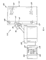
Figure 10 is the axonometric drawing according to the electric discharge device of embodiment of the present invention;
Figure 11 is the axonometric drawing according to the electric discharge device of embodiment of the present invention;
Figure 12 is the orthodontic appliance manufacturing approach flow chart according to embodiment of the present invention;
Figure 13 is the orthodontic appliance manufacturing approach flow chart according to embodiment of the present invention;
Figure 14 is the axonometric drawing according to the orthodontic appliance carriage of embodiment of the present invention;
Figure 15 to Figure 19 is an axonometric drawing, illustrates according to the moulding mechanism part of the orthodontic appliance of embodiment of the present invention and the carriage of molding;
Figure 20 is the orthodontic appliance manufacturing approach flow chart according to embodiment of the present invention;
Figure 21 is the orthodontic appliance bracket axle mapping that is superimposed with the bracket slot pattern according to embodiment of the present invention;
Figure 22 is the sketch map according to the orthodontic appliance carriage that is superimposed with the bracket slot pattern of embodiment of the present invention;
Figure 23 is in order to carry out the ASCII fromat digital coding sequence of discharge pattern shown in Figure 22 according to embodiment of the present invention;
Figure 24 is the block flow diagram according to the orthodontic appliance manufacturing approach of embodiment of the present invention;
Figure 25 is the axonometric drawing according to the orthodontic appliance carriage that is superimposed with the bracket slot pattern of embodiment of the present invention;
Figure 26 is the sketch map according to the orthodontic appliance carriage that is superimposed with the bracket slot pattern of embodiment of the present invention; And
Figure 27 is in order to carry out the ASCII fromat digital coding sequence of discharge pattern shown in Figure 26 according to embodiment of the present invention.
The specific embodiment
Following accompanying drawing with reference to the diagram embodiment of the present invention is more fully explained the present invention.Yet the present invention can be with many multi-form enforcements, and should not be interpreted as the example embodiment that is confined to here to be set forth.Identical label is represented identical parts in the literary composition.Band " ' " symbol, then be illustrated in the optional embodiment similarly parts.
Extremely shown in Figure 27 like Fig. 1; Embodiment of the present invention has advantageously provided a kind of new system, program product and method; Utilize electric discharge machining method (electricaldischarge machining) to process orthodontic appliance or its a part of characteristic; And, in the specific embodiment, use the various characteristics of wire spark erosion technique " cutting " or shaping utensil.The meaning of " CAD " is including, but not limited to any of computer-aided design and all technological.The meaning of " CAM " is including, but not limited to any of computer aided manufacturing and all technological.The meaning of " CNC " or " Machine-Tool Control " is including, but not limited to any of computer numerical control (CNC) and all technological, when relating to manufacturing machine and system, including, but not limited to rapid molding device and system.The meaning of " cutting " comprises carries out galvanic corrosion.The meaning of " EDM " or " EDM-ing " is including, but not limited to any of spark machined (edm) and all technological.Term " 3D " refers to three-dimensional.Be used for describing the vocabulary of the present invention and different embodiments thereof in this description, not only should understand, and comprise and exceeding outside the general sense, in this manual the specific meanings of aspects such as the structure of record, material or effect according to implication as the one of which.
As depicted in figs. 1 and 2; The embodiment of making or make the system 30 of orthodontic appliance can comprise virtual orthodontic appliance design computer 31, and virtual orthodontic appliance design computer 31 has processor 33, with processor 33 bonded memorizeies 35 and be stored in orthodontic appliance in the memorizer 35 product 37 of designing program.The orthodontic appliance product 37 of designing program can comprise instruction, to receive patient's dentition data that known by one of skill in the art usually several different methods obtains; And; The orthodontic appliance product 37 of designing program can comprise instruction; With in response to received patient dentition data; The dimensions of virtual of design orthodontic appliance 41 is represented (virtual dimensional representation), and the dimensions of virtual of orthodontic appliance 41 representes to limit virtual orthodontic appliance design data.
Extremely shown in Figure 7 like Fig. 4; Orthodontic appliance 41 comprises customization arch wire 43 and a plurality of accurate customization carriages 45; Each accurate customization carriage 45 comprises pallet body 47, the tray plate 49 that links to each other with pallet body 47 and in pallet body 47, has bracket slot 51,53 that the carriage groove has width 55.Pallet body 47 can also comprise the carriage wing 57, carriage hook 59, and can also comprise other design features that those skilled in the art are known.Opening bracket slot 51 comprises opening surface end 61, closed substrate 63 and two sides 65,66 of between opening surface end 61 and closed substrate 63, extending.Opening bracket slot 51 (referring to Fig. 4 and Fig. 6) can also comprise from the side the horizontal expansion part of 65,66 one or both of beginnings; This horizontal expansion part is adjacent with substrate 63; And extend into pallet body 47, form the portion that is sunken into 67 that width surpasses groove width 55 width.Part can be arciform near the opening surface end 61 of pallet body 47, perhaps can have more smooth shape.The side 65,66 of bracket slot 51 and the surface that substrate 63 can have general planar, and accordingly, for example the dimensional tolerance along groove width 55 can preferably be low to moderate about 8 microns less than 30 microns.Closing end (bobbin) bracket slot 53 (referring to Fig. 5 and Fig. 7) can comprise closing face end 69, and is in addition similar with opening bracket slot 51.Just, closing end bracket slot 53 also comprises substrate 63 ', a pair of side 65 ', 66 ', width 55 ', and can comprise the portion of being sunken into 67 '.Likewise, carriage bobbin groove 53 can preferably be low to moderate about 8 microns less than 30 microns along the tolerance of its each groove width 55 '.
As shown in Figure 8, system 30 can also comprise mould molding device 71, and as well known to those skilled in the art, mould molding device 71 can utilize different techniques, forms mould 73 such as quick molding method, thereby is used for making customization carriage 45.Multiple rapid shaping technique can comprise for example stereolithography, laminated solid mass manufacturing (laminatedobject), selective laser sintering, fusion sediment molding manufacturing technology, duplicating solidified forming (solid ground curing) and three-dimensional ink-jet printing, only lists several kinds of manufacturing technologies at this.According to the embodiment of the present invention, mould 73 can form pallet body 47 and tray plate 49 simultaneously.Mould 73 is set to hold carriage moulding material 75, and dispensing mechanism 77 is set to carriage moulding material 75 is distributed to mould 73.In embodiments of the present invention, the optional name that proposes like people such as Wiechmann is called the United States Patent(USP) No. 6,776 of " Modular System forCustomized Orthodontic Appliances "; Described in 614; The full content of this patent is incorporated this paper into by reference at this, uses rapid shaping technique, takes this; Through patient's dental impressions is carried out 3-D scanning; Form the computer-aided design of carriage 45 (pallet body 47 and tray plate 49), make the for example wax or the resin mould of carriage 45, use this model to form the mould 73 (for example cement mould) of carriage 45 then.Each mould 73 has usually: die cavity 79 is used to form each carriage 45, and when carriage moulding material 75 is placed in one, forms the circumference of pallet body 47 and tray plate 49; And runner 81, the circumference of stub bar 83 (referring to Fig. 9) when forming 75 fillings of carriage moulding material.Be clearly shown that like Figure 14 when profiled member was taken out, each molding pallet body 47 can link to each other with stub bar 83 from mould 73.
As depicted in figs. 1 and 2; System 30 can also comprise data handling machine 91; Data handling machine 91 is arranged to for example communicate by letter with virtual orthodontic appliance design computer 31 through computer network 93; And data handling machine 91 has memorizer 95 and is stored in the computer aided manufacturing program product 97 in the memorizer 95.Computer aided manufacturing program product 97 can comprise instruction; With in response to virtual orthodontic appliance design data; Carry out the derivation operation of electric discharge device control instruction, this electric discharge device control instruction can be read by lathe, to carry out the formation operation of bracket slot 51,53.Just, the electric discharge device control instruction can comprise the instruction of execution along the discharge pattern making operation of bracket slot 51,53 circumferences extension.Can also be included in the instruction and form the operational order that standing part that bracket slot 51,53 makes pallet body 47 and stub bar 83 simultaneously separates.Should be noted that according to the embodiment of the present invention virtual orthodontic appliance design data can artificial input data's process computer 91, perhaps, artificially receive data from data handling machine 91.When design feature when for example bracket slot width 55,55 ' is described by few parameters, can make in this way.If design feature characterizes more complex features, so, the design input that is provided is more suitable from 31 in virtual orthodontic appliance design computer.Should be noted that memorizer 95, together with the memorizer of other descriptions, can comprise volatibility well known by persons skilled in the art and nonvolatile memory, comprise, for example RAM, ROM and disk or CD are only listed several kinds.The electric discharge device control instruction that should also be noted that the computer aided manufacturing program product can become the form of microcode, program, subprogram and symbolic language, and the particular group or the cohort of orderly operation is provided, and is used for the function of control hardware and guides its operation.According to the embodiment of the present invention, instruction especially clearly is suitable for the numerical control device use.
As depicted in figs. 1 and 2; System 30 also comprises spark machined mechanism 101; Use for example RS-232-C serial communication port or other communication medias well known by persons skilled in the art, through for example computer network 93, spark machined mechanism 101 communicates by letter with data handling machine 91.Spark machined mechanism 101 can comprise the controller 103 with memorizer 105, for example, machine control unit, it can provide computer numerical control (CNC).Controller 103 can also comprise: user input apparatus or device well known by persons skilled in the art; And being stored in the DCP product 107 in the memorizer 105, DCP product 107 can comprise the reception of execution electric discharge device control instruction or the instruction of input operation.Controller 103 can also comprise control sequence product 109, and control sequence product 109 comprises the instruction of deriving control signal in response to the electric discharge device control instruction that is received, and wherein control signal is transmitted the electric discharge device control instruction.It should be noted that; According to the embodiment of the present invention; Communicate by letter between controller 103 and the data handling machine 91; As selection, also can be through using the for example artificial data transmission of portable computer readable media, controller 103 receives (input) electric discharge device control instruction from data handling machine 91.
Like Figure 10 and shown in Figure 11, spark machined mechanism 101 can also comprise electric discharge device 111,111 ', and electric discharge device 111,111 ' has discharging electrode assembly 113,115 (comprising electrode 117,119).Typical DC power supply and the spark controller that is electrically connected with DC power supply (not shown) provide the high-frequency impulse ripple, between electrode 117,119 and the part of pallet body 47 adjacent to electrode 117,119, form corresponding a string altofrequency spark discharge arc.Electric discharge device 111,111 ' electrode for example can adopt two kinds of forms, wire electrospark electrode or wire electrode 117 (referring to Figure 10) and die sinking sparking electrode (die-sinker-electrical discharge electrode) 119 (referring to Figure 11).
Shown in figure 10, electric discharge device 111 uses wire electrode 117, and the electrode assemblie 113 of electric discharge device 111 comprises: hold the filament-feeding tray of wire electrode 117 unused portions or around axle 121, when pattern, supply wire electrode 117 continuously; And hold that the wire electrode was used the receipts silk dish of part or around axle 123, the wire electrode of supplying with from filament-feeding tray 121 in the time of will forming bracket slot 51 through pattern collects, and to wire electrode 117 tension force is provided.Being arranged in filament-feeding tray 121 and receiving between the silk dish 123 is to supply silk positioning disk 125 and receive a silk positioning disk 127.During cutting operation, wire electrode 117 is seen off from filament-feeding tray 121 is stable, and remains on and supply silk positioning disk 125 and receive between the positioning disk 127.Wire electrode 117 makes water as its electrolyte usually, can moisture be sent through the nozzle (not shown) of arranging adjacent to pallet body 47.Can select the electrode negative polarity to improve manufacturing speed.Also can select electrode straight polarity to produce meticulousr bracket slot surface.Also can the two be combined to use according to required.
According to the embodiment of the present invention, electric discharge device 111 comprises that electric discharge device drives platform 129, as understood by one of ordinary skill in the art; For example; In response to control signal, use motor or DC motor (not shown), make electric discharge device drive platform 129 and be suitable in X-Y plane, moving; Contact pallet body 47 and wire electrode 117 are arranged to discharge, thereby accomplish pattern to form bracket slot 51,53.According to another embodiment of the present invention, for example, in response to control signal; Use motor or DC motor (not shown); As understood by one of ordinary skill in the art, make to supply silk positioning disk 125 and receipts silk positioning disk 127 in X-Y plane, to move, accomplish pattern with location wire electrode 117.According to the embodiment of the present invention, can further independently arrange to supply silk positioning disk 125 or receive silk positioning disk 127, thereby can form various geometries non-parallel, non-planar surface.Should be noted that in response to control signal, via positioning disk 125,127 the two or one of which, or wire electrode 117 is moved, pallet body 47 and stub bar were opened in 83 minutes via driving platform 129.
Shown in figure 11; Electric discharge device 111 ' uses die sinking sparking electrode 119; The electrode assemblie 115 of electric discharge device 111 ' can comprise pressure head (ram) (not shown), and when making bracket slot 53, pressure head extends with adjacent with the body of carriage 45 electrode at the bore portion that forms pattern.Should be noted that the part that can use and receive silk dish 125 unconnected wire electrodes 117 is used as the die sinking electrode, thereby replace using specific die sinking electrode 119.Should be noted that according to the embodiment of the present invention other manufacturing approaches for example comprise, pass pallet body 47 and get out the beginning hole, perhaps,, pass pallet body 47 and form the beginning hole, also all within the scope of the invention as the part of forming processes.No matter make and how to form the beginning hole; In case formed the beginning hole of passing pallet body 47, just can the end of wire electrode 117 be connected with receipts silk dish 125, thereby play aforesaid effect; So that form bracket slot 53 with the bobbin form, hereinafter is described.
To shown in Figure 27, embodiment of the present invention also comprises the method for making orthodontic appliance like Fig. 1.For example; Shown in figure 12; According to the embodiment of the present invention, the method for making orthodontic appliance can comprise: receive patient's dentition data (square frame 141), patient's dentition data obtain through for example using technology well-known to those skilled in the art to carry out patho-occlusion inspection/diagnosis; According to the patient's dentition data that received, the dimensions of virtual of design orthodontic appliance is represented (square frame 143); Then, make orthodontic appliance (square frame 145).For example, in the orthodontist clinic, orthodontist or other medical experts check the patient, are used to judge the necessary data of status of patient to compile, and open the prescription of suitable processing, and specify the orthodontic appliance characteristic of implementing this processing.Can use the physical mask that forms dummy model, make the physical model that comprises maxillomandibular upper jaw bone model of patient and mandibular bone model respectively.Selectively, can use various scanning techniques directly to form dummy model.No matter adopt what method, dummy model can be used for forming the dentition data together with explaining the prescription of processing that the patient applies and handling the result who reaches thus.Can be with this transfer of data to the appliance design manufacturer; There; By means of computer, can realize the design of custom orthodontic appliances 41, employed computer does; For example virtual orthodontic appliance design computer 31, work station or other data processors well known to those skilled in the art, three dimensional virtual models that wherein can the store patient dentition and handle planning software or be used for moving tooth to confirm the program product of completing place at dummy model.
Orthodontic appliance 41 can comprise customization arch wire 43 and a plurality of accurate customization carriages 45, tray plate 49 and the bracket slot in the pallet body 47 51,53 that each accurate customization carriage 45 comprises pallet body 47, links to each other with pallet body 47.Can use multiple arch wire manufacturing system and method; Such as; The name that proposes people such as Rubbert is called (full content of this patent is incorporated this paper into by reference at this) described in the United States Patent(USP) No. 6,928,733 of " Method and Systemfor Customizing an Orthodontic Archwire "; Process the custom precision arch wire 43 that is arranged in the bracket slot 51,53; To form accurate interface, aspect the bracket slot width dimensions, accurate interface for example can provide smaller or equal to 20 microns and be low to moderate 8 microns combined tolerances.Arch wire 43 is formed by rustless steel, Ni-Ti base alloy, titanium-niobium-base alloy or titanium-molybdenum-base alloy usually, but also can use various other materials well known to those skilled in the art to process.Carriage 45 is processed by rustless steel, titanium or titanium-base alloy usually, but also can be processed by various other materials well known to those skilled in the art.
Can adopt the several different methods that forms virtual bracket base plate and pallet body.The name that people such as Wiechmann propose is called the United States Patent(USP) No. 6 of " Modular System for CustomizedOrthodontic Appliances "; 776; 614 full content is incorporated this paper into by reference at this; The dimensions of virtual of wherein having described design orthodontic appliance 41 is represented the method for (be used for making carriage 45), comprising: the help by means of the computer in the virtual description of visit carriage characteristic storehouse is the system and method for independent patient's design customization orthodontic brackets 45.For example,,, can directly derive the tray plate geometry, to produce the tray plate 49 that roughly coincide with dental surface shape according to the numeral of patient's tooth according to a kind of method.According to another method of describing by people such as Wiechmann; Adopt software algorithm; Through analyzing the curvature of dental surface; Automatically or semi-automatically calculate suitable tray plate area, and confirm even as big as covering the surface of quite a lot of curvature characteristic, thereby can by hand carriage 45 reliably be arranged on the dental surface.This algorithm can for example begin from predetermined base plate size.The dental surface that is covered by this base plate size has at least one virtual " pier (knoll) " of the part of dental tissue convexity relatively on every side with forming, because complete smooth dental surface can not be offered help for the carriage distinct configuration.As long as couple together with the edge of continuous surface, just can calculate the volume of pier with base plate with any mode easily.The curvature of dental surface is more little, and pier is just smooth more, and its volume is more little.If the volume of " pier " is no more than predetermined value, amplify this base plate automatically by predetermined value, based on such thinking: volume might comprise enough protruding dental features more greatly more.Volume calculated once more.Continue and to circulate, obtain the minimum volume value until each base plate.This is the example approach about this automatic algorithms.According to the principle of telling about, select other approach easily here.
Tray plate 49 also can be designed to conform to the geometry of patient's tooth away from the part of patient's tooth.Can also design pallet body 47 and it is combined with tray plate 49.For example, set up the storehouse of pallet body 47 in advance, and it is stored in the computer allowing selects at any time, yet, also can easily customize pallet body 47 to satisfy needs of patients.Also can design bracket slot 51,53 according to needs of patients.For example, can bracket slot 51,53 be designed to locate with the geometry of patient's tooth.Bracket slot 51,53 can become following form: extend into the opening groove 51 on pallet body surface, perhaps, penetrate the closing end groove 53 that pallet body 47 forms bobbin.This manufacturing approach advantage is, corresponding to the only angle of rotation of 0.7 degree that calculates, can and can make that tolerance is low to reach about 8 microns less than 30 microns along the bracket slot width of any one type of groove 51,53 55,55 ' tolerance (for example).For the tolerance of opening groove up to 40 microns and the tolerance of closing end groove up to for 40 microns to 100 microns the prior art, this is a significant improvement.This precision can more help obtaining more to meet the predetermined finishing that requires and handle.
In addition, bracket design can comprise other accessories, such as the carriage wing 57 or carriage hook 59.In case combined bracket base plate 49, pallet body 45 are accomplished with the three dimensional design of other adnexaes, and other each carriages 45 that form orthodontic appliance are repeated this processing.
Shown in figure 13, according to the embodiment of the present invention, the method for making orthodontic appliance can comprise uses the various forming techniques of knowing and understanding like those skilled in the art.Just, these methods can comprise that perfusion, injection or additive method send carriage moulding material 75 to mould 73 (square frame 151).Mould 73 (referring to Fig. 8) can have the die cavity 79 that is used for each carriage 45, and when in die cavity 79, placing carriage moulding material 75, die cavity 79 limits the circumference of pallet body 47 and tray plate 49.In mould 73, for example, independent runner or cast gate 81 are connected to each die cavity 79, thereby provide independent passage to be used for sending carriage moulding material 75 to each die cavity 79.When filling with carriage moulding material 75, each runner 81 forms stub bar 83.According to the embodiment of the present invention, when carriage moulding material 75 solidifies and from mould 73, take out carriage 45, each pallet body 47 of molding keep linking to each other (referring to Fig. 9 and Figure 14 to Figure 19) with stub bar 83.When stub bar 83 is linked a time-out, stub bar 83 forms so-called casting tree (mold tree).
According to the embodiment of the present invention, the method for manufacturing orthodontic appliance can comprise the automatic process technology of use.Just; The method of making orthodontic appliance 41 can comprise: for example can use data handling machine (like data process computer 91) dimensions of virtual of bracket slot 51,53 from pallet body 47 to represent the let-off gear(stand) control instruction; Computer comprises software or program product; Like the computer aided manufacturing program product 97 (referring to Fig. 1) of previous description, be used for clear and definite indication device control instruction (square frame 153).Operation below the device control instruction is described: form the pattern of extending along bracket slot 51,53 circumferences, thereby form accurate interface with arch wire 43, wherein, pattern can be customized to the relative dimensions approximate match with preliminary election custom precision arch wire 43.The device control instruction can offer the controller of carriage manufacturing installation (like electric discharge device 111,111 '), for example controller 103 (square frame 155) through manual type or through computer network.Then, use the controller 103 that for example transmits control sequence product 109,, derive the control signal (square frame 157) of transmitting the electric discharge device control instruction in response to the electric discharge device control instruction that is received.Then, carry out the discharge pattern, to form bracket slot 51,53 (square frame 159) in response to control signal.
Shown in figure 20; According to the embodiment of the present invention, bracket slot is under the situation of opening bracket slot 51, and the method for making orthodontic appliance 41 can comprise in response to control signal carries out the discharge pattern; To form bracket slot, like Figure 21 and shown in Figure 22.In opening bracket slot structure; Bracket slot 51 has opening 61, closed substrate 63 and two sides that separate 65,66; Extend between substrate 63 and opening 61 side 65,66, and, for example; Bracket slot 51 can form the inner surface that makes its orientation be parallel to tooth to adapt to, and makes carriage position according to the roughly orientation of tray plate 49 and/or aligns.Just, can make bracket slot 51 orientation be roughly parallel to orientation, tray plate geometry or the two of dental surface.Similarly, according to the embodiment of the present invention, pallet body 47 can have the shape that roughly conforms to the shape of corresponding tooth.
According to the embodiment of the present invention, utilize spark machined mechanism 101 " cutting " in pallet body 47 to process bracket slot 51, spark machined mechanism 101 comprises the electric discharge device 111 (referring to Figure 10) that wire electrode 117 is housed.Electric discharge device controller 103 receiving system control instructions are to form discharge pattern (square 171); The device control instruction is perhaps directly from the user, and perhaps being connected through the communication with data handling machine 91 or system's (providing a description the device control instruction that electrode 117 or carriage 45 move) provides.For example; Data handling machine 91 can have computer aided manufacturing program or code 97; Computer aided manufacturing program or code 97 can receive self-virtualizing orthodontia device to design a calculating machine 31 (comprise orthodontia design program) or from the input of other forms of computer-aided design system; Perhaps, computer aided manufacturing program or code 97 can receive the input of designing program or self staying other computer-aided design systems in the data handling machine 91 with the computer aided manufacturing program from orthodontia.According to the embodiment of the present invention; Be similar to the device control instruction of using artificial operator programming to create; Computer aided manufacturing program 97 can form device control instruction (for example computer numerical control (CNC) program); G code level program (square frame 173) for example shown in figure 23 is as understood by one of ordinary skill in the art.As stated, can with comparalive ease this code be sent to electric discharge device controller 103, with control treatment discharge pattern (square frame 175).
After the molding, carriage 45 can be configured to set via the casting that stub bar 83 links to each other.After mould 73 takes off carriage 45, each carriage 45 and the stub bar 83 that is associated are arranged in electric discharge device drive on the platform, with in the pallet body of each carriage " cutting " go out bracket slot, and carriage 45 set from casting takes off.Arranging casting tree (square frame 177) afterwards adjacent to electrode 117, pattern (square frame 179) can begin to discharge.As well-known to those skilled in the art, initially carry out pattern processing and can carry out with manual mode, perhaps through using pick off to carry out with automated manner through the electric discharge device operator.According to the embodiment of the present invention, the electric discharge device driving platform 129 that transports the casting tree can be located each pallet body 47 to contact with 117 discharges of wire electrode separately.According to another embodiment of the present invention, this is to move completion via the positioning disk that is associated 125,127.
When the discharge pattern begins; First carriage 45 on the casting tree of location makes in starting point, and for example the starting point P0 shown in Figure 21 (as is known to the person skilled in the art; This program with device 101 is relevant zero point) locate first carriage 45 suitably adjacent with wire electrode 117 (square frame 181).In addition, filament-feeding tray 121 beginning of holding wire electrode 117 unused portions provides wire electrode 117 continuously, crosses the receipts silk dish 123 partly wire electrode 117 from filament-feeding tray 121 that begins to collect and hold wire electrode 117 usefulness.Also make high frequency electric flow through wire electrode 117; And supply dielectric fluid (not shown); Make between wire electrode 117 and the pallet body 47 that the voltage in the gap can the ionization dielectric fluid, and allow " spark " on pallet body 47, to carry out the washout reason, to form bracket slot 51.
According to the embodiment of the present invention, in response to the device control instruction, position driving platform 129, and then pallet body 47 is positioned, with first path (leg) L according to pattern
1Translation carriage 45 makes wire electrode 117 with pallet body 47 electric interlock rather than directly contact.At a P
1, make electrode 117 and pallet body 47 electric interlock, corrode and handle beginning (square frame 183), a part of fusion on carriage 45 surfaces or evaporation.Then, the L along the path
2 Translation pallet body 47, the expectation starting point P of first side 65 in arriving bracket slot 51
2Effectively, this beginning part of pattern, the particularly second path L
2, can make pattern roughly to extend along the part of pallet body 47 outer surfaces with the mode of first side, 65 traversed bies, go forward side by side into the part of stub bar 83.
Then, the L along the path
3The desired depth of translation pallet body in reaching pallet body 47 forms the length (square frame 185) of first side 65.Then, the L along the path
4The lateral depth of translation pallet body 47 expectation in arriving pallet body 47 forms the horizontal expansion part that extends into pallet body from first side.Then, the L along the path
4Retract pallet body 47, and along the path L
5The lateral depth of translation expectation in arriving pallet body 47 forms bracket slot substrate 63, and forms the horizontal expansion part (square frame 187) that extends into pallet body from second side 66.Then, the L along the path
5Retract the starting point P that pallet body 47 is expected in arriving pallet body
3, to begin to form second side 66.The horizontal expansion that protrudes in first side 65 and second side 66 partly constitutes bracket slot and is sunken into portion 67 (square frame 189).Then, the L along the path
6Translation pallet body 47 is until arriving bracket slot pattern end point P
4(common starting point P adjacent to first side 65
1Layout), form the length (square frame 191) of second side 66.It should be noted that; Although be depicted as parallel to each other; But first side 65 and second side 66 also can form acute angle with the substrate 63 of bracket slot 51; Make two sides that separate 65,66 from bracket slot substrate 63 to the bracket slot opening 61 convergence modes extend, perhaps 63 convergence modes are extended from bracket slot opening 61 to the bracket slot substrate.
Then, the L along the path
7 Translation pallet body 47 is until leaving stub bar 83, thereby pallet body 47 is effectively separated with stub bar 83, thereby effectively separates (square frame 193) with the casting tree.If the pallet body design comprises the carriage wing 57 shown in Fig. 4 and Figure 21; Then further translation pallet body 47; Make pattern extend, thereby form the groove side surface of the carriage wing 57, pallet body 47 is separated with stub bar 83 along the groove side surface of the carriage wing 57.Should be noted that as discussed previously, also can guided in translation dish 125,127, rather than translation pallet body 47, carry out preceding text operation and hereinafter operation.
Shown in figure 24; According to the embodiment of the present invention; At bracket slot is to pass under the situation of closing end bracket slot 53 of guide groove or bobbin of pallet body 47; The method of making orthodontic appliance 41 can comprise in response to control signal carries out the discharge pattern to form bracket slot, like Figure 25 and shown in Figure 26.In the tubular brackets groove structure, bracket slot 53 has closed circumference and extends through pallet body 47.Be similar to opening bracket slot 51, for example, tubular brackets groove 53 also can form the interior surface orientations that is suitable for being parallel to tooth, makes pallet body 47 according to the roughly orientation positions of tray plate 49 or be positioned this orientation.Just, can make bracket slot 53 orientation be roughly parallel to orientation, tray plate geometry or the two of dental surface.Similarly, the pallet body 47 that has a tubular brackets groove 53 also can have the shape that roughly conforms to corresponding teeth patterning.
According to the embodiment of the present invention, in response to control signal, carry out the first discharge pattern, to form carriage bobbin 53.Pattern extends along the circumference of carriage bobbin 53, and the relative dimensions coupling of the arch wire 43 that can be customized to and select in advance, thereby forms accurate interface with arch wire 43.Use the combination of die sinking electrode for example 119 and wire electrode 117, in pallet body 47 " cutting " go out carriage bobbin 53.As discussed previously; Electric discharge device controller 103 can the receiving system control instruction; To form discharge pattern (square 201); Those instructions shown in Figure 27 of device control instruction, perhaps directly from the user, perhaps being connected through the communication with data handling machine 91 or system's (providing a description the device control instruction that electrode moves) provides.Selectively, other measures that can know by one of skill in the art form the beginning hole.After the casting tree of location (square frame 203), perhaps through electric discharge device 101 operator's manual methods, perhaps through using the automated manner (as is known to the person skilled in the art) of pick off, pattern (square frame 205) can begin to discharge.
When beginning to discharge pattern, first carriage 45 that need cut out bobbin on the casting tree is positioned, make in starting point, for example the starting point TP shown in Figure 25
0(it can be set at the program of electric discharge device 111 ' and be associated zero point) located, and carriage and wire electrode 117 are suitably adjacent.If be not pre-formed beginning duct 130 (square frame 207), can use die sinking electrode 119 or discontinuous one section wire 117 to process or scribe beginning duct 130 (square frame 209).Make high frequency electric flow through electrode 117,119; And supply dielectric fluid; Make between electrode 117,119 and the pallet body 47 that the voltage in the gap can the ionization dielectric fluid, handle, thereby be formed for the beginning duct of carriage bobbin 53 on pallet body 47, to carry out to corrode.Scribe duct 130 so that wire electrode 117 can normal extension after, at starting point TP
0Duct 130 (square frame 211) is passed with wire electrode 117 by the place.The speed of selecting according to the user or with material fixed speed; Filament-feeding tray 121 beginning of holding wire electrode 117 unused portions provides wire electrode 117 continuously, crosses the receipts silk dish 123 partly wire electrode 117 from filament-feeding tray 121 that begins to collect and hold wire electrode 117 usefulness.As discussed previously, also make high frequency electric flow through wire electrode 117, and supply with dielectric fluid, handle on pallet body 47, to carry out to corrode, thereby form the carriage bobbin.
According to preferred implementation of the present invention, in response to the device control instruction, according to the first path TL of pattern
1The translation pallet body makes wire electrode 117 electroerosion pallet body materials, up to the expectation circumference part (square frame 213) of carriage bobbin 53, for example, at initial circumference starting point TP
1The place.Then, the TL along the path
2Translation pallet body 47 is until the expectation starting point TP that arrives first side 65 '
2Then, the TL along the path
3Translation pallet body 47 is until the desired length that arrives carriage bobbin 53.Then, the TL along the path
4Translation pallet body 47 is until the desired width 55 ' that reaches bracket slot 53.Then, the TL along the path
5Translation pallet body 47 is until the desired length that reaches second side 66 '.Then, translation pallet body 47 is until arriving initial circumference starting point TP
1, the circumference (square frame 215) of completion bracket slot 53.Then, wire electrode 117 is taken out (square frame 217) in carriage bobbin 53.It should be noted that; Although be depicted as parallel to each other; But first side 65 ' and second side 66 ' also can form acute angle with the bracket slot substrate of groove 53 63 ', make two sides that separate 65 ', 66 ' from bracket slot substrate 63 ' or extend with the convergence mode to bracket slot substrate 63 '.In addition, be similar to opening bracket slot 51, as discussed previously, can extend one or the more length or the width of multipath, make the length of cutting surpass the length or the width of carriage bobbin 53, thereby form the portion that is sunken into.
According to the embodiment of the present invention, in response to control signal, can also carry out the second discharge pattern, so that pallet body 47 was opened (referring to Figure 25 to Figure 27) in 83 minutes with stub bar.During the beginning second discharge pattern (square frame 221), detent bracket body 47 makes at starting point (starting point S for example shown in Figure 25
0) locate carriage 45 suitably adjacent with wire electrode 117 (square frame 223).Then, according to the first path LP of pattern
1 Make pallet body 47 change positions.Then, the LP along the path
2 Translation pallet body 47 makes pallet body 47 effectively separate (square frame 225) with stub bar 83 and then with the casting tree until leaving stub bar 83.
It should be noted that; Although the mode with the repertoire system is illustrated embodiment of the present invention, it will be appreciated by those skilled in the art that mechanism of the present invention and/or aspect can be distributed as the form of the computer-readable medium of instruction; Be employed in uniprocessor, multiprocessor etc. and go up the various ways of operation; And, no matter adopt the signal bearing medium of which kind of particular type to come actual this distribution that realizes, the present invention is suitable equally.The example of computer-readable medium is including, but not limited to the nonvolatile, hard-coded type medium, such as read only memory (ROM), CD-ROM and DVD-ROM; Perhaps EEPROM (EEPROM); But the record type medium is such as the memorizer of floppy disk, hard disk drive, CD-R/RW, DVD-RAM, DVD-R/RW, DVD+R/RW, flash memory and other newtypes; And transmission type media, be connected with analogue communication such as numeral.
To shown in Figure 27, embodiment of the present invention comprises computer-readable medium like Fig. 1, can be read by the computer of making or make orthodontic appliance.For example; According to the embodiment of the present invention; Provide and contained one group of computer-readable medium that instructs, when this organizes instruction by the computer execution, make computer accomplish following the operation: the dimensions of virtual of the bracket slot 51,53 in the pallet body 47 of reception orthodontic appliance 41 carriages 45 is represented; And, represent and/or user's input the let-off gear(stand) control instruction in response to the dimensions of virtual of bracket slot 51,53.The device control instruction comprises those instructions, to accomplish along the formation operation of the discharge pattern of bracket slot 51,53 circumferences extension, has the precision of the relative dimensions approximate match of enough and preliminary election arch wire 43, thereby forms accurate interface with arch wire 43.
Particularly; For opening groove 51, perhaps preferably shown in figure 21, for example; The device control instruction can comprise the instruction of those operations below completion: detect or judge the position of formation pattern starting point on the pallet body 47, with the beginning spark machined; Along in the pallet body outer surface with the adjacent part of groove 51 openings, the beginning of pattern is partly extended; Cutting puts in the passage of pallet body 47, to form first side 65 of groove 51; Cut the passage that partial lateral is at least extended in first side 65, to form carriage substrate 63; And, make cutting channel extend to the surface of pallet body 47, forming second side 66, and accomplish the formation of bracket slot 51.Instruction can also comprise those accomplish below the instruction of operation: adjacent with the substrate 63 of bracket slot 51 from the side 65,66 that separates one or both of, form the horizontal expansion part that puts in pallet body 47, be sunken into portion 67 thereby form bracket slot.Instruction can also comprise those and accomplish the instruction of following operation: make the groove side surface extension of the part of pattern along the carriage wing 57, thereby form the groove side surface of the carriage wing 57.Advantageously, select pattern according to the embodiment of the present invention,,, make separating of pallet body 47 and relevant stub bar 83 through the completion of bracket slot 51 or the completion of cutting the carriage wing 57 groove side surfaces if be suitable for.
For closing end groove 53, perhaps preferably shown in figure 25, for example, the device control instruction can comprise the instruction of those operations below completion: detect or judge the position of formation pattern starting point on the pallet body 47, with the beginning spark machined; The beginning of pattern is partly extended to and the bracket slot 53 interior adjacent points of circumference; Make the interior circumference extension of pattern, thereby form bracket slot 53 along bracket slot 53.Instruction can also comprise those accomplish below the instruction of operation: from the side one of 65 ', 66 ', adjacent with the substrate 63 ' of bracket slot 53, form the horizontal expansion part that puts in pallet body 47, be sunken into portion thereby form bracket slot.Should be noted that for the pallet body 47 that is not pre-formed beginning duct 130 instruction can also comprise carries out the instruction that beginning duct 130 forms operation.Instruction can also comprise those and carry out the instruction of following operation: form the position of the second pattern starting point on detection or the judgement pallet body 47, to begin spark machined; And, make second pattern extend through stub bar 83, thereby pallet body 47 is separated with stub bar 83.
According to the embodiment of the present invention; The computer-readable medium that contains one group of instruction is provided; In the time should organizing instruction by the computer execution; Make computer carry out following operation: receive the electric discharge device control instruction, this electric discharge device control instruction is described the dimensions of virtual of the pallet body groove 51,53 in the pallet body 47 of orthodontic appliance 41 carriages 45 and is represented; And, in response to the electric discharge device control instruction, derive the control signal of transmitting the electric discharge device control instruction, to accomplish aforesaid operations.
Specifically the present invention has been carried out quite detailed explanation with reference to the illustrative embodiment of preamble, yet, should be appreciated that as described in the above stated specification, can make multiple modification, change and other changes within the spirit and scope of the present invention.For example, the carriage of the no groove of preceding text description is produced in mould.The additive method of production pretreatment carriage is in above-mentioned technical scope.In addition, for example, preceding text are described bracket slot and are formed according to the device control instruction.In optional embodiment of the present invention; Can use or make up use separately or use other processing methods with the spark machined combination; Comprise the known milling of those skilled in the art, boring, turning, honing, ultrasonic Machining, water under high pressure cutting or pulverizing; Carry out the above-mentioned processing graphic pattern that extends along the bracket slot circumference, so that the customization carriage with the relative dimensions approximate match of arch wire to be provided.
In addition, to those skilled in the art, can carry out the variation (present known variation or the variation of design later on) of unsubstantiality to the present invention's technical scheme required for protection, these variations all are the equivalent replacements in the claim scope.So as far as those of ordinary skills, the conspicuous displacement of carrying out now and later on is all in the scope of institute's limiting part.In addition; Be used for describing the vocabulary of the present invention and different embodiments thereof in this manual; Be interpreted as not only expressing the meaning that defines as the one of which, and outside the meaning of General Definition, also comprise in this manual to structure, material or action carry out specifically defined.
In view of the above; The present invention relates to be used to make the device of orthodontic appliance; This device comprises: virtual orthodontic appliance design computer; The virtual orthodontic appliance design calculate have processor, with the bonded memorizer of processor and be stored in orthodontic appliance in the memorizer product of designing program, the orthodontic appliance product of designing program comprises the instruction that patient's dentition data is received operation, and; Comprise that the dimensions of virtual that aligns abnormal appliance in response to the patient's dentition data that received representes to carry out the instruction of design operation; The dimensions of virtual of orthodontic appliance is represented defining virtual orthodontic appliance design data, and orthodontic appliance comprises customization arch wire and a plurality of accurate customization carriage, and each accurate customization carriage comprises faying face and bracket slot towards tooth; Layout is to form the mould molding device of each carriage, and it comprises mould (arranging to hold the carriage moulding material) and dispensing mechanism (arranging so that carriage moulding material branch is fed into mould), and mould has the die cavity of each carriage that is used for a plurality of carriages; When in die cavity, being placed with the carriage moulding material, die cavity limits the circumference of carriage, and; Mould has with runner; When being full of the carriage moulding material, runner limits the circumference of stub bar, links to each other with stub bar when each molding carriage takes out from mould; Data handling machine; Itself and the compunication of virtual orthodontic appliance design; And have memorizer and be stored in the computer aided manufacturing program product in the memorizer, the computer aided manufacturing program product comprises instruction, to carry out the operation that the electric discharge device control instruction is derived; The electric discharge device control instruction comprises carries out those instructions that pattern forms operation, and the institute's pattern that forms description is represented corresponding to the bracket slot dimensions of virtual of virtual orthodontic appliance design data; And spark machined mechanism, it is communicated by letter with data handling machine, and comprises the controller that has memorizer and be stored in the DCP product in the memorizer; The DCP product comprises carries out the instruction that the electric discharge device control instruction receives operation, and spark machined mechanism also comprises the control sequence product that is stored in the memorizer; This control sequence product comprises instruction, with in response to the electric discharge device control instruction that is received, derives the control signal of transmitting the electric discharge device control instruction; And; Electric discharge device comprises discharging electrode assembly, and this discharging electrode assembly comprises electrode and at least one driver part, in response to control signal; Driver part is suitable for each bracket arrangement is become to contact with electrode discharge; With the formation bracket slot, and driver part is suitable for when forming bracket slot, carriage being separated with stub bar.
Preferably, the electric discharge device control instruction comprises instruction, to carry out the operation that forms discharge pattern (extending along bracket slot).
In addition, preferably, bracket slot comprises opening surface end and closed substrate and two sides that separate of extending betwixt, and wherein, the beginning of pattern part is extended to be substantially transverse at least one lateral mode along the part of carriage outer surface.
Selectively; Bracket slot comprises opening surface end and closed substrate and two sides that separate of extending betwixt; Wherein carriage comprises the carriage wing with groove side surface; And wherein, the part of pattern is extended along the groove side surface of the carriage wing, thereby forms the groove side surface of the carriage wing.
Preferably; Bracket slot comprises opening and closed substrate and two sides that separate of extending betwixt; And wherein, the substrate that pattern is included in bracket slot extends into the horizontal expansion part of carriage one of from the side that separates, is sunken into portion thereby limit bracket slot.
Bracket slot can comprise that opening and closed substrate and two of extending betwixt separate to limit the sides of bracket slot width; Wherein pattern comprises at least one horizontal expansion part; This horizontal expansion part separates the side with the mode adjacent with substrate from corresponding at least one and extends into carriage; Thereby qualification has the bracket slot that is sunken into portion's width and is sunken into portion, is sunken into portion's width and surpasses the groove width.
The electric discharge device control instruction can comprise those instructions, to accomplish the operation that detects pattern starting point formation position on the carriage, with the beginning spark machined.
Electrode can comprise the wire sparking electrode that constitutes the wire electrode, and wherein electrode assemblie comprises filament-feeding tray and receives the silk dish, and this filament-feeding tray holds wire electrode unused portion; So that the wire electrode to be provided when forming pattern continuously, to receive the silk dish and hold wire and used part, to collect the wire electrode that supplies from filament-feeding tray when forming bracket slot forming pattern; And tension force is provided to the wire electrode, thus the cutting surface of general planar is provided, wherein; When arch wire is positioned at bracket slot; Bracket slot and arch wire form bracket slot-arch wire interface, and wherein, the unidimensional at least tolerance in bracket slot-arch wire interface is smaller or equal to about 20 microns (μ m).
Selectively, electrode comprises the die sinking sparking electrode, and wherein electrode assemblie comprises pressure head; When carrying out pattern, to make electrode extension and adjacent with carriage; Forming bracket slot, and wherein, specify the tolerance of this bracket slot on one dimension at least less than 30 microns.
In other words; The system that is used to make orthodontic appliance comprises: digital control data processor, this digital control data processor constitute and have memorizer and the controller that is stored in the control sequence product in the memorizer, and this control sequence product comprises instruction; When the controller execution should be instructed; Make controller accomplish the derivation operation of control figure signal (transmitting the electric discharge device control instruction), in the carriage of orthodontic appliance, forming bracket slot, and carriage is separated with the stub bar that links to each other; And electric discharge device; This electric discharge device is communicated by letter with controller; And have discharging electrode assembly (comprising electrode) and at least one driver part; Driver part is fit in response to digital controlled signal bracket arrangement become to contact with electrode discharge, with the formation bracket slot, and when forming bracket slot, carriage is separated with stub bar.In view of the above, device comprises: controller, this controller have memorizer, are stored in the DCP product in the memorizer and are stored in the control sequence product in the memorizer equally; This DCP product comprises instruction; When the controller execution should be instructed, make controller carry out the reception operation of electric discharge device control instruction, the dimensions of virtual that this electric discharge device control instruction is described bracket slot in the orthodontic appliance carriage is represented; This control sequence product comprises instruction; When the controller execution should be instructed, make controller in response to the electric discharge device control instruction, execution will be transmitted the operation of the control signal derivation of electric discharge device control instruction; And electric discharge device; This electric discharge device is communicated by letter with controller; Electric discharge device has discharging electrode assembly (comprising electrode) and at least one driver part, and driver part is fit in response to control signal bracket arrangement become to contact with electrode discharge, to form bracket slot according to the pattern that limits in advance; This pattern is set at the relative dimensions approximate match with arch wire, thereby forms accurate interface with arch wire.
Orthodontic appliance manufacturing approach according to the present invention may further comprise the steps: the dimensions of virtual according to bracket slot in the orthodontic appliance carriage is represented; Derive the control signal of transfer device control instruction; The device control instruction records carries out the operation of discharge pattern; This pattern is extended along the bracket slot circumference, and is configured to the relative dimensions approximate match with arch wire, thereby forms accurate interface with arch wire; And, carry out the discharge pattern in response to control signal, to form bracket slot.Preferably, the discharge pattern is customized to the relative dimensions approximate match with the preliminary election arch wire.
Before carrying out the discharge pattern, carriage can link to each other with stub bar, and the step of carrying out the discharge pattern comprises from carriage excision stub bar, to separate with stub bar at the carriage that roughly makes simultaneously that forms bracket slot.
Before carrying out the discharge pattern, carriage can link to each other with the stub bar that links to each other with the casting tree, and the step of carrying out the discharge pattern can comprise the step of downcutting carriage from the casting tree.
When bracket slot comprises two sides that separate of opening surface end and closed substrate and extension betwixt; The step of carrying out the discharge pattern may further include following steps: forms adjacent with the bracket slot substrate and extend into the horizontal expansion part of carriage from a side that separates, thereby the qualification bracket slot is sunken into portion.
When bracket slot comprises two sides (separating each other to limit the bracket slot width) of opening surface end and closed substrate and extension betwixt; The step of carrying out the discharge pattern may further include following steps: form adjacent with the bracket slot substrate and extend into the horizontal expansion part of carriage from a side that separates; Thereby qualification has the bracket slot that is sunken into portion's width and is sunken into portion, is sunken into portion's width and surpasses the bracket slot width.
When carriage comprised the carriage wing, the step of carrying out the discharge pattern may further include the step that the part that makes pattern is extended along carriage wing groove side surface, thereby formed the groove side surface of the carriage wing.
When bracket slot comprises opening surface end and closed substrate and during two sides of extending betwixt, the step of carrying out the discharge pattern may further include following step: make pattern begin part along the part of carriage outer surface and be substantially transverse at least one side and extend.In addition, the step of carrying out the discharge pattern can be included in the step that forms acute angle between a side and the bracket slot substrate, makes two sides that separate extend from bracket slot substrate convergence mode.
When bracket slot is the carriage bobbin; The discharge pattern can be the first discharge pattern; Wherein before carrying out the first discharge pattern, carriage links to each other with stub bar, and wherein; This method further comprises the step of carrying out the second discharge pattern in response to control signal, so that carriage separates with stub bar.
Preferably, arch wire customizes, and this method further comprises and form the step be suitable for being arranged in the customization arch wire in the bracket slot, so that bracket slot-arch wire interface forms gap or tolerance on one dimension at least smaller or equal to 20 microns.
Claims (45)
1. system that is used to make orthodontic appliance; Said orthodontic appliance has arch wire and a plurality of carriage; Each said carriage has the bracket slot in tooth faying face and the pallet body, and said system comprises spark machined mechanism, and said spark machined mechanism has discharging electrode assembly and at least one driver part that comprises electrode; Said driver part is suitable for each pallet body is arranged to contact with said electrode discharge; Be used for the said bracket slot of molding, said spark machined mechanism has the device that is used to receive digital control director data
Said system comprises computer, and said computer is suitable for generating said digital control director data according to the data that the dimensions of virtual that limits said orthodontic appliance is represented, it is characterized in that:
Said system comprises moulding mechanism; Said moulding mechanism comprises mould and dispensing mechanism; Said mould is set to hold the carriage moulding material and is suitable for forming each pallet body, and said dispensing mechanism is set to be used for making said carriage moulding material branch to deliver to said mould, and said mould has die cavity; Said die cavity be suitable for each said carriage profile, and constitute profile with the stub bar of the said mould of said carriage molding material fills; Each said stub bar comprises standing part, and said standing part links to each other with the part of pallet body in being arranged in the plane, and perhaps the plane with the open surfaces that will process bracket slot links to each other.
2. system according to claim 1; It is characterized in that: said computer has the memorizer that is associated; Said memorizer is suitable for receiving three-dimensional patient's dentition data; And the data that are suitable for generating the customizing virtual size Expressing that limits said orthodontic appliance, said data part at least come from said patient's dentition data.
3. system according to claim 1 is characterized in that: said driver part comprises holding portion, and the described accommodation section branch is used to hold the standing part that links to each other with said pallet body.
4. the described system of each claim in requiring according to aforesaid right; It is characterized in that: said driver part is suitable for each pallet body and is set to contact with said electrode discharge; Thereby, in the said bracket slot of molding, said pallet body is separated with standing part.
5. according to the described system of each claim among the claim 1-3; It is characterized in that: the said computer of controlling said spark machined mechanism comprises the controller with memorizer and is stored in the DCP in the said memorizer; The instruction that said DCP comprises is used for generating digital control director data signal in response to institute's stored numbers control instruction data, and said digital control director data signal is used for said spark machined mechanism and/or said driver part are controlled.
6. system according to claim 4; It is characterized in that: the said computer of controlling said spark machined mechanism comprises the controller with memorizer and is stored in the DCP in the said memorizer; The instruction that said DCP comprises is used for generating digital control director data signal in response to institute's stored numbers control instruction data, and said digital control director data signal is used for said spark machined mechanism and/or said driver part are controlled.
7. system according to claim 5 is characterized in that: said digital control director data signal comprises the data that are used to control said spark machined mechanism, the pattern that extends along the circumference of said bracket slot with cutting.
8. system according to claim 6 is characterized in that: said digital control director data signal comprises the data that are used to control said spark machined mechanism, the pattern that extends along the circumference of said bracket slot with cutting.
9. according to the described system of each claim among the claim 1-3; It is characterized in that: said bracket slot comprises opening surface end and closed substrate; And two sides that separate of between said two devices, extending; Wherein, said discharging electrode assembly is suitable for being arranged as, and the part transverse at least one said lateral said pallet body outer surface is contacted with electrode discharge.
10. system according to claim 4; It is characterized in that: said bracket slot comprises opening surface end and closed substrate; And two sides that separate of between said two devices, extending; Wherein, said discharging electrode assembly is suitable for being arranged as, and the part transverse at least one said lateral said pallet body outer surface is contacted with electrode discharge.
11. system according to claim 5; It is characterized in that: said bracket slot comprises opening surface end and closed substrate; And two sides that separate of between said two devices, extending; Wherein, said discharging electrode assembly is suitable for being arranged as, and the part transverse at least one said lateral said pallet body outer surface is contacted with electrode discharge.
12. system according to claim 6; It is characterized in that: said bracket slot comprises opening surface end and closed substrate; And two sides that separate of between said two devices, extending; Wherein, said discharging electrode assembly is suitable for being arranged as, and the part transverse at least one said lateral said pallet body outer surface is contacted with electrode discharge.
13. system according to claim 7; It is characterized in that: said bracket slot comprises opening surface end and closed substrate; And two sides that separate of between said two devices, extending; Wherein, said discharging electrode assembly is suitable for being arranged as, and the part transverse at least one said lateral said pallet body outer surface is contacted with electrode discharge.
14. system according to claim 8; It is characterized in that: said bracket slot comprises opening surface end and closed substrate; And two sides that separate of between said two devices, extending; Wherein, said discharging electrode assembly is suitable for being arranged as, and the part transverse at least one said lateral said pallet body outer surface is contacted with electrode discharge.
15. system according to claim 1 is characterized in that: said carriage comprises the carriage wing with groove side surface, and wherein, said driver part is suitable for each carriage and is set to contact with said electrode discharge along said carriage wing groove side surface.
16. according to the described system of each claim among the claim 1-3, it is characterized in that: said electrode comprises the wire sparking electrode.
17. system according to claim 4 is characterized in that: said electrode comprises the wire sparking electrode.
18. system according to claim 5 is characterized in that: said electrode comprises the wire sparking electrode.
19. system according to claim 6 is characterized in that: said electrode comprises the wire sparking electrode.
20. system according to claim 7 is characterized in that: said electrode comprises the wire sparking electrode.
21. system according to claim 8 is characterized in that: said electrode comprises the wire sparking electrode.
22. system according to claim 9 is characterized in that: said electrode comprises the wire sparking electrode.
23. system according to claim 10 is characterized in that: said electrode comprises the wire sparking electrode.
24. system according to claim 11 is characterized in that: said electrode comprises the wire sparking electrode.
25. system according to claim 12 is characterized in that: said electrode comprises the wire sparking electrode.
26. system according to claim 13 is characterized in that: said electrode comprises the wire sparking electrode.
27. system according to claim 14 is characterized in that: said electrode comprises the wire sparking electrode.
28. system according to claim 15 is characterized in that: said electrode comprises the wire sparking electrode.
29. system according to claim 1 is characterized in that: said electrode comprises the die sinking sparking electrode.
30. system according to claim 1; It is characterized in that: on two at least one sides that separates in the side of said bracket slot and in the substrate of said bracket slot, said bracket slot has at least that the one dimension tolerance is 30 microns flat surfaces to the maximum.
31. system according to claim 1 is characterized in that: said bracket slot is a bobbin.
32. a method that is used to make the orthodontic appliance with arch wire and a plurality of carriages, each carriage has the bracket slot in tooth faying face and the pallet body, said method comprising the steps of:
Data according to the dimensions of virtual that limits said orthodontic appliance is represented generate digital control director data signal by computer,
It is characterized in that:
Standing part links to each other with the part of pallet body in being arranged in the plane, and perhaps the plane with the open surfaces that will process bracket slot links to each other,
Through using spark machined mechanism to carry out the spark machined said bracket slot that is shaped, said spark machined mechanism comprises the discharging electrode assembly with electrode,
Comprise by each pallet body of at least one driver part being set to contact with said electrode discharge,
Wherein said spark machined mechanism is by said digital control director data signal controlling.
33. method according to claim 32 is characterized in that: three-dimensional patient's dentition data are provided for said computer, and according to said three-dimensional patient's dentition data, the said dimensions of virtual that is generated said orthodontic appliance by said computer is represented.
34. method according to claim 32; It is characterized in that: said method comprises said pallet body is made for and comprises standing part; And wherein; Make said standing part place the holding portion of said driver part, said pallet body is oriented to towards said spark machined mechanism to process.
35. method according to claim 34 is characterized in that: in the mould that is suitable for forming each carriage that links to each other with stub bar, make said carriage through making the molding of carriage moulding material, said stub bar comprises said standing part.
36. method according to claim 32 is characterized in that: said method comprises through spark machined makes said standing part and said pallet body separation steps.
37. method according to claim 36 is characterized in that: form said bracket slot through spark machined, said standing part is separated with said pallet body.
38. according to the described method of each claim in claim 32 to the claim 37; It is characterized in that: through spark machined; Said groove is processed into and comprises opening surface end and closed substrate and two sides that separate of between said two devices, extending; At least one of said side is provided with the horizontal expansion part of said groove; This horizontal expansion part is adjacent with said bracket slot substrate from one of said side that separates to extend into said pallet body, is sunken into portion to process at least one bracket slot.
39. according to the described method of claim 38, it is characterized in that: said groove is sunken into the width of the width of portion above said bracket slot.
40. method according to claim 32; It is characterized in that: said carriage forms in mould; To comprise the carriage wing with groove side surface, wherein, said driver part is that groove side surface along the said carriage wing contacts with said electrode discharge with each said bracket arrangement.
41. method according to claim 32; It is characterized in that: said bracket slot has bracket slot substrate and at least two sides that separate; Wherein said spark machined forms said side; Between said bracket slot substrate and said side, to form acute angle, make said lateral convergence.
42. method according to claim 32 is characterized in that: said bracket slot is the carriage bobbin.
43. according to the described method of each claim in the claim 32 to 37, it is characterized in that: said spark machined is used the wire sparking electrode.
44. according to the described method of each claim in the claim 32 to 37, it is characterized in that: said spark machined is used the die sinking sparking electrode.
45. according to the described method of each claim in the claim 32 to 37; It is characterized in that: on two at least one sides that separates in the side of said bracket slot and in the substrate of said bracket slot, the surperficial tolerance that said spark machined is processed is less than 30 microns.
Applications Claiming Priority (5)
| Application Number | Priority Date | Filing Date | Title |
|---|---|---|---|
| US76302206P | 2006-01-27 | 2006-01-27 | |
| US60/763,022 | 2006-01-27 | ||
| US11/583,103 US7751925B2 (en) | 2006-01-27 | 2006-10-18 | System to manufacture custom orthodontic appliances, program product, and related methods |
| US11/583,103 | 2006-10-18 | ||
| PCT/EP2007/050847 WO2007085656A1 (en) | 2006-01-27 | 2007-01-29 | System to manufacture custom orthodontic appliances, and related process |
Publications (2)
| Publication Number | Publication Date |
|---|---|
| CN101374473A CN101374473A (en) | 2009-02-25 |
| CN101374473B true CN101374473B (en) | 2012-07-04 |
Family
ID=37964358
Family Applications (1)
| Application Number | Title | Priority Date | Filing Date |
|---|---|---|---|
| CN2007800036092A Expired - Fee Related CN101374473B (en) | 2006-01-27 | 2007-01-29 | System to manufacture custom orthodontic appliances, and related process |
Country Status (8)
| Country | Link |
|---|---|
| US (1) | US7751925B2 (en) |
| EP (1) | EP1976449B1 (en) |
| JP (1) | JP5543112B2 (en) |
| KR (1) | KR101287771B1 (en) |
| CN (1) | CN101374473B (en) |
| BR (1) | BRPI0706965B8 (en) |
| RU (1) | RU2429795C2 (en) |
| WO (1) | WO2007085656A1 (en) |
Families Citing this family (37)
| Publication number | Priority date | Publication date | Assignee | Title |
|---|---|---|---|---|
| US9466151B2 (en) * | 2001-04-13 | 2016-10-11 | Orametrix, Inc. | Bracket-slot-to-wire play compensation archwire design |
| US6776614B2 (en) | 2002-02-13 | 2004-08-17 | Lingualcare, Inc. | Modular system for customized orthodontic appliances |
| US6928733B2 (en) | 2002-11-06 | 2005-08-16 | Lingualcare, Inc. | Method and system for customizing an orthodontic archwire |
| US7240528B2 (en) * | 2004-11-22 | 2007-07-10 | Lingualcare, Inc. | Method and device for shaping an orthodontic archwire |
| WO2008048903A2 (en) * | 2006-10-16 | 2008-04-24 | Jack Keith Hilliard | System for producing orthodontic aligners by cnc machining |
| US7950131B2 (en) * | 2006-12-19 | 2011-05-31 | Jack Keith Hilliard | Robotic system for forming features in orthodontic aligners |
| DE102007014088A1 (en) * | 2007-03-21 | 2008-09-25 | Dreve Prodimed Gmbh | Method for the generative production of individual, dental forms for articulators |
| US20080254403A1 (en) * | 2007-04-10 | 2008-10-16 | Jack Keith Hilliard | System for cnc-machining fixtures to set orthodontic archwires |
| EP2328506B1 (en) * | 2008-07-30 | 2018-11-28 | 3M Innovative Properties Company | Low profile self-ligating orthodontic appliance with clip |
| US20100092907A1 (en) * | 2008-10-10 | 2010-04-15 | Align Technology, Inc. | Method And System For Deriving A Common Coordinate System For Virtual Orthodontic Brackets |
| US8083522B2 (en) * | 2008-10-29 | 2011-12-27 | Inpronto Inc. | Method for tooth implants |
| US20100105011A1 (en) * | 2008-10-29 | 2010-04-29 | Inpronto Inc. | System, Method And Apparatus For Tooth Implant Planning And Tooth Implant Kits |
| US8257080B2 (en) * | 2009-05-05 | 2012-09-04 | 3M Innovative Properties Company | Low profile orthodontic bite corrector |
| CN102232873A (en) * | 2010-04-28 | 2011-11-09 | 黄正和 | Positioning method and structure of dental braces |
| CN101991465B (en) * | 2010-09-10 | 2012-09-26 | 广州瑞通生物科技有限公司 | Manufacturing method of positioning tray and bracket with positioning hook used for manufacturing positioning tray |
| DE102011003892A1 (en) * | 2011-02-09 | 2012-08-09 | Hoang Viet-Ha Julius Vu | Method for producing at least one patient-specific, modularly constructed bracket and associated bracket |
| DE102011003895A1 (en) * | 2011-02-09 | 2012-08-09 | Hoang Viet-Ha Julius Vu | Orthodontic component with a slot and associated component holding device |
| CN102274080A (en) * | 2011-04-28 | 2011-12-14 | 李强 | Tail-end protecting device of fixed appliance |
| EP2914200B1 (en) | 2012-10-30 | 2019-05-22 | University of Southern California | Orthodontic appliance with snap fitted, non-sliding archwire |
| FR3002431B1 (en) * | 2013-02-23 | 2017-12-29 | Robert Duchateau | VESTIBULAR ORTHODONTIC DEVICE |
| EP2967759A4 (en) | 2013-03-15 | 2016-11-09 | 3M Innovative Properties Co | Self-ligating orthodontic appliance |
| DE102013209735A1 (en) * | 2013-05-24 | 2014-11-27 | Dw Lingual Systems Gmbh | A method of making a patient-specific replacement bracket for orthodontic treatment and a bracket made by the method |
| EP3007642B1 (en) * | 2013-06-14 | 2020-02-19 | Robert T. Rudman | Self-ligating orthodontic bracket with rotatable closure member |
| KR101489384B1 (en) * | 2013-06-20 | 2015-02-04 | 이종호 | Lingual orthodontic bracket and the bracket for the personalized production method |
| RU2572185C2 (en) * | 2013-11-15 | 2015-12-27 | Дмитрий Геннадиевич Корж | Lingual individual orthodontic appliance and method for orthodontic treatment taking into account temporomandibular joint parameters |
| EP2881075A1 (en) * | 2013-12-06 | 2015-06-10 | 3M Innovative Properties Company | A method of making customized orthodontic brackets |
| US10098709B1 (en) | 2014-06-24 | 2018-10-16 | Ormco Corporation | Constrained optimization of orthodontic bracket placement and archwire smoothing |
| US20170224444A1 (en) * | 2015-04-06 | 2017-08-10 | Smarter Alloys Inc. | Systems and methods for orthodontic archwires for malocclusions |
| JP2018514285A (en) * | 2015-05-04 | 2018-06-07 | プレミア オーソドンティック デザインズ エルエルエルピー | Orthodontic bracket |
| EP3407825B1 (en) * | 2016-01-29 | 2020-04-15 | 3M Innovative Properties Company | An orthodontic bracket and a method of making an orthodontic bracket |
| CN105769357B (en) * | 2016-02-04 | 2017-01-11 | 北京正齐口腔医疗技术有限公司 | Generation method and device of transfer tray |
| US10828133B2 (en) | 2016-12-02 | 2020-11-10 | Swift Health Systems Inc. | Indirect orthodontic bonding systems and methods for bracket placement |
| JP7145858B2 (en) * | 2016-12-20 | 2022-10-03 | コーニンクレッカ フィリップス エヌ ヴェ | How to provide a manufacturing environment. |
| EP3576667B1 (en) | 2017-01-31 | 2023-12-06 | Swift Health Systems Inc. | Hybrid orthodontic archwires |
| US11612458B1 (en) | 2017-03-31 | 2023-03-28 | Swift Health Systems Inc. | Method of tongue preconditioning in preparation for lingual orthodontic treatment |
| ES2959766T3 (en) | 2017-04-21 | 2024-02-28 | Swift Health Systems Inc | Indirect bonding splint that has several handles |
| US10278794B1 (en) * | 2018-09-28 | 2019-05-07 | 3D Med Ag | Systems and methods for making orthodontic brackets |
Citations (5)
| Publication number | Priority date | Publication date | Assignee | Title |
|---|---|---|---|---|
| EP0290247A2 (en) * | 1987-05-06 | 1988-11-09 | Ormco Corporation | Orthodontic brackets |
| WO1994010935A1 (en) * | 1992-11-09 | 1994-05-26 | Ormco Corporation | Custom orthodontic appliance forming method and apparatus |
| US5736015A (en) * | 1996-09-06 | 1998-04-07 | Pilot Industries, Inc. | Electrical discharge machining apparatus |
| US6648640B2 (en) * | 1999-11-30 | 2003-11-18 | Ora Metrix, Inc. | Interactive orthodontic care system based on intra-oral scanning of teeth |
| US6928733B2 (en) * | 2002-11-06 | 2005-08-16 | Lingualcare, Inc. | Method and system for customizing an orthodontic archwire |
Family Cites Families (66)
| Publication number | Priority date | Publication date | Assignee | Title |
|---|---|---|---|---|
| US1103606A (en) | 1913-10-23 | 1914-07-14 | Christoph F Montag | Orthodontia-pliers. |
| US1163196A (en) | 1915-03-20 | 1915-12-07 | Edward H Angle | Dental pliers. |
| US2566414A (en) | 1948-07-03 | 1951-09-04 | Wesley J Henry | Method of forming orthodontic arches |
| US3738005A (en) | 1972-03-22 | 1973-06-12 | M Cohen | Method and apparatus for applying orthodontic brackets and the like |
| US3922787A (en) | 1974-05-07 | 1975-12-02 | Kenneth J Fischer | Plastic orthodontic bracket |
| US3936939A (en) | 1974-06-28 | 1976-02-10 | Faunce Frank R | Veneer supported orthodontic appliance |
| JPS5358191A (en) | 1976-11-05 | 1978-05-25 | Osamu Yoshii | Method of producing dental correction treating instrument using silicon resin material |
| US4386908A (en) | 1976-11-15 | 1983-06-07 | Kurz Craven H | Lingual orthodontic appliance system for the mandibular arch |
| US4184259A (en) | 1977-06-13 | 1980-01-22 | Sosnay Alan J | Orthodontic tool for placing twists in arch wires |
| US4243386A (en) | 1978-03-16 | 1981-01-06 | Gac International, Inc. | Orthodontic appliance |
| US4219617A (en) | 1978-08-09 | 1980-08-26 | Melvin Wallshein | Ceramic orthodontic bracket |
| US4284405A (en) | 1979-11-30 | 1981-08-18 | Dellinger Eugene L | Orthodontic appliance method of treatment and manufacture |
| US4337037A (en) | 1980-02-11 | 1982-06-29 | Kurz Craven H | Fixed lingual orthodontic appliance for the maxillary arch |
| JPS5982013U (en) | 1982-11-25 | 1984-06-02 | 藤田 欣也 | orthodontic appliance |
| US4470809A (en) | 1983-06-06 | 1984-09-11 | Klepacki Frank H | Orthodontic appliance |
| DE3415006A1 (en) | 1984-04-19 | 1985-11-07 | Helge Dr. 8000 München Fischer-Brandies | DENTAL PROCESS AND DEVICE FOR BENDING AND TURNING A WIRE PIECE |
| US4799882A (en) * | 1987-11-17 | 1989-01-24 | Tp Orthodontics, Inc. | Edgewise bracket |
| US5295886A (en) | 1988-09-26 | 1994-03-22 | Wildman Alexander J | Orthodontic archwire shaping method and archwire-segment forming templates |
| US5011405A (en) | 1989-01-24 | 1991-04-30 | Dolphin Imaging Systems | Method for determining orthodontic bracket placement |
| JPH03208522A (en) * | 1989-10-27 | 1991-09-11 | Mitsubishi Electric Corp | Wire-cut electric discharge machining device |
| US5533895A (en) | 1990-01-19 | 1996-07-09 | Ormco Corporation | Orthodontic appliance and group standardized brackets therefor and methods of making, assembling and using appliance to straighten teeth |
| US5431562A (en) | 1990-01-19 | 1995-07-11 | Ormco Corporation | Method and apparatus for designing and forming a custom orthodontic appliance and for the straightening of teeth therewith |
| US5447432A (en) | 1990-01-19 | 1995-09-05 | Ormco Corporation | Custom orthodontic archwire forming method and apparatus |
| US5139419A (en) | 1990-01-19 | 1992-08-18 | Ormco Corporation | Method of forming an orthodontic brace |
| US5454717A (en) | 1990-01-19 | 1995-10-03 | Ormco Corporation | Custom orthodontic brackets and bracket forming method and apparatus |
| US5368478A (en) | 1990-01-19 | 1994-11-29 | Ormco Corporation | Method for forming jigs for custom placement of orthodontic appliances on teeth |
| US5248257A (en) | 1990-12-13 | 1993-09-28 | Cannon James L | Orthodontic bracket system |
| JPH06210530A (en) * | 1991-12-26 | 1994-08-02 | I N R Kenkyusho:Kk | Composite machining device for machining medical material |
| JPH0655391A (en) * | 1992-08-04 | 1994-03-01 | I N R Kenkyusho:Kk | Composite machining device for medical material |
| US5456600A (en) | 1992-11-09 | 1995-10-10 | Ormco Corporation | Coordinated orthodontic archwires and method of making same |
| US5386908A (en) * | 1993-03-25 | 1995-02-07 | United States Surgical Corporation | Package for endoscopic suture system |
| US5374187A (en) | 1993-11-02 | 1994-12-20 | Vashi; Nikhil S. | Orthodontic appliance |
| US5553895A (en) | 1995-05-03 | 1996-09-10 | Aeroquip Corporation | Coupling assembly |
| WO2001047405A2 (en) | 1999-12-29 | 2001-07-05 | Ormco Corporation | Custom orthodontic appliance forming method and apparatus |
| DE19547690C2 (en) | 1995-12-20 | 1997-12-18 | Geyer Medizin Und Fertigungste | Process for the thermal treatment of a plastically deformable workpiece and device for such a thermal treatment |
| US5879158A (en) | 1997-05-20 | 1999-03-09 | Doyle; Walter A. | Orthodontic bracketing system and method therefor |
| US5975893A (en) | 1997-06-20 | 1999-11-02 | Align Technology, Inc. | Method and system for incrementally moving teeth |
| US5931667A (en) | 1997-07-14 | 1999-08-03 | Papandreas; Samuel G. | Orthodontic apparatus and method |
| IL122807A0 (en) | 1997-12-30 | 1998-08-16 | Cadent Ltd | Virtual orthodontic treatment |
| JPH11226033A (en) | 1998-02-19 | 1999-08-24 | Kiyoujin Takemoto | Orthodontic device |
| FR2778330B1 (en) | 1998-05-05 | 2000-11-17 | Jean Jacques Aknin | APPARATUS FOR ORTHODONTIC TREATMENT |
| US6322728B1 (en) | 1998-07-10 | 2001-11-27 | Jeneric/Pentron, Inc. | Mass production of dental restorations by solid free-form fabrication methods |
| US6227850B1 (en) | 1999-05-13 | 2001-05-08 | Align Technology, Inc. | Teeth viewing system |
| US6227851B1 (en) | 1998-12-04 | 2001-05-08 | Align Technology, Inc. | Manipulable dental model system for fabrication of a dental appliance |
| US6431870B1 (en) | 1999-11-30 | 2002-08-13 | Ora Metrix, Inc. | Method and apparatus for generating a desired three-dimensional digital model of an orthodontic structure |
| WO2001011969A1 (en) | 1999-08-13 | 2001-02-22 | Novozymes A/S | ENZYMATIC METHOD FOR KILLING OR INHIBITING MICROBIAL CELLS AT HIGH pH |
| US6350120B1 (en) | 1999-11-30 | 2002-02-26 | Orametrix, Inc. | Method and apparatus for designing an orthodontic apparatus to provide tooth movement |
| US6632089B2 (en) | 1999-11-30 | 2003-10-14 | Orametrix, Inc. | Orthodontic treatment planning with user-specified simulation of tooth movement |
| US6471512B1 (en) | 1999-11-30 | 2002-10-29 | Ora Metrix, Inc. | Method and apparatus for determining and monitoring orthodontic treatment |
| US6315553B1 (en) | 1999-11-30 | 2001-11-13 | Orametrix, Inc. | Method and apparatus for site treatment of an orthodontic patient |
| US6318995B1 (en) | 2000-04-19 | 2001-11-20 | Drametrix, Inc. | Method and apparatus for bonding a bracket to a tooth |
| US6250918B1 (en) | 1999-11-30 | 2001-06-26 | Orametrix, Inc. | Method and apparatus for simulating tooth movement for an orthodontic patient |
| US6464496B1 (en) | 1999-11-30 | 2002-10-15 | Orametrix, Inc. | Method and apparatus for determining and monitoring orthodontic treatment |
| US6293791B1 (en) | 2000-03-09 | 2001-09-25 | Albert Einstein Healthcare Network | Z-bend orthodontic instrument and method |
| EP2258303B1 (en) | 2000-04-19 | 2013-09-18 | OraMetrix, Inc. | System for creating an individual three-dimensional virtual tooth model |
| US6612143B1 (en) | 2001-04-13 | 2003-09-02 | Orametrix, Inc. | Robot and method for bending orthodontic archwires and other medical devices |
| US6776614B2 (en) | 2002-02-13 | 2004-08-17 | Lingualcare, Inc. | Modular system for customized orthodontic appliances |
| US7155373B2 (en) | 2002-02-22 | 2006-12-26 | 3M Innovative Properties Company | Selection of orthodontic brackets |
| DE60326951D1 (en) | 2002-05-31 | 2009-05-14 | Ormco Corp | CUSTOM ORTHODONTIC TREATMENT WITH COMPONENTS REMOVED FROM AN INVENTORY |
| US20040072120A1 (en) | 2002-06-12 | 2004-04-15 | Lauren Mark D. | Mass-customized wire forming system |
| US6685468B1 (en) | 2002-08-21 | 2004-02-03 | Tp Orthodontics, Inc. | Bondable orthodontic appliance with a polymer resin bonding base |
| US6988889B2 (en) | 2003-03-04 | 2006-01-24 | Norbert Abels | Custom-fitted orthodontic bracket manufactured by computerized and selective removal of portions of a bracket |
| US7188421B2 (en) | 2003-05-02 | 2007-03-13 | 3M Innovative Properties Company | Orthodontic appliances having a contoured bonding surface |
| US7335024B2 (en) * | 2005-02-03 | 2008-02-26 | Align Technology, Inc. | Methods for producing non-interfering tooth models |
| US7240528B2 (en) | 2004-11-22 | 2007-07-10 | Lingualcare, Inc. | Method and device for shaping an orthodontic archwire |
| US20060127834A1 (en) * | 2004-12-09 | 2006-06-15 | 3M Innovative Properties Company | Orthodontic kits and methods |
-
2006
- 2006-10-18 US US11/583,103 patent/US7751925B2/en active Active
-
2007
- 2007-01-29 BR BRPI0706965A patent/BRPI0706965B8/en not_active IP Right Cessation
- 2007-01-29 JP JP2008551804A patent/JP5543112B2/en active Active
- 2007-01-29 CN CN2007800036092A patent/CN101374473B/en not_active Expired - Fee Related
- 2007-01-29 EP EP07704201.8A patent/EP1976449B1/en active Active
- 2007-01-29 WO PCT/EP2007/050847 patent/WO2007085656A1/en active Application Filing
- 2007-01-29 KR KR1020087019930A patent/KR101287771B1/en active IP Right Grant
- 2007-01-29 RU RU2008130929/14A patent/RU2429795C2/en active
Patent Citations (5)
| Publication number | Priority date | Publication date | Assignee | Title |
|---|---|---|---|---|
| EP0290247A2 (en) * | 1987-05-06 | 1988-11-09 | Ormco Corporation | Orthodontic brackets |
| WO1994010935A1 (en) * | 1992-11-09 | 1994-05-26 | Ormco Corporation | Custom orthodontic appliance forming method and apparatus |
| US5736015A (en) * | 1996-09-06 | 1998-04-07 | Pilot Industries, Inc. | Electrical discharge machining apparatus |
| US6648640B2 (en) * | 1999-11-30 | 2003-11-18 | Ora Metrix, Inc. | Interactive orthodontic care system based on intra-oral scanning of teeth |
| US6928733B2 (en) * | 2002-11-06 | 2005-08-16 | Lingualcare, Inc. | Method and system for customizing an orthodontic archwire |
Also Published As
| Publication number | Publication date |
|---|---|
| BRPI0706965A2 (en) | 2011-04-12 |
| US7751925B2 (en) | 2010-07-06 |
| RU2429795C2 (en) | 2011-09-27 |
| US20070178423A1 (en) | 2007-08-02 |
| JP2009524462A (en) | 2009-07-02 |
| JP5543112B2 (en) | 2014-07-09 |
| KR20080092960A (en) | 2008-10-16 |
| BRPI0706965B1 (en) | 2019-01-22 |
| RU2008130929A (en) | 2010-03-10 |
| CN101374473A (en) | 2009-02-25 |
| WO2007085656A1 (en) | 2007-08-02 |
| BRPI0706965B8 (en) | 2021-06-22 |
| EP1976449A1 (en) | 2008-10-08 |
| EP1976449B1 (en) | 2017-11-15 |
| KR101287771B1 (en) | 2013-07-19 |
Similar Documents
| Publication | Publication Date | Title |
|---|---|---|
| CN101374473B (en) | System to manufacture custom orthodontic appliances, and related process | |
| US11253961B2 (en) | Method for restoring a tooth | |
| JP7029964B2 (en) | Dental tools | |
| US8992215B2 (en) | Custom orthodontic appliance forming method and apparatus | |
| JP6186410B2 (en) | Method for manufacturing orthodontic appliance | |
| AU2019201385B2 (en) | A dentist tool | |
| US20210205056A1 (en) | Method for producing a guide rail for machining prosthetic teeth |
Legal Events
| Date | Code | Title | Description |
|---|---|---|---|
| C06 | Publication | ||
| PB01 | Publication | ||
| C10 | Entry into substantive examination | ||
| SE01 | Entry into force of request for substantive examination | ||
| C14 | Grant of patent or utility model | ||
| GR01 | Patent grant | ||
| CF01 | Termination of patent right due to non-payment of annual fee | ||
| CF01 | Termination of patent right due to non-payment of annual fee |
Granted publication date: 20120704 Termination date: 20220129 |