Surface drainage is the removal of water that collects on the land surface. A surface drainage system consists of shallow ditches and should include land smoothing or land grading. This type of system is suitable for all slowly permeable soils and for soils with fragipans or clay subsoils.
The rate at which water is removed by surface drainage depends on several interrelated factors, including rainfall, soil properties, and cropping patterns. For most row crops, a surface drainage system should remove excess water within 24 to 48 hours. More rapid removal may be necessary for higher value truck crops.
Before designing a surface drainage system, you should make a topographic survey and develop a contour map of the area, using grid surveys, laser techniques, photogrammetric methods, or some combination of these. Keep copies of the contour maps, as-built plans, and profiles as a record of permanent improvements. These resources will be invaluable later when the ditches have to be re-shaped or the channel re-graded.
Components
A surface drainage system consists of an outlet channel, lateral ditches, and field ditches. Water is carried to the outlet channel by lateral ditches, which receive water from field ditches or sometimes from the surface of the field.
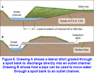 Plan a minimum number of field ditches located, where possible, at right angles to the lateral ditch and crop rows. It is essential that lateral ditches be deep enough to drain the field ditches completely enough to permit crossing by farm machinery. The minimum depth of lateral ditches is 1.0 foot. At points where lateral ditches enter the outlet channel, grade back small overfalls on a nonerosive grade (Figure 6a). If the outlet is too deep or some other problem makes it difficult to grade the overfall, install a chute, drop spillway, or pipe (Figure 6b).
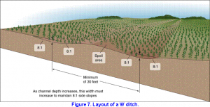
Two common types of field ditches are the single ditch and the W ditch (also called the twin or double ditch). The single ditch is used where spoil can be moved and spread in low areas of the field without obstructing flow into the ditch. The double or W ditch (illustrated in Figure 7) is used where the land drains towards the ditch from both directions, where the land is very flat and row drainage will enter from each side, and where the excavated material is not needed to fill depressions.
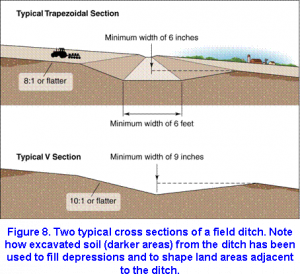
The cross section of a single ditch is usually trapezoidal or V-shaped, as shown in Figure 8. Its minimum depth should be 6 inches for trapezoidal and 9 inches for V sections, each having a minimum cross sectional area of 5 square feet. Field ditches should ordinarily not be deeper than 1 foot where they are to be crossed frequently by farm machinery. Side slopes should be 8 to 1 or flatter for a trapezoidal section and 10 to 1 for V sections.
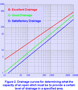 The cross section of the W ditch system is similar to that of the single ditch, except that if farm machinery is not expected to cross the ditch the side slopes toward the field should be 8 to 1 and those on the crowned section 4 to 1. The excavated earth should be shaped into a crowned section between the two ditches. The crowned section should be large enough to accommodate the spoil that has been removed. The minimum distance between ditch centers should be 30 feet. Determine the capacity of the ditches according to curve B or C in Figure 2. This figure is implemented interactively in the Ditch Sizing program. The minimum recommended design grade is 0.1 foot per 100 feet (0.1 percent). Where the channel grade is less than 0.05 foot per 100 feet, ponding and siltation may occur.
Diversions may be included in a drainage system to prevent surface runoff from sloping land from reaching a flat or depressional area. Diversion ditches are located at the base of a slope to intercept and carry surface flow to an outlet. Their side slopes range between 2 to 1 and 4 to 1, and they should be kept in sod. To minimize overtopping of the diversion, design the ditch cross section to carry the runoff from a 10-year frequency storm of 24-hour duration.
Patterns
The two main types of surface drainage patterns are random and parallel. Each includes lateral ditches that permit water to flow from the drainage system to a suitable outlet. The pattern you choose depends upon the soil type and topography of the land.
Random
The random ditch pattern is adapted to slowly permeable soils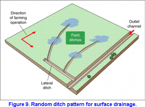 having depressional areas that are too large to be eliminated by land smoothing or grading. Field ditches connect the major low spots and remove excess surface water from them. They are generally shallow enough to permit frequent crossing by farm machinery. Soil from the ditches can be used to fill minor low spots in the field.
Field ditches should extend through most of the depressions, as shown in Figure 9, to assure complete drainage, and they should follow the natural slope of the land in accordance with Illinois drainage law.
Parallel
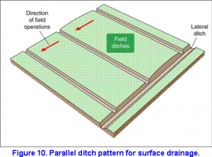 The parallel ditch pattern is suitable for flatter, poorly drained soils that have numerous shallow depressions (Figure 10). In fields that can be cultivated up and down slope, parallel field ditches are installed across the slope to break the field into shorter units of length and make it less susceptible to erosion. The field should be farmed in the direction of the greatest slope. Dead furrows are neither desirable nor necessary.
Although the ditches must be parallel, they need not be equi-distant. The spacing between them depends upon the permissible length of row drainage for the soil type and upon the amount of earth and the distance it must be moved to provide complete row drainage. The maximum length of the grade draining to a ditch should be 660 feet.
The success of a surface system using a parallel pattern depends largely upon proper spacing of the parallel ditches and the smoothing or grading between them. During the grading operation, fill all depressions and remove all barriers. Excavated material from ditches can also be used as fill for establishing grades.
Shaping the surface
Grading
Land grading (also termed precision land forming) is the reshaping of the surface of land with tractors and scrapers to planned grades. Its purpose is to provide excellent surface drainage although the amount of grading will depend upon the soil and costs. To do a good job of land grading, you need a detailed engineering survey and construction layout.
To assure adequate surface drainage, eliminate all reverse surface grades that form depressions. The recommended surface grades range from 0.1 to 0.5 percent and may be uniform or variable. The cross slopes normally should not exceed 0.5 percent. Minimum grade limits should include a construction tolerance that will permit the elimination of all depressions either in original construction or in post-construction touch up. Reverse grades can be eliminated with relative ease in a field that has minimum grades of 0.2 percent. Unusual precision in construction is required to eliminate reverse surface grades in fields that have 0.1 percent and flatter grades.
Land grading is hampered by trash and vegetation. This material should be destroyed or removed before construction and kept under control while the work is being done. The fields should be chiseled before construction if there are hard pans. The field surface should be firm when it is surveyed so that rod readings taken at stakes will reflect the true elevation. Do not grade fields when they are wet because working wet soil impairs the physical condition of the soil.
Smoothing
Land smoothing removes irregularities on the land surface and should be done after land grading and may be useful in other situations. Special equipment such as a land plane or land leveler should be used. The purpose of land smoothing is to improve surface drainage. The smoothing operation may ordinarily be directed in the field without detailed surveys or plans, although grid surveys may be needed for some critical parts of the field.
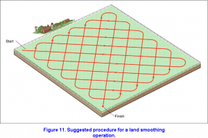
A smoothing operation consists of a minimum of three passes with a land leveler. Make the first two passes on opposite diagonals as noted in Figure 11 and the last pass in the direction of cultivation. Either before or after the final land smoothing operation, chisel fields to loosen the cut surfaces and to blend the fill material with the underlying soil. The finished surface should be free from minor depressions so that runoff will flow unobstructed to field or lateral ditches.
Maintenance
The outlet channel, lateral ditches, and field ditches should be cleaned as needed to keep them functioning properly. Small deposits of silt often greatly reduce the capacity of a surface drainage system and cause partial or complete failure of it. After each heavy rain, the outlet channel and ditches should be inspected, and silt deposits or other obstructions removed. Brushy types of vegetation, such as cattails, willows, and cottonwoods, are a menace to surface ditches and should be cut or sprayed once or twice each year as needed.
Maintenance of areas that have been graded is critical during the first year or two after construction. Settlement of the fill areas may make several annual land smoothing operations necessary. In some cases, particularly where deep fill has been made, it may be necessary to cut and fill again, using tractors and scrapers to eliminate depressions and reverse surface grades. It is suggested that after each plowing a land plane be operated over the area at least twice, making one pass along each diagonal (Figure 11). This operation will not only take care of settlement in the field areas and erase all scars to the land surface caused by field operations but also provide a good seed bed.