First Embodiment
Configuration of An Imprint apparatus
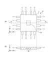
An imprint apparatus according to a first embodiment is described. Fig. 1 illustrates a configuration of an imprint apparatus 1 according to the first embodiment. The axis extending in the vertical direction is defined as the Z axis, and two axes at right angles with respect to each other in a plane perpendicular to the Z axis are defined as the X axis and the Y axis.
The imprint apparatus 1 forms a pattern of an imprint material 4 on a processing region 3a of a blank mold (object) 3 by using a master mold (mold) 2 including a pattern portion 2a where the pattern is formed. The imprint apparatus 1 causes the imprint material 4 to be cured by imparting to the imprint material 4 energy for curing while the imprint material 4 supplied to the processing region 3a is in contact with the master mold 2. According to the present embodiment, the energy for curing is an ultraviolet ray 7.
A radiating unit 5 that serves as a curing device emits the ultraviolet ray 7 while the processing region 3a is being deformed by using a heat release member 21 which will be described later. The ultraviolet ray 7 is reflected by a dichroic mirror 6, transmitted through the master mold 2 and radiated to the imprint material 4.
The master mold 2 has a rectangular outer peripheral shape. The pattern portion 2a is provided on a surface of the master mold 2 facing the blank mold 3. The pattern portion 2a has an irregular pattern such as a circuit pattern accurately formed by, for example, an electron-beam drawing device. The material of the master mold 2 can have a high transmittance for the ultraviolet ray 7. As an example, the material of the master mold 2 is quartz glass according to the present embodiment.
A chuck 8 includes an attracting device (not illustrated) so as to be able to hold an outer peripheral region of the pattern portion 2a at the chuck 8 by using a vacuum attracting force or an electrostatic force.
A drive mechanism 9 moves the master mold 2 and the chuck 8 mainly in the Z axis direction. Thus, an operation in which the master mold 2 and the imprint material 4 are brought into contact with each other (referred to as an "imprinting operation" hereafter) and an operation in which the master mold 2 and the imprint material 4 are separated from each other (referred to as a "mold releasing operation" hereafter) are performed. In order to position the master mold 2 with respect to the blank mold 3, the drive mechanism 9 may move the master mold 2 in the X-Y plane. Examples of an actuator adoptable to the drive mechanism 9 include, for example, a voice coil motor and an air cylinder.
A deforming mechanism 10 is used in the case, for example, where the shape of the pattern portion 2a could be distorted when the chuck 8 holds the master mold 2 and in the case where the shape of the processing region 3a could be distorted when a chuck (holding member) 16 holds the blank mold 3.
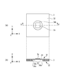
Fig. 2 illustrates a configuration of the deforming mechanism 10 that deforms the master mold 2 so as to correct the shape of the pattern portion 2a. View (a) of Fig. 2 illustrates the master mold 2 seen from the -Z side. View (b) of Fig. 2 is a sectional view illustrating the master mold 2 and the deforming mechanism 10 taken along line A-A' of Fig. 2. Actuators 11 are disposed along four sides at the outer periphery of the master mold 2. Four actuators 11 are disposed per side.
A reference state is set by reducing the size of the pattern portion 2a at a certain rate using all the actuators 11. The pattern portion 2a in the reference state is corrected to an arbitrary shape by pushing or pulling each of the actuators 11 with an arbitrary force.
Referring back to Fig. 1, an opening region 12 extends through the center of the chuck 8 and center of the drive mechanism 9 so as to avoid blocking of an optical path of the ultraviolet ray 7. A quartz glass plate 13 may be provided in the opening region 12 so that a space 14 defined by part of the opening region 12 and the master mold 2 is tightly closed.
In the case where the quartz glass plate 13 is disposed, a pressure adjustor (not illustrated) that can adjust the pressure in the space 14 is also disposed. With this configuration, for example, the pattern portion 2a is bent so as to be convex toward the blank mold 3 by increasing the pressure in the space 14 compared to the pressure outside the space 14 when the imprinting operation is performed. This can start contact between the imprint material 4 and the pattern portion 2a from a central portion of the pattern portion 2a. Thus, remaining of surrounding gas in a space between the pattern portion 2a and the imprint material 4 can be suppressed, thereby allowing all the irregularities of the pattern portion 2a to be entirely filled with the imprint material 4.
A stage 15 includes the chuck 16 and a drive mechanism 17 which, together with the chuck 16, moves the blank mold 3. The chuck 16 includes an attracting device (not illustrated) and holds the blank mold 3 such that a surface of the blank mold 3 on the opposite side (a lower surface 32 and a bottom surface 34b illustrated in Fig. 3 to be described later) to the processing region 3a side (an upper surface 31 illustrated in Fig. 3 to be described later) faces the chuck 16.
Examples of the attracting device include a device that generates a vacuum attracting force or an electrostatic force for holding the blank mold 3, a device that mechanically holds the blank mold 3, and so force. Even without any of these attracting devices, the blank mold 3 may be considered as being held by the chuck 16 as long as shifting of the position of the blank mold 3 is suppressed by a static frictional force acting between a holding surface 16a and the blank mold 3 placed on the holding surface 16a.
The drive mechanism 17 moves the blank mold 3 mainly in the X-Y plane. With this movement, the master mold 2 and the imprint material 4 on the blank mold 3 to be positioned with respect to each other. Examples of an actuator adoptable to the drive mechanism 17 include, for example, a linear motor and a planar pulse motor. During the imprinting operation and the mold releasing operation, the drive mechanism 17 may move the blank mold 3 in the Z axis direction. That is, it is sufficient that, in order to perform the imprinting operation and the mold releasing operation, at least one of the master mold 2 and the blank mold 3 be moved.
In order to highly accurately position the master mold 2 and the blank mold 3, the drive mechanism 9 and the drive mechanism 17 may include a plurality of drive systems such as a coarse drive system and a fine drive system. Furthermore, the drive mechanism 9 and the drive mechanism 17 may be able to driven in rotational directions about the X axis, rotational directions about the Y axis, and rotational directions about the Z axis.
A measurement unit 18 is, for example, a laser interferometer. The position of the stage 15 is measured by using laser light emitted from the measurement unit 18 and a mirror 19 disposed on the drive mechanism 17 so as to reflect the laser light. A controller 26 which will be described later controls the positioning of the blank mold 3 in accordance with measurement results of the measurement unit 18.
A deforming device that changes the shape of the processing region 3a includes the heat release member 21 (illustrated in Fig. 3; will be described later) and a heating mechanism 20 that heats the heat release member 21. The details of the heating mechanism 20 and the heat release member 21 will be described later.
A supply unit 22 supplies the imprint material 4 to the processing region 3a. The supply unit 22 supplies the imprint material 4 in accordance with information on the amount and disposition of the imprint material 4 determined based on, for example, the density of the pattern formed in the pattern portion 2a.
A measurement unit 23 measures relative positions of the pattern portion 2a and the processing region 3a. Light 24 emitted from the measurement unit 23 is transmitted through a dichroic mirror 25 and radiated to alignment marks (not illustrated) formed on the master mold 2 and the blank mold 3. At least four alignment marks (not illustrated) are formed on each of the master mold 2 and the blank mold 3. The measurement unit 23 receives the light 24 reflected by the alignment marks, thereby measuring the sizes of the pattern portion 2a and the processing region 3a and the deviation between the relative positions of the pattern portion 2a and the processing region 3a.
The controller 26 is connected to the heating mechanism 20, the measurement unit 23, the radiation unit 5, the drive mechanism 9, the deforming mechanism 10, and the stage 15 through wired or wireless circuits. The controller 26 includes, for example, a central processing unit (CPU) and memory (at least one of a read only memory (ROM) and a random access memory (RAM)) which are not illustrated. The memory stores software relating to an imprinting process illustrated in a flowchart of Fig. 7 which will be described later, the amounts of correction of the shapes performed by the deforming mechanism 10 and the heating mechanism 20, and so forth. The controller 26 performs centralized control over the components connected to the controller 26 in accordance with the software stored in the memory.
The controller 26 may be a combination of separate information processing devices or a single information processing device as long as the controller 26 has the functions to be performed by the controller 26.
The imprint apparatus 1 further includes a base surface plate 27, a bridge surface plate 28, and support columns 30. The stage 15 is placed on the base surface plate 27. The bridge surface plate 28 supports the drive mechanism 9. The support columns 30 vertically extend from the base surface plate 27 and support the bridge surface plate 28 through vibration isolators 29. The vibration isolators 29 suppress vibration transmitted from a floor surface to the bridge surface plate 28.
The imprint apparatus 1 includes a conveyance mechanism (not illustrated) that conveys the master mold 2 from the outside of the imprint apparatus 1 to the chuck 8, another conveyance mechanism (not illustrated) that conveys the blank mold 3 from the outside of the imprint apparatus 1 to the chuck 16, and so forth.
Fig. 3 illustrates the configuration of the blank mold 3. View (a) of Fig. 3 illustrates the blank mold 3 seen from the -Z side. View (b) of Fig. 3 is a sectional view of the blank mold 3 taken along line B-B' of view (a) of Fig. 3. The blank mold 3 has a rectangular outer peripheral having the same size as that of the master mold 2. The size of the blank mold 3 is, for example, about 150 × 150 mm.
The size of the processing region 3a is the same as the size of the pattern portion 2a. This size corresponds to, for example, a single shot region of 26 × 33 mm. The shot region is a unit region for fabricating semiconductor devices or the like. One or plurality of patterns having a chip size wished by a user are formed in a single shot region. In the case of an imprint apparatus that forms patterns in a plurality of shot regions in a single imprinting operation, the size of the processing region 3a and the pattern portion 2a may be a size corresponding to a plurality of shot regions.
The blank mold 3 includes the upper surface 31, the lower surface 32, and a recess 34. The upper surface is disposed on the processing region 3a side. The lower surface 32 is in contact with the holding surface 16a when the blank mold 3 is held by the chuck 16. The recess 34 is provided on an opposite surface side of the blank mold 3 to the upper surface 31. As illustrated in Fig. 3, the recess 34 is a recessed space that faces a side surface 34a and the bottom surface 34b that defines the bottom of the recess 34 and includes a region 33. The region 33 is disposed on the rear side of the processing region 3a on an opposite surface to the upper surface 31. The recess 34 has a circular shape in plan view when seen from the -Z side.
After a transfer pattern of the pattern portion 2a has been formed, the blank mold 3 is used as a mold on a side where the pattern is replicated in another imprint apparatus used to fabricate a semiconductor device or the like. Thus, as is the case with the master mold 2, also the material of the blank mold 3 can have a high transmittance for the ultraviolet ray 7. That is, the material of the blank mold 3 can have the substantially the same degree of absorption coefficient as the absorption coefficients of the material of the master mold 2 for light of a wavelength used to cure the master mold 2 and the imprint material 4.
According to the present embodiment, the material of the blank mold 3 is quartz glass.
Since the master mold 2 and the blank mold 3 are formed of quartz glass, the master mold 2 and the blank mold 3 have substantially the same degree of optical absorption coefficients also for light 39 used to heat the processing region 3a. The light 39 will be described later. Herein, the same degree of optical absorption coefficients means that the optical absorption coefficient of one of the master mold 2 and the blank mold 3 for the light 39 is less than four times the optical absorption coefficient of the other for the light 39.
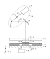
Fig. 4 illustrates a method of deforming the processing region 3a by heating. The processing region 3a is heated by using the heating mechanism 20 and the heat release member 21. The heating mechanism 20 according to the present embodiment is an optical system that radiates to the heat release member 21 light of a wavelength that transmits through the master mold 2 and the blank mold 3, thereby imparting optical energy to the heat release member 21. The heating mechanism 20 includes at least a light source 35 and a modulation element 36. According to the present embodiment, the heating mechanism 20 further includes optical elements 37 and 38.
The light source 35 emits the light 39. The light 39 is laser light of a wavelength that does not cure the imprint material 4. That is, the light 39 is different from the ultraviolet ray 7 emitted from radiation unit 5 in wavelength. Thus, for example, visible light or infrared light can be selected as the light 39.
The light 39 the inplane illuminance of which is equalized by the optical element 37 is radiated to the modulation element 36. The modulation element 36 modulates the light 39 radiated thereto to light having an arbitrary spatial radiation amount distribution (spatially distributed optical energy). As the modulation element 36, for example, a digital micromirror device (DMD) is used.
The DMD has a structure in which a plurality of micromirrors are arranged, and each of the micromirrors is inclined -12 degrees (ON state) or +12 degrees (OFF state) relative to an arrangement surface thereof so as to selectively reflect light.
The modulation element 36 converts the light 39 incident thereupon having the equalized radiation amount distribution into light having a radiation amount distribution and reflects the converted light toward the optical element 38. The modulation element 36 distributes the radiation amount in accordance with an instruction from the controller 26.
The optical element 38 adjusts the magnification so as to guide the light 39 having the radiation amount distribution to the dichroic mirror 25. The light 39 incident upon the dichroic mirror 25 is reflected in the -Z direction by the dichroic mirror 25, transmits through the master mold 2 and the blank mold 3, and is absorbed by the heat release member 21.
The heat release member 21 is provided such that, while the chuck 16 holds the blank mold 3, the heat release member 21 is disposed on the opposite surface side to the upper surface 31 and disposed in the recess 34 provided in the blank mold 3. A support table (table) 40 that supports the heat release member 21 is provided on the blank mold 3 side of the chuck 16.
The heat release member 21 and the support table 40 can be provided at positions where, in particular as illustrated in Fig. 4, the heat release member 21 and the support table 40 face the region 33 while the chuck 16 holds the blank mold 3. The support table 40 may be provided on the chuck 16 with another member interposed therebetween.
An absorption coefficient of the material of surface of the heat release member 21 on the region 33 side for the light 39 is larger than that of the material of the blank mold 3. That is, according to the present embodiment, a material having a larger absorption coefficient than that of quartz glass is used. The absorption coefficient of the material for the light 39 is preferably 50% or larger, and more preferably, 80% or larger. Examples of the material of the heat release member 21 include, for example, a silicon wafer and stainless steel.
The heat release member 21 may have a layer structure that includes two or more layers. The heat release member 21 may be provided with, for example, Inconel (registered trademark) as an absorption layer for the light 39 on the surface thereof closer to the blank mold 3. The Inconel is a super heat-resistant alloy based on carbon, chrome, or nickel. This absorption layer may be sheet shaped or coated by, for example, vapor deposition.
A layer or layers other than the absorption layer can be formed of a material or materials having a low thermal conductance or low thermal conductances such as, for example, quartz glass or low expansion glass. This can suppress escape of heat released from the heat release member 21 not toward the processing region 3a but toward the support table 40.
The heat release member 21 releases heat energy to the processing region 3a using optical energy of the light 39 received from the heating mechanism 20. The processing region 3a is heated by receiving the heat energy imparted by the heat release member 21 and deformed due to thermal expansion. In other words, the heating mechanism 20 is a deforming unit configured to deform the processing region 3a so as to change a shape of the processing region 3a.
The heat release member 21 disposed in the recess 34 while the chuck 16 holds the blank mold 3 releases the heat energy toward the processing region 3a. With the heat energy imparted by the heat release member 21, the amount of heat larger than that imparted to the pattern portion 2a can be imparted to the processing region 3a. Accordingly, independently of the absorption coefficients of the master mold 2 and the blank mold 3 for the light 39, the processing region 3a can be deformed relative to the master mold 2.
Heat energy in accordance with the radiation amount distribution in a heat releasing plane formed by the heating mechanism 20 is generated in a heat release surface (a surface on the region side on the rear side of the processing region 3a), through which heat energy is released, of the heat release member 21. Accordingly, the heat release member 21 imparts spatially distributed heat energy (uneven energy) into the surface of the processing region 3a. This causes the processing region 3a to be locally deformed, thereby allowing the shape of the processing region 3a to be corrected so that the processing region 3a has a target shape or a shape resembling the target shape.
The heat release member 21 is disposed so that the heat release member 21 is disposed in the recess 34 while the chuck 16 holds the blank mold 3. This reduces escape to the chuck 16 of the heat energy released from the heat release member 21. Thus, the heat energy obtained by the heat release member 21 can be efficiently transmitted to the processing region 3a.
A supply unit (gas supply unit) 41 supplies a gas to the recess 34 through a supply port 42 provided in the chuck 16. Desirably, the gas supplied by the supply unit 41 is inert to the light 39 and has a high thermal conductivity than air. Examples of such a gas include, for example, nitrogen or helium. Helium is most desirable. The heat released from the heat release member 21 can be efficiently transmitted to the processing region 3a by supplying the gas in a way as described above, and accordingly, the processing region 3a is easily deformed into the target shape. The chuck 16 may have an exhaust port 43 through which a displaced gas is exhausted.
The support table 40 can be formed of a material having a low thermal conductance than that of the heat release member 21. This can suppress escape of heat released from the heat release member 21 not toward the processing region 3a but toward the support table 40.
The heat release member 21 and the blank mold 3 can be not in contact with each other. This can prevent particles (not illustrated) from being attracted to the blank mold 3 when the particles are attracted to the heat release member 21. Furthermore, since the heat release member 21 and the blank mold 3 are not in contact with each other, when the height of the recess 34 slightly varies due to variation of individual blank molds 3, floating of the blank mold 3 from the chuck 16 due to the heat release member 21 can be prevented.
Also by considering heating efficiency of the processing region 3a, the distance between the heat release member 21 and the region 33 of the blank mold 3 is preferably set to 2 mm or smaller, and more preferably, set to 100 μm or smaller. This can suppress reduction of the heating efficiency of the processing region 3a due to an excessive increase in the distance between the heat release member 21 and the region of the blank mold 3, and accordingly, the heat energy released from the heat release member 21 can be efficiently transmitted to the processing region 3a.
During the imprinting operation, the supply unit 41 may supply the gas so that the pressure in the recess 34 becomes higher than the pressure outside the recess 34. This causes the processing region 3a to be bent so as to be convex toward the master mold 2. For a reason similar to the reason for bending the master mold 2, the pattern portion 2a can be entirely filled with the imprint material 4 in the imprinting operation. The processing region 3a may be bent to have a convex shape in the mold releasing operation. This can prevent the pattern of the cured imprint material 4 from being flattened during the mold releasing operation.
Example
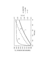
Fig. 5 illustrates an example according to the first embodiment. Fig. 5 is a result of simulation of increases in temperatures of the master mold 2 and the blank mold 3 when the processing region 3a is heated by using the heating mechanism 20 and the heat release member 21 of Fig. 4.
As the master mold 2 and the blank mold 3, quartz glass was used. The thermal conductance of the quartz was 1.38 watts per meter kelvin, the specific heat of the quartz was 740 joule per kilogram kelvin, and the coefficient of linear expansion of the quartz was 0.51. The thermal conductance between the master mold 2 and the chuck 8, the thermal conductance between the blank mold 3 and the chuck 16, the thermal conductance between the master mold 2 and air, and the thermal conductance between the blank mold 3 and air are considered.
As the heat release member 21, quartz glass coated with an absorption layer formed of carbon is coated was used. Helium was supplied to the recess 34. The distance between the heat release member 21 and the blank mold 3 was set to 50 μm. The light 39 which is visible light at a wavelength of 450 nm was radiated with a uniform radiation amount distribution of 4.3 W.
Referring to Fig. 5, time is plotted on the horizontal axis, a temperature increase is plotted on the left vertical axis, a temperature difference ΔT between the master mold 2 and the blank mold 3 is plotted on the right vertical axis. Line L1 represents the temperature increase (left vertical axis) of the master mold 2, line L2 represents the temperature increase (left vertical axis) of the blank mold 3, and line L3 represents the temperature difference ΔT°C (right vertical axis) which is obtained by subtracting the temperature of the master mold 2 from the temperature of the blank mold 3.
According to the present embodiment, with the structure in which the heating mechanism 20 and the heat release member 21 heat the processing region 3a, the blank mold 3 can be heated more than the master mold 2 by about 0.34°C. Since the coefficient of linear expansion of the master mold 2 is the same as that of the blank mold 3, the amount of deformation varies in accordance with the temperature difference ΔT. When the temperature difference ΔT is 0.34°C, the difference in deformation amount of about 0.7 nm can be obtained. Thus, with the present example, the processing region 3a can be deformed relative to the master mold 2.
<Comparative Example>
As a comparative example, the processing region 3a was heated only by using the heating mechanism 20 without the heat release member 21. In this case, when the processing region 3a was heated for 1.0 sec under the same conditions, the temperatures were increased only by about 0.03°C, and the temperature difference ΔT between the master mold 2 and the blank mold 3 was 0.01°C or lower. That is, the processing region 3a cannot be deformed relative to the master mold 2.
From the above-described example and the comparative example, the following result is obtained: the processing region 3a is deformed relative to the master mold 2 by disposing the heat release member 21 compared to the case where the heat release member 21 is not disposed.
Method of Correcting the Shapes
A method of correcting the shapes of the master mold 2 and the blank mold 3 according to the first embodiment is described with reference to Figs. 6A to 6E. Each of Figs. 6A to 6E is seen from the +Z side.
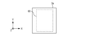
Fig. 6A illustrates the processing region 3a of the blank mold 3 not held by the chuck 16 and an ideal region 60 of the pattern to be formed. The size of the region 60 is the same as the size of the pattern portion 2a.
Fig. 6B illustrates the processing region 3a of the blank mold 3 when the blank mold 3 is not held by the chuck 16 after the pattern has been formed on the processing region 3a. At this time, the shapes of the pattern portion 2a and the processing region 3a are not corrected. A trapezoidal region 61 having a long bottom side indicates a region where the pattern of the imprint material 4 is formed.
It is illustrated that, due to, for example, a distribution of a holding force of the chuck 16, the width of the pattern formed with the imprint apparatus 1 tends to increase in the X axis direction toward a region on the -Y side. The controller 26 calculates the correction amount for the shape of the master mold 2 and the correction amount for the shape of the processing region 3a in accordance with the difference in shape between the region 60 and the region 61. A policy for calculation of these correction amounts is described with reference to Figs. 6C to 6E.
Fig. 6C illustrates the processing region 3a while the chuck 16 holds the blank mold 3. In view of the tendency in which the width of the formed pattern increases in the X axis direction toward the region on the -Y side, the controller 26 causes the master mold 2 to be deformed so as to determine the target shape of the pattern portion 2a. For example, the target shape is a trapezoidal region 62 the width in the X axis direction reduces toward the -Y side.
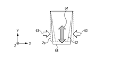
Fig. 6D illustrates a state when forces 63 are applied to the region on the -Y side of the pattern portion 2a by using the deforming mechanism 10. The shape of the pattern portion 2a becomes a trapezoid 65 as a result of extension of the pattern portion 2a in arrow 64 directions (Y axis directions) in accordance with the Poisson's ratio. In order to address this, the region 62 is temporarily heated only during the formation of the pattern so as to be deformed into a shape the same as or resembling the trapezoid 65.
Fig. 6E illustrates a state of the region 62 the inside of which is virtually divided into subregions A to D. The controller 26 causes the heating mechanism 20 and the heat release member 21 to impart heat energy to the processing region 3a. Specifically, the heat energy that is imparted is spatially distributed so that, among the subregions A to D of the processing region 3a, the temperature is highest in the subregion A and reduced in the subregion B, further reduced in the subregion C, and further reduced in the subregion D in this order. The deformation amount increases as the heat amount imparted to the subregions of the region 62 increases. During the heating, the size of the processing region 3a is the same as the size of the trapezoid 65.
In a way as described above, the imprint material 4 can be cured in a state in which the corrected shapes of the pattern portion 2a and the processing region 3a are coincident with the shape 60 which is also the shape of the pattern portion 2a. After the heating is stopped, the size of the region of the shape 60 returns to the size of the region 62. When removed from the chuck 16, the shape of the region 62 changes into the same shape as the shape of the region 60 of Fig. 6A. Thus, the pattern having an ideal shape can be formed.
Although the region 61 has a trapezoidal shape in the correcting method having been described with reference to Fig. 6B, the pattern can be formed to have a shape the same as or similar to the shape of the region 60 through appropriate correction even when the region 61 has another shape such as a rhomboidal shape, an arcuate shape, a barrel shape, a bobbin shape, or a shape that is enlarged or reduced in the vertical and horizontal directions.
Although there are four divided subregions A to D and the heat energy is spatially distributed in the example having been described, the number of divisions is not necessarily four. Furthermore, although the processing region 3a is virtually divided into the subregions A to D in the Y direction in the example having been described, the processing region 3a may be divided in the X direction or into four parts of a grating so as to impart the distributed heat energy.
Method of Imprinting
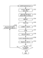
Fig. 7 is a flowchart illustrating a method of imprinting according to the first embodiment. Steps include processing steps performed by the controller 26 and steps performed by the components of the imprint apparatus 1 other than the controller 26 in accordance with instructions issued by the controller 26.
It is assumed that the controller 26 has already calculated the correction amount for the shape of the pattern portion 2a and the correction amount for the shape of the processing region 3a in advance. That is, the amount of control performed on the deforming mechanism 10 and the radiation amount distribution to be formed by the heating mechanism 20, which are required to correct the shape of the processing region 3a so that the shape of the processing region 3a is the same as or resembles the target shape, are known.
The conveyance mechanisms (not illustrated) carry the master mold 2 and the blank mold 3 into the imprint apparatus 1 in accordance with instructions issued by the controller 26 (S101). The chuck 8 holds the master mold 2 and the chuck 16 holds the blank mold 3.
The drive mechanism 17 moves the blank mold 3 to a position where the processing region 3a faces the supply unit 22, so that the uncured imprint material 4 is supplied to the processing region 3a by the supply unit 22 (S102).
The drive mechanism 17 moves the blank mold 3 to a position where the blank mold 3 faces the master mold 2 (S103).
The drive mechanism 9 moves the master mold 2 downward so as to perform the imprinting operation (S104). Through contact between the pattern portion 2a and the imprint material 4, the pattern portion 2a starts to be filled with the imprint material 4.
While the pattern portion 2a and the imprint material 4 are in contact with each other, the measurement unit 23 detects the alignment marks. The drive mechanism 17 drives the blank mold 3 in accordance with the detection result. Thus, the master mold 2 and the blank mold 3 are positioned with respect to each other (S105).
The heating mechanism 20 radiates the light 39 to the heat release member 21, and the heat release member 21 releases the heat energy toward the region 33. The processing region 3a is heated by the heat energy from the heat release member 21 and deformed (S106).
The ultraviolet ray 7 is radiated to the imprint material 4 by using the radiation unit 5 and the dichroic mirror 6 so as to cure the imprint material 4 and form a pattern in the cured imprint material 4 (S107). The curing step is performed while the processing region 3a is deformed by using the heat release member 21. When the deforming mechanism 10 is used as in the present embodiment, in addition to the above description, the imprint material 4 is cured while the pattern portion 2a is deformed by the deforming mechanism 10.
The drive mechanism 9 moves the master mold 2 upward so as to perform the mold releasing operation (S108). Through the above-described steps, the pattern is formed in the cured imprint material 4 on the processing region 3a. This pattern is a transferred pattern of a pattern formed in the pattern portion 2a.
After the master mold 2 and the imprint material 4 have been separated from each other, the conveyance mechanism carries out the blank mold 3 from the imprint apparatus 1 (S109).
After the blank mold 3 has been carried out, the shape of the formed pattern with respect to the shape of the processing region 3a is measured with a measurement device (not illustrated; S110). The controller 26 determines whether or not the measurement result in S110 falls within an allowable range (S111). When the controller 26 determines that the measurement result falls within the allowable range, processing illustrated in this flowchart ends. The pattern is formed in other blank molds 3 in the same or similar way using the correction amounts having been calculated in advance before S101.
When the controller 26 determines in S111 that the measurement result does not fall within the allowable range, the correction amount for the shape of the master mold 2 and the correction amount for the shape of the blank mold 3 are calculated again (S112). Steps of S101 to S111 are repeatedly performed until the difference between the ideal shape and the formed shape falls within the allowable range. Thus, an optimum correction amount for the shape of the pattern portion 2a and an optimum correction amount for the shape of the processing region 3a for contact between the pattern portion 2a and the processing region 3a can be calculated. The pattern of the imprint material 4 can be formed on the processing region 3a with higher accuracy by using the correction amounts of the shapes having been obtained as above.
The method of imprinting by which the pattern is formed in the blank mold 3 has been described. Steps S104 to S106 can be reversed. Also, these steps may be performed in parallel.
Furthermore, the line width and the like of the formed pattern may be measured in S110 so as to, in parallel with S112, generate again data indicating a position where the imprint material 4 for use in the step of supplying the imprint material 4.
Furthermore, when the correction amount for the shape of the pattern portion 2a and the correction amount for the shape of the processing region 3a are unknown at the stage of S101, steps S101 to S112 are performed on the processing region 3a with the performance of step S105 omitted. In this way, the controller 26 can calculate the correction amount for the shape of the pattern portion 2a and the correction amount for the shape of the processing region 3a.
Second Embodiment
An imprint apparatus according to a second embodiment has the heat release member 21 having a different configuration from that of the imprint apparatus 1. Other elements are the same as or similar to those of the imprint apparatus 1 and description thereof is omitted.
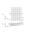
Fig. 8 illustrates the configuration of the heat release member 21 according to the second embodiment. View (a) of Fig. 8 illustrates the heat release member 21 seen from the +Z side. View (b) of Fig. 8 is a sectional view of the heat release member 21 taken along line C-C' of view (a) of Fig. 8.
The heat release surface of the heat release member 21 has grooves 47 that divide the heat release surface into a plurality of regions 46. According to the present embodiment, the grooves 47 are equally spaced in the X axis direction and the Y axis direction so that the heat release surface is divided into 4 × 7 regions 46.
According to the present embodiment, as is the case with the first embodiment, the heat release member 21 disposed in the recess 34 while the chuck 16 holds the blank mold 3 releases the heat energy toward the processing region 3a. With the heat energy imparted by the heat release member 21, the amount of heat larger than that imparted to the pattern portion 2a can be imparted to the processing region 3a. Furthermore, independently of the absorption coefficients of the master mold 2 and the blank mold 3 for the light 39, the processing region 3a can be deformed relative to the master mold 2.
The heat release member 21 is disposed so as to be disposed in the recess 34 while the chuck 16 holds the blank mold 3. This reduces escape to the chuck 16 of the heat energy released from the heat release member 21. Thus, the heat energy obtained by the heat release member 21 can be efficiently transmitted to the processing region 3a.
The gas in the recess 34 exists in spaces between the adjacent regions 46. This can suppress dispersion of the heat energy produced by converting the optical energy received from the heating mechanism 20 inside the heat release member 21. That is, equalization of the temperature at the surface of the heat release member 21 facing the blank mold 3 can be suppressed.
Thus, the heat release member 21 can easily release the heat energy distributed so as to correspond to the radiation amount distribution of the light 39. Accordingly, the processing region 3a is locally deformed more easily than with the first embodiment, thereby allowing the shape of the processing region 3a to be easily formed to have the target shape or a shape resembling the target shape.
Regarding the depth of the grooves 47, the thickness of the heat release member 21 is preferably 0.05 mm or larger. This can efficiently suppress dispersion of the heat between the adjacent regions 46. The grooves 47 may be formed in a direction other than the X axis direction or the Y axis direction.
Furthermore, the number of the divided regions 46 is not limited to that of the present embodiment. At least four regions 46 can be provided. The surface facing the blank mold 3 may be divided into 9 × 11 so as to set each of the regions 46 has the size of about 3 mm square. The grooves 47 are not necessarily equally spaced. For example, the distance between the grooves 47 may vary between a region near the center of the heat release member 21 and a region near the outer periphery of the heat release member 21.
In order to provide the grooves 47, the material of the heat release member 21 can have a low thermal conductance and can be easily processed for forming the grooves 47. For example, out of the materials having been described, stainless steel is particularly desirable.
Since the method of imprinting performed on the blank mold 3 is the same as or similar to that of the first embodiment, description thereof is omitted.
Third Embodiment
An imprint apparatus according to a third embodiment has a different configuration for heating the heat release member 21 from that of the imprint apparatus 1. A deforming device that changes the shape of the processing region 3a includes the heat release member 21 and a heating mechanism 48 which is used instead of the heating mechanism 20. The heat release member 21 has the grooves 47 according to the second embodiment. Other elements are the same as or similar to those of the imprint apparatus 1 and description thereof is omitted.
View (a) of Fig. 9 illustrates the heat release member 21 seen from the +Z side. View (b) of Fig. 9 is a sectional view of the heat release member 21 taken along line D-D' of view (a) of Fig. 9. The heating mechanism 48 includes a plurality of heaters 49 that serve as devices imparting heat energy to the heat release member 21 and a control unit 50 that controls the heat amount to be generated by the heaters 49 in accordance with instructions from the controller 26.
The heaters 49 are disposed below the heat release member 21. Positions where the heaters 49 are disposed may correspond one-to-one with the regions 46. The number of the heaters 49 and the number of the regions 46 are not limited to the above description.
The heat release member 21 releases the heat energy toward the region 33 by using the heat energy received from the plurality of heaters 49.
According to the present embodiment, as is the case with the first embodiment, the heat release member 21 disposed in the recess 34 while the chuck 16 holds the blank mold 3 releases the heat energy toward the processing region 3a. With the heat energy imparted by the heat release member 21, the amount of heat larger than that imparted to the pattern portion 2a can be imparted to the processing region 3a. Accordingly, independently of the absorption coefficients of the master mold 2 and the blank mold 3 for the light 39, the processing region 3a can be deformed relative to the master mold 2.
The heating mechanism 48 may impart spatially distributed heat energy. In this case, the heat release member 21 releases the heat energy toward the region 33 while maintaining the spatial distribution of the heat energy received from the plurality of heaters 49. Since the heat release member 21 imparts the spatially distributed heat energy into the surface of the processing region 3a, the processing region 3a can be locally deformed. This allows the shape of the processing region 3a to be corrected so that the processing region 3a has the target shape.
The heat release member 21 is disposed so as to be disposed in the recess 34 while the chuck 16 holds the blank mold 3. This reduces escape to the chuck 16 of the heat energy released from the heat release member 21. Thus, the heat energy obtained by the heat release member 21 can be efficiently transmitted to the processing region 3a.
The depth of the grooves 47 can be 80% or larger of the thickness of the heat release member 21. This can suppress (reduce) dispersion of the heat in the heat release member 21 while the heat from the heaters 49 is moving to the surface facing the blank mold 3.
As a variant to the present embodiment, the heat release member 21 may be a heater that itself can generate and impart distributed heat energy. In this case, the heating mechanism 20 or the heating mechanism 48 is not required.
Since the method of imprinting performed on the blank mold 3 is the same as or similar to that of the first embodiment, description thereof is omitted.
Fourth Embodiment
According to a fourth embodiment, a recess 51 as illustrated in Fig. 10 is formed on a processing region 52a side of the chuck 16. The recess 51 is a recessed space facing a side surface 51a, a bottom surface 51b, and a region 53. That is, while the chuck 16 holds a blank mold 52, the recess 51 is disposed on the opposite surface side to the upper surface 31. The heat release member 21 and the support table 40 are provided so as to be disposed in the recess 51 while the chuck 16 holds the blank mold 52. The heating mechanism 20, 48 and the configurations of the heat release member 21 according to any of the above-described embodiments may be applied.
According to the present embodiment, as is the case with the first embodiment, the heat release member 21 disposed in the recess 51 while the chuck 16 holds the blank mold 52 releases the heat energy toward the region 53 on the rear side of the processing region 52a on the opposite surface to the upper surface 31. With the heat energy imparted by the heat release member 21, the amount of heat larger than that imparted to the pattern portion 2a can be imparted to the processing region 52a. Accordingly, independently of the absorption coefficients of the master mold 2 and the blank mold 52 for light, the processing region 52a can be deformed relative to the master mold 2.
The heat release member 21 can impart the spatially distributed heat energy into the surface of the processing region 52a. Accordingly, the processing region 52a can be locally deformed. This allows the shape of the processing region 52a to be corrected so that the processing region 52a has the target shape.
Transmission to the chuck 16 of the heat energy released from the heat release member 21 is reduced by disposing the heat release member 21 in the recess 51. Thus, the processing region 52a can be efficiently heated.
Since the recess 51 is formed in the chuck 16, the pattern can be formed on the processing region 52a of the blank mold 52 that has no recess.
The blank mold 52 can be used, for example, for the purpose as follows: for forming a pattern in the blank mold 52 that has the recess 51 by using the blank mold 52 after the pattern is formed in the blank mold 52 by using the master mold 2. This can reduce the number of times of use of the master mold 2 in which the pattern is formed by using an electron-beam drawing device and which is expensive.
Since the method of imprinting performed on the blank mold 52 is the same as or similar to that of the first embodiment, description thereof is omitted.
Other Embodiments
The configurations of the imprint apparatuses according to the first to fourth embodiments may be appropriately combined.
The heating mechanism 20 does not necessarily radiate the light 39 to the heat release member 21 so that the light 39 transmits through the master mold 2 and the blank mold 3. For example, the heating mechanism 20 is disposed at a position where the recess 34, 51 is disposed while the chuck 16 holds the blank mold 3 so as to impart light energy directly to the heat release member 21.
Recesses may be provided in both the blank mold 3 and the chuck 16. In this case, it is sufficient that the heat release member 21 be disposed on the opposite surface side to the upper surface 31 and in one of the recesses provided in the blank mold 3 or the chuck 16 while the chuck 16 holds the blank mold 3.
Furthermore, when the deformation of the pattern portion 2a by using the deforming mechanism 10 is not required, it is sufficient that only the processing region 3a be deformed.
The coincidence of the shape of the pattern portion 2a having been corrected by the deforming mechanism 10 with the shape of the processing region 3a, 52a having been corrected by the heating mechanism 20, 48 is not necessarily targeted. The techniques described herein may be applied to the case where, for example, a user wishes to transfer to the processing region 3a a pattern the outer periphery of which has a different shape from a rectangle.
The case where the user wishes to transfer a pattern the outer periphery of which has a different shape from a rectangle is the following case. That is, the blank mold 3 in which the pattern has been formed by the above-described method of imprinting is used as the master mold to fabricate a semiconductor device or the like with another imprint apparatus.
In many cases, the shape of a shot region having already been formed in a substrate (not illustrated) such as a silicon wafer has undergone high-order distortion, thereby having a barrel shape, an arcuate shape, or the like. In such cases, when the external shape of the pattern formed in the blank mold 3 is distorted in advance, the pattern formed on the substrate by using the blank mold 3 can be highly accurately superposed on the shot region being a base pattern of the substrate.
Any of the imprint apparatuses according to the first to fourth embodiments may form a pattern on an object other than the blank mold 3, 52. The object may be, for example, quartz glass or an optical member formed of a material such as another type of glass.
A curable composition (also referred to as "uncured resin") that is cured when receiving curing energy is used as the imprint material 4. Examples of the curing energy include electromagnetic waves, heat, and so forth. The electromagnetic waves are, for example, light such as an infrared ray, a visible ray, or an ultraviolet ray selected from rays at a wavelength range from 10 nm to 1 mm.
Examples of the curable composition include a composition cured by radiating light and a composition cured by applying heat. Out of these, a photo-curable composition, which is cured by light, at least contains a polymerizable compound and a photopolymerization initiator. The photo-curable composition may contain a non-polymerizable compound or a solvent according to need. The non-polymerizable compound is, for example, at least one type selected from the group consisting of a sensitizer, a hydrogen donator, an internal mold release agent, a surfactant, an antioxidant, and a polymer component.
The imprint material 4 is applied on the substrate in the form of a film by using a spin coater or a slit coater. Alternatively, the imprint material 4 may be applied on the substrate, by using a liquid ejecting head, in the form of droplets or in the form of a film or an island formed of a plurality of droplets continuous with one another. The viscosity of the imprint material 4 (viscosity at 25°C) is, for example, from 1 to 100 millipascal seconds.
Although an example of the material of the master mold 2 is quartz glass in the above description, the material of the master mold 2 may be another material. Examples of the other material include glass such as silicate glass, calcium fluoride, magnesium fluoride, and acrylic glass, and other materials such as sapphire, gallium nitride, polycarbonate, polystyrene, acrylic, and polypropylene. These materials may be arbitrarily layered to form the master mold 2.
Method of Fabricating Products
The pattern of the cured material formed on the substrate with any of the imprint apparatuses according to the above-described embodiments is permanently used at at least part of any of a variety of products or temporally used for fabricating a variety of products.
The substrate is formed of, for example, glass, ceramic, metal, a semiconductor, or resin. A member formed of a different material from that of the substrate may be formed on the surface of the substrate according to need. Specifically, the substrate is a silicon wafer, a compound-semiconductor wafer, a quartz glass wafer, or the like.
Examples of the products include electric circuit elements, optical elements, micro-electromechanical systems (MEMSs), recording elements, sensors, molds, and so forth. Examples of the electric circuit elements include, for example, a volatile or involatile semiconductor memories such as dynamic random access memories (DRAMs), static random access memories (SRAMs), flash memories, and magnetoresistive random access memories (MRAMs) and semiconductor devices such as large scale integrated circuits (LSIs), charge coupled devices (CCDs), image sensors, and field-programmable gate arrays (FPGAs). Examples of the molds include, for example, molds for imprinting (master molds).
The pattern of the cured material is at least used as it is as at least one of components of any of the above-described products or temporarily used as a resist mask. The resist mask is removed after a process such as etching or ion implantation has been performed during processing of the substrate. The processing of the substrate may further include other known processing steps (such as developing, oxidation, deposition, vapor deposition, planarization, resist removal, dicing, bonding, and packaging).
While the present invention has been described with reference to exemplary embodiments, it is to be understood that the invention is not limited to the disclosed exemplary embodiments. The scope of the following claims is to be accorded the broadest interpretation so as to encompass all such modifications and equivalent structures and functions.
This application claims the benefit of Japanese Patent Application No. 2015-254740, filed December 25, 2015, which is hereby incorporated by reference herein in its entirety.