WO2016194868A1 - Medical manipulator - Google Patents
Medical manipulator Download PDFInfo
- Publication number
- WO2016194868A1 WO2016194868A1 PCT/JP2016/065885 JP2016065885W WO2016194868A1 WO 2016194868 A1 WO2016194868 A1 WO 2016194868A1 JP 2016065885 W JP2016065885 W JP 2016065885W WO 2016194868 A1 WO2016194868 A1 WO 2016194868A1
- Authority
- WO
- WIPO (PCT)
- Prior art keywords
- base end
- motor unit
- treatment instrument
- engaged
- medical manipulator
- Prior art date
Links
Images


Classifications
-
- A—HUMAN NECESSITIES
- A61—MEDICAL OR VETERINARY SCIENCE; HYGIENE
- A61B—DIAGNOSIS; SURGERY; IDENTIFICATION
- A61B34/00—Computer-aided surgery; Manipulators or robots specially adapted for use in surgery
- A61B34/30—Surgical robots
- A61B34/35—Surgical robots for telesurgery
-
- A—HUMAN NECESSITIES
- A61—MEDICAL OR VETERINARY SCIENCE; HYGIENE
- A61B—DIAGNOSIS; SURGERY; IDENTIFICATION
- A61B34/00—Computer-aided surgery; Manipulators or robots specially adapted for use in surgery
- A61B34/30—Surgical robots
- A61B34/37—Master-slave robots
-
- A—HUMAN NECESSITIES
- A61—MEDICAL OR VETERINARY SCIENCE; HYGIENE
- A61B—DIAGNOSIS; SURGERY; IDENTIFICATION
- A61B34/00—Computer-aided surgery; Manipulators or robots specially adapted for use in surgery
- A61B34/70—Manipulators specially adapted for use in surgery
- A61B34/71—Manipulators operated by drive cable mechanisms
-
- A—HUMAN NECESSITIES
- A61—MEDICAL OR VETERINARY SCIENCE; HYGIENE
- A61B—DIAGNOSIS; SURGERY; IDENTIFICATION
- A61B34/00—Computer-aided surgery; Manipulators or robots specially adapted for use in surgery
- A61B34/70—Manipulators specially adapted for use in surgery
- A61B34/77—Manipulators with motion or force scaling
-
- B—PERFORMING OPERATIONS; TRANSPORTING
- B25—HAND TOOLS; PORTABLE POWER-DRIVEN TOOLS; MANIPULATORS
- B25J—MANIPULATORS; CHAMBERS PROVIDED WITH MANIPULATION DEVICES
- B25J3/00—Manipulators of master-slave type, i.e. both controlling unit and controlled unit perform corresponding spatial movements
-
- B—PERFORMING OPERATIONS; TRANSPORTING
- B25—HAND TOOLS; PORTABLE POWER-DRIVEN TOOLS; MANIPULATORS
- B25J—MANIPULATORS; CHAMBERS PROVIDED WITH MANIPULATION DEVICES
- B25J9/00—Programme-controlled manipulators
- B25J9/16—Programme controls
- B25J9/1679—Programme controls characterised by the tasks executed
- B25J9/1689—Teleoperation
-
- A—HUMAN NECESSITIES
- A61—MEDICAL OR VETERINARY SCIENCE; HYGIENE
- A61B—DIAGNOSIS; SURGERY; IDENTIFICATION
- A61B17/00—Surgical instruments, devices or methods, e.g. tourniquets
- A61B2017/00477—Coupling
-
- A—HUMAN NECESSITIES
- A61—MEDICAL OR VETERINARY SCIENCE; HYGIENE
- A61B—DIAGNOSIS; SURGERY; IDENTIFICATION
- A61B34/00—Computer-aided surgery; Manipulators or robots specially adapted for use in surgery
- A61B34/30—Surgical robots
- A61B2034/301—Surgical robots for introducing or steering flexible instruments inserted into the body, e.g. catheters or endoscopes
-
- A—HUMAN NECESSITIES
- A61—MEDICAL OR VETERINARY SCIENCE; HYGIENE
- A61B—DIAGNOSIS; SURGERY; IDENTIFICATION
- A61B90/00—Instruments, implements or accessories specially adapted for surgery or diagnosis and not covered by any of the groups A61B1/00 - A61B50/00, e.g. for luxation treatment or for protecting wound edges
- A61B90/06—Measuring instruments not otherwise provided for
- A61B2090/064—Measuring instruments not otherwise provided for for measuring force, pressure or mechanical tension
- A61B2090/065—Measuring instruments not otherwise provided for for measuring force, pressure or mechanical tension for measuring contact or contact pressure
-
- A—HUMAN NECESSITIES
- A61—MEDICAL OR VETERINARY SCIENCE; HYGIENE
- A61B—DIAGNOSIS; SURGERY; IDENTIFICATION
- A61B90/00—Instruments, implements or accessories specially adapted for surgery or diagnosis and not covered by any of the groups A61B1/00 - A61B50/00, e.g. for luxation treatment or for protecting wound edges
- A61B90/06—Measuring instruments not otherwise provided for
- A61B2090/064—Measuring instruments not otherwise provided for for measuring force, pressure or mechanical tension
- A61B2090/066—Measuring instruments not otherwise provided for for measuring force, pressure or mechanical tension for measuring torque
-
- A—HUMAN NECESSITIES
- A61—MEDICAL OR VETERINARY SCIENCE; HYGIENE
- A61B—DIAGNOSIS; SURGERY; IDENTIFICATION
- A61B90/00—Instruments, implements or accessories specially adapted for surgery or diagnosis and not covered by any of the groups A61B1/00 - A61B50/00, e.g. for luxation treatment or for protecting wound edges
- A61B90/08—Accessories or related features not otherwise provided for
- A61B2090/0807—Indication means
- A61B2090/0811—Indication means for the position of a particular part of an instrument with respect to the rest of the instrument, e.g. position of the anvil of a stapling instrument
-
- A—HUMAN NECESSITIES
- A61—MEDICAL OR VETERINARY SCIENCE; HYGIENE
- A61B—DIAGNOSIS; SURGERY; IDENTIFICATION
- A61B90/00—Instruments, implements or accessories specially adapted for surgery or diagnosis and not covered by any of the groups A61B1/00 - A61B50/00, e.g. for luxation treatment or for protecting wound edges
- A61B90/90—Identification means for patients or instruments, e.g. tags
-
- Y—GENERAL TAGGING OF NEW TECHNOLOGICAL DEVELOPMENTS; GENERAL TAGGING OF CROSS-SECTIONAL TECHNOLOGIES SPANNING OVER SEVERAL SECTIONS OF THE IPC; TECHNICAL SUBJECTS COVERED BY FORMER USPC CROSS-REFERENCE ART COLLECTIONS [XRACs] AND DIGESTS
- Y10—TECHNICAL SUBJECTS COVERED BY FORMER USPC
- Y10S—TECHNICAL SUBJECTS COVERED BY FORMER USPC CROSS-REFERENCE ART COLLECTIONS [XRACs] AND DIGESTS
- Y10S901/00—Robots
- Y10S901/30—End effector
- Y10S901/41—Tool
Definitions
- the present invention relates to a medical manipulator.
- This application claims priority based on Japanese Patent Application No. 2015-111329 filed in Japan on June 1, 2015, the contents of which are incorporated herein by reference.
- a clean area that directly touches the patient's body and an unclean area that does not touch the patient are set.
- Devices that belong to the area can be attached and detached.
- the power transmission path for operating the end effector disposed in the clean area can be separated between the clean area and the dirty area.
- the clean area equipment and the unclean area so that power can be transmitted between the clean area where the end effector is disposed and the unclean area where the operation unit is disposed.
- the end effector and the operation unit may move unintentionally. For example, if the end effector may move unintentionally in the body, careful operation is required so that the end effector does not contact the body tissue.
- the present invention has been made in view of the above-described circumstances, and an object thereof is to make it difficult for an end effector to perform an unintended operation in the process of attaching and detaching a medical manipulator between a clean area and an unclean area.
- a medical manipulator includes an end effector, a long portion connected to the proximal end side of the end effector, and a first base connected to the proximal end side of the long portion.
- An end portion a first transmission portion that is provided at the first base end portion and transmits power for operating the elongated portion or the end effector from the first base end portion, and the first A second base end portion attachable to and detachable from the base end portion; a drive portion provided at the second base end portion for generating power for operating the end effector and the elongated portion; and the second Provided at the base end portion of the second transmission portion for transmitting the power generated by the drive portion to the first transmission portion, and provided at the first transmission portion, wherein the first base end portion is the second transmission portion.
- An engaged portion that is pushed by the protrusion and can be rotated so as to have a predetermined positional relationship based on the shape of the protrusion in the engagement process with the protrusion, and a command to the drive portion A control unit for giving, and an operation unit for giving a command to the control unit.
- the engaged portion may have a tapered surface that can come into contact with the protruding portion.
- control unit is configured to attach the first base end and the second base end in the mounting process of the first base end and the second base end.
- a command may be given to the driving unit so that the engaging unit has the predetermined positional relationship.
- control unit is configured such that the protrusion and the engaged portion are engaged with each other in the predetermined positional relationship.
- the operation unit may be initialized when the protrusion and the engaged portion are engaged with each other in the predetermined positional relationship.
- FIG. 1 is an overall view showing a medical manipulator according to a first embodiment of the present invention. It is a perspective view showing a part of medical manipulator concerning a 1st embodiment of the present invention. It is a block diagram of the medical manipulator concerning a 1st embodiment of the present invention. It is a perspective view showing a part of medical manipulator concerning a 1st embodiment of the present invention. It is a schematic diagram which shows the treatment tool of the medical manipulator which concerns on 1st Embodiment of this invention. It is a schematic diagram which shows the motor unit of the medical manipulator which concerns on 1st Embodiment of this invention. It is a conceptual diagram of the internal structure of the motor unit of the medical manipulator which concerns on 1st Embodiment of this invention.
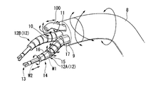
- FIG. 1 is an overall view showing a medical manipulator according to this embodiment.
- FIG. 2 is a perspective view showing a part of the medical manipulator.
- FIG. 3 is a block diagram of the medical manipulator.
- FIG. 4 is a perspective view showing a part of the medical manipulator.
- FIG. 5 is a schematic diagram showing a treatment instrument of a medical manipulator.
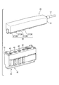
- FIG. 6 is a schematic diagram showing a motor unit of a medical manipulator.
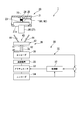
- FIG. 7 is a conceptual diagram of the internal structure of the motor unit.
- FIG. 8 is a perspective view showing a protrusion provided on the first transmission portion of the treatment instrument.
- FIG. 9 is a plan view showing a protrusion provided on the first transmission portion of the treatment instrument.
- FIG. 10 is a perspective view showing the engaged portion provided in the second transmission portion of the motor unit.
- FIG. 11 is a plan view showing the engaged portion provided in the second transmission portion of the motor unit.
- the medical manipulator 1 includes a master manipulator 2, a slave manipulator 7, and a controller 50 (control unit).
- the master manipulator 2 has a master arm 3 and a display unit 6.
- the master arm 3 is provided for operating medical devices such as a treatment instrument 12 and an endoscope 100 described later from outside the body.
- the master arm 3 of the present embodiment functions as an operation unit that gives a command for operating the treatment instrument 12.
- the master arm 3 is connected to a master control unit 51 (described later) provided in the controller 50.
- the master arm 3 has a grip part 4 and an articulated arm 5.
- the grip part 4 is provided at the end of the master arm 3 so that the operator can hold it to operate the master arm 3.
- the multi-joint arm 5 has at least one degree of freedom by having a plurality of joints.
- the multi-joint arm 5 has a plurality of encoders (not shown) for detecting the position and posture of the grip portion 4.
- the operation in which the operator holds the grip portion 4 of the master arm 3 and moves the articulated arm 5 is converted into information necessary for operating the treatment instrument 12, the endoscope 100, and the like by each encoder.
- the arrangement of the plurality of joints of the multi-joint arm 5 may be the same as that of the treatment instrument 12, that is, a similar relationship. In that case, since the operation of moving each joint of the multi-joint arm 5 is reflected in the operation of the treatment instrument 12, the operator can perform an intuitive operation.
- the display unit 6 is provided to display an image captured by an endoscope 100 described later, information necessary for operating the medical manipulator 1 according to the present embodiment, and the like.
- the display unit 6 is connected to the controller 50.
- the display unit 6 displays an image based on a video signal output from the controller 50, for example.
- the configuration of the display unit 6 is not particularly limited.
- the slave manipulator 7 includes a medical overtube 8, a treatment instrument 12, a motor unit 30, and a slave arm 49.
- the medical overtube 8 has a first lumen 9 and a second lumen 10 for attaching the treatment instrument 12, and a third lumen 11 for attaching the endoscope 100. is doing.
- the medical overtube 8 may be a cylindrical shape that can be inserted into a digestive tract or the like through a natural opening such as a patient's mouth. If necessary, the medical overtube 8 may be capable of bending in response to an operation outside the body.
- the medical overtube 8 is not limited to the above configuration.
- the medical overtube 8 may have a configuration in which the treatment tool 12 is fixed to the medical overtube 8 in a state where the treatment tool 12 protrudes from the distal end of the medical overtube 8.
- the treatment tool 12 is a manipulator for treating a treatment target site in the body according to an operation from outside the body.
- the treatment instrument 12 can be inserted through the first lumen 9 or the second lumen 10 of the medical overtube 8.
- the treatment instrument 12 includes a first treatment instrument 12A that can be inserted into the first lumen 9 and a second treatment instrument 12B that can be inserted into the second lumen 10.
- the medical manipulator 1 according to the present embodiment is not limited to having two treatment tools 12, and may have only one treatment tool 12 or three treatment tools 12. You may have more.
- the first treatment tool 12A and the second treatment tool 12B have a configuration for performing treatment such as incision, gripping, and suturing on a treatment target site in the body.
- the configuration of the first treatment instrument 12A and the configuration of the second treatment instrument 12B may be the same as each other or different from each other. Below, it demonstrates regarding the structure of 12 A of 1st treatment tools of the two treatment tools 12, and the description regarding the 2nd treatment tool 12B is abbreviate
- the first treatment instrument 12 ⁇ / b> A (hereinafter simply referred to as “treatment instrument 12”) has an end effector 13, a long part 14, and a first base end part 20.
- the end effector 13 is provided at the distal end of the treatment tool 12 in order to treat a treatment target site in the body.
- the configuration of the end effector 13 is not particularly limited as long as it is a treatment unit having an action on the treatment target site.
- the end effector 13 may be one that performs a surgical procedure on tissue inside the body such as grasping forceps, an incision knife, or an electrode, and is an optical or ultrasonic observation device for observing the inside of the body. May be.
- the end effector 13 may be a grasping forceps having a pair of jaws that can be opened and closed in accordance with a pulling operation by the drive wire W2, or a knife that cuts a tissue when a high-frequency current is applied.
- the long portion 14 is a long flexible member that is inserted into the body in order to guide the end effector 13 to a treatment target site in the body.
- the long portion 14 has flexibility as a whole.
- the flexible long portion 14 can guide the end effector 13 from the natural opening such as the mouth to the treatment target site along the digestive tract or the like through the digestive tract or the like.
- the long portion 14 may be flexible, or may be a rigid member that is substantially linear. Below, an example of a structure of the elongate part 14 which has flexibility is shown.
- the long portion 14 having flexibility has a joint portion 15 and a flexible tube portion 17.
- the joint portion 15 has a plurality of joint elements 16 arranged in the center line direction of the long portion 14 and connected to each other, and can be bent and deformed as a whole.
- An angle wire W ⁇ b> 1 is connected to the joint element 16 at the most distal end side in the joint portion 15 for transmitting a force for bending and deforming the joint portion 15 from the first base end portion 20 side.
- the flexible tube portion 17 is a tube having flexibility to the extent that it can have a curved shape that follows the curved shape of the first lumen 9 or the second lumen 10 when the medical overtube 8 is in a curved state. It is a shaped member.
- An angle wire W1 for bending and deforming the joint portion 15 and a drive wire W2 for operating the end effector 13 are inserted through the flexible tube portion 17.
- the first base end portion 20 includes a first housing 21 and a first transmission portion 22.
- the first housing 21 is fixed to the proximal end of the flexible tube portion 17.
- the interior of the first housing 21 is in communication with the interior of the flexible tube portion 17.
- Proximal ends of the above-described drive wire W2 and angle wire W1 disposed inside the flexible tube portion 17 are disposed in the first housing 21.
- the first housing 21 has an opening 21a (see FIG. 7) that can expose a protrusion 26 to be described later.
- the first transmission unit 22 includes a first rotating body 23 and a protrusion 26.
- the first rotating body 23 is a rod-like member around which the proximal end portion of the angle wire W1 or the proximal end portion of the drive wire W2 is wound.
- a number of first rotating bodies 23 corresponding to the number of drive wires W2 and angle wires W1 are provided in the first housing 21.
- the first rotating body 23 is connected to the first casing 21 so as to be rotatable about a predetermined rotation center X1. Further, the first rotating body 23 resists the traction force transmitted from the angle wire W1, the drive wire W2, etc. in a state where the first base end portion 20 is detached from a motor unit 30 (second base end portion) described later. Thus, it has a rotational resistance that does not rotate in the first housing 21.
- the first rotating body 23 may be slidable with respect to the first casing 21 with a frictional force having a predetermined magnitude with respect to the first casing 21 as the rotational resistance.
- the center line of the first rotating body 23 is a predetermined rotation center X1 in the first rotating body 23.
- the first end 24 is in the first casing so that the first end 24 of both ends 24, 25 in the center line direction of the first rotating body 23 can rotate with respect to the first casing 21. 21 is connected.
- the protrusion 26 is exposed to the outside of the first housing 21 through the opening 21 a of the first housing 21.
- the protrusion part 26 may protrude from the opening part 21a, if the to-be-engaged part 42 mentioned later can engage with the protrusion part 26 through the opening part 21a of the 1st housing
- the protrusion 26 can rotate integrally with the first rotating body 23 around a predetermined rotation center X1 (in the present embodiment, the center line of the first rotating body 23) in the first rotating body 23.
- the protrusion 26 and the first rotating body 23 are integrally molded.
- the protrusion part 26 and the 1st rotary body 23 are separate bodies, and may mutually be connected.
- the protrusion 26 in the present embodiment has an engaging strip 27 that is long in a direction orthogonal to the predetermined rotation center X1 in the first rotating body 23.
- the engaging strip portion 27 has a shape based on the shape of the engaged portion 42 so as to engage with the engaged portion 42 when in a predetermined positional relationship with the engaged portion 42 described later. is doing.
- the motor unit 30 can be attached to and detached from the proximal end of the treatment instrument 12 as a second proximal end that can be attached to and detached from the first proximal end 20. It is.
- the motor unit 30 includes a second housing 31, a drive unit 32, a second transmission unit 38, and a treatment instrument mounting sensor 45.
- the second casing 31 has a container shape in which the second transmission unit 38 and the driving unit 32 are accommodated.
- the second housing 31 is detachable from the first housing 21 by, for example, manual work.
- the driving unit 32 includes an actuator 33, a first encoder 34, a speed reduction mechanism 35, a second encoder 36, and a controller 37.
- the actuator 33 operates in accordance with a command given to the drive unit 32 by a slave control unit 52 described later and a command from the controller 37.
- the actuator 33 generates power for operating the end effector 13 and the long portion 14.
- the power generated by the actuator 33 is transmitted to the second transmission unit 38.
- the first encoder 34 is connected to the controller 37 and the slave controller 52 in order to detect the rotation amount of the actuator 33.
- the deceleration mechanism 35 has, for example, a plurality of gears, and is connected to the actuator 33 and the second transmission unit 38 in order to decelerate and transmit the power generated by the actuator 33 to the second transmission unit 38.
- the second encoder 36 is attached to the second rotating body 39 in order to detect the amount of rotation of the second rotating body 39 described later of the second transmission portion 38.
- the controller 37 is connected to the first encoder 34 and the second encoder 36. Further, the controller 37 controls the operation of the actuator 33 so as to rotate the actuator 33 based on the difference between the rotation amount detected by the first encoder 34 and the rotation amount detected by the second encoder 36. To do.
- the medical manipulator 1 uses the information on the rotation amount detected by using the first encoder 34 and the second encoder 36 described above, and applies to the motor unit 30 (second base end). In the process of mounting the first base end portion 20, the second rotating body 39 is actively operated.
- the torque sensor may replace with the 2nd encoder 36 and may have a torque sensor not shown.
- the torque sensor detects the torque that the engaging strip 27 (projection 26) provided on the first rotating body 23 tries to rotate the second rotating body 39, thereby detecting the second rotating body 39.
- the controller 50 can specify the direction in which the motor is to be rotated. Even if a potentiometer (not shown) is provided in place of the torque sensor, the same effect can be obtained.
- the second transmission portion 38 includes a second rotating body 39 and an engaged portion 42.
- the second rotator 39 is a rod-like member that can rotate by receiving power generated by the actuator 33 of the drive unit 32.
- the second rotating body 39 is connected to the second casing 31 so as to be rotatable about a predetermined rotation center X2.
- the rotation center of the second rotary body 39 is coaxial with the rotation center of the first rotary body 23 in a state where the first base end 20 is mounted on the motor unit 30 (second base end). ing.
- the number of second rotating bodies 39 is set to a number corresponding to the number of first rotating bodies 23.
- the number of the second rotators 39 in this embodiment is the same as that of the first rotators 23, and all the second rotators 39 are arranged in the second housing 31.
- the center line of the second rotating body 39 of the present embodiment is a predetermined rotation center X2 in the second rotating body 39.
- the first end 40 of both ends 40, 41 in the center line direction of the second rotating body 39 is connected to the drive unit 32.
- the engaged portion 42 is a second end opposite to the first end 40 of both ends 40, 41 in the center line direction of the second rotating body 39. It is provided in the part 41.
- the engaged portion 42 can rotate integrally with the second rotating body 39 around a predetermined rotation center X2 of the second rotating body 39 (in this embodiment, the center line of the second rotating body 39).
- the engaged portion 42 and the second rotating body 39 are integrally molded.
- the engaged portion 42 and the second rotating body 39 may be separate and connected to each other.
- the engaged portion 42 in the present embodiment has a groove portion 43 that is long in a direction orthogonal to the predetermined rotation center X ⁇ b> 2 in the second rotating body 39.
- the groove portion 43 has a shape based on the shape of the protrusion portion 26 so as to engage with the protrusion portion 26 when the groove portion 43 is in a predetermined positional relationship with the engagement strip portion 27 of the protrusion portion 26.
- the groove 43 has a tapered surface 44 with which the engagement strip 27 of the protrusion 26 can come into contact.
- the tapered surface 44 can smoothly rotate the second rotating body 39 so that the direction of the groove 43 follows the direction of the engaging strip 27 of the protrusion 26.
- the tapered surface 44 provided in the groove portion 43 is arranged so that the engagement strip portion 27 enters the groove portion 43 even if the direction of the groove portion 43 and the direction of the engagement strip portion 27 are deviated from each other within a predetermined allowable range. It spreads toward the engaging strip 27.
- the taper surface 44 is configured so that the groove 43 can be moved along the direction of the engagement strip 27 when the engagement strip 27 is pushed into the groove 43. It has a V-shaped structure that gradually narrows toward the end 40 side.
- the treatment instrument mounting sensor 45 is constituted by, for example, an optical sensor.
- the treatment instrument mounting sensor 45 is disposed on the motor unit 30 (second base end) when the first base end 20 is separated from the motor unit 30 (second base end) by a predetermined distance or more.
- a signal that allows the controller 50 to determine that the first base end portion 20 can be attached can be issued.
- the treatment instrument mounting sensor 45 may be a contact sensor that is switched on and off according to the distance of the first base end portion 20 with respect to the motor unit 30 (second base end portion).
- the specific configuration of the treatment instrument mounting sensor 45 and the procedure for detecting the attachment / detachment state are not particularly limited.
- the slave arm 49 shown in FIG. 1 is an articulated robot to which a motor unit 30 (second base end) is attached.
- the slave arm 49 operates according to a command given by the slave control unit 52 based on an operation by the operator on the master manipulator 2.
- 1 includes a master control unit 51, a slave control unit 52, and a mode control unit 53, as shown in FIG.
- each encoder of the master arm 3 Based on the operation on the master arm 3 of the master manipulator 2, each encoder of the master arm 3 outputs information.
- the master control unit 51 receives information output from each encoder of the master arm 3.
- the master control unit 51 receives an operation performed by the operator on the master arm 3 based on the received information, generates a predetermined command for operating the slave control unit 52, and outputs it to the slave control unit 52.
- the configuration of the master control unit 51 is not particularly limited, and a known operation flow may be applied as appropriate.
- the slave control unit 52 operates the slave arm 49 and the treatment instrument 12 based on the predetermined command generated by the master control unit 51 and output to the slave control unit 52. That is, the slave control unit 52 gives a command to the slave arm 49 and the treatment instrument 12.
- the mode control unit 53 switches between the target value control mode (first mode) and the assist control mode (second mode).
- the target value control mode (first mode) is a mode in which the treatment instrument 12 is used in a state where the first base end portion 20 is attached to the motor unit 30 (second base end portion).
- the assist control mode (second mode) is a mode in which the first base end 20 is attached to and detached from the motor unit 30 (second base end).
- the target value control mode is a mode in which a predetermined command is given to the drive unit 32 in order to operate the treatment instrument 12 in response to an operation input to the master arm 3.
- the operation input to the master arm 3 defines the operation target value of the drive unit 32.
- the assist control mode is a mode in which the drive unit 32 is operated in the process of mounting the first base end 20 to the motor unit 30 (second base end).
- FIG. 12 is a schematic diagram illustrating a state before the engaged portion is engaged with the protruding portion.
- FIG. 13 is a schematic diagram for explaining the engaging operation of the engaged portion with respect to the protruding portion.
- the controller 50 In the assist control mode, the controller 50 (see FIG. 3) does not output a command for operating the drive unit 32 in accordance with an input operation on the master arm 3. In the assist control mode, the controller 50 determines the rotation amount when a difference occurs between the rotation amount detected by the first encoder 34 (see FIG. 7) and the rotation amount detected by the second encoder 36. Actuator 33 is operated in a direction to eliminate the difference.
- the engaging strip portion 27 projected portion 26
- the engaged portion 42 engages with the engaging strip portion 27 (protruding portion 26).
- the engagement strip 27 is pushed and rotated so as to have a predetermined positional relationship based on the shape of the engagement strip 27.
- the controller 37 uses the actuator 33 to perform the second rotation under the control of the controller 50 in addition to the force for the engaging strip 27 to push the engaged portion 42 to rotate the second rotating body 39.
- the second rotating body 39 rotates by the force for rotating the body 39.
- the second rotating body 39 is copied in the rotational direction of the second rotating body 39 specified from the difference between the rotation amount of the first encoder 34 and the rotation amount of the second encoder 36.
- the controller 50 controls the drive unit 32 to perform (assist operation).
- the engaged portion 42 is positioned according to the direction of the engaging strip portion 27 from the state where the engaged portion 42 is not oriented with respect to the engaging strip portion 27 (FIG. 12). 13).
- the load on the second rotating body 39 and the drive unit 32 in the process of mounting the first base end 20 on the motor unit 30 (second base end) is low.
- the speed reduction mechanism 35 such as a gear is interposed in the power transmission path from the actuator 33 of the drive unit 32 to the second rotating body 39, the first base end 20 and the motor Unintended operations of the end effector 13 and the joint portion 15 in the process of attaching to and detaching from the unit 30 (second base end portion) can be reduced.
- FIG. 14 is a flowchart for explaining the operation of the medical manipulator.
- FIG. 15 is a flowchart for explaining a process of attaching / detaching the treatment tool to / from the motor unit of the medical manipulator.
- the medical manipulator 1 is activated.
- the first base end portion 20 of the treatment instrument 12 may be attached to the motor unit 30 (second base end portion) before the medical manipulator 1 is activated, or the medical manipulator 1 At the time of activation, the first base end portion 20 of the treatment instrument 12 may not be attached to the motor unit 30 (second base end portion).
- an operation flow in the case where the first base end portion 20 of the treatment instrument 12 is not attached to the motor unit 30 (second base end portion) when the medical manipulator 1 is activated will be exemplified.
- the mode control unit 53 causes the slave control unit 52 to transition to the target value control mode (step S1), and the drive unit 32 is set so that the drive unit 32 is in a predetermined initial state (home position). Operate (step S2).
- the second rotating body 39 is positioned at the home position, so that the treatment tool 12 also has a position and posture corresponding to the home position.
- the mode control unit 53 causes the slave control unit 52 to transition to the assist control mode (step S3).
- step S3 the controller 50 confirms the detection state of the treatment instrument mounting sensor 45 (step S4), and it is determined by the treatment instrument mounting sensor 45 that the first base end 20 is not mounted on the motor unit 30.
- step S5 the difference angle of the current second rotating body 39 with respect to the home position of the second rotating body 39 is calculated, and the process returns to step S4 (step S6). If the first proximal end portion 20 of the treatment instrument 12 is attached to the motor unit 30 while the steps from Step S4 to Step S6 are repeated, the latest difference angle is determined in Step S6 that is repeatedly executed. Calculated.
- the controller 50 does not output a command for operating the drive unit 32 in accordance with the input operation on the master arm 3.
- the controller 50 uses the controller 37 to calculate the difference in the rotation amount.
- Actuator 33 is operated in the direction of elimination.
- the first base end 20 is attached to the motor unit 30 (second base end) while the steps from step S4 to step S6 are repeated, the first base end 20 is provided.
- the first rotating body 23 and its engaging strip 27 operate the second rotating body 39 and the driving unit 32, and the engaging strip 27 (projecting portion 26) is a groove 43 (engaged portion). 42).
- the treatment instrument is provided with the latest difference angle information.
- Pulley ratios corresponding to 12 types are acquired (step S7).
- the pulley ratio in the present embodiment is a value unique to each type of treatment instrument 12 and defines the bending angle of the joint element 16 with respect to the rotation angle of the first rotating body 23 of the treatment instrument 12.
- the operator instructs the controller 50 from the master manipulator 2 on the type of the treatment instrument 12.
- the controller 50 can acquire the pulley ratio that is the basis of the relationship between the drive amount of the drive unit 32 and the operation amounts of the end effector 13 and the joint portion 15 of the treatment instrument 12.
- step S7 using the difference angle of the second rotating body 39 detected in step S6 and the pulley ratio based on the 12 types of treatment tools acquired in step S7, the end effector 13 at the present time is obtained. Then, the position and orientation of the joint portion 15 are calculated (step S8).
- the mode control unit 53 causes the slave control unit 52 to transition from the assist control mode to the target value control mode (step S9).
- step S9 the operation by the master arm 3 of the master manipulator 2 is accepted with the current position and posture of the end effector 13 and the joint portion 15 calculated in step S8 as the current position and posture. become able to. That is, the use of the treatment instrument 12 can be started using the master manipulator 2 after the end of step S9.
- the treatment instrument 12 is replaced with another treatment instrument 12 from the state in which the first proximal end 20 is attached in advance to the motor unit 30 (second proximal end) and the treatment instrument 12 is used.
- An example of the operation flow of the assist control mode in the process is shown.
- the user of the medical manipulator 1 removes the first base end portion 20 from the motor unit 30 (second base end portion), for example, manually (step S11).
- step S11 the transmission of the power from the second transmission portion 38 to the first transmission portion 22 is canceled by the engagement strip portion 27 of the projection 26 being removed from the groove portion 43 of the engaged portion 42. Since the first rotating body 23 of the first transmission portion 22 is held in the first housing 21 without rotating in the first housing 21, the first rotating body 23 from the motor unit 30 (second base end portion). The end effector 13 and the joint 15 do not operate in the process of removing the one base end 20. Step S11 is ended now and it progresses to Step S12.
- Step S12 is a step in which the mode control unit 53 recognizes that the treatment instrument 12 is being detached in response to the removal of the first base end portion 20 from the motor unit 30 in Step S11. .
- step S12 for example, in response to the movement of the first base end portion 20 outside the detection limit of the treatment instrument mounting sensor 45, the mode control unit 53 referring to the treatment instrument mounting sensor 45 causes the treatment instrument 12 to be a motor. It is determined that the unit 30 has been removed. Step S12 is completed now and it progresses to Step S13.
- step S13 the slave control unit 52 moves the second rotating body 39 of the motor unit 30 to the home position. As the second rotating body 39 moves to the home position, the motor unit 30 is initialized (originating). Step S13 is completed now and it progresses to Step S14.
- step S14 the mode control unit 53 causes the slave control unit 52 to transition to the assist control mode.
- step S ⁇ b> 14 when the slave control unit 52 transitions from the target value control mode to the assist control mode, the second rotating body 39 of the motor unit 30 can rotate according to the mounting operation of the first base end portion 20. Step S14 is completed now and it progresses to Step S15.
- Step S15 is a step in which the operator attaches the first base end 20 of the new treatment instrument 12 to the motor unit 30 (second base end).
- step S15 first, the operator places the new treatment instrument 12 in the first lumen so that the end effector 13 and the joint portion 15 of the new treatment instrument 12 protrude from the distal end of the medical overtube 8 by a predetermined length. 9 or the second lumen 10 is attached.
- the path lengths of the drive wire W2 and the angle wire W1 arranged in the flexible tube portion 17 of the treatment instrument 12 depend on the curved shape of the medical overtube 8. May have changed. Further, the state of the drive wire W2 and the angle wire W1 may change depending on the state of the end effector 13 and the joint portion 15 protruding from the distal end of the medical overtube 8.
- the 1st transmission part 22 provided in the 1st base end part 20 of the new treatment tool 12 has the state where the end effector 13 exists in a predetermined initial position, and the elongate part 14 is linear, for example. Even in the initial position, there may be a position other than the initial position immediately after the treatment instrument 12 is attached to the medical overtube 8.
- the treatment instrument 12 is attached to the medical overtube 8 such that the end effector 13 and the joint portion 15 of the new treatment instrument 12 protrude from the distal end of the medical overtube 8 by a predetermined length
- the treatment instrument 12 is attached.
- the operator may perform adjustment by manually rotating the engagement strip portion 27.
- the direction of the engagement strip 27 in the first housing 21 changes depending on the curved shape of the medical overtube 8 in the body and the conditions such as manual adjustment by the operator.
- the first housing 21 is attached to the second housing 31 after the new treatment instrument 12 is attached to the medical overtube 8 in step S15.
- the protrusion 26 (engaging strip 27) of the first rotating body 23 connected to the first housing 21 is engaged with the engaged portion 42 (groove portion 43) of the second rotating body 39 connected to the second housing 31. ), And the engaging strip 27 contacts the tapered surface 44 of the groove 43 to rotate the second rotating body 39.
- the engaging strip 27 is completely engaged with the groove 43.
- step S ⁇ b> 15 the first rotating body 23 having the engaging strip portion 27 does not rotate in the first housing 21, and the first rotating body 23 rotates the second rotating body 39, thereby the first base end portion. 20 and the motor unit 30 (second base end portion) are appropriately mounted. For this reason, the end effector 13 and the joint part 15 of the treatment instrument 12 do not operate in the process of mounting the first base end 20 to the motor unit 30 (second base end) in step S15. Step S15 is ended now and it progresses to Step S16.
- Step S16 is a step in which the mode control unit 53 recognizes that the mounting of the treatment instrument 12 is completed.
- the treatment instrument mounting sensor 45 recognizes the first base end portion 20 at a predetermined position, so that the mode control unit 53 can determine that the mounting of the treatment instrument 12 is completed.
- Step S16 is ended now and it progresses to Step S17.
- step S ⁇ b> 17 the current differential angle of the second rotating body 39 with respect to the home position of the second rotating body 39 of the motor unit 30 is calculated. Step S17 is ended now and it progresses to Step S18.
- Step S18 is a step of acquiring the states of the end effector 13 and the joint portion 15 in the treatment instrument 12 newly attached to the motor unit 30 (second base end portion).
- step S ⁇ b> 18 for example, the operator instructs the controller 50 via the master manipulator 2 for information specifying the type of the treatment instrument 12 attached to the motor unit 30 (second base end). Then, the controller 50 determines the end effector 13 protruding from the distal end of the medical overtube 8 based on the information about the parameters stored in advance corresponding to the type of the treatment instrument 12 and the position of the second rotating body 39. The position and posture of the joint portion 15 are calculated. For example, the controller 50 calculates the angle of the joint portion 15 of the treatment instrument 12 from the difference angle calculated in step S17. Step S18 is completed now and it progresses to Step S19.
- Step S19 is a step in which the treatment instrument 12 can be used by switching from the assist control mode to the target value control mode.
- step S ⁇ b> 19 the controller 50 recognizes the current position and orientation of the end effector 13 and the joint portion 15 based on the parameters indicating the angle of the joint portion 15, and the operator manipulating the master arm 3 of the master manipulator 2. In response to the operation, a command for operating the drive unit 32 can be output to the drive unit 32 of the treatment instrument 12.
- Step S19 is now completed, and thereafter the operator (user) can start the master-slave operation of the medical manipulator 1 in the target value control mode (step S20). If it is necessary to further replace the treatment instrument 12 while the medical manipulator 1 is being used in the target value control mode, another step can be performed by performing the steps S11 to S19. The treatment tool 12 can be exchanged.
- the medical manipulator 1 when the first base end portion 20 of the new treatment instrument 12 is attached to the motor unit 30 (second base end portion). Even if the first base end 20 is attached to the motor unit 30 (second base end) without confirming the positional relationship between the first rotary body 23 and the second rotary body 39, the motor unit The second rotating body 39 rotates until the second rotating body 39 on the 30 (second base end) side is engaged in a predetermined positional relationship following the first rotating body 23. For this reason, when the first base end portion 20 of the new treatment instrument 12 is attached to the motor unit 30 (second base end portion), the end effector 13 and the joint portion 15 of the new treatment instrument 12 do not operate. .
- the end effector 13 and the joint portion 15 are not intended in the process of attaching and detaching the first base end portion 20 and the motor unit 30 (second base end portion). The operation can be reduced.
- the groove part 43 of the to-be-engaged part 42 has the taper surface 44 which can contact the engagement strip part 27 of the projection part 26, the force by which the projection part 26 is pressed on the groove part 43 is the 2nd rotary body. It is converted into a rotational force of 39.
- the engagement strip is operated by the mounting operation of the first base end portion 20 to the motor unit 30 (second base end portion).
- the direction of the groove 43 can be changed following the direction of the portion 27.
- FIG. 16 is a schematic diagram showing a configuration of a motor unit in this modification.
- FIG. 17 is a flowchart for explaining the operation of the medical manipulator of the present modification.
- an attachment / detachment process detection sensor 46 and a mounting completion detection sensor 47 are provided as shown in FIG. Both the attachment / detachment process detection sensor 46 and the attachment completion detection sensor 47 are connected to the mode control unit 53.
- the attachment / detachment process detection sensor 46 detects that the first base end 20 (see, for example, FIG. 4) of the treatment instrument 12 is in the process of attaching / detaching to the motor unit 30 (second base end). It is a sensor.
- the attachment / detachment process detection sensor 46 includes, for example, a magnetic sensor.
- the attachment / detachment process detection sensor 46 allows the mode control unit 53 to recognize the attachment / detachment operation of the first base end portion 20 with respect to the motor unit 30 by detecting the movement of the first base end portion 20 with respect to the motor unit 30. it can.
- the mounting completion detection sensor 47 is a sensor for detecting that the process of mounting the first base end portion 20 (for example, see FIG. 4) to the motor unit 30 is completed.
- the attachment completion detection sensor 47 has a photo sensor, for example.
- the mounting completion detection sensor 47 detects whether or not the motor unit 30 and the first base end 20 are in a predetermined positional relationship where the first base end 20 is mounted on the motor unit 30.
- the mode control unit 53 can recognize whether or not the mounting of the first base end portion 20 to the motor unit 30 is completed.
- the slave control unit 52 transitions to the assist control mode when the user removes the treatment instrument 12 as in Steps S11 to S14 in the first embodiment (Steps S21 to S24).
- the assist control mode is set in step S24, the user starts an operation of mounting the new treatment instrument 12 on the motor unit 30 (step S25).
- step S25 the user brings the first base end 20 closer to the motor unit 30 in order to attach the treatment instrument 12 to the motor unit 30. Then, the attachment / detachment process detection sensor 46 detects that the first base end portion 20 is being attached / detached with respect to the motor unit 30. Based on the detection state by the attachment / detachment process detection sensor 46, the mode control unit 53 is in the process of mounting the treatment instrument 12 when the user is moving the first base end 20 closer to the motor unit 30. Recognize (step S26).
- step S26 the user completes the operation of mounting the treatment instrument 12 on the motor unit 30 (step S27).
- step S ⁇ b> 27 the mounting completion detection sensor 47 detects whether or not the first base end portion 20 is correctly mounted with a predetermined positional relationship with the motor unit 30.
- the mode control unit 53 recognizes that the user has completed the operation of bringing the first base end portion 20 closer to the motor unit 30 based on the detection state by the mounting completion detection sensor 47 (step S28).
- step S28 the difference angle of the current second rotating body 39 with respect to the home position of the second rotating body 39 of the motor unit 30 is calculated as in steps S17 to S19 in the first embodiment. Then, based on the calculation result, the controller 50 calculates the angle of the joint portion 15 of the treatment instrument 12 from the above difference angle (step S30), and switches from the assist control mode to the target value control mode (step S30). S31), the treatment instrument 12 is made available.
- step S31 the user can start the master slave operation of the medical manipulator 1 in the target value control mode (step S32).
- the configuration of this modification also has the same effect as the first embodiment.
- the attachment / detachment process detection sensor 46 for detecting that the treatment instrument 12 is in the process of being attached to the motor unit 30 and the treatment instrument 12 are appropriately attached to the motor unit 30.
- the mounting completion detection sensor 47 for detecting that it is in the closed state performs a detection operation independently of each other.
- FIG. 18 is a schematic diagram showing the configuration of the treatment instrument in the present modification.
- FIG. 19 is a schematic diagram showing a configuration of a motor unit in this modification.
- the medical manipulator 1 according to the present modification includes a motor unit 30 (second base end) as shown in FIGS. 18 and 19.
- an identification sensor 48 for causing the controller 50 to acquire information for specifying the type of the treatment instrument 12 to be mounted on is provided.
- the identification sensor 48 has, for example, an ID 48a unique to each type of treatment instrument 12 at the first base end portion 20, and the motor unit 30 (second base end portion) has a recognition portion 48b that recognizes this ID. It may be configured such as.
- the identification sensor 48 may be a contact type or a non-contact type. Further, the identification sensor 48 may be an electronic type that reads an electronically encoded ID, or may be a mechanical type that includes a switch group that reads a predetermined shape corresponding to the type of the treatment instrument 12.
- the controller 50 automatically switches between the target value control mode and the assist control mode based on the presence / absence of an attachment signal in the treatment instrument attachment sensor 45. That is, in the present modification, when the first base end portion 20 is removed from the motor unit 30 (second base end portion), the mode shifts to the assist control mode disclosed in the first embodiment.
- the controller 50 determines the type of the new treatment instrument 12 including the first base end portion 20 newly attached to the motor unit 30 (second base end portion) by the identification sensor. Based on the information obtained by 48, it identifies automatically. Further, the controller 50 automatically recognizes the positions and postures of the end effector 13 or the joint portion 15 of the treatment instrument 12 or both the end effector 13 and the joint portion 15 based on the information obtained by the identification sensor 48. can do.
- FIG. 20 is a schematic diagram showing a partial configuration of the medical manipulator according to the second embodiment of the present invention.
- the same components as those disclosed in the first embodiment are denoted by the same reference numerals as those in the first embodiment, and the description overlapping with the first embodiment is omitted. .
- a medical manipulator 1A according to the present embodiment shown in FIG. 20 includes a master manipulator 2A having a master arm 3A that operates according to a command given from the controller 50, instead of the master manipulator 2 of the first embodiment.
- the master manipulator 2A of the present embodiment has an articulated arm 5A that operates according to a command from the controller 50 in place of the articulated arm 5 disclosed in the first embodiment.
- the multi-joint arm 5 ⁇ / b> A of this embodiment includes an actuator 55 and an encoder 56 connected to the controller 50.
- the medical manipulator 1A treats the treatment from the start of mounting the first base end 20 to the motor unit 30 (second base end) until the mounting is completed, as in the first embodiment.
- the end effector 13 and the joint portion 15 of the tool 12 are stationary while maintaining the position and posture in a state of protruding from the distal end of the medical overtube 8 (see FIG. 2).
- the positions and postures of the end effector 13 and the joint portion 15 of the treatment instrument 12 newly attached are as follows. This is a state unrelated to the shape of the master arm 3A of the master manipulator 2A.
- the controller 50 is configured so that the end effector 13 or the joint of the treatment instrument 12 newly attached at any time after the assist control mode is started and before the transition from the assist control mode to the target value control mode is performed.
- the position and orientation of the unit 15 or all of them are reflected in the shape of the master arm 3A of the master manipulator 2A.
- the controller 50 controls the actuator 55 of the master arm 3A based on the rotation amount of the second rotating body 39 in the mounting process of the first base end 20 with respect to the motor unit 30 (second base end).
- the master arm 3A is deformed so that the master arm 3A has a similar shape to the end effector 13 and the joint portion 15.
- the master arm 3A moves to the end effector. 13 and the joint portion 15 are automatically prepared in a state similar to the shape of the joint portion 15.
- the state in which the master arm 3A has a similar shape to the end effector 13 and the joint portion 15 is an initial state for starting operation of the end effector 13 and the joint portion 15 using the master arm 3A. That is, in the present embodiment, the master arm 3A is automatically initialized when the assist control mode is changed to the target value control mode.
- the first base end portion 20 and the motor unit 30 may be connected via an intermediate member 60.
- the intermediate member 60 prevents the first base end portion 20 belonging to the clean area and the motor unit 30 belonging to the unclean area from coming into direct contact, and the power from the motor unit 30 to the first base end portion 20.
- the intermediate member 60 includes a connecting member 61 that can be engaged with the protruding portion 26 and engageable with the engaged portion 42.
- the intermediate member 60 By having the intermediate member 60, it is possible to transmit power in a state where the device belonging to the clean area and the device belonging to the unclean area are not in direct contact.
- the constituent elements shown in the above-described embodiments and modifications can be combined as appropriate.
- the end effector 13 and the joint portion 15 protrude from the distal end of the medical overtube 8 by a predetermined length with respect to the attachment and detachment of the first base end portion and the second base end portion.
- the present invention is not limited to this state.
- the first base end portion and the second base end portion may be attached and detached while the end effector 13 and the joint portion 15 are in the overtube 8. In this case, since the force of the joint portion 15 interfering with the inner wall of the overtube can be reduced, the durability of the treatment instrument 12 can be improved.
Abstract
A medical manipulator (1) has an end effector (13) and a long part (14). A first proximal-end part (20) is provided to a proximal-end side of the long part (14). When the first proximal-end part (20) is mounted to a motor unit (30), an engaging thread part (27) of the first proximal-end part (20) is pressed in toward a groove part (43) of an engagement-receiving part (42) of the motor unit (30). The engaging thread part (27) is then in contact with a tapered surface (44) of the groove part (43), and the engaging thread part (42) rotates the engagement-receiving part (42). When the engagement-receiving part (42) rotates until the groove part (43) is in the same direction as the engaging thread part (27), the engaging thread part (27) is completely engaged with the groove part (43). The engagement-receiving part (42) is thereby rotated by an actuator (33) of the motor unit (30), whereupon the rotation is transmitted to the engaging thread part (27). When the engaging thread part (27) rotates, a joint part (15) of the end effector (13) or the long part (14) moves. The engaging thread part (27) does not rotate when the first proximal-end part (20) is mounted to the motor unit (30), and there is therefore no unintended movement of the end effector (13) or the joint part (15).
Description
本発明は、医療用マニピュレータに関する。本願は、2015年6月1日に、日本国に出願された特願2015-111329号に基づき優先権を主張し、その内容をここに援用する。
The present invention relates to a medical manipulator. This application claims priority based on Japanese Patent Application No. 2015-111329 filed in Japan on June 1, 2015, the contents of which are incorporated herein by reference.
従来、体内の処置対象部位に処置具を挿入し、体外でこの処置具を動作させる遠隔操作を用いた手術が知られている。また、遠隔操作による手術等の医療行為を行うための医療用マニピュレータが知られている(たとえば特許文献1,2,及び3参照)。
Conventionally, an operation using a remote operation in which a treatment tool is inserted into a treatment target site in the body and the treatment tool is operated outside the body is known. In addition, medical manipulators for performing medical operations such as surgery by remote operation are known (see, for example, Patent Documents 1, 2, and 3).
たとえば特許文献1,2,及び3に開示された医療用マニピュレータは、患者の体内に直接触れる清潔域と、患者に触れることのない不潔域とが設定されており、清潔域に属する機器と不潔域に属する機器とを着脱することができる。特許文献1,2,及び3に開示された医療用マニピュレータでは、清潔域に配されたエンドエフェクタを動作させるための動力伝達経路が、清潔域と不潔域との間で分離可能である。
For example, in the medical manipulators disclosed in Patent Documents 1, 2, and 3, a clean area that directly touches the patient's body and an unclean area that does not touch the patient are set. Devices that belong to the area can be attached and detached. In the medical manipulators disclosed in Patent Documents 1, 2, and 3, the power transmission path for operating the end effector disposed in the clean area can be separated between the clean area and the dirty area.
特許文献1,2,及び3に開示された技術では、エンドエフェクタが配された清潔域と操作部が配された不潔域との間で動力伝達可能となるように清潔域の機器と不潔域の機器とを接続する過程で、エンドエフェクタや操作部が意図せずに動く可能性がある。たとえばエンドエフェクタが体内で意図せずに動く可能性がある構成であると、エンドエフェクタが体内の組織に接触しないように慎重な操作が求められる。
In the techniques disclosed in Patent Documents 1, 2, and 3, the clean area equipment and the unclean area so that power can be transmitted between the clean area where the end effector is disposed and the unclean area where the operation unit is disposed. In the process of connecting with other devices, the end effector and the operation unit may move unintentionally. For example, if the end effector may move unintentionally in the body, careful operation is required so that the end effector does not contact the body tissue.
本発明は、上述した事情に鑑みてなされたものであって、医療用マニピュレータの清潔域と不潔域との着脱の過程におけるエンドエフェクタの意図しない動作を起こりにくくすることを目的とする。
The present invention has been made in view of the above-described circumstances, and an object thereof is to make it difficult for an end effector to perform an unintended operation in the process of attaching and detaching a medical manipulator between a clean area and an unclean area.
本発明の第一の態様に係る医療用マニピュレータは、エンドエフェクタと、前記エンドエフェクタの基端側に接続された長尺部と、前記長尺部の基端側に接続された第一の基端部と、前記第一の基端部に設けられ、前記長尺部又は前記エンドエフェクタを動作させるための動力を前記第一の基端部から伝達する第一伝達部と、前記第一の基端部に対して着脱可能な第二の基端部と、前記第二の基端部に設けられ、前記エンドエフェクタ及び前記長尺部を動作させる動力を発生する駆動部と、前記第二の基端部に設けられ、前記駆動部が発生する動力を前記第一伝達部に伝達する第二伝達部と、前記第一伝達部に設けられ、前記第一の基端部が前記第二の基端部に装着される過程で前記第二伝達部に係合し、前記長尺部又は前記エンドエフェクタを動作させるために回転可能な突起部と、前記第二伝達部に設けられ、前記第一の基端部と前記第二の基端部との装着過程で前記突起部に対して係合可能であり、前記突起部に対する係合過程で前記突起部の形状に基づいた所定の位置関係となるように前記突起部に押されて回転可能な被係合部と、前記駆動部に指令を与える制御部と、前記制御部に指令を与える操作部と、を備える。
A medical manipulator according to a first aspect of the present invention includes an end effector, a long portion connected to the proximal end side of the end effector, and a first base connected to the proximal end side of the long portion. An end portion, a first transmission portion that is provided at the first base end portion and transmits power for operating the elongated portion or the end effector from the first base end portion, and the first A second base end portion attachable to and detachable from the base end portion; a drive portion provided at the second base end portion for generating power for operating the end effector and the elongated portion; and the second Provided at the base end portion of the second transmission portion for transmitting the power generated by the drive portion to the first transmission portion, and provided at the first transmission portion, wherein the first base end portion is the second transmission portion. Engaged with the second transmission part in the process of being attached to the base end of the long part or the end effector. A projection that is rotatable to operate the slider, and is provided on the second transmission portion, and engages with the projection during the mounting process of the first base end and the second base end. An engaged portion that is pushed by the protrusion and can be rotated so as to have a predetermined positional relationship based on the shape of the protrusion in the engagement process with the protrusion, and a command to the drive portion A control unit for giving, and an operation unit for giving a command to the control unit.
本発明の第二の態様によれば、第一の態様に係る医療用マニピュレータでは、前記被係合部は、前記突起部と接触可能なテーパー面を有していてもよい。
According to the second aspect of the present invention, in the medical manipulator according to the first aspect, the engaged portion may have a tapered surface that can come into contact with the protruding portion.
本発明の第三の態様によれば、第一の態様に係る医療用マニピュレータでは、前記制御部は、前記第一の基端部と前記第二の基端部との装着過程で、前記被係合部が前記所定の位置関係になるように前記駆動部に指令を与えてもよい。
According to a third aspect of the present invention, in the medical manipulator according to the first aspect, the control unit is configured to attach the first base end and the second base end in the mounting process of the first base end and the second base end. A command may be given to the driving unit so that the engaging unit has the predetermined positional relationship.
本発明の第四の態様によれば、第一の態様に係る医療用マニピュレータでは、前記制御部は、前記所定の位置関係をなして前記突起部と前記被係合部とが係合しているか否かを検知してもよく、前記所定の位置関係をなして前記突起部と前記被係合部とが係合している場合に前記操作部を初期化してもよい。
According to the fourth aspect of the present invention, in the medical manipulator according to the first aspect, the control unit is configured such that the protrusion and the engaged portion are engaged with each other in the predetermined positional relationship. The operation unit may be initialized when the protrusion and the engaged portion are engaged with each other in the predetermined positional relationship.
本発明によれば、医療用マニピュレータの清潔域と不潔域との着脱の過程におけるエンドエフェクタの意図しない動作を起こりにくくすることができる。
According to the present invention, it is possible to make it difficult for the end effector to perform an unintended operation in the process of attaching and detaching the medical manipulator between the clean area and the unclean area.
(第1実施形態)
本発明の第1実施形態について説明する。図1は、本実施形態に係る医療用マニピュレータを示す全体図である。図2は、医療用マニピュレータの一部を示す斜視図である。図3は、医療用マニピュレータのブロック図である。図4は、医療用マニピュレータの一部を示す斜視図である。図5は、医療用マニピュレータの処置具を示す模式図である。図6は、医療用マニピュレータのモータユニットを示す模式図である。図7は、モータユニットの内部構造の概念図である。図8は、処置具の第一伝達部に設けられた突起部を示す斜視図である。図9は、処置具の第一伝達部に設けられた突起部を示す平面図である。図10は、モータユニットの第二伝達部に設けられた被係合部を示す斜視図である。図11は、モータユニットの第二伝達部に設けられた被係合部を示す平面図である。 (First embodiment)
A first embodiment of the present invention will be described. FIG. 1 is an overall view showing a medical manipulator according to this embodiment. FIG. 2 is a perspective view showing a part of the medical manipulator. FIG. 3 is a block diagram of the medical manipulator. FIG. 4 is a perspective view showing a part of the medical manipulator. FIG. 5 is a schematic diagram showing a treatment instrument of a medical manipulator. FIG. 6 is a schematic diagram showing a motor unit of a medical manipulator. FIG. 7 is a conceptual diagram of the internal structure of the motor unit. FIG. 8 is a perspective view showing a protrusion provided on the first transmission portion of the treatment instrument. FIG. 9 is a plan view showing a protrusion provided on the first transmission portion of the treatment instrument. FIG. 10 is a perspective view showing the engaged portion provided in the second transmission portion of the motor unit. FIG. 11 is a plan view showing the engaged portion provided in the second transmission portion of the motor unit.
図1に示すように、本実施形態に係る医療用マニピュレータ1は、マスタマニピュレータ2と、スレーブマニピュレータ7と、コントローラ50(制御部)とを備えている。
As shown in FIG. 1, the medical manipulator 1 according to the present embodiment includes a master manipulator 2, a slave manipulator 7, and a controller 50 (control unit).
マスタマニピュレータ2は、マスタアーム3と、表示部6とを有している。
The master manipulator 2 has a master arm 3 and a display unit 6.
マスタアーム3は、後述する処置具12や内視鏡100等の医療機器を体外から操作するために設けられている。たとえば、本実施形態のマスタアーム3は、処置具12を動作させるための指令を与える操作部として機能する。マスタアーム3は、コントローラ50に設けられた後述するマスタ制御部51に接続されている。マスタアーム3は、グリップ部4と多関節アーム5とを有している。
The master arm 3 is provided for operating medical devices such as a treatment instrument 12 and an endoscope 100 described later from outside the body. For example, the master arm 3 of the present embodiment functions as an operation unit that gives a command for operating the treatment instrument 12. The master arm 3 is connected to a master control unit 51 (described later) provided in the controller 50. The master arm 3 has a grip part 4 and an articulated arm 5.
グリップ部4は、操作者がマスタアーム3を動作させるために把持するために、マスタアーム3の端部に設けられている。
The grip part 4 is provided at the end of the master arm 3 so that the operator can hold it to operate the master arm 3.
多関節アーム5は、複数の関節を有していることにより少なくとも一の自由度を有する。多関節アーム5は、グリップ部4の位置及び姿勢を検知するための不図示の複数のエンコーダを有している。操作者がマスタアーム3のグリップ部4を把持して多関節アーム5を移動させる動作は、各エンコーダによって、処置具12や内視鏡100等を動作させるために必要な情報に変換される。さらに、多関節アーム5の複数の関節の配置は、処置具12と同様な配置、すなわち相似な関係であってもよい。その場合において、多関節アーム5の各関節を動かした動作が処置具12での動作に反映されるため、操作者は直感的な操作を行うことができる。
The multi-joint arm 5 has at least one degree of freedom by having a plurality of joints. The multi-joint arm 5 has a plurality of encoders (not shown) for detecting the position and posture of the grip portion 4. The operation in which the operator holds the grip portion 4 of the master arm 3 and moves the articulated arm 5 is converted into information necessary for operating the treatment instrument 12, the endoscope 100, and the like by each encoder. Furthermore, the arrangement of the plurality of joints of the multi-joint arm 5 may be the same as that of the treatment instrument 12, that is, a similar relationship. In that case, since the operation of moving each joint of the multi-joint arm 5 is reflected in the operation of the treatment instrument 12, the operator can perform an intuitive operation.
表示部6は、後述する内視鏡100が撮像した画像や、本実施形態に係る医療用マニピュレータ1の操作に必要な情報等を表示するために設けられている。表示部6は、コントローラ50に接続されている。表示部6は、たとえばコントローラ50が出力するビデオ信号に基づいた映像を表示する。表示部6の構成は特に限定されない。
The display unit 6 is provided to display an image captured by an endoscope 100 described later, information necessary for operating the medical manipulator 1 according to the present embodiment, and the like. The display unit 6 is connected to the controller 50. The display unit 6 displays an image based on a video signal output from the controller 50, for example. The configuration of the display unit 6 is not particularly limited.
スレーブマニピュレータ7は、医療用オーバーチューブ8と、処置具12と、モータユニット30と、スレーブアーム49とを有している。
The slave manipulator 7 includes a medical overtube 8, a treatment instrument 12, a motor unit 30, and a slave arm 49.
図1及び図2に示すように、医療用オーバーチューブ8は、処置具12を取り付けるための第一ルーメン9及び第二ルーメン10と、内視鏡100を取り付けるための第三ルーメン11とを有している。医療用オーバーチューブ8は、患者の口等の自然開口から消化管内等に挿入可能な筒状であればよい。また、必要に応じて、医療用オーバーチューブ8は体外における操作に応じて湾曲動作可能であってもよい。なお、医療用オーバーチューブ8は、上記の構成には限られない。たとえば、医療用オーバーチューブ8は、処置具12が医療用オーバーチューブ8の先端から突出した状態で処置具12が医療用オーバーチューブ8に固定される構成を有していてもよい。
As shown in FIGS. 1 and 2, the medical overtube 8 has a first lumen 9 and a second lumen 10 for attaching the treatment instrument 12, and a third lumen 11 for attaching the endoscope 100. is doing. The medical overtube 8 may be a cylindrical shape that can be inserted into a digestive tract or the like through a natural opening such as a patient's mouth. If necessary, the medical overtube 8 may be capable of bending in response to an operation outside the body. The medical overtube 8 is not limited to the above configuration. For example, the medical overtube 8 may have a configuration in which the treatment tool 12 is fixed to the medical overtube 8 in a state where the treatment tool 12 protrudes from the distal end of the medical overtube 8.
処置具12は、体内の処置対象部位に対して体外からの操作に従って処置をするためのマニピュレータである。処置具12は、医療用オーバーチューブ8の第一ルーメン9又は第二ルーメン10に挿通させることができる。本実施形態において、処置具12は、第一ルーメン9に挿入可能な第一処置具12Aと、第二ルーメン10に挿入可能な第二処置具12Bとを有している。なお、本実施形態に係る医療用マニピュレータ1は、処置具12を2つ有していることには限らず、処置具12を1つだけ有していてもよいし、処置具12を3つ以上有していてもよい。
本実施形態では、第一処置具12Aと第二処置具12Bとは、体内の処置対象部位に対して切開、把持、縫合等の処置をするための構成を有している。第一処置具12Aの構成と第二処置具12Bの構成とは、互いに同じであってもよいし、互いに異なっていてもよい。以下では、2つの処置具12のうちの第一処置具12Aの構成に関して説明し、第二処置具12Bに関する説明は省略される。 Thetreatment tool 12 is a manipulator for treating a treatment target site in the body according to an operation from outside the body. The treatment instrument 12 can be inserted through the first lumen 9 or the second lumen 10 of the medical overtube 8. In the present embodiment, the treatment instrument 12 includes a first treatment instrument 12A that can be inserted into the first lumen 9 and a second treatment instrument 12B that can be inserted into the second lumen 10. The medical manipulator 1 according to the present embodiment is not limited to having two treatment tools 12, and may have only one treatment tool 12 or three treatment tools 12. You may have more.
In the present embodiment, thefirst treatment tool 12A and the second treatment tool 12B have a configuration for performing treatment such as incision, gripping, and suturing on a treatment target site in the body. The configuration of the first treatment instrument 12A and the configuration of the second treatment instrument 12B may be the same as each other or different from each other. Below, it demonstrates regarding the structure of 12 A of 1st treatment tools of the two treatment tools 12, and the description regarding the 2nd treatment tool 12B is abbreviate | omitted.
本実施形態では、第一処置具12Aと第二処置具12Bとは、体内の処置対象部位に対して切開、把持、縫合等の処置をするための構成を有している。第一処置具12Aの構成と第二処置具12Bの構成とは、互いに同じであってもよいし、互いに異なっていてもよい。以下では、2つの処置具12のうちの第一処置具12Aの構成に関して説明し、第二処置具12Bに関する説明は省略される。 The
In the present embodiment, the
第一処置具12A(以下、単に「処置具12」という)は、エンドエフェクタ13と、長尺部14と、第一の基端部20とを有している。
The first treatment instrument 12 </ b> A (hereinafter simply referred to as “treatment instrument 12”) has an end effector 13, a long part 14, and a first base end part 20.
エンドエフェクタ13は、体内の処置対象部位に対して処置をするために、処置具12の先端に設けられている。
エンドエフェクタ13の構成は、処置対象部位に対して作用を有する処置部であればよく、特に限定されない。たとえば、エンドエフェクタ13は、把持鉗子、切開ナイフ、電極など体内の組織に対して外科的処置をするものであってもよく、体内を観察するための光学的又は超音波的な観察装置であってもよい。たとえば、エンドエフェクタ13は、駆動ワイヤW2による牽引操作に応じて開閉動作可能な一対のジョーを有する把持鉗子や、高周波電流が通電されて組織を切開するナイフ等であってもよい。 Theend effector 13 is provided at the distal end of the treatment tool 12 in order to treat a treatment target site in the body.
The configuration of theend effector 13 is not particularly limited as long as it is a treatment unit having an action on the treatment target site. For example, the end effector 13 may be one that performs a surgical procedure on tissue inside the body such as grasping forceps, an incision knife, or an electrode, and is an optical or ultrasonic observation device for observing the inside of the body. May be. For example, the end effector 13 may be a grasping forceps having a pair of jaws that can be opened and closed in accordance with a pulling operation by the drive wire W2, or a knife that cuts a tissue when a high-frequency current is applied.
エンドエフェクタ13の構成は、処置対象部位に対して作用を有する処置部であればよく、特に限定されない。たとえば、エンドエフェクタ13は、把持鉗子、切開ナイフ、電極など体内の組織に対して外科的処置をするものであってもよく、体内を観察するための光学的又は超音波的な観察装置であってもよい。たとえば、エンドエフェクタ13は、駆動ワイヤW2による牽引操作に応じて開閉動作可能な一対のジョーを有する把持鉗子や、高周波電流が通電されて組織を切開するナイフ等であってもよい。 The
The configuration of the
長尺部14は、エンドエフェクタ13を体内の処置対象部位まで案内するために体内に挿入される長尺な可撓性部材である。本実施形態において、長尺部14は、全体として可撓性を有している。可撓性を有する長尺部14は、エンドエフェクタ13を、口等の自然開口から消化管内等を通じ消化管等の走行に沿って処置対象部位まで案内することができる。
なお、長尺部14は、可撓性を有していてもよいし、実質的に直線状をなす硬質な部材であってもよい。以下では、可撓性を有する長尺部14の構成の一例が示されている。 Thelong portion 14 is a long flexible member that is inserted into the body in order to guide the end effector 13 to a treatment target site in the body. In the present embodiment, the long portion 14 has flexibility as a whole. The flexible long portion 14 can guide the end effector 13 from the natural opening such as the mouth to the treatment target site along the digestive tract or the like through the digestive tract or the like.
Thelong portion 14 may be flexible, or may be a rigid member that is substantially linear. Below, an example of a structure of the elongate part 14 which has flexibility is shown.
なお、長尺部14は、可撓性を有していてもよいし、実質的に直線状をなす硬質な部材であってもよい。以下では、可撓性を有する長尺部14の構成の一例が示されている。 The
The
可撓性を有する長尺部14は、関節部15と、可撓管部17とを有している。
The long portion 14 having flexibility has a joint portion 15 and a flexible tube portion 17.
関節部15は、長尺部14の中心線方向に並べられ互いに連結された複数の関節要素16を有しており、全体として湾曲変形可能である。関節部15における最も先端側の関節要素16には、関節部15を湾曲変形させるための力量を第一の基端部20側から伝達するアングルワイヤW1が接続されている。
The joint portion 15 has a plurality of joint elements 16 arranged in the center line direction of the long portion 14 and connected to each other, and can be bent and deformed as a whole. An angle wire W <b> 1 is connected to the joint element 16 at the most distal end side in the joint portion 15 for transmitting a force for bending and deforming the joint portion 15 from the first base end portion 20 side.
可撓管部17は、医療用オーバーチューブ8が湾曲された状態にあるときの第一ルーメン9又は第二ルーメン10の湾曲形状に倣った湾曲形状となることができる程度に柔軟性を有する筒状部材である。可撓管部17の内部には、関節部15を湾曲変形させるためのアングルワイヤW1と、エンドエフェクタ13を動作させるための駆動ワイヤW2と、が挿通されている。
The flexible tube portion 17 is a tube having flexibility to the extent that it can have a curved shape that follows the curved shape of the first lumen 9 or the second lumen 10 when the medical overtube 8 is in a curved state. It is a shaped member. An angle wire W1 for bending and deforming the joint portion 15 and a drive wire W2 for operating the end effector 13 are inserted through the flexible tube portion 17.
図4,図5,及び図7に示すように、第一の基端部20は、第一筐体21と、第一伝達部22とを有している。
As shown in FIGS. 4, 5, and 7, the first base end portion 20 includes a first housing 21 and a first transmission portion 22.
第一筐体21は、可撓管部17の基端に固定されている。第一筐体21の内部は可撓管部17の内部と連通されている。可撓管部17の内部に配された上述の駆動ワイヤW2やアングルワイヤW1等の基端は、第一筐体21内に配されている。第一筐体21は、後述する突起部26を外部に露出させることが可能な開口部21a(図7参照)を有している。
The first housing 21 is fixed to the proximal end of the flexible tube portion 17. The interior of the first housing 21 is in communication with the interior of the flexible tube portion 17. Proximal ends of the above-described drive wire W2 and angle wire W1 disposed inside the flexible tube portion 17 are disposed in the first housing 21. The first housing 21 has an opening 21a (see FIG. 7) that can expose a protrusion 26 to be described later.
第一伝達部22は、第一回転体23と、突起部26とを有している。
The first transmission unit 22 includes a first rotating body 23 and a protrusion 26.
図7に示すように、第一回転体23は、アングルワイヤW1の基端部分又は駆動ワイヤW2の基端部分が巻き付けられた棒状部材である。駆動ワイヤW2及びアングルワイヤW1の本数に対応した個数の第一回転体23が、第一筐体21内に設けられている。第一回転体23は、所定の回転中心X1を中心として回転自在となるように第一筐体21に連結されている。また、第一回転体23は、第一の基端部20が後述するモータユニット30(第二の基端部)から外れている状態で、アングルワイヤW1や駆動ワイヤW2等から伝わる牽引力に抗して、第一筐体21内で回転しない程度の回転抵抗力を有している。たとえば、第一回転体23は、第一筐体21に対する所定の大きさの摩擦力を上記の回転抵抗力として有して第一筐体21に対して摺動可能であってもよい。
本実施形態の第一回転体23は、たとえば、第一回転体23の中心線が第一回転体23における所定の回転中心X1となっている。また、第一回転体23の中心線方向の両端24,25のうちの第一端部24が第一筐体21に対して回転可能となるように、第一端部24が第一筐体21に連結されている。 As shown in FIG. 7, the firstrotating body 23 is a rod-like member around which the proximal end portion of the angle wire W1 or the proximal end portion of the drive wire W2 is wound. A number of first rotating bodies 23 corresponding to the number of drive wires W2 and angle wires W1 are provided in the first housing 21. The first rotating body 23 is connected to the first casing 21 so as to be rotatable about a predetermined rotation center X1. Further, the first rotating body 23 resists the traction force transmitted from the angle wire W1, the drive wire W2, etc. in a state where the first base end portion 20 is detached from a motor unit 30 (second base end portion) described later. Thus, it has a rotational resistance that does not rotate in the first housing 21. For example, the first rotating body 23 may be slidable with respect to the first casing 21 with a frictional force having a predetermined magnitude with respect to the first casing 21 as the rotational resistance.
In the firstrotating body 23 of the present embodiment, for example, the center line of the first rotating body 23 is a predetermined rotation center X1 in the first rotating body 23. In addition, the first end 24 is in the first casing so that the first end 24 of both ends 24, 25 in the center line direction of the first rotating body 23 can rotate with respect to the first casing 21. 21 is connected.
本実施形態の第一回転体23は、たとえば、第一回転体23の中心線が第一回転体23における所定の回転中心X1となっている。また、第一回転体23の中心線方向の両端24,25のうちの第一端部24が第一筐体21に対して回転可能となるように、第一端部24が第一筐体21に連結されている。 As shown in FIG. 7, the first
In the first
図7から図9までに示す突起部26は、図7に示す第一回転体23の中心線方向の両端のうちの第一端部24と反対側の第二端部25に設けられている。突起部26は、第一筐体21の開口部21aから第一筐体21の外部に露出されている。なお、突起部26は、後述する被係合部42が第一筐体21の開口部21aを通じて突起部26に係合可能であれば、開口部21aから突出していてもよいし、開口部21aから突出せずに第一筐体21の内部に位置していてもよい。突起部26は、第一回転体23における所定の回転中心X1(本実施形態では第一回転体23の中心線)を中心として第一回転体23と一体的に回転可能である。本実施形態では、突起部26と第一回転体23とは一体成型されている。なお、突起部26と第一回転体23とが別体であって互いに連結されていてもよい。
本実施形態における突起部26は、第一回転体23における所定の回転中心X1に対して直交する方向に長い係合条部27を有している。係合条部27は、後述する被係合部42に対して所定の位置関係にあるときに被係合部42と係合するように、被係合部42の形状に基づいた形状を有している。 7 to 9 are provided at thesecond end 25 opposite to the first end 24 of both ends in the center line direction of the first rotating body 23 shown in FIG. . The protrusion 26 is exposed to the outside of the first housing 21 through the opening 21 a of the first housing 21. In addition, the protrusion part 26 may protrude from the opening part 21a, if the to-be-engaged part 42 mentioned later can engage with the protrusion part 26 through the opening part 21a of the 1st housing | casing 21, and the opening part 21a. You may be located in the inside of the 1st case 21, without protruding from. The protrusion 26 can rotate integrally with the first rotating body 23 around a predetermined rotation center X1 (in the present embodiment, the center line of the first rotating body 23) in the first rotating body 23. In the present embodiment, the protrusion 26 and the first rotating body 23 are integrally molded. In addition, the protrusion part 26 and the 1st rotary body 23 are separate bodies, and may mutually be connected.
Theprotrusion 26 in the present embodiment has an engaging strip 27 that is long in a direction orthogonal to the predetermined rotation center X1 in the first rotating body 23. The engaging strip portion 27 has a shape based on the shape of the engaged portion 42 so as to engage with the engaged portion 42 when in a predetermined positional relationship with the engaged portion 42 described later. is doing.
本実施形態における突起部26は、第一回転体23における所定の回転中心X1に対して直交する方向に長い係合条部27を有している。係合条部27は、後述する被係合部42に対して所定の位置関係にあるときに被係合部42と係合するように、被係合部42の形状に基づいた形状を有している。 7 to 9 are provided at the
The
図4,図6,及び図7に示すように、モータユニット30は、第一の基端部20に対して着脱可能な第二の基端部として、処置具12の基端側に着脱可能である。
As shown in FIGS. 4, 6, and 7, the motor unit 30 can be attached to and detached from the proximal end of the treatment instrument 12 as a second proximal end that can be attached to and detached from the first proximal end 20. It is.
モータユニット30は、第二筐体31と、駆動部32と、第二伝達部38と、処置具装着センサ45とを有している。
The motor unit 30 includes a second housing 31, a drive unit 32, a second transmission unit 38, and a treatment instrument mounting sensor 45.
第二筐体31は、第二伝達部38及び駆動部32が内部に収容された容器形状を有している。第二筐体31は、第一筐体21に対して、たとえば手作業で着脱可能である。
The second casing 31 has a container shape in which the second transmission unit 38 and the driving unit 32 are accommodated. The second housing 31 is detachable from the first housing 21 by, for example, manual work.
図7に示すように、駆動部32は、アクチュエータ33と、第一のエンコーダ34と、減速機構35と、第二のエンコーダ36と、制御器37とを備えている。
As shown in FIG. 7, the driving unit 32 includes an actuator 33, a first encoder 34, a speed reduction mechanism 35, a second encoder 36, and a controller 37.
アクチュエータ33は、後述するスレーブ制御部52が駆動部32に与える指令及び制御器37からの指令に従って動作する。アクチュエータ33は、エンドエフェクタ13及び長尺部14を動作させる動力を発生する。アクチュエータ33が発する動力は第二伝達部38に伝達される。
The actuator 33 operates in accordance with a command given to the drive unit 32 by a slave control unit 52 described later and a command from the controller 37. The actuator 33 generates power for operating the end effector 13 and the long portion 14. The power generated by the actuator 33 is transmitted to the second transmission unit 38.
第一のエンコーダ34は、アクチュエータ33の回転量を検知するために、制御器37及びスレーブ制御部52に接続されている。
The first encoder 34 is connected to the controller 37 and the slave controller 52 in order to detect the rotation amount of the actuator 33.
減速機構35は、たとえば複数の歯車を有し、アクチュエータ33が発する動力を減速して第二伝達部38へと伝達するために、アクチュエータ33及び第二伝達部38に接続されている。
The deceleration mechanism 35 has, for example, a plurality of gears, and is connected to the actuator 33 and the second transmission unit 38 in order to decelerate and transmit the power generated by the actuator 33 to the second transmission unit 38.
第二のエンコーダ36は、第二伝達部38の後述する第二回転体39の回転量を検知するために、第二回転体39に取り付けられている。
The second encoder 36 is attached to the second rotating body 39 in order to detect the amount of rotation of the second rotating body 39 described later of the second transmission portion 38.
制御器37は、第一のエンコーダ34及び第二のエンコーダ36に接続されている。さらに、制御器37は、第一のエンコーダ34によって検知された回転量と第二のエンコーダ36によって検知された回転量の差に基づいてアクチュエータ33を回転動作させるように、アクチュエータ33の動作を制御する。
The controller 37 is connected to the first encoder 34 and the second encoder 36. Further, the controller 37 controls the operation of the actuator 33 so as to rotate the actuator 33 based on the difference between the rotation amount detected by the first encoder 34 and the rotation amount detected by the second encoder 36. To do.
本実施形態に係る医療用マニピュレータ1は、上記の第一のエンコーダ34及び第二のエンコーダ36を用いて検知した回転量の情報を利用して、モータユニット30(第二の基端部)に対する第一の基端部20の装着過程で、能動的に第二回転体39を動作させる。
The medical manipulator 1 according to the present embodiment uses the information on the rotation amount detected by using the first encoder 34 and the second encoder 36 described above, and applies to the motor unit 30 (second base end). In the process of mounting the first base end portion 20, the second rotating body 39 is actively operated.
なお、第二のエンコーダ36に代えて不図示のトルクセンサを有していてもよい。この場合のトルクセンサは、第一回転体23に設けられた係合条部27(突起部26)が第二回転体39を回転させようとするトルクを検出することにより、第二回転体39を回転させるべき方向をコントローラ50に特定させることができる。また、トルクセンサに代えて不図示のポテンショメータを備えていても同様の効果を奏する。
In addition, it may replace with the 2nd encoder 36 and may have a torque sensor not shown. In this case, the torque sensor detects the torque that the engaging strip 27 (projection 26) provided on the first rotating body 23 tries to rotate the second rotating body 39, thereby detecting the second rotating body 39. The controller 50 can specify the direction in which the motor is to be rotated. Even if a potentiometer (not shown) is provided in place of the torque sensor, the same effect can be obtained.
図7に示すように、第二伝達部38は、第二回転体39と、被係合部42とを有している。
As shown in FIG. 7, the second transmission portion 38 includes a second rotating body 39 and an engaged portion 42.
第二回転体39は、駆動部32のアクチュエータ33が発生する動力を受けて回転可能な棒状部材である。第二回転体39は、所定の回転中心X2を中心として回転自在となるように第二筐体31に連結されている。第二回転体39の回転中心は、モータユニット30(第二の基端部)に第一の基端部20が装着されている状態で、第一回転体23の回転中心と同軸状をなしている。第二回転体39の個数は、第一回転体23の個数に対応した数に設定されている。本実施形態の第二回転体39の個数は第一回転体23と同一であり、全ての第二回転体39は第二筐体31内に配されている。
本実施形態の第二回転体39の中心線は、第二回転体39における所定の回転中心X2となっている。また、第二回転体39の中心線方向の両端40,41のうちの第一端部40は、駆動部32に接続されている。 Thesecond rotator 39 is a rod-like member that can rotate by receiving power generated by the actuator 33 of the drive unit 32. The second rotating body 39 is connected to the second casing 31 so as to be rotatable about a predetermined rotation center X2. The rotation center of the second rotary body 39 is coaxial with the rotation center of the first rotary body 23 in a state where the first base end 20 is mounted on the motor unit 30 (second base end). ing. The number of second rotating bodies 39 is set to a number corresponding to the number of first rotating bodies 23. The number of the second rotators 39 in this embodiment is the same as that of the first rotators 23, and all the second rotators 39 are arranged in the second housing 31.
The center line of the secondrotating body 39 of the present embodiment is a predetermined rotation center X2 in the second rotating body 39. The first end 40 of both ends 40, 41 in the center line direction of the second rotating body 39 is connected to the drive unit 32.
本実施形態の第二回転体39の中心線は、第二回転体39における所定の回転中心X2となっている。また、第二回転体39の中心線方向の両端40,41のうちの第一端部40は、駆動部32に接続されている。 The
The center line of the second
図7,図10,及び図11に示すように、被係合部42は、第二回転体39の中心線方向の両端40,41のうちの第一端部40と反対側の第二端部41に設けられている。被係合部42は、第二回転体39における所定の回転中心X2(本実施形態では第二回転体39の中心線)を中心として第二回転体39と一体的に回転可能である。本実施形態では、被係合部42と第二回転体39とは一体成型されている。なお、被係合部42と第二回転体39とが別体であって互いに連結されていてもよい。
本実施形態における被係合部42は、第二回転体39における所定の回転中心X2に対して直交する方向に長い溝部43を有している。溝部43は、突起部26の係合条部27に対して所定の位置関係にあるときに突起部26と係合するように、突起部26の形状に基づいた形状を有している。 As shown in FIGS. 7, 10, and 11, the engagedportion 42 is a second end opposite to the first end 40 of both ends 40, 41 in the center line direction of the second rotating body 39. It is provided in the part 41. The engaged portion 42 can rotate integrally with the second rotating body 39 around a predetermined rotation center X2 of the second rotating body 39 (in this embodiment, the center line of the second rotating body 39). In the present embodiment, the engaged portion 42 and the second rotating body 39 are integrally molded. The engaged portion 42 and the second rotating body 39 may be separate and connected to each other.
The engagedportion 42 in the present embodiment has a groove portion 43 that is long in a direction orthogonal to the predetermined rotation center X <b> 2 in the second rotating body 39. The groove portion 43 has a shape based on the shape of the protrusion portion 26 so as to engage with the protrusion portion 26 when the groove portion 43 is in a predetermined positional relationship with the engagement strip portion 27 of the protrusion portion 26.
本実施形態における被係合部42は、第二回転体39における所定の回転中心X2に対して直交する方向に長い溝部43を有している。溝部43は、突起部26の係合条部27に対して所定の位置関係にあるときに突起部26と係合するように、突起部26の形状に基づいた形状を有している。 As shown in FIGS. 7, 10, and 11, the engaged
The engaged
溝部43は、突起部26の係合条部27が接触可能なテーパー面44を有している。テーパー面44により、突起部26の係合条部27の向きに溝部43の向きが倣うように第二回転体39をスムーズに回転させることができる。溝部43に設けられたテーパー面44は、溝部43の向きと係合条部27の向きとが互いに所定の許容範囲内でずれていても係合条部27が溝部43内に入るように、係合条部27に向かって広がっている。さらに、テーパー面44は、係合条部27が溝部43に押し込まれることで溝部43が係合条部27の向きに沿うように移動することができるように、第二回転体39の第一端部40側へ行くに従って漸次狭くなるV字状構造を有している。
The groove 43 has a tapered surface 44 with which the engagement strip 27 of the protrusion 26 can come into contact. The tapered surface 44 can smoothly rotate the second rotating body 39 so that the direction of the groove 43 follows the direction of the engaging strip 27 of the protrusion 26. The tapered surface 44 provided in the groove portion 43 is arranged so that the engagement strip portion 27 enters the groove portion 43 even if the direction of the groove portion 43 and the direction of the engagement strip portion 27 are deviated from each other within a predetermined allowable range. It spreads toward the engaging strip 27. Furthermore, the taper surface 44 is configured so that the groove 43 can be moved along the direction of the engagement strip 27 when the engagement strip 27 is pushed into the groove 43. It has a V-shaped structure that gradually narrows toward the end 40 side.
処置具装着センサ45は、たとえば光センサ等によって構成されている。処置具装着センサ45は、モータユニット30(第二の基端部)に対して第一の基端部20が所定距離以上離れている場合に、モータユニット30(第二の基端部)に対する第一の基端部20の装着が行われ得る状態であるとコントローラ50に判定させる信号を発することができる。また、処置具装着センサ45は、モータユニット30(第二の基端部)に対する第一の基端部20の距離に応じてオンとオフが切り替わる接触センサであってもよい。処置具装着センサ45の具体的な構成及び着脱状態の検出手順は特に限定されない。
The treatment instrument mounting sensor 45 is constituted by, for example, an optical sensor. The treatment instrument mounting sensor 45 is disposed on the motor unit 30 (second base end) when the first base end 20 is separated from the motor unit 30 (second base end) by a predetermined distance or more. A signal that allows the controller 50 to determine that the first base end portion 20 can be attached can be issued. Further, the treatment instrument mounting sensor 45 may be a contact sensor that is switched on and off according to the distance of the first base end portion 20 with respect to the motor unit 30 (second base end portion). The specific configuration of the treatment instrument mounting sensor 45 and the procedure for detecting the attachment / detachment state are not particularly limited.
図1に示すスレーブアーム49は、モータユニット30(第二の基端部)が取り付けられた多関節ロボットである。スレーブアーム49は、マスタマニピュレータ2に対する操作者による操作に基づいてスレーブ制御部52が与える指令に従って動作する。
The slave arm 49 shown in FIG. 1 is an articulated robot to which a motor unit 30 (second base end) is attached. The slave arm 49 operates according to a command given by the slave control unit 52 based on an operation by the operator on the master manipulator 2.
図1に示すコントローラ50は、図3に示すように、マスタ制御部51と、スレーブ制御部52と、モード制御部53とを有している。
1 includes a master control unit 51, a slave control unit 52, and a mode control unit 53, as shown in FIG.
マスタマニピュレータ2のマスタアーム3に対する操作に基づいて、マスタアーム3の各エンコーダが情報を出力する。マスタ制御部51は、マスタアーム3の各エンコーダが出力する情報を受け取る。マスタ制御部51は、受け取った情報に基づいてマスタアーム3に対して操作者が行う操作を受け付け、スレーブ制御部52を動作させるための所定の指令を生成してスレーブ制御部52へと出力する。マスタ制御部51の構成は特に限定されず、公知の動作フローが適宜適用されてもよい。
Based on the operation on the master arm 3 of the master manipulator 2, each encoder of the master arm 3 outputs information. The master control unit 51 receives information output from each encoder of the master arm 3. The master control unit 51 receives an operation performed by the operator on the master arm 3 based on the received information, generates a predetermined command for operating the slave control unit 52, and outputs it to the slave control unit 52. . The configuration of the master control unit 51 is not particularly limited, and a known operation flow may be applied as appropriate.
スレーブ制御部52は、マスタ制御部51が生成してスレーブ制御部52へと出力した上記の所定の指令に基づいて、スレーブアーム49及び処置具12を動作させる。すなわち、スレーブ制御部52は、スレーブアーム49及び処置具12に対して指令を与える。
The slave control unit 52 operates the slave arm 49 and the treatment instrument 12 based on the predetermined command generated by the master control unit 51 and output to the slave control unit 52. That is, the slave control unit 52 gives a command to the slave arm 49 and the treatment instrument 12.
モード制御部53は、目標値制御モード(第一モード)とアシスト制御モード(第二モード)との切り替えを行う。目標値制御モード(第一モード)は、モータユニット30(第二の基端部)に第一の基端部20を装着した状態で処置具12を使用するモードである。アシスト制御モード(第二モード)は、モータユニット30(第二の基端部)に対して第一の基端部20を着脱するモードである。
The mode control unit 53 switches between the target value control mode (first mode) and the assist control mode (second mode). The target value control mode (first mode) is a mode in which the treatment instrument 12 is used in a state where the first base end portion 20 is attached to the motor unit 30 (second base end portion). The assist control mode (second mode) is a mode in which the first base end 20 is attached to and detached from the motor unit 30 (second base end).
目標値制御モードは、マスタアーム3に対する操作入力に対応して、処置具12を動作させるために駆動部32に対して所定の指令を与えるモードである。目標値制御モードでは、マスタアーム3に対する操作入力が、駆動部32の動作目標値を規定する。
アシスト制御モードは、モータユニット30(第二の基端部)に対する第一の基端部20の装着過程で駆動部32を動作させるモードである。 The target value control mode is a mode in which a predetermined command is given to thedrive unit 32 in order to operate the treatment instrument 12 in response to an operation input to the master arm 3. In the target value control mode, the operation input to the master arm 3 defines the operation target value of the drive unit 32.
The assist control mode is a mode in which thedrive unit 32 is operated in the process of mounting the first base end 20 to the motor unit 30 (second base end).
アシスト制御モードは、モータユニット30(第二の基端部)に対する第一の基端部20の装着過程で駆動部32を動作させるモードである。 The target value control mode is a mode in which a predetermined command is given to the
The assist control mode is a mode in which the
アシスト制御モードにおけるモータユニット30(第二の基端部)の動作について説明する。図12は、突起部に対する被係合部の係合前の状態を示す模式図である。図13は、突起部に対する被係合部の係合動作を説明するための模式図である。
The operation of the motor unit 30 (second base end) in the assist control mode will be described. FIG. 12 is a schematic diagram illustrating a state before the engaged portion is engaged with the protruding portion. FIG. 13 is a schematic diagram for explaining the engaging operation of the engaged portion with respect to the protruding portion.
アシスト制御モードにおいて、コントローラ50(図3参照)は、マスタアーム3に対する入力操作に従って駆動部32を動作させる指令は出力しない。
アシスト制御モードでは、コントローラ50は、第一のエンコーダ34(図7参照)で検知された回転量と第二のエンコーダ36で検知された回転量との間に差が生じたときに、回転量の差をなくす方向へアクチュエータ33を動作させる。
アシスト制御モードの下で被係合部42に対して係合条部27(突起部26)を係合させると、被係合部42は、係合条部27(突起部26)に対する係合過程で係合条部27の形状に基づいた所定の位置関係となるように係合条部27に押されて回転する。さらに、係合条部27が被係合部42を押して第二回転体39を回転させるための力に加えて、コントローラ50による制御の下で、制御器37がアクチュエータ33を用いて第二回転体39を回転させるための力により、第二回転体39が回転動作する。 In the assist control mode, the controller 50 (see FIG. 3) does not output a command for operating thedrive unit 32 in accordance with an input operation on the master arm 3.
In the assist control mode, thecontroller 50 determines the rotation amount when a difference occurs between the rotation amount detected by the first encoder 34 (see FIG. 7) and the rotation amount detected by the second encoder 36. Actuator 33 is operated in a direction to eliminate the difference.
When the engaging strip portion 27 (projecting portion 26) is engaged with the engagedportion 42 under the assist control mode, the engaged portion 42 engages with the engaging strip portion 27 (protruding portion 26). In the process, the engagement strip 27 is pushed and rotated so as to have a predetermined positional relationship based on the shape of the engagement strip 27. Further, the controller 37 uses the actuator 33 to perform the second rotation under the control of the controller 50 in addition to the force for the engaging strip 27 to push the engaged portion 42 to rotate the second rotating body 39. The second rotating body 39 rotates by the force for rotating the body 39.
アシスト制御モードでは、コントローラ50は、第一のエンコーダ34(図7参照)で検知された回転量と第二のエンコーダ36で検知された回転量との間に差が生じたときに、回転量の差をなくす方向へアクチュエータ33を動作させる。
アシスト制御モードの下で被係合部42に対して係合条部27(突起部26)を係合させると、被係合部42は、係合条部27(突起部26)に対する係合過程で係合条部27の形状に基づいた所定の位置関係となるように係合条部27に押されて回転する。さらに、係合条部27が被係合部42を押して第二回転体39を回転させるための力に加えて、コントローラ50による制御の下で、制御器37がアクチュエータ33を用いて第二回転体39を回転させるための力により、第二回転体39が回転動作する。 In the assist control mode, the controller 50 (see FIG. 3) does not output a command for operating the
In the assist control mode, the
When the engaging strip portion 27 (projecting portion 26) is engaged with the engaged
本実施形態では、第一のエンコーダ34の回転量と第二のエンコーダ36の回転量との間の差から特定される第二回転体39の回転方向へ向けて第二回転体39を倣い動作(アシスト動作)させるように、コントローラ50が駆動部32を制御している。これにより、係合条部27に対して被係合部42の向きがあっていない状態(図12)から、係合条部27の向きに倣って被係合部42が位置する状態(図13)になる。その結果、本実施形態では、モータユニット30(第二の基端部)に対する第一の基端部20の装着過程における第二回転体39及び駆動部32に対する負荷が低い。
In the present embodiment, the second rotating body 39 is copied in the rotational direction of the second rotating body 39 specified from the difference between the rotation amount of the first encoder 34 and the rotation amount of the second encoder 36. The controller 50 controls the drive unit 32 to perform (assist operation). As a result, the engaged portion 42 is positioned according to the direction of the engaging strip portion 27 from the state where the engaged portion 42 is not oriented with respect to the engaging strip portion 27 (FIG. 12). 13). As a result, in the present embodiment, the load on the second rotating body 39 and the drive unit 32 in the process of mounting the first base end 20 on the motor unit 30 (second base end) is low.
また、本実施形態では、駆動部32のアクチュエータ33から第二回転体39に至るまでの動力伝達経路にギヤ等の減速機構35が介在されている場合でも、第一の基端部20とモータユニット30(第二の基端部)との着脱過程におけるエンドエフェクタ13及び関節部15の意図しない動作を軽減することができる。
Further, in the present embodiment, even when the speed reduction mechanism 35 such as a gear is interposed in the power transmission path from the actuator 33 of the drive unit 32 to the second rotating body 39, the first base end 20 and the motor Unintended operations of the end effector 13 and the joint portion 15 in the process of attaching to and detaching from the unit 30 (second base end portion) can be reduced.
本実施形態に係る医療用マニピュレータ1の作用について説明する。図14は、医療用マニピュレータの動作を説明するためのフローチャートである。図15は、医療用マニピュレータのモータユニットに対する処置具の着脱過程を説明するためのフローチャートである。
The operation of the medical manipulator 1 according to this embodiment will be described. FIG. 14 is a flowchart for explaining the operation of the medical manipulator. FIG. 15 is a flowchart for explaining a process of attaching / detaching the treatment tool to / from the motor unit of the medical manipulator.
まず、医療用マニピュレータ1の起動から処置具12の使用開始までの動作フローを例示する。
まず、本実施形態に係る医療用マニピュレータ1を起動する。本実施形態では、医療用マニピュレータ1の起動前に処置具12の第一の基端部20がモータユニット30(第二の基端部)に取り付けられていてもよいし、医療用マニピュレータ1の起動時には処置具12の第一の基端部20がモータユニット30(第二の基端部)に取り付けられていなくてもよい。以下では、医療用マニピュレータ1の起動時には処置具12の第一の基端部20がモータユニット30(第二の基端部)に取り付けられていない場合における動作フローを例示する。 First, an operation flow from the start of themedical manipulator 1 to the start of use of the treatment instrument 12 is illustrated.
First, themedical manipulator 1 according to the present embodiment is activated. In the present embodiment, the first base end portion 20 of the treatment instrument 12 may be attached to the motor unit 30 (second base end portion) before the medical manipulator 1 is activated, or the medical manipulator 1 At the time of activation, the first base end portion 20 of the treatment instrument 12 may not be attached to the motor unit 30 (second base end portion). Hereinafter, an operation flow in the case where the first base end portion 20 of the treatment instrument 12 is not attached to the motor unit 30 (second base end portion) when the medical manipulator 1 is activated will be exemplified.
まず、本実施形態に係る医療用マニピュレータ1を起動する。本実施形態では、医療用マニピュレータ1の起動前に処置具12の第一の基端部20がモータユニット30(第二の基端部)に取り付けられていてもよいし、医療用マニピュレータ1の起動時には処置具12の第一の基端部20がモータユニット30(第二の基端部)に取り付けられていなくてもよい。以下では、医療用マニピュレータ1の起動時には処置具12の第一の基端部20がモータユニット30(第二の基端部)に取り付けられていない場合における動作フローを例示する。 First, an operation flow from the start of the
First, the
医療用マニピュレータ1を起動後、モード制御部53はスレーブ制御部52を目標値制御モードに遷移させ(ステップS1)、駆動部32が所定の初期状態(ホームポジション)となるように駆動部32を動作させる(ステップS2)。
After starting the medical manipulator 1, the mode control unit 53 causes the slave control unit 52 to transition to the target value control mode (step S1), and the drive unit 32 is set so that the drive unit 32 is in a predetermined initial state (home position). Operate (step S2).
なお、ステップS2においてモータユニット30(第二の基端部)に第一の基端部20が取り付けられている状態であれば、第二回転体39がホームポジションに位置することで、処置具12も、ホームポジションに対応した位置及び姿勢となっている。
If the first base end 20 is attached to the motor unit 30 (second base end) in step S2, the second rotating body 39 is positioned at the home position, so that the treatment tool 12 also has a position and posture corresponding to the home position.
ステップS2の後、モード制御部53は、スレーブ制御部52をアシスト制御モードに遷移させる(ステップS3)。
After step S2, the mode control unit 53 causes the slave control unit 52 to transition to the assist control mode (step S3).
ステップS3の後、処置具装着センサ45における検知状態をコントローラ50が確認し(ステップS4)、処置具装着センサ45において第一の基端部20がモータユニット30に装着されていないと判定された場合(ステップS5においてNo)には、第二回転体39のホームポジションを基準とした現在の第二回転体39の差分角度を計算して上記のステップS4へ戻る(ステップS6)。ステップS4からステップS6までの各ステップが繰り返されている間に、処置具12の第一の基端部20がモータユニット30に装着されると、繰り返し実行されるステップS6において最新の差分角度が計算される。
After step S3, the controller 50 confirms the detection state of the treatment instrument mounting sensor 45 (step S4), and it is determined by the treatment instrument mounting sensor 45 that the first base end 20 is not mounted on the motor unit 30. In the case (No in step S5), the difference angle of the current second rotating body 39 with respect to the home position of the second rotating body 39 is calculated, and the process returns to step S4 (step S6). If the first proximal end portion 20 of the treatment instrument 12 is attached to the motor unit 30 while the steps from Step S4 to Step S6 are repeated, the latest difference angle is determined in Step S6 that is repeatedly executed. Calculated.
また、アシスト制御モードに遷移した状態に含まれている上記のステップS4からステップS6までの過程では、コントローラ50は、マスタアーム3に対する入力操作に従って駆動部32を動作させる指令は出力しない。アシスト制御モードでは、コントローラ50は、第一のエンコーダ34の回転量と第二のエンコーダ36の回転量との間に差が生じたときに、制御器37を用いて、上記回転量の差をなくす方向へアクチュエータ33を動作させる。
ステップS4からステップS6までの各ステップが繰り返されている間にモータユニット30(第二の基端部)に第一の基端部20を取り付けると、第一の基端部20に設けられた第一回転体23とその係合条部27(突起部26)が、第二回転体39及び駆動部32を動作させ、係合条部27(突起部26)が溝部43(被係合部42)に係合する。 Further, in the process from step S4 to step S6 included in the state shifted to the assist control mode, thecontroller 50 does not output a command for operating the drive unit 32 in accordance with the input operation on the master arm 3. In the assist control mode, when there is a difference between the rotation amount of the first encoder 34 and the rotation amount of the second encoder 36, the controller 50 uses the controller 37 to calculate the difference in the rotation amount. Actuator 33 is operated in the direction of elimination.
When thefirst base end 20 is attached to the motor unit 30 (second base end) while the steps from step S4 to step S6 are repeated, the first base end 20 is provided. The first rotating body 23 and its engaging strip 27 (projecting portion 26) operate the second rotating body 39 and the driving unit 32, and the engaging strip 27 (projecting portion 26) is a groove 43 (engaged portion). 42).
ステップS4からステップS6までの各ステップが繰り返されている間にモータユニット30(第二の基端部)に第一の基端部20を取り付けると、第一の基端部20に設けられた第一回転体23とその係合条部27(突起部26)が、第二回転体39及び駆動部32を動作させ、係合条部27(突起部26)が溝部43(被係合部42)に係合する。 Further, in the process from step S4 to step S6 included in the state shifted to the assist control mode, the
When the
処置具装着センサ45において第一の基端部20がモータユニット30に装着されていると判定された場合(ステップS5においてYes)には、最新の差分角度の情報を有した状態で、処置具12の種類に対応したプーリ比を取得する(ステップS7)。本実施形態におけるプーリ比とは、処置具12の種類ごとに固有の値であり、処置具12の第一回転体23の回転角度に対する関節要素16の屈曲角度を規定する。たとえば操作者が処置具12の種類をマスタマニピュレータ2からコントローラ50に指示する。これにより、コントローラ50は、駆動部32の駆動量と、処置具12のエンドエフェクタ13及び関節部15の動作量との関係の基礎となるプーリ比を取得可能である。
If it is determined by the treatment instrument attachment sensor 45 that the first base end portion 20 is attached to the motor unit 30 (Yes in step S5), the treatment instrument is provided with the latest difference angle information. Pulley ratios corresponding to 12 types are acquired (step S7). The pulley ratio in the present embodiment is a value unique to each type of treatment instrument 12 and defines the bending angle of the joint element 16 with respect to the rotation angle of the first rotating body 23 of the treatment instrument 12. For example, the operator instructs the controller 50 from the master manipulator 2 on the type of the treatment instrument 12. Thereby, the controller 50 can acquire the pulley ratio that is the basis of the relationship between the drive amount of the drive unit 32 and the operation amounts of the end effector 13 and the joint portion 15 of the treatment instrument 12.
ステップS7の後、上記のステップS6において検出された第二回転体39の差分角度と、上記のステップS7において取得された処置具12種類に基づくプーリ比とを利用して、現時点におけるエンドエフェクタ13及び関節部15の位置及び姿勢を算出する(ステップS8)。
After step S7, using the difference angle of the second rotating body 39 detected in step S6 and the pulley ratio based on the 12 types of treatment tools acquired in step S7, the end effector 13 at the present time is obtained. Then, the position and orientation of the joint portion 15 are calculated (step S8).
ステップS8の後、モード制御部53は、スレーブ制御部52をアシスト制御モードから目標値制御モードへと遷移させる(ステップS9)。
After step S8, the mode control unit 53 causes the slave control unit 52 to transition from the assist control mode to the target value control mode (step S9).
上記のステップS1からステップS9までのフローによって、ステップS8において算出されたエンドエフェクタ13及び関節部15の位置及び姿勢を現在の位置及び姿勢として、マスタマニピュレータ2のマスタアーム3による操作を受け付けることができるようになる。すなわち、ステップS9の終了後から、マスタマニピュレータ2を用いて処置具12の使用を開始することができる。
According to the flow from step S1 to step S9, the operation by the master arm 3 of the master manipulator 2 is accepted with the current position and posture of the end effector 13 and the joint portion 15 calculated in step S8 as the current position and posture. become able to. That is, the use of the treatment instrument 12 can be started using the master manipulator 2 after the end of step S9.
次に、モータユニット30(第二の基端部)に予め第一の基端部20が取り付けられて処置具12が使用されている状態から、この処置具12を別の処置具12に交換する過程における上記のアシスト制御モードの動作フローを例示する。
Next, the treatment instrument 12 is replaced with another treatment instrument 12 from the state in which the first proximal end 20 is attached in advance to the motor unit 30 (second proximal end) and the treatment instrument 12 is used. An example of the operation flow of the assist control mode in the process is shown.
図15に示すように、まず、医療用マニピュレータ1の使用者が、モータユニット30(第二の基端部)からたとえば手作業で第一の基端部20を取り外す(ステップS11)。
As shown in FIG. 15, first, the user of the medical manipulator 1 removes the first base end portion 20 from the motor unit 30 (second base end portion), for example, manually (step S11).
ステップS11では、被係合部42の溝部43から突起部26の係合条部27が抜けることで、第二伝達部38から第一伝達部22への動力伝達は解消される。第一伝達部22の第一回転体23は、第一筐体21内で回転せずに第一筐体21に保持されているので、モータユニット30(第二の基端部)からの第一の基端部20の取り外し過程ではエンドエフェクタ13及び関節部15は動作しない。これでステップS11は終了し、ステップS12へ進む。
In step S11, the transmission of the power from the second transmission portion 38 to the first transmission portion 22 is canceled by the engagement strip portion 27 of the projection 26 being removed from the groove portion 43 of the engaged portion 42. Since the first rotating body 23 of the first transmission portion 22 is held in the first housing 21 without rotating in the first housing 21, the first rotating body 23 from the motor unit 30 (second base end portion). The end effector 13 and the joint 15 do not operate in the process of removing the one base end 20. Step S11 is ended now and it progresses to Step S12.
ステップS12は、上記のステップS11において第一の基端部20がモータユニット30から取り外されたことに対応して、処置具12の離脱中であることをモード制御部53が認識するステップである。ステップS12では、たとえば第一の基端部20が処置具装着センサ45の検出限界外に移動したことに対応して、処置具装着センサ45を参照したモード制御部53が、処置具12がモータユニット30から取り外されたと判定する。
これでステップS12は終了し、ステップS13へ進む。 Step S12 is a step in which themode control unit 53 recognizes that the treatment instrument 12 is being detached in response to the removal of the first base end portion 20 from the motor unit 30 in Step S11. . In step S12, for example, in response to the movement of the first base end portion 20 outside the detection limit of the treatment instrument mounting sensor 45, the mode control unit 53 referring to the treatment instrument mounting sensor 45 causes the treatment instrument 12 to be a motor. It is determined that the unit 30 has been removed.
Step S12 is completed now and it progresses to Step S13.
これでステップS12は終了し、ステップS13へ進む。 Step S12 is a step in which the
Step S12 is completed now and it progresses to Step S13.
ステップS13は、スレーブ制御部52が、モータユニット30の第二回転体39をホームポジションに移動させる。第二回転体39がホームポジションに移動することで、モータユニット30が初期化(原点出し)される。
これでステップS13は終了し、ステップS14へ進む。 In step S13, theslave control unit 52 moves the second rotating body 39 of the motor unit 30 to the home position. As the second rotating body 39 moves to the home position, the motor unit 30 is initialized (originating).
Step S13 is completed now and it progresses to Step S14.
これでステップS13は終了し、ステップS14へ進む。 In step S13, the
Step S13 is completed now and it progresses to Step S14.
ステップS14では、モード制御部53によりスレーブ制御部52がアシスト制御モードに遷移する。ステップS14においてスレーブ制御部52が目標値制御モードからアシスト制御モードへと遷移することにより、モータユニット30の第二回転体39は、第一の基端部20の装着動作に従って回転可能となる。
これでステップS14は終了し、ステップS15へ進む。 In step S14, themode control unit 53 causes the slave control unit 52 to transition to the assist control mode. In step S <b> 14, when the slave control unit 52 transitions from the target value control mode to the assist control mode, the second rotating body 39 of the motor unit 30 can rotate according to the mounting operation of the first base end portion 20.
Step S14 is completed now and it progresses to Step S15.
これでステップS14は終了し、ステップS15へ進む。 In step S14, the
Step S14 is completed now and it progresses to Step S15.
ステップS15は、操作者が新たな処置具12の第一の基端部20をモータユニット30(第二の基端部)に装着するステップである。
Step S15 is a step in which the operator attaches the first base end 20 of the new treatment instrument 12 to the motor unit 30 (second base end).
ステップS15では、まず、操作者が、新たな処置具12のエンドエフェクタ13及び関節部15が医療用オーバーチューブ8の先端から所定長さだけ突出するように、新たな処置具12を第一ルーメン9又は第二ルーメン10に取り付ける。たとえば医療用オーバーチューブ8が湾曲している場合、処置具12の可撓管部17内に配された駆動ワイヤW2やアングルワイヤW1等の経路長は、医療用オーバーチューブ8の湾曲形状に応じて変化している場合がある。また、医療用オーバーチューブ8の先端から突出しているエンドエフェクタ13及び関節部15の状態に応じて駆動ワイヤW2やアングルワイヤW1の状態は変化する場合がある。このため、新たな処置具12の第一の基端部20に設けられた第一伝達部22は、たとえばエンドエフェクタ13が所定の初期位置にあり且つ長尺部14が直線状である状態を初期位置としていても、医療用オーバーチューブ8に対する処置具12の取付け直後は初期位置以外の位置になっている場合がある。
In step S15, first, the operator places the new treatment instrument 12 in the first lumen so that the end effector 13 and the joint portion 15 of the new treatment instrument 12 protrude from the distal end of the medical overtube 8 by a predetermined length. 9 or the second lumen 10 is attached. For example, when the medical overtube 8 is curved, the path lengths of the drive wire W2 and the angle wire W1 arranged in the flexible tube portion 17 of the treatment instrument 12 depend on the curved shape of the medical overtube 8. May have changed. Further, the state of the drive wire W2 and the angle wire W1 may change depending on the state of the end effector 13 and the joint portion 15 protruding from the distal end of the medical overtube 8. For this reason, the 1st transmission part 22 provided in the 1st base end part 20 of the new treatment tool 12 has the state where the end effector 13 exists in a predetermined initial position, and the elongate part 14 is linear, for example. Even in the initial position, there may be a position other than the initial position immediately after the treatment instrument 12 is attached to the medical overtube 8.
また、新たな処置具12のエンドエフェクタ13及び関節部15が医療用オーバーチューブ8の先端から所定長さだけ突出するように処置具12が医療用オーバーチューブ8に取り付けられた後、処置具12の関節部15を所望の湾曲形状にするために、操作者が手作業で係合条部27を回転させて調整を行う場合もある。
Further, after the treatment instrument 12 is attached to the medical overtube 8 such that the end effector 13 and the joint portion 15 of the new treatment instrument 12 protrude from the distal end of the medical overtube 8 by a predetermined length, the treatment instrument 12 is attached. In order to make the joint portion 15 have a desired curved shape, the operator may perform adjustment by manually rotating the engagement strip portion 27.
すなわち、医療用オーバーチューブ8の体内における湾曲形状や、操作者による手作業での調整等の条件に応じて、第一筐体21内における係合条部27の向きは変化する。
That is, the direction of the engagement strip 27 in the first housing 21 changes depending on the curved shape of the medical overtube 8 in the body and the conditions such as manual adjustment by the operator.
本実施形態では、ステップS15において、医療用オーバーチューブ8への新たな処置具12の取り付け後、第一筐体21を第二筐体31に装着する。第一筐体21に接続された第一回転体23の突起部26(係合条部27)は、第二筐体31に接続された第二回転体39の被係合部42(溝部43)に入り、係合条部27が溝部43のテーパー面44に接して第二回転体39を回転させる。係合条部27と溝部43とが同方向となる所定の位置関係が満たされたところで、係合条部27は完全に溝部43に係合する。
In this embodiment, the first housing 21 is attached to the second housing 31 after the new treatment instrument 12 is attached to the medical overtube 8 in step S15. The protrusion 26 (engaging strip 27) of the first rotating body 23 connected to the first housing 21 is engaged with the engaged portion 42 (groove portion 43) of the second rotating body 39 connected to the second housing 31. ), And the engaging strip 27 contacts the tapered surface 44 of the groove 43 to rotate the second rotating body 39. When the predetermined positional relationship in which the engaging strip 27 and the groove 43 are in the same direction is satisfied, the engaging strip 27 is completely engaged with the groove 43.
ステップS15では、係合条部27を有する第一回転体23は第一筐体21内で回転せず、第一回転体23が第二回転体39を回転させることで第一の基端部20とモータユニット30(第二の基端部)部とを適切に装着状態とする。このため、ステップS15におけるモータユニット30(第二の基端部)への第一の基端部20の装着過程では、処置具12のエンドエフェクタ13及び関節部15は動作しない。
これでステップS15は終了し、ステップS16へ進む。 In step S <b> 15, the firstrotating body 23 having the engaging strip portion 27 does not rotate in the first housing 21, and the first rotating body 23 rotates the second rotating body 39, thereby the first base end portion. 20 and the motor unit 30 (second base end portion) are appropriately mounted. For this reason, the end effector 13 and the joint part 15 of the treatment instrument 12 do not operate in the process of mounting the first base end 20 to the motor unit 30 (second base end) in step S15.
Step S15 is ended now and it progresses to Step S16.
これでステップS15は終了し、ステップS16へ進む。 In step S <b> 15, the first
Step S15 is ended now and it progresses to Step S16.
ステップS16は、処置具12の装着が完了したことをモード制御部53が認識するステップである。ステップS16では、たとえば処置具装着センサ45が第一の基端部20を所定の位置で認識することで、処置具12の装着が完了したことをモード制御部53が判定可能である。
これでステップS16は終了し、ステップS17へ進む。 Step S16 is a step in which themode control unit 53 recognizes that the mounting of the treatment instrument 12 is completed. In step S16, for example, the treatment instrument mounting sensor 45 recognizes the first base end portion 20 at a predetermined position, so that the mode control unit 53 can determine that the mounting of the treatment instrument 12 is completed.
Step S16 is ended now and it progresses to Step S17.
これでステップS16は終了し、ステップS17へ進む。 Step S16 is a step in which the
Step S16 is ended now and it progresses to Step S17.
ステップS17では、モータユニット30の第二回転体39のホームポジションを基準とした現在の第二回転体39の差分角度を計算する。
これでステップS17は終了し、ステップS18へ進む。 In step S <b> 17, the current differential angle of the secondrotating body 39 with respect to the home position of the second rotating body 39 of the motor unit 30 is calculated.
Step S17 is ended now and it progresses to Step S18.
これでステップS17は終了し、ステップS18へ進む。 In step S <b> 17, the current differential angle of the second
Step S17 is ended now and it progresses to Step S18.
ステップS18は、新たにモータユニット30(第二の基端部)に装着された処置具12におけるエンドエフェクタ13及び関節部15の状態を取得するステップである。
Step S18 is a step of acquiring the states of the end effector 13 and the joint portion 15 in the treatment instrument 12 newly attached to the motor unit 30 (second base end portion).
ステップS18では、たとえば操作者が、モータユニット30(第二の基端部)に装着された処置具12の種類を特定する情報をマスタマニピュレータ2を介してコントローラ50に対して指示する。すると、コントローラ50は、処置具12の種類に対応して予め記憶されたパラメータと第二回転体39の位置との情報に基づいて、医療用オーバーチューブ8の先端から突出しているエンドエフェクタ13及び関節部15がどのような位置及び姿勢であるかを算出する。たとえば、コントローラ50は、処置具12の関節部15の角度を、上記のステップS17で計算された差分角度から計算する。
これでステップS18は終了し、ステップS19へ進む。 In step S <b> 18, for example, the operator instructs thecontroller 50 via the master manipulator 2 for information specifying the type of the treatment instrument 12 attached to the motor unit 30 (second base end). Then, the controller 50 determines the end effector 13 protruding from the distal end of the medical overtube 8 based on the information about the parameters stored in advance corresponding to the type of the treatment instrument 12 and the position of the second rotating body 39. The position and posture of the joint portion 15 are calculated. For example, the controller 50 calculates the angle of the joint portion 15 of the treatment instrument 12 from the difference angle calculated in step S17.
Step S18 is completed now and it progresses to Step S19.
これでステップS18は終了し、ステップS19へ進む。 In step S <b> 18, for example, the operator instructs the
Step S18 is completed now and it progresses to Step S19.
ステップS19は、アシスト制御モードから目標値制御モードへ切り替えて処置具12を利用可能とするステップである。
Step S19 is a step in which the treatment instrument 12 can be used by switching from the assist control mode to the target value control mode.
ステップS19では、コントローラ50は、上記の関節部15の角度等を示すパラメータに基づいて現時点のエンドエフェクタ13及び関節部15の位置及び姿勢を認識し、マスタマニピュレータ2のマスタアーム3に対する操作者による操作に対応して、処置具12の駆動部32に対して、駆動部32を動作させるための指令を出力可能とする。
In step S <b> 19, the controller 50 recognizes the current position and orientation of the end effector 13 and the joint portion 15 based on the parameters indicating the angle of the joint portion 15, and the operator manipulating the master arm 3 of the master manipulator 2. In response to the operation, a command for operating the drive unit 32 can be output to the drive unit 32 of the treatment instrument 12.
これでステップS19は終了し、以降は操作者(ユーザ)が、目標値制御モードによる医療用マニピュレータ1のマスタスレーブ操作を開始することができる(ステップS20)。なお、目標値制御モードで医療用マニピュレータ1が使用されている過程で処置具12の交換をさらに行う必要が生じた場合には、上記のステップS11ないしステップS19の工程を経ることでさらに別の処置具12へと交換をすることができる。
Step S19 is now completed, and thereafter the operator (user) can start the master-slave operation of the medical manipulator 1 in the target value control mode (step S20). If it is necessary to further replace the treatment instrument 12 while the medical manipulator 1 is being used in the target value control mode, another step can be performed by performing the steps S11 to S19. The treatment tool 12 can be exchanged.
以上に説明したように、本実施形態に係る医療用マニピュレータ1によれば、新たな処置具12の第一の基端部20をモータユニット30(第二の基端部)に装着する際に、第一回転体23と第二回転体39との位置関係を確認せずにモータユニット30(第二の基端部)に対して第一の基端部20を装着しても、モータユニット30(第二の基端部)側の第二回転体39が第一回転体23に倣った所定の位置関係で係合するまで、第二回転体39が回転する。このため、新たな処置具12の第一の基端部20をモータユニット30(第二の基端部)に装着する際に、新たな処置具12のエンドエフェクタ13及び関節部15は動作しない。その結果、本実施形態に係る医療用マニピュレータ1によれば、第一の基端部20とモータユニット30(第二の基端部)との着脱過程におけるエンドエフェクタ13及び関節部15の意図しない動作を軽減することができる。
As described above, according to the medical manipulator 1 according to the present embodiment, when the first base end portion 20 of the new treatment instrument 12 is attached to the motor unit 30 (second base end portion). Even if the first base end 20 is attached to the motor unit 30 (second base end) without confirming the positional relationship between the first rotary body 23 and the second rotary body 39, the motor unit The second rotating body 39 rotates until the second rotating body 39 on the 30 (second base end) side is engaged in a predetermined positional relationship following the first rotating body 23. For this reason, when the first base end portion 20 of the new treatment instrument 12 is attached to the motor unit 30 (second base end portion), the end effector 13 and the joint portion 15 of the new treatment instrument 12 do not operate. . As a result, according to the medical manipulator 1 according to the present embodiment, the end effector 13 and the joint portion 15 are not intended in the process of attaching and detaching the first base end portion 20 and the motor unit 30 (second base end portion). The operation can be reduced.
また、被係合部42の溝部43が、突起部26の係合条部27と接触可能なテーパー面44を有しているので、突起部26が溝部43に押し付けられる力が第二回転体39の回転力に変換される。その結果、係合条部27の向きと溝部43の向きとが互いに異なっていても、モータユニット30(第二の基端部)に対する第一の基端部20の装着動作によって、係合条部27の向きに倣って溝部43の向きが変化可能である。
Moreover, since the groove part 43 of the to-be-engaged part 42 has the taper surface 44 which can contact the engagement strip part 27 of the projection part 26, the force by which the projection part 26 is pressed on the groove part 43 is the 2nd rotary body. It is converted into a rotational force of 39. As a result, even if the direction of the engagement strip portion 27 and the direction of the groove portion 43 are different from each other, the engagement strip is operated by the mounting operation of the first base end portion 20 to the motor unit 30 (second base end portion). The direction of the groove 43 can be changed following the direction of the portion 27.
(変形例1)
本実施形態に係る医療用マニピュレータの変形例について説明する。図16は、本変形例におけるモータユニットの構成を示す模式図である。図17は、本変形例の医療用マニピュレータの動作を説明するためのフローチャートである。 (Modification 1)
A modification of the medical manipulator according to this embodiment will be described. FIG. 16 is a schematic diagram showing a configuration of a motor unit in this modification. FIG. 17 is a flowchart for explaining the operation of the medical manipulator of the present modification.
本変形例では、上記第1実施形態に開示された処置具装着センサ45に代えて、図16に示すように、着脱過程検知センサ46と、装着完了検知センサ47と、を備えている。
着脱過程検知センサ46及び装着完了検知センサ47は、いずれもモード制御部53に接続されている。 In this modification, in place of the treatmentinstrument mounting sensor 45 disclosed in the first embodiment, an attachment / detachment process detection sensor 46 and a mounting completion detection sensor 47 are provided as shown in FIG.
Both the attachment / detachmentprocess detection sensor 46 and the attachment completion detection sensor 47 are connected to the mode control unit 53.
着脱過程検知センサ46及び装着完了検知センサ47は、いずれもモード制御部53に接続されている。 In this modification, in place of the treatment
Both the attachment / detachment
着脱過程検知センサ46は、処置具12の第一の基端部20(たとえば図4参照)をモータユニット30(第二の基端部)に対して着脱する過程にあることを検知するためのセンサである。着脱過程検知センサ46は、たとえば磁気センサを有している。着脱過程検知センサ46は、モータユニット30に対する第一の基端部20の移動を検知することにより、モータユニット30に対する第一の基端部20の着脱動作をモード制御部53に認識させることができる。
The attachment / detachment process detection sensor 46 detects that the first base end 20 (see, for example, FIG. 4) of the treatment instrument 12 is in the process of attaching / detaching to the motor unit 30 (second base end). It is a sensor. The attachment / detachment process detection sensor 46 includes, for example, a magnetic sensor. The attachment / detachment process detection sensor 46 allows the mode control unit 53 to recognize the attachment / detachment operation of the first base end portion 20 with respect to the motor unit 30 by detecting the movement of the first base end portion 20 with respect to the motor unit 30. it can.
装着完了検知センサ47は、第一の基端部20(たとえば図4参照)をモータユニット30に装着する工程が完了していることを検知するためのセンサである。装着完了検知センサ47は、たとえばフォトセンサを有している。装着完了検知センサ47は、モータユニット30と第一の基端部20とが、モータユニット30に第一の基端部20が装着された所定の位置関係にあるか否かを検知することにより、モータユニット30に対する第一の基端部20の装着が完了しているか否かをモード制御部53に認識させることができる。
The mounting completion detection sensor 47 is a sensor for detecting that the process of mounting the first base end portion 20 (for example, see FIG. 4) to the motor unit 30 is completed. The attachment completion detection sensor 47 has a photo sensor, for example. The mounting completion detection sensor 47 detects whether or not the motor unit 30 and the first base end 20 are in a predetermined positional relationship where the first base end 20 is mounted on the motor unit 30. The mode control unit 53 can recognize whether or not the mounting of the first base end portion 20 to the motor unit 30 is completed.
本変形例における処置具12の交換動作について図17を参照して説明する。
本変形例では、上記第1実施形態におけるステップS11からステップS14までと同様に、ユーザが処置具12をはずすことでスレーブ制御部52がアシスト制御モードへと遷移する(ステップS21からステップS24)。
上記のステップS24においてアシスト制御モードとなっている状態で、ユーザは新たな処置具12をモータユニット30に装着する動作を開始する(ステップS25)。 The replacement operation of thetreatment instrument 12 in this modification will be described with reference to FIG.
In the present modification, theslave control unit 52 transitions to the assist control mode when the user removes the treatment instrument 12 as in Steps S11 to S14 in the first embodiment (Steps S21 to S24).
In the state where the assist control mode is set in step S24, the user starts an operation of mounting thenew treatment instrument 12 on the motor unit 30 (step S25).
本変形例では、上記第1実施形態におけるステップS11からステップS14までと同様に、ユーザが処置具12をはずすことでスレーブ制御部52がアシスト制御モードへと遷移する(ステップS21からステップS24)。
上記のステップS24においてアシスト制御モードとなっている状態で、ユーザは新たな処置具12をモータユニット30に装着する動作を開始する(ステップS25)。 The replacement operation of the
In the present modification, the
In the state where the assist control mode is set in step S24, the user starts an operation of mounting the
ステップS25の後、ユーザは処置具12をモータユニット30に装着するために、第一の基端部20をモータユニット30に近づける。すると、着脱過程検知センサ46は、第一の基端部20がモータユニット30に対して着脱動作中であることを検知する。モード制御部53は、着脱過程検知センサ46による検知状態に基づいて、ユーザが第一の基端部20をモータユニット30に近づける動作をしているときに、処置具12の装着中であると認識する(ステップS26)。
After step S25, the user brings the first base end 20 closer to the motor unit 30 in order to attach the treatment instrument 12 to the motor unit 30. Then, the attachment / detachment process detection sensor 46 detects that the first base end portion 20 is being attached / detached with respect to the motor unit 30. Based on the detection state by the attachment / detachment process detection sensor 46, the mode control unit 53 is in the process of mounting the treatment instrument 12 when the user is moving the first base end 20 closer to the motor unit 30. Recognize (step S26).
ステップS26の後、ユーザは処置具12をモータユニット30に装着する動作を完了する(ステップS27)。ステップS27の後、装着完了検知センサ47が、第一の基端部20がモータユニット30に対して所定の位置関係を有して正しく装着されているか否かを検知する。モード制御部53は、装着完了検知センサ47による検知状態に基づいて、ユーザが第一の基端部20をモータユニット30に近づける動作を完了したと認識する(ステップS28)。
After step S26, the user completes the operation of mounting the treatment instrument 12 on the motor unit 30 (step S27). After step S <b> 27, the mounting completion detection sensor 47 detects whether or not the first base end portion 20 is correctly mounted with a predetermined positional relationship with the motor unit 30. The mode control unit 53 recognizes that the user has completed the operation of bringing the first base end portion 20 closer to the motor unit 30 based on the detection state by the mounting completion detection sensor 47 (step S28).
ステップS28の後、上記の第1実施形態におけるステップS17からステップS19までと同様に、モータユニット30の第二回転体39のホームポジションを基準とした現在の第二回転体39の差分角度を計算し(ステップS29)、この計算結果に基づいてコントローラ50が処置具12の関節部15の角度を上記の差分角度から計算し(ステップS30)、アシスト制御モードから目標値制御モードへ切り替えて(ステップS31)、処置具12を利用可能とする。
After step S28, the difference angle of the current second rotating body 39 with respect to the home position of the second rotating body 39 of the motor unit 30 is calculated as in steps S17 to S19 in the first embodiment. Then, based on the calculation result, the controller 50 calculates the angle of the joint portion 15 of the treatment instrument 12 from the above difference angle (step S30), and switches from the assist control mode to the target value control mode (step S30). S31), the treatment instrument 12 is made available.
ステップS31の終了後、ユーザは、目標値制御モードによる医療用マニピュレータ1のマスタスレーブ操作を開始することができる(ステップS32)。
After the end of step S31, the user can start the master slave operation of the medical manipulator 1 in the target value control mode (step S32).
本変形例の構成でも上記第1実施形態と同様の効果を奏する。また、本変形例では、処置具12がモータユニット30に対して装着される過程にあることを検知するための着脱過程検知センサ46と、処置具12がモータユニット30に対して適切に装着された状態にあることを検知するための装着完了検知センサ47とが互いに独立して検知動作を行う。
The configuration of this modification also has the same effect as the first embodiment. In this modification, the attachment / detachment process detection sensor 46 for detecting that the treatment instrument 12 is in the process of being attached to the motor unit 30 and the treatment instrument 12 are appropriately attached to the motor unit 30. The mounting completion detection sensor 47 for detecting that it is in the closed state performs a detection operation independently of each other.
(変形例2)
本実施形態に係る医療用マニピュレータの変形例について説明する。図18は、本変形例における処置具の構成を示す模式図である。図19は、本変形例におけるモータユニットの構成を示す模式図である。
本変形例の医療用マニピュレータ1は、上記の第1実施形態に開示された処置具装着センサ45に加えて、図18及び図19に示すように、モータユニット30(第二の基端部)に対して装着される処置具12の種類を特定する情報をコントローラ50に取得させる識別センサ48をさらに備えている。 (Modification 2)
A modification of the medical manipulator according to this embodiment will be described. FIG. 18 is a schematic diagram showing the configuration of the treatment instrument in the present modification. FIG. 19 is a schematic diagram showing a configuration of a motor unit in this modification.
In addition to the treatmentinstrument mounting sensor 45 disclosed in the first embodiment, the medical manipulator 1 according to the present modification includes a motor unit 30 (second base end) as shown in FIGS. 18 and 19. In addition, an identification sensor 48 for causing the controller 50 to acquire information for specifying the type of the treatment instrument 12 to be mounted on is provided.
本実施形態に係る医療用マニピュレータの変形例について説明する。図18は、本変形例における処置具の構成を示す模式図である。図19は、本変形例におけるモータユニットの構成を示す模式図である。
本変形例の医療用マニピュレータ1は、上記の第1実施形態に開示された処置具装着センサ45に加えて、図18及び図19に示すように、モータユニット30(第二の基端部)に対して装着される処置具12の種類を特定する情報をコントローラ50に取得させる識別センサ48をさらに備えている。 (Modification 2)
A modification of the medical manipulator according to this embodiment will be described. FIG. 18 is a schematic diagram showing the configuration of the treatment instrument in the present modification. FIG. 19 is a schematic diagram showing a configuration of a motor unit in this modification.
In addition to the treatment
識別センサ48は、たとえば処置具12の種類別に固有のID48aを第一の基端部20に有し、モータユニット30(第二の基端部)にはこのIDを認識する認識部48bを有しているなどの構成であってよい。識別センサ48は、接触式でも非接触式でもよい。
また、識別センサ48は、電子的に符号化されたIDを読み取る電子式であってもよく、処置具12の種類に対応した所定の形状を読み取るスイッチ群からなる機械式であってもよい。 Theidentification sensor 48 has, for example, an ID 48a unique to each type of treatment instrument 12 at the first base end portion 20, and the motor unit 30 (second base end portion) has a recognition portion 48b that recognizes this ID. It may be configured such as. The identification sensor 48 may be a contact type or a non-contact type.
Further, theidentification sensor 48 may be an electronic type that reads an electronically encoded ID, or may be a mechanical type that includes a switch group that reads a predetermined shape corresponding to the type of the treatment instrument 12.
また、識別センサ48は、電子的に符号化されたIDを読み取る電子式であってもよく、処置具12の種類に対応した所定の形状を読み取るスイッチ群からなる機械式であってもよい。 The
Further, the
本変形例では、目標値制御モードとアシスト制御モードとの切り替えを、コントローラ50が、処置具装着センサ45における装着信号の有無に基づいて自動的に行う。すなわち、本変形例では、モータユニット30(第二の基端部)から第一の基端部20が取り外されたときに、上記第1実施形態に開示されたアシスト制御モードへ遷移する。
In this modification, the controller 50 automatically switches between the target value control mode and the assist control mode based on the presence / absence of an attachment signal in the treatment instrument attachment sensor 45. That is, in the present modification, when the first base end portion 20 is removed from the motor unit 30 (second base end portion), the mode shifts to the assist control mode disclosed in the first embodiment.
さらに、本変形例では、モータユニット30(第二の基端部)に対して新たに装着された第一の基端部20を含む新たな処置具12の種類を、コントローラ50が、識別センサ48によって得られた情報に基づいて自動的に特定する。さらに、コントローラ50は、識別センサ48によって得られた情報に基づいて、処置具12のエンドエフェクタ13若しくは関節部15、又はエンドエフェクタ13と関節部15との両方の位置及び姿勢を自動的に認識することができる。
Furthermore, in this modification, the controller 50 determines the type of the new treatment instrument 12 including the first base end portion 20 newly attached to the motor unit 30 (second base end portion) by the identification sensor. Based on the information obtained by 48, it identifies automatically. Further, the controller 50 automatically recognizes the positions and postures of the end effector 13 or the joint portion 15 of the treatment instrument 12 or both the end effector 13 and the joint portion 15 based on the information obtained by the identification sensor 48. can do.
(第2実施形態)
本発明の第2実施形態について説明する。図20は、本発明の第2実施形態に係る医療用マニピュレータの一部の構成を示す模式図である。本実施形態において、上記第1実施形態に開示された構成要素と同様の構成要素は、第1実施形態と同一の符号が付されており、第1実施形態と重複する説明は省略されている。 (Second Embodiment)
A second embodiment of the present invention will be described. FIG. 20 is a schematic diagram showing a partial configuration of the medical manipulator according to the second embodiment of the present invention. In the present embodiment, the same components as those disclosed in the first embodiment are denoted by the same reference numerals as those in the first embodiment, and the description overlapping with the first embodiment is omitted. .
図20に示す本実施形態に係る医療用マニピュレータ1Aは、第1実施形態のマスタマニピュレータ2に代えて、コントローラ50から与えられる指令により動作するマスタアーム3Aを有するマスタマニピュレータ2Aを備えている。
A medical manipulator 1A according to the present embodiment shown in FIG. 20 includes a master manipulator 2A having a master arm 3A that operates according to a command given from the controller 50, instead of the master manipulator 2 of the first embodiment.
本実施形態のマスタマニピュレータ2Aは、コントローラ50からの指令に従って動作する多関節アーム5Aを、上記第1実施形態に開示された多関節アーム5に代えて有している。
本実施形態の多関節アーム5Aは、コントローラ50に接続されたアクチュエータ55及びエンコーダ56を有している。 The master manipulator 2A of the present embodiment has an articulatedarm 5A that operates according to a command from the controller 50 in place of the articulated arm 5 disclosed in the first embodiment.
Themulti-joint arm 5 </ b> A of this embodiment includes an actuator 55 and an encoder 56 connected to the controller 50.
本実施形態の多関節アーム5Aは、コントローラ50に接続されたアクチュエータ55及びエンコーダ56を有している。 The master manipulator 2A of the present embodiment has an articulated
The
本実施形態に係る医療用マニピュレータ1Aは、上記第1実施形態と同様に、モータユニット30(第二の基端部)に対する第一の基端部20の装着開始から装着完了までの間、処置具12のエンドエフェクタ13及び関節部15が、医療用オーバーチューブ8(図2参照)の先端から突出した状態における位置及び姿勢を維持して静止している。
The medical manipulator 1A according to the present embodiment treats the treatment from the start of mounting the first base end 20 to the motor unit 30 (second base end) until the mounting is completed, as in the first embodiment. The end effector 13 and the joint portion 15 of the tool 12 are stationary while maintaining the position and posture in a state of protruding from the distal end of the medical overtube 8 (see FIG. 2).
モータユニット30(第二の基端部)に対して第一の基端部20が装着された状態では、新たに装着された処置具12のエンドエフェクタ13及び関節部15の位置及び姿勢は、マスタマニピュレータ2Aのマスタアーム3Aの形状とは無関係な状態である。
In a state where the first base end portion 20 is attached to the motor unit 30 (second base end portion), the positions and postures of the end effector 13 and the joint portion 15 of the treatment instrument 12 newly attached are as follows. This is a state unrelated to the shape of the master arm 3A of the master manipulator 2A.
本実施形態におけるコントローラ50は、アシスト制御モードの開始後、アシスト制御モードから目標値制御モードへ遷移するまでの間のいずれかの時点で、新たに装着された処置具12のエンドエフェクタ13又は関節部15の位置及び姿勢、又はこれらすべてを、マスタマニピュレータ2Aのマスタアーム3Aの形状に反映させる。具体的には、たとえば、モータユニット30(第二の基端部)に対する第一の基端部20の装着過程における第二回転体39の回転量に基づいてコントローラ50がマスタアーム3Aのアクチュエータ55を動作させ、マスタアーム3Aがエンドエフェクタ13及び関節部15に対して相似形状となるように、マスタアーム3Aを変形させる。
The controller 50 according to the present embodiment is configured so that the end effector 13 or the joint of the treatment instrument 12 newly attached at any time after the assist control mode is started and before the transition from the assist control mode to the target value control mode is performed. The position and orientation of the unit 15 or all of them are reflected in the shape of the master arm 3A of the master manipulator 2A. Specifically, for example, the controller 50 controls the actuator 55 of the master arm 3A based on the rotation amount of the second rotating body 39 in the mounting process of the first base end 20 with respect to the motor unit 30 (second base end). The master arm 3A is deformed so that the master arm 3A has a similar shape to the end effector 13 and the joint portion 15.
本実施形態では、モータユニット30(第二の基端部)に対して第一の基端部20が取り付けられてアシスト制御モードから目標値制御モードへと遷移した時には、マスタアーム3Aがエンドエフェクタ13及び関節部15の形状と相似形状をなす状態で自動的に用意される。マスタアーム3Aがエンドエフェクタ13及び関節部15と相似形状をなしている状態は、マスタアーム3Aを利用してエンドエフェクタ13及び関節部15を操作開始するための初期状態である。すなわち、本実施形態では、アシスト制御モードから目標値制御モードへ遷移したときにマスタアーム3Aが自動的に初期化されるように構成されている。その結果、エンドエフェクタ13及び関節部15の形状とマスタアーム3Aの形状との対応付けを操作者が手作業等で行う必要がなく、新たな処置具12の取り付け後に素早くこの処置具12の利用を開始できる。
In the present embodiment, when the first base end portion 20 is attached to the motor unit 30 (second base end portion) and the transition from the assist control mode to the target value control mode is performed, the master arm 3A moves to the end effector. 13 and the joint portion 15 are automatically prepared in a state similar to the shape of the joint portion 15. The state in which the master arm 3A has a similar shape to the end effector 13 and the joint portion 15 is an initial state for starting operation of the end effector 13 and the joint portion 15 using the master arm 3A. That is, in the present embodiment, the master arm 3A is automatically initialized when the assist control mode is changed to the target value control mode. As a result, it is not necessary for the operator to manually associate the shape of the end effector 13 and the joint portion 15 with the shape of the master arm 3A, and the use of the treatment tool 12 can be performed quickly after the new treatment tool 12 is attached. Can start.
以上、本発明の実施形態について図面を参照して詳述したが、具体的な構成はこの実施形態に限られるものではなく、本発明の要旨を逸脱しない範囲の設計変更等も含まれる。
たとえば図21に示すように、第一の基端部20とモータユニット30とが、中間部材60を介して連結される態様であってもよい。中間部材60は、清潔域に属する第一の基端部20と不潔域に属するモータユニット30とが直接接触しないようにするとともに、第一の基端部20に対してモータユニット30からの動力を伝達する。たとえば、中間部材60は、突起部26と係合可能であるとともに被係合部42と係合可能な連結部材61を有している。中間部材60を有していることにより、清潔域に属する機器と不潔域に属する機器とが直接接触しない状態で動力の伝達が可能である。
また、上述の各実施形態及び各変形例において示した構成要素は適宜に組み合わせて構成することが可能である。
また、上記の実施形態においては、第一の基端部と第二の基端部との着脱に関して、医療用オーバーチューブ8の先端から所定の長さだけ、エンドエフェクタ13及び関節部15が突出している状態で説明しているが、この状態に限定されるものではない。例えば、エンドエフェクタ13及び関節部15がオーバーチューブ8の中にある状態で第一の基端部と第二の基端部との着脱が行われても良い。この場合、関節部15がオーバーチューブ内壁に干渉する力が軽減できるので、処置具12の耐久性を向上させることができる。 As mentioned above, although embodiment of this invention was explained in full detail with reference to drawings, the concrete structure is not restricted to this embodiment, The design change etc. of the range which does not deviate from the summary of this invention are included.
For example, as shown in FIG. 21, the firstbase end portion 20 and the motor unit 30 may be connected via an intermediate member 60. The intermediate member 60 prevents the first base end portion 20 belonging to the clean area and the motor unit 30 belonging to the unclean area from coming into direct contact, and the power from the motor unit 30 to the first base end portion 20. To communicate. For example, the intermediate member 60 includes a connecting member 61 that can be engaged with the protruding portion 26 and engageable with the engaged portion 42. By having the intermediate member 60, it is possible to transmit power in a state where the device belonging to the clean area and the device belonging to the unclean area are not in direct contact.
In addition, the constituent elements shown in the above-described embodiments and modifications can be combined as appropriate.
In the above embodiment, theend effector 13 and the joint portion 15 protrude from the distal end of the medical overtube 8 by a predetermined length with respect to the attachment and detachment of the first base end portion and the second base end portion. However, the present invention is not limited to this state. For example, the first base end portion and the second base end portion may be attached and detached while the end effector 13 and the joint portion 15 are in the overtube 8. In this case, since the force of the joint portion 15 interfering with the inner wall of the overtube can be reduced, the durability of the treatment instrument 12 can be improved.
たとえば図21に示すように、第一の基端部20とモータユニット30とが、中間部材60を介して連結される態様であってもよい。中間部材60は、清潔域に属する第一の基端部20と不潔域に属するモータユニット30とが直接接触しないようにするとともに、第一の基端部20に対してモータユニット30からの動力を伝達する。たとえば、中間部材60は、突起部26と係合可能であるとともに被係合部42と係合可能な連結部材61を有している。中間部材60を有していることにより、清潔域に属する機器と不潔域に属する機器とが直接接触しない状態で動力の伝達が可能である。
また、上述の各実施形態及び各変形例において示した構成要素は適宜に組み合わせて構成することが可能である。
また、上記の実施形態においては、第一の基端部と第二の基端部との着脱に関して、医療用オーバーチューブ8の先端から所定の長さだけ、エンドエフェクタ13及び関節部15が突出している状態で説明しているが、この状態に限定されるものではない。例えば、エンドエフェクタ13及び関節部15がオーバーチューブ8の中にある状態で第一の基端部と第二の基端部との着脱が行われても良い。この場合、関節部15がオーバーチューブ内壁に干渉する力が軽減できるので、処置具12の耐久性を向上させることができる。 As mentioned above, although embodiment of this invention was explained in full detail with reference to drawings, the concrete structure is not restricted to this embodiment, The design change etc. of the range which does not deviate from the summary of this invention are included.
For example, as shown in FIG. 21, the first
In addition, the constituent elements shown in the above-described embodiments and modifications can be combined as appropriate.
In the above embodiment, the
医療用マニピュレータの清潔域と不潔域との着脱の過程におけるエンドエフェクタの意図しない動作を起こりにくくすることができる。
An unintended operation of the end effector in the process of attaching and detaching the medical manipulator between the clean area and the unclean area can be made difficult to occur.
1 医療用マニピュレータ
2,2A マスタマニピュレータ
3,3A マスタアーム
4 グリップ部
5,5A 多関節アーム
6 表示部
7 スレーブマニピュレータ
8 医療用オーバーチューブ
9 第一ルーメン
10 第二ルーメン
11 第三ルーメン
12 処置具
12A 第一処置具
12B 第二処置具
13 エンドエフェクタ
14 長尺部
15 関節部
16 関節要素
17 可撓管部
20 第一の基端部
21 第一筐体
22 第一伝達部
23 第一回転体
24 第一端部
25 第二端部
26 突起部
27 係合条部
30 モータユニット
31 第二筐体
33 アクチュエータ
34 第一のエンコーダ
35 減速機構
36 第二のエンコーダ
37 制御器
38 第二伝達部
39 第二回転体
40 第一端部
41 第二端部
42 被係合部
43 溝部
44 テーパー面
45 処置具装着センサ
46 着脱過程検知センサ
47 装着完了検知センサ
48 識別センサ
49 スレーブアーム
50 コントローラ
51 マスタ制御部
52 スレーブ制御部
53 モード制御部
55 アクチュエータ
60 中間部材
61 連結部材
100 内視鏡 DESCRIPTION OFSYMBOLS 1 Medical manipulator 2, 2A Master manipulator 3, 3A Master arm 4 Grip part 5, 5A Articulated arm 6 Display part 7 Slave manipulator 8 Medical overtube 9 First lumen 10 Second lumen 11 Third lumen 12 Treatment tool 12A First treatment tool 12B Second treatment tool 13 End effector 14 Long portion 15 Joint portion 16 Joint element 17 Flexible tube portion 20 First base end portion 21 First housing 22 First transmission portion 23 First rotating body 24 First end portion 25 Second end portion 26 Projection portion 27 Engagement portion 30 Motor unit 31 Second housing 33 Actuator 34 First encoder 35 Reduction mechanism 36 Second encoder 37 Controller 38 Second transmission portion 39 First Two-rotating body 40 First end portion 41 Second end portion 42 Engaged portion 43 Groove portion 44 Tapered surface 45 Treatment instrument mounting sensor 46 Attachment / detachment process detection sensor 47 Mounting completion detection sensor 48 Identification sensor 49 Slave arm 50 Controller 51 Master control unit 52 Slave control unit 53 Mode control unit 55 Actuator 60 Intermediate member 61 Connecting member 100 Endoscope
2,2A マスタマニピュレータ
3,3A マスタアーム
4 グリップ部
5,5A 多関節アーム
6 表示部
7 スレーブマニピュレータ
8 医療用オーバーチューブ
9 第一ルーメン
10 第二ルーメン
11 第三ルーメン
12 処置具
12A 第一処置具
12B 第二処置具
13 エンドエフェクタ
14 長尺部
15 関節部
16 関節要素
17 可撓管部
20 第一の基端部
21 第一筐体
22 第一伝達部
23 第一回転体
24 第一端部
25 第二端部
26 突起部
27 係合条部
30 モータユニット
31 第二筐体
33 アクチュエータ
34 第一のエンコーダ
35 減速機構
36 第二のエンコーダ
37 制御器
38 第二伝達部
39 第二回転体
40 第一端部
41 第二端部
42 被係合部
43 溝部
44 テーパー面
45 処置具装着センサ
46 着脱過程検知センサ
47 装着完了検知センサ
48 識別センサ
49 スレーブアーム
50 コントローラ
51 マスタ制御部
52 スレーブ制御部
53 モード制御部
55 アクチュエータ
60 中間部材
61 連結部材
100 内視鏡 DESCRIPTION OF
Claims (4)
- エンドエフェクタと、
前記エンドエフェクタの基端側に接続された長尺部と、
前記長尺部の基端側に接続された第一の基端部と、
前記第一の基端部に設けられ、前記長尺部又は前記エンドエフェクタを動作させるための動力を前記第一の基端部から伝達する第一伝達部と、
前記第一の基端部に対して着脱可能な第二の基端部と、
前記第二の基端部に設けられ、前記エンドエフェクタ及び前記長尺部を動作させる動力を発生する駆動部と、
前記第二の基端部に設けられ、前記駆動部が発生する動力を前記第一伝達部に伝達する第二伝達部と、
前記第一伝達部に設けられ、前記第一の基端部が前記第二の基端部に装着される過程で前記第二伝達部に係合し、前記長尺部又は前記エンドエフェクタを動作させるために回転可能な突起部と、
前記第二伝達部に設けられ、前記第一の基端部と前記第二の基端部との装着過程で前記突起部に対して係合可能であり、前記突起部に対する係合過程で前記突起部の形状に基づいた所定の位置関係となるように前記突起部に押されて回転可能な被係合部と、
前記駆動部に指令を与える制御部と、
前記制御部に指令を与える操作部と、
を備えた医療用マニピュレータ。 An end effector;
A long portion connected to the base end side of the end effector;
A first proximal end connected to the proximal end of the elongated portion;
A first transmission portion that is provided at the first base end portion and transmits power for operating the elongated portion or the end effector from the first base end portion;
A second base end detachable from the first base end;
A drive unit that is provided at the second base end part and generates power for operating the end effector and the long part;
A second transmission part provided at the second base end part for transmitting the power generated by the drive part to the first transmission part;
The first transmission portion is provided, and the first base end portion is engaged with the second transmission portion in the process of being attached to the second base end portion, and the long portion or the end effector is operated. A protrusion that can be rotated to
Provided in the second transmission portion, engageable with the protrusion in the mounting process of the first base end and the second base end, and in the engagement with the protrusion An engaged portion that can be pushed and rotated by the protrusion so as to have a predetermined positional relationship based on the shape of the protrusion;
A control unit for giving a command to the drive unit;
An operation unit for giving a command to the control unit;
Medical manipulator with - 前記被係合部は、前記突起部と接触可能なテーパー面を有する
請求項1に記載の医療用マニピュレータ。 The medical manipulator according to claim 1, wherein the engaged portion has a tapered surface that can come into contact with the protruding portion. - 前記制御部は、前記第一の基端部と前記第二の基端部との装着過程で、前記被係合部が前記所定の位置関係になるように前記駆動部に指令を与える
請求項1に記載の医療用マニピュレータ。 The control unit gives a command to the drive unit so that the engaged portion is in the predetermined positional relationship in the mounting process of the first base end portion and the second base end portion. The medical manipulator according to 1. - 前記制御部は、前記所定の位置関係をなして前記突起部と前記被係合部とが係合しているか否かを検知し、前記所定の位置関係をなして前記突起部と前記被係合部とが係合している場合に前記操作部を初期化する
請求項1に記載の医療用マニピュレータ。 The control unit detects whether or not the protrusion and the engaged portion are engaged with each other in the predetermined positional relationship, and the protrusion and the engaged portion are formed with the predetermined positional relationship. The medical manipulator according to claim 1, wherein the operation unit is initialized when the joint unit is engaged.
Priority Applications (4)
| Application Number | Priority Date | Filing Date | Title |
|---|---|---|---|
| CN201680027581.5A CN107613899A (en) | 2015-06-01 | 2016-05-30 | Medical manipulator |
| EP16803303.3A EP3305235A4 (en) | 2015-06-01 | 2016-05-30 | Medical manipulator |
| JP2017514364A JP6141569B2 (en) | 2015-06-01 | 2016-05-30 | Medical manipulator |
| US15/819,617 US10603125B2 (en) | 2015-06-01 | 2017-11-21 | Medical manipulator |
Applications Claiming Priority (2)
| Application Number | Priority Date | Filing Date | Title |
|---|---|---|---|
| JP2015111329 | 2015-06-01 | ||
| JP2015-111329 | 2015-06-01 |
Related Child Applications (1)
| Application Number | Title | Priority Date | Filing Date |
|---|---|---|---|
| US15/819,617 Continuation US10603125B2 (en) | 2015-06-01 | 2017-11-21 | Medical manipulator |
Publications (1)
| Publication Number | Publication Date |
|---|---|
| WO2016194868A1 true WO2016194868A1 (en) | 2016-12-08 |
Family
ID=57441209
Family Applications (1)
| Application Number | Title | Priority Date | Filing Date |
|---|---|---|---|
| PCT/JP2016/065885 WO2016194868A1 (en) | 2015-06-01 | 2016-05-30 | Medical manipulator |
Country Status (5)
| Country | Link |
|---|---|
| US (1) | US10603125B2 (en) |
| EP (1) | EP3305235A4 (en) |
| JP (1) | JP6141569B2 (en) |
| CN (1) | CN107613899A (en) |
| WO (1) | WO2016194868A1 (en) |
Cited By (1)
| Publication number | Priority date | Publication date | Assignee | Title |
|---|---|---|---|---|
| JP2022502171A (en) * | 2018-09-28 | 2022-01-11 | オーリス ヘルス インコーポレイテッド | Systems and methods for docking medical devices |
Families Citing this family (12)
| Publication number | Priority date | Publication date | Assignee | Title |
|---|---|---|---|---|
| KR102313242B1 (en) | 2013-08-15 | 2021-10-18 | 인튜어티브 서지컬 오퍼레이션즈 인코포레이티드 | Instrument sterile adapter drive interface |
| EP3033030B1 (en) * | 2013-08-15 | 2020-07-22 | Intuitive Surgical Operations, Inc. | Robotic instrument driven element |
| JP6513670B2 (en) | 2013-08-15 | 2019-05-15 | インテュイティブ サージカル オペレーションズ, インコーポレイテッド | Instrument sterilization adapter drive configuration |
| WO2015023730A1 (en) | 2013-08-15 | 2015-02-19 | Intuitive Surgical Operations, Inc. | Preloaded surgical instrument interface |
| FR3037269B1 (en) * | 2015-06-12 | 2017-07-14 | Robocath | MOVEMENT TRANSMISSION CHAIN BETWEEN ACTUATORS AND A DRIVE MEMBER BASE OF A MOBILE ELEMENT |
| US11890070B2 (en) | 2016-07-14 | 2024-02-06 | Intuitive Surgical Operations, Inc. | Instrument release |
| GB201615616D0 (en) | 2016-09-14 | 2016-10-26 | Cambridge Medical Robotics Ltd | Interfacing a surgical robotic arm and instrument |
| US11406457B2 (en) | 2018-08-20 | 2022-08-09 | Verb Surgical Inc. | Method and system for engagement of a surgical tool with actuators of a tool drive in a surgical robotic system |
| US11759269B2 (en) | 2018-08-20 | 2023-09-19 | Verb Surgical Inc. | Engagement and/or homing of a surgical tool in a surgical robotic system |
| US11723739B2 (en) | 2019-08-15 | 2023-08-15 | Verb Surgical Inc. | Admittance compensation for surgical tool |
| CN112957128B (en) * | 2019-08-30 | 2022-07-01 | 上海微创医疗机器人(集团)股份有限公司 | Transmission, drive, aseptic, apparatus box subassembly and surgical instruments system, robot |
| EP4048183A4 (en) * | 2019-10-23 | 2024-04-03 | Verb Surgical Inc | Engagement and/or homing of a surgical tool in a surigical robotic system |
Citations (3)
| Publication number | Priority date | Publication date | Assignee | Title |
|---|---|---|---|---|
| US20040049205A1 (en) * | 2002-09-09 | 2004-03-11 | Endo Via Medical, Inc. | Surgical instrument coupling mechanism |
| JP2004105451A (en) * | 2002-09-18 | 2004-04-08 | Toshiba Corp | Medical manipulator |
| US20110015650A1 (en) * | 2008-06-11 | 2011-01-20 | Seung Wook Choi | Instrument of robot arm for surgery |
Family Cites Families (6)
| Publication number | Priority date | Publication date | Assignee | Title |
|---|---|---|---|---|
| US6331181B1 (en) | 1998-12-08 | 2001-12-18 | Intuitive Surgical, Inc. | Surgical robotic tools, data architecture, and use |
| US7169141B2 (en) * | 1998-02-24 | 2007-01-30 | Hansen Medical, Inc. | Surgical instrument |
| ATE547059T1 (en) | 2005-12-20 | 2012-03-15 | Intuitive Surgical Operations | INSTRUMENT INTERFACE OF A ROBOTIC SURGERY SYSTEM |
| WO2010126127A1 (en) * | 2009-04-30 | 2010-11-04 | テルモ株式会社 | Medical manipulator |
| WO2011037394A2 (en) * | 2009-09-23 | 2011-03-31 | 주식회사 이턴 | Sterile adapter, fastening structure of wheels, and fastening structure of surgical instrument |
| JP6009840B2 (en) * | 2011-08-04 | 2016-10-19 | オリンパス株式会社 | Medical equipment |
-
2016
- 2016-05-30 EP EP16803303.3A patent/EP3305235A4/en not_active Withdrawn
- 2016-05-30 WO PCT/JP2016/065885 patent/WO2016194868A1/en active Application Filing
- 2016-05-30 CN CN201680027581.5A patent/CN107613899A/en active Pending
- 2016-05-30 JP JP2017514364A patent/JP6141569B2/en active Active
-
2017
- 2017-11-21 US US15/819,617 patent/US10603125B2/en active Active
Patent Citations (3)
| Publication number | Priority date | Publication date | Assignee | Title |
|---|---|---|---|---|
| US20040049205A1 (en) * | 2002-09-09 | 2004-03-11 | Endo Via Medical, Inc. | Surgical instrument coupling mechanism |
| JP2004105451A (en) * | 2002-09-18 | 2004-04-08 | Toshiba Corp | Medical manipulator |
| US20110015650A1 (en) * | 2008-06-11 | 2011-01-20 | Seung Wook Choi | Instrument of robot arm for surgery |
Non-Patent Citations (1)
| Title |
|---|
| See also references of EP3305235A4 * |
Cited By (1)
| Publication number | Priority date | Publication date | Assignee | Title |
|---|---|---|---|---|
| JP2022502171A (en) * | 2018-09-28 | 2022-01-11 | オーリス ヘルス インコーポレイテッド | Systems and methods for docking medical devices |
Also Published As
| Publication number | Publication date |
|---|---|
| US20180085178A1 (en) | 2018-03-29 |
| JP6141569B2 (en) | 2017-06-07 |
| EP3305235A1 (en) | 2018-04-11 |
| CN107613899A (en) | 2018-01-19 |
| JPWO2016194868A1 (en) | 2017-08-03 |
| EP3305235A4 (en) | 2019-01-23 |
| US10603125B2 (en) | 2020-03-31 |
Similar Documents
| Publication | Publication Date | Title |
|---|---|---|
| JP6141569B2 (en) | Medical manipulator | |
| US11627948B2 (en) | Systems and methods for instrument engagement | |
| JP5475262B2 (en) | Medical manipulator | |
| JP6009840B2 (en) | Medical equipment | |
| JP5017076B2 (en) | Manipulator system and manipulator control method | |
| JP6109001B2 (en) | Medical system and operating method thereof | |
| WO2016194539A1 (en) | Medical manipulator system | |
| JP6125121B2 (en) | Medical manipulator system | |
| US9974620B2 (en) | Manipulator system, and medical system | |
| US10548677B2 (en) | Medical manipulator system, control device of medical manipulator system, and control method of medical manipulator system | |
| JP5959722B2 (en) | Treatment instrument exchange device and medical system | |
| EP2881048A1 (en) | Medical manipulator | |
| JP6211232B1 (en) | Channel sheath and medical system | |
| JP5974184B2 (en) | manipulator | |
| JP6238844B2 (en) | Surgical manipulator operating device and surgical manipulator system | |
| JP2009125598A (en) | Method and apparatus for controlling endoscopic instrument | |
| CN107405161B (en) | Mechanical arm | |
| WO2019159361A1 (en) | Medical care system | |
| EP2982310B1 (en) | Medical manipulator | |
| KR101418715B1 (en) | Master gripper of surgical robot and control method of surgical robot having the same | |
| JP2010035875A (en) | Medical manipulator |
Legal Events
| Date | Code | Title | Description |
|---|---|---|---|
| 121 | Ep: the epo has been informed by wipo that ep was designated in this application |
Ref document number: 16803303 Country of ref document: EP Kind code of ref document: A1 |
|
| ENP | Entry into the national phase |
Ref document number: 2017514364 Country of ref document: JP Kind code of ref document: A |
|
| NENP | Non-entry into the national phase |
Ref country code: DE |
|
| WWE | Wipo information: entry into national phase |
Ref document number: 2016803303 Country of ref document: EP |