WO2016100034A1 - Membrane electrode assembly - Google Patents
Membrane electrode assembly Download PDFInfo
- Publication number
- WO2016100034A1 WO2016100034A1 PCT/US2015/064698 US2015064698W WO2016100034A1 WO 2016100034 A1 WO2016100034 A1 WO 2016100034A1 US 2015064698 W US2015064698 W US 2015064698W WO 2016100034 A1 WO2016100034 A1 WO 2016100034A1
- Authority
- WO
- WIPO (PCT)
- Prior art keywords
- layer
- micrograms
- catalyst
- major surface
- microgram
- Prior art date
Links
Classifications
-
- H—ELECTRICITY
- H01—ELECTRIC ELEMENTS
- H01M—PROCESSES OR MEANS, e.g. BATTERIES, FOR THE DIRECT CONVERSION OF CHEMICAL ENERGY INTO ELECTRICAL ENERGY
- H01M8/00—Fuel cells; Manufacture thereof
- H01M8/10—Fuel cells with solid electrolytes
- H01M8/1004—Fuel cells with solid electrolytes characterised by membrane-electrode assemblies [MEA]
-
- H—ELECTRICITY
- H01—ELECTRIC ELEMENTS
- H01M—PROCESSES OR MEANS, e.g. BATTERIES, FOR THE DIRECT CONVERSION OF CHEMICAL ENERGY INTO ELECTRICAL ENERGY
- H01M4/00—Electrodes
- H01M4/86—Inert electrodes with catalytic activity, e.g. for fuel cells
- H01M4/8605—Porous electrodes
- H01M4/8615—Bifunctional electrodes for rechargeable cells
-
- H—ELECTRICITY
- H01—ELECTRIC ELEMENTS
- H01M—PROCESSES OR MEANS, e.g. BATTERIES, FOR THE DIRECT CONVERSION OF CHEMICAL ENERGY INTO ELECTRICAL ENERGY
- H01M4/00—Electrodes
- H01M4/86—Inert electrodes with catalytic activity, e.g. for fuel cells
- H01M4/90—Selection of catalytic material
-
- H—ELECTRICITY
- H01—ELECTRIC ELEMENTS
- H01M—PROCESSES OR MEANS, e.g. BATTERIES, FOR THE DIRECT CONVERSION OF CHEMICAL ENERGY INTO ELECTRICAL ENERGY
- H01M4/00—Electrodes
- H01M4/86—Inert electrodes with catalytic activity, e.g. for fuel cells
- H01M4/90—Selection of catalytic material
- H01M4/92—Metals of platinum group
-
- H—ELECTRICITY
- H01—ELECTRIC ELEMENTS
- H01M—PROCESSES OR MEANS, e.g. BATTERIES, FOR THE DIRECT CONVERSION OF CHEMICAL ENERGY INTO ELECTRICAL ENERGY
- H01M8/00—Fuel cells; Manufacture thereof
- H01M8/10—Fuel cells with solid electrolytes
- H01M2008/1095—Fuel cells with polymeric electrolytes
-
- Y—GENERAL TAGGING OF NEW TECHNOLOGICAL DEVELOPMENTS; GENERAL TAGGING OF CROSS-SECTIONAL TECHNOLOGIES SPANNING OVER SEVERAL SECTIONS OF THE IPC; TECHNICAL SUBJECTS COVERED BY FORMER USPC CROSS-REFERENCE ART COLLECTIONS [XRACs] AND DIGESTS
- Y02—TECHNOLOGIES OR APPLICATIONS FOR MITIGATION OR ADAPTATION AGAINST CLIMATE CHANGE
- Y02E—REDUCTION OF GREENHOUSE GAS [GHG] EMISSIONS, RELATED TO ENERGY GENERATION, TRANSMISSION OR DISTRIBUTION
- Y02E60/00—Enabling technologies; Technologies with a potential or indirect contribution to GHG emissions mitigation
- Y02E60/30—Hydrogen technology
- Y02E60/50—Fuel cells
Definitions
- a proton exchange membrane fuel cell also known as a polymer electrolyte membrane (PEM) fuel cell (PEMFC) converts electrochemical energy released during the hydrogen and oxygen electrode reactions in to electrical energy.
- a stream of hydrogen is delivered to the anode side of the membrane electrode assembly (MEA).
- the half -cell reaction at the anode, the hydrogen oxidation reaction (HOR) splits hydrogen in to protons and electrons.
- the newly generated protons permeate through the polymer electrolyte membrane to the cathode side.
- the electrons travel along an external load circuit to the cathode side of the MEA, thus creating the current output of the fuel cell.
- a stream of oxygen typically in air is delivered to the cathode side of the MEA.
- This cathodic half -cell reaction is an oxygen reduction reaction (ORR). Both half-cell reactions are typically catalyzed by platinum based materials. Each cell produces about 1.1 volt, so to reach the desired voltage for a particular application the cells are combined to produce stacks. The cells are separated by bipolar plates which also provide a hydrogen fuel distribution channel, as well as providing a method of extracting the current. PEM fuel cells are considered to have the highest energy density of all the fuel cells, and due to the nature of the reactions, have the quickest start up time (less than 1 second).
- a PEM fuel cell operating in an automotive application typically undergoes thousands of startup/shut-down events over multiple years of operation. During these transient periods of repeated fuel cell start up/shut down cycles, and also during other abnormal fuel cell operation conditions (e.g., a cell reversal caused by local fuel starvation), the electrodes can be driven temporarily to relatively high positive potentials, significantly beyond their normal operational values and beyond the thermodynamic stability of water (i.e., > 1.23 volt). These transient high potential pulses can lead to degradation of the catalyst layer. Corrosion of the carbon support can also occur for carbon supported catalysts.
- OER oxygen evolution reaction
- the anode flow field is typically filled with air.
- the gas switches from air to hydrogen, resulting in an th-air front that moves through the anode flow field.
- an th-air front formed by the gas switching moves through the anode flow field in the reverse direction. It is known that hydrogen and oxygen within the moving tb-air front can recombine and produce water, especially when a catalyst such as platinum is present. This reaction can be relatively violent.
- the present disclosure provides a membrane electrode assembly comprising, in order: a first gas distribution layer;
- an anode catalyst layer comprising a first catalyst
- a cathode catalyst layer comprising a second catalyst
- first gas distribution layer has first and second generally opposed major surfaces; wherein the anode catalyst layer has first and second generally opposed major surfaces, wherein the second major surface of the first gas distribution layer is closer to the first major surface of the anode catalyst layer than to the second major surface of the first anode catalyst layer;
- the membrane has first and second generally opposed major surfaces, wherein the second major surface of the anode catalyst layer is closer to the first major surface of the membrane than to the second major surface of the membrane;
- the cathode catalyst layer has first and second generally opposed major surfaces, wherein the second major surface of the membrane is closer to the first major surface of the cathode catalyst layer than to the second major surface of the cathode catalyst layer; and wherein the second gas distribution layer has first and second generally opposed major surfaces, wherein the second major surface of the cathode catalyst layer is closer to the first major surface of the second gas distribution layer than to the second major surface of the second gas distribution layer,
- the first gas distribution layer comprising oxygen evolution reaction catalyst; a layer comprising oxygen evolution reaction catalyst disposed on the second major surface of the first gas distribution layer;
- a layer comprising oxygen evolution reaction catalyst disposed between the first gas distribution layer and the first gas dispersion layer;
- the first gas dispersion layer comprising oxygen evolution reaction catalyst; a layer comprising oxygen evolution reaction catalyst disposed on the second major surface of the first gas dispersion layer;
- the second gas dispersion layer comprising oxygen evolution reaction catalyst; a layer comprising oxygen evolution reaction catalyst disposed on the second major surface of the second gas dispersion layer;
- the second gas distribution layer comprising oxygen evolution reaction catalyst
- OER catalyst e.g., Ru, Ir, Ruir, or their oxides
- HOR Pt-based hydrogen oxidation reaction
- ORR Pt-based oxygen reduction reaction
- a further advantage of membrane electrode assemblies (MEAs) described herein is that OER catalyst can be varied independently of the choice of anode and cathode catalyst layers applied to the polymer electrolyte membrane.
- the OER catalyst can be used with catalyst coated membranes having a variety of HOR and ORR catalyst layers, such as Pt supported on carbon or Pt on nanostructured thin film supports.
- the OER catalyst loading, processing, and performance -enhancing additives can be adjusted to meet the specific customer's needs for their particular anode, cathode, hold requirements, etc.
- This approach also permits a variety of catalyst coated membrane (CCM) and MEA constructions in which OER catalyst on or in the gas distribution layer or gas dispersion layer is one component, in addition to which another layer of catalyst is added.
- CCM catalyst coated membrane
- Membrane electrode assemblies described herein are useful, for example, in fuel cells.
- FIG. 1 is a schematic of exemplary embodiments of membrane electrode assemblies described herein.
- FIG. 2 is a schematic of an exemplary embodiment of a fuel cell having a membrane electrode assembly described herein.
- FIG. 3 is a plot showing the cell output voltage relative to the standard hydrogen electrode, ESHE, as a function of time for Examples 1-6 and Comparative Examples A-C.
- an exemplary membrane electrode assembly described herein comprises, in order, first gas distribution layer 100, optional first gas dispersion layer 200, anode catalyst layer 300 comprising first catalyst, membrane 400, cathode catalyst layer 500 comprising second catalyst, optional second gas dispersion layer 600, and second gas distribution layer 700.
- First gas distribution layer 100 has first and second generally opposed major surfaces 101, 102.
- Anode catalyst layer 300 has first and second generally opposed major surfaces 301, 302. Second major surface 102 of first gas distribution layer 100 is closer to first major surface 301 of anode catalyst layer 300 than to second major surface 302 of first anode catalyst layer 300.
- Membrane 400 has first and second generally opposed major surfaces 401, 402. Second major surface 302 of anode catalyst layer 300 is closer to first major surface of membrane 401 than to second major surface 402 of the membrane 400.
- Cathode catalyst layer 500 has first and second generally opposed major surfaces 501, 502. Second major surface 402 of membrane 400 is closer to first major surface 501 of cathode catalyst layer 500 than to second major surface 502 of cathode catalyst layer 500.
- Second gas distribution layer 700 has first and second generally opposed major surfaces 701,
- Exemplary membrane electrode assembly 9 also has at least one of: layer 1100 comprising oxygen evolution reaction (OER) catalyst disposed on first major surfacelOl of first gas distribution layer 100;
- OER oxygen evolution reaction
- first gas distribution layer 100 comprising oxygen evolution reaction catalyst
- layer 1150 comprising oxygen evolution reaction catalyst disposed on second major surface 102 of first gas distribution layer 100;
- layer 1200 comprising oxygen evolution reaction catalyst disposed between first gas distribution layer 100 and first gas dispersion layer 200;
- layer 1250 comprising oxygen evolution reaction catalyst disposed on first major surface 201 of first gas dispersion layer 200;
- first gas dispersion layer 200 comprising oxygen evolution reaction catalyst
- layer 1300 comprising oxygen evolution reaction catalyst disposed on second major surface 202 of first gas dispersion layer 200;
- layer 1400 comprising oxygen evolution reaction catalyst disposed on first major surface 601 of second gas dispersion layer 600;
- second gas dispersion layer 600 comprising oxygen evolution reaction catalyst
- layer 1500 comprising oxygen evolution reaction catalyst disposed on second major surface 602 of second gas dispersion layer 600;
- layer 1550 comprising oxygen evolution reaction catalyst disposed between second gas distribution layer 600 and second gas dispersion layer 700;
- layer 1600 comprising oxygen evolution reaction catalyst disposed on first major surface 701 of second gas distribution layer 700;
- second gas distribution layer 700 comprising oxygen evolution reaction catalyst
- layer 1700 comprising oxygen evolution reaction catalyst disposed on second major surface 702 of second gas distribution layer 700.
- oxygen evolution reaction catalyst is present in layer 1100.
- Oxygen evolution reaction catalyst 105 is preferably adapted to be in electrical contact with an external circuit when the membrane electrode assembly (MEA) is used in an electrochemical device such as a fuel cell. This is possible because, in many polymer electrolyte membrane (PEM) fuel cell constructions, first gas distribution layer 100 and second gas distribution layer 700 are electrically conductive.
- MEA membrane electrode assembly
- PEM polymer electrolyte membrane
- the gas distribution layer generally delivers gas evenly to the electrodes and in some embodiments conducts electricity. It also provides removal of water in either vapor or liquid form.
- An exemplary gas distribution layer is a gas diffusion layer, also sometimes referred to as a macro-porous gas diffusion backing (GDB).
- Sources of gas distribution layers include carbon fibers randomly oriented to form porous layers, in the form of non-woven paper or woven fabrics.
- the non-woven carbon papers are available, for example, from Mitsubishi Rayon Co., Ltd., Tokyo, Japan, under the trade designation "GRAFIL U-105;” Toray Corp., Tokyo, Japan, under the trade designation “TORAY;” AvCarb Material Solutions, Lowell, MA under the trade designation "AVCARB;” SGL Group, the Carbon Company, Wiesbaden, Germany, under trade designation “SIGRACET;” Freudenberg FCCT SE & Co. KG, Fuel Cell Component Technologies, Weinheim, Germany, under trade designation "Freudenberg;” and Engineered Fibers Technology (EFT), Shelton, CT, under trade designation "Spectracarb GDL.”
- the woven carbon fabrics or cloths are available, for example, from ElectroChem., Inc.
- the gas dispersion layer further distributes the gas generally more evenly to the electrode, generally protects the catalyst layer and membrane from mechanical defects owing to the possible roughness of the gas distribution layer, and in some embodiments conducts electricity and reduces the electrical contact resistance with the adjacent catalyst layer.
- An exemplary gas dispersion layer is a microporous layer.
- Microporous layers can be formed, for example, by impregnating or/and coating a gas distribution layer such carbon papers or cloths with additives such as water repelling hydrophobic binding agents (e.g., fluoropolymers or fluorinated ethylene propylene resin FEP) and carbon black.
- a gas distribution layer such carbon papers or cloths with additives such as water repelling hydrophobic binding agents (e.g., fluoropolymers or fluorinated ethylene propylene resin FEP) and carbon black.
- Carbon papers or cloths are typically first immersed in a dispersed solution/emulsion of a water repellent hydrophobic agent, in a solvent (e.g., water or alcohol), followed by drying and thermal treatment; then a carbon slurry is coated on the substrate followed by drying and thermal treatment.
- a solvent e.g., water or alcohol
- fluoropolymers such as PTFE (polytetrafluoroethylene), available, for example, from Ensinger GmbH, Nufringen, Germany, under the trade designation "TECAFLON PTFE NATURAL;” 3M Dyneon, St. Paul, MN, under the trade designation “3M DYNEON PTFE TF;” Baillie Advanced Materials LLC, Edinburgh, United Kingdom, under the trade designation “BAM PTFE;” and E.I.
- PTFE polytetrafluoroethylene
- Exemplary sources fluorinated ethylene propylene resin FEP are available from E.I. du Pont de Nemours under the trade designation “DuPont Teflon FEP” and Daikin North America LLC under the trade designation “NEOFLON Dispersion” (FEP-based/PFA-based).
- Exemplary sources of a carbon black powder include Acetylene Black, available from manufacturers including Alfa Aesar, Ward Hill, MA, or oil furnace carbon black, which is available from Cabot Corporation, Boston, MA, under the trade designation "VULCAN XC-72.”
- Exemplary membranes include polymer electrolyte membranes.
- Exemplary polymer electrolytes membranes include those comprising anionic functional groups bound to a common backbone, which are typically sulfonic acid groups, but may also include carboxylic acid groups, imide groups, amide groups, or other acidic functional groups.
- the polymer electrolytes used in making membrane electrode assemblies described herein are typically highly fluorinated, and more typically perfluorinated.
- the polymer electrolytes used in making membrane electrode assemblies described herein are typically copolymers of tetrafluoroethylene and at least fluorinated, acid-functional comonomers.
- Exemplary polymer electrolytes include those from E.I. du Pont de Nemours,
- the polymer typically has an equivalent weight (EW) of 1200 or less, 1100 or less, 1000 or less, 900 or less, or even 800 or less.
- An oxygen evolution reaction electrocatalyst participates in electrochemical oxygen evolution reactions.
- Catalyst materials modify and increase the rate of chemical reactions without being consumed in the process.
- Electrocatalysts are a specific form of catalysts that function at electrode surfaces or may be the electrode surface itself.
- An electrocatalyst can be heterogeneous such as an iridium surface, coating or nanoparticles, or homogeneous like a dissolved coordination complex. The electrocatalyst assists in transferring electrons between the electrode and reactants, and/or facilitates an intermediate chemical transformation described by an overall half-reaction.
- the oxygen evolution reaction catalyst can be deposited by techniques known in the art.
- Exemplary deposition techniques include those independently selected from the group consisting of sputtering (including reactive sputtering), atomic layer deposition, molecular organic chemical vapor deposition, molecular beam epitaxy, thermal physical vapor deposition, vacuum deposition by electrospray ionization, and pulse laser deposition. Additional general details can be found, for example, in U.S. Pat. Nos. 5,879,827 (Debe et al.), 6,040,077 (Debe et al.), and. 7,419,741 (Vernstrom et al.), the disclosures of which are incorporated herein by reference.
- Thermal physical vapor deposition method uses suitable elevated temperature (e.g., via resistive heating, electron beam gun, or laser) to melt or sublimate the target (source material) into vapor state which is in turn passed through a vacuum space, then condensing of the vaporized form to substrate surfaces.
- Thermal physical vapor deposition equipment is known in the art, including that available, for example, as a metal evaporator or as an organic molecular evaporator from CreaPhys GmbH, Dresden, Germany, under the trade designations "METAL EVAPORATOR” (ME-Series) or "Organic Molecular Evaporator (DE-Series)” respectively; another example of an organic materials evaporator is available from Mantis Deposition LTD,
- Catalysts comprising the multiple alternating layers can be sputtered, for example, from a multiple targets (e.g., Ir is sputtered from a first target, Pd is sputtered from a second target, Ru from a third (if present), etc.), or from a target(s) comprising more than one element. If the catalyst coating is done with a single target, it may be desirable that the coating layer be applied in a single step on to the GDL so that the heat of condensation of the catalyst coating heats the Au, Co, Fe, Ir, Mn, Ni, Os, Pd, Pt, Rh, or Ru, etc.
- sputtering is conducted at least in part in an atmosphere comprising at least a mixture of argon and oxygen, and wherein the ratio of argon to oxygen flow rates into the sputtering chamber are at least 113 sccm/7 seem (standard cubic centimeters per minute).
- Organometallic forms of catalysts can be deposited, for example, by soft or reactive landing of mass selected ions.
- Soft landing of mass- selected ions is used to transfer catalytically-active metal complexes complete with organic ligands from the gas phase onto an inert surface.
- This method can be used to prepare materials with defined active sites and thus achieve molecular design of surfaces in a highly controlled way under either ambient or traditional vacuum conditions.
- Johnson et al. Anal. Chem 2010, 82, 5718-5727, and Johnson et al., Chemistry: A European Journal 2010, 16, 14433-14438, the disclosures of which are incorporated herein by reference.
- Exemplary catalysts contained in the anode catalyst layer include at least one of:
- At least one alloy comprising at least one of Au, Co, Fe, Ir, Mn, Ni, Os, Pd, Pt, Rh, or Ru;
- oxides, organometallic complexes, borides, carbides, fluorides, nitrides, oxyborides, oxycarbides, oxyfluorides, and oxynitrides are those that exist with Au, Co, Fe, Ir, Mn, Ni, Os, Pd, Pt, Rh, or Ru).
- Exemplary oxides include CoO, C02O3, C03O4, CoFe204, FeO, Fe203, Fe304, Fe40s, NiO, N12O3, Ni x Fe y O z , Ni x Co y O z , MnO, ⁇ 3 ⁇ 4 ⁇ 3, ⁇ 3 ⁇ 4 ⁇ 4, Ir x O y where Ir valence could be, for example, 2-8.
- Ir oxides include Ir203, Ir02, Ir03, and Ir04, as well as mixed Ir x Ru y O z , Ir x Pt y O z , Ir x Rh y O z , Ir x Ru y Pt z O zz , Ir x Rh y Pt z O zz , Ir x Pd y Pt z O zz , Ir x Pd y O z , Ir x Ru y Pd z O zz , Ir x Rh y Pd z O zz , or iridate Ir-Ru pyrochlore oxide (e.g., Na x Ce y Ir z Ru zz O?); Ru oxides include Ru x iO y i, where valence could be, for example, 2-8.
- Specific exemplary Ru oxides include RU2O3, RUO2, and RUO3, or ruthenate Ru-Ir pyrochlore oxide (e.g., Na x Ce y Ru z Ir zz O?).
- Exemplary Pd oxides include Pd x O y forms where Pd valence could be, for example, 1, 2, and 4.
- Specific exemplary Pd oxides include PdO, Pd02.
- Other oxides include Os, Rh, or Au oxides OSO2, Os04, RhO, RI1O2, RI12O3, Rh x O y and AU2O3, A3 ⁇ 40, and Au x O y .
- organometallic complexes include at least one of Au, Co, Fe, Ni, Ir, Pd, Rh, Os, or Ru, where Au, Co, Fe, Ir, Ni, Pd, Pt, Rh, or Ru form coordination bonds with organic ligands through hetero-atom(s) or non-carbon atom(s) (e.g., oxygen, nitrogen, chalcogens (e.g., sulfur and selenium), phosphorus, or halide).
- Exemplary Au, Co, Fe, Ir, Ni, Pd, Pt, Rh, Os, or Ru complexes with organic ligands can also be formed via ⁇ bonds.
- Organic ligands with oxygen hetero-atoms include functional groups such as hydroxyl, ether, carbonyl, ester, carboxyl, aldehydes, anhydrides, cyclic anhydrides, and epoxy.
- Organic ligands with nitrogen hetero atoms include functional groups such as amine, amide, imide, imine, azide, azine, pyrrole, pyridine, porphyrine, isocyanate, carbamate, carbamide sulfamate, sulfamide, amino acids, and N-heterocyclic carbine.
- Organic ligands with sulfur hetero atoms include functional groups such as thiol, thioketone (thione or thiocarbonyl), thial, thiophene, disulfides, polysulfides, sulfimide, sulfoximide, and sulfonediimine.
- Organic ligands with phosphorus hetero-atoms include functional groups such as phosphine, phosphane, phosphanido, and phosphinidene.
- Exemplary organometallic complexes also include homo and hetero bimetallic complexes where Au, Co, Fe, Ir, Ni, Pd, Pt, Rh, Os, or Ru are involved in coordination bonds with either homo or hetero functional organic ligands.
- Au, Co, Fe, Ir, Ni, Pd, Pt, Rh, Os, or Ru organometallic complexes formed via ⁇ coordination bonds include carbon rich ⁇ -conjugated organic ligands (e.g., arenes, allyls, dienes, carbenes, and alkynyls).
- Examples of Au, Co, Fe, Ir, Ni, Pd, Pt, Rh, Os or Ru organometallic complexes are also known as chelates, tweezer molecules, cages, molecular boxes, fluxional molecules, macrocycles, prism, half-sandwich, and metal-organic framework (MOF).
- Exemplary organometallic compounds comprising at least one of Au, Co, Fe, Ir, Ni, Pd, Pt, Rh, Os, or Ru include compounds where Au, Co, Fe, Ir, Ni, Pd, Pt, Rh, Os, or Ru bond to organics via covalent, ionic or mixed covalent-ionic metal-carbon bonds.
- Exemplary organometallic compounds can also include a combination of at least two of Au, Co, Fe, Ir, Ni, Pd, Pt, Rh, Os, or Ru covalent bonds to carbon atoms and coordination bonds to organic ligands via hetero-atoms (e.g., oxygen, nitrogen, chalcogens (e.g., sulfur and selenium), phosphorus, or halide).
- Formulae of stable metallo-organic complexes can typically be predicted from the 18-electron rule. The rule is based on the fact that the valence shells of transition metals consist of nine valence orbitals, which collectively can accommodate 18 electrons as either bonding or nonbonding electron pairs.
- the combination of these nine atomic orbitals with ligand orbitals creates nine molecular orbitals that are either metal-ligand bonding or non-bonding.
- the rule is not generally applicable for complexes of non- transition metals.
- the rule usefully predicts the formulae for low-spin complexes of the Cr, Mn, Fe, and Co triads.
- Well-known examples include ferrocene, iron pentacarbonyl, chromium carbonyl, and nickel carbonyl.
- Ligands in a complex determine the applicability of the 18-electron rule.
- complexes that obey the rule are composed at least partly of " ⁇ -acceptor ligands" (also known as ⁇ - acids).
- ligand exerts a very strong ligand field, which lowers the energies of the resultant molecular orbitals and thus are favorably occupied.
- Typical ligands include olefins, phosphines, and CO.
- Complexes of ⁇ -acids typically feature metal in a low-oxidation state. The relationship between oxidation state and the nature of the ligands is rationalized within the framework of ⁇ backbonding.
- Exemplary carbides include Au 2 C 2 , Ni 2 C, Ni 3 C, NiC, Fe 2 C, Fe 3 C, Fe x C y , CoC, Co 2 C, Co 3 C, IrC, IrC 2 , IrC 4 , Ir 4 C 5 , Ir x C y , RuC, Ru 2 C, RhC, PtC, OsC, OsC 3 , OsC 2 , (MnFe) 3 C, and Mn 3 C.
- Exemplary fluorides include AuF, AuF 3 , AuF 5 , FeF 2 , FeF 3 , CoFe 2 , CoF 3 , NiF 2 , IrF 3 , IrF 4 , Ir x F y , PdF 3 , PdF 4 , RhF 3 , RhF 4 , RhF 6 RuF 3 , and OsF 6 .
- Exemplary borides include Au x B y , Mn 2 AuB, NiB, Ni 3 B, Ni 4 B 3 , CoB, Co 2 B, Co 3 B, FeB, Fe 2 B, Ru 2 B 3 , RuB 2 , IrB, Ir x B y , OsB, Os 2 B 3 , OsB 2 , RhB, ZrRh 3 B, NbRh 3 B and YRh 3 B.
- Exemplary oxycarbides Au x O y C z , Ni x O y C z , Fe x O y C z , Co x O y C z ,
- Exemplary oxyfluorides include Au x O y F z , Ni x O y F z , Fe x O y F z , Co x O y F z , Ir x O y F z , Ru x O y F z , Rh x O y F z , Pt x O y F z , Pd x O y F z , and Os x O y F z .
- Exemplary oxynitrides include Au x O y N z , Ni x O y N z , Fe x O y N z , Co x O y N z , Ir x O y N z , Ru x O y N z , Rh x O y N z , Pt x O y N z , Pd x O y N z , and Os x O y N z .
- Exemplary oxyborides include Au x O y B z , Ni x O y B z , Fe x O y B z , Co x O y B z , Ir x O y B z , Ru x O y B z , Rh x O y B z , Pt x O y B z , Pd x O y B z , and Os x O y B z .
- Exemplary catalysts contained in the cathode catalyst layer include at least one of: (a") at least one of elemental Au, Co, Fe, Ir, Mn, Ni, Os, Pd, Pt, Rh, or Ru;
- (d) at least one oxide of at least one of Au, Co, Fe, Ir, Mn, Ni, Os, Pd, Pt, Rh, or Ru;
- (f) at least one carbide of at least one of Au, Co, Fe, Ir, Mn, Ni, Os, Pd, Pt, Rh, or Ru;
- (g) at least one fluoride of at least one of Au, Co, Fe, Ir, Mn, Ni, Os, Pd, Pt, Rh, or Ru;
- (h) at least one nitride of at least one of Au, Co, Fe, Ir, Mn, Ni, Os, Pd, Pt, Rh, or Ru;
- Exemplary oxides include CoO, Co 2 0 3 , Co 3 0 4 , CoFe 2 0 4 , FeO, Fe 2 0 3 , Fe 3 0 4 , Fe 4 0 5 , NiO, Ni 2 0 3 , Ni x Fe y O z , Ni x CoyO z ; MnO, Mn 2 0 3 , Mn 3 0 4 , and Ir x O y , where Ir valence could be, for example, 2-8.
- Ir oxides include lr 2 0 3 , Ir0 2 , Ir0 3 , and Ir0 4 , as well as mixed Ir x Ru y O z , Ir x Pt y O z , Ir x Rh y Oz, Ir x Ru y PtzOzz, Ir x Rh y PtzO Z z, Ir x Pd y PtzO zz , Ir x Pd y O z , Ir x Ru y PdzO zz , ,Ir x Rh y PdzO zz , or iridate Ir-Ru pyrochlore oxide (e.g., Na x Ce y Ir z Ru zz O?); Ru oxides include Ru x iO y i, where valence could be, for example, 2-8.
- Specific exemplary Ru oxides include Ru 2 0 3 , Ru0 2 , and Ru0 3 , or ruthenate Ru-Ir pyrochlore oxide (e.g., Na x Ce y Ru z Ir zz O?).
- Exemplary Pd oxides include Pd x O y forms where Pd valence could be, for example, 1, 2, and 4.
- Specific exemplary Pd oxides include PdO, Pd0 2 , Os oxides Os0 2 and Os0 4 , RhO, Rh0 2 , Rh 2 0 3 , Au 2 0 3 , Au 2 0, and Au x O y .
- Exemplary organometallic complexes include at least one of Au, Co, Fe, Ni, Ir, Mn, Pd, Pt, Rh, Os, or Ru, where Au, Co, Fe, Ir, Ni, Pd, Pt, Rh, Os, or Ru coordination bonds with organic ligands through hetero-atom(s) or non-carbon atom(s) (e.g., oxygen, nitrogen, chalcogens (e.g., sulfur and selenium), phosphorus, or halide).
- Exemplary Au, Co, Fe, Ir, Ni, Pd, Pt, Rh, Os, or Ru complexes with organic ligands can also be formed via ⁇ bonds.
- Organic ligands with oxygen hetero-atoms include functional groups such as hydroxyl, ether, carbonyl, ester, carboxyl, aldehydes, anhydrides, cyclic anhydrides, and epoxy.
- Organic ligands with nitrogen hetero atoms include functional groups such as amine, amide, imide, imine, azide, azine, pyrrole, pyridine, porphyrine, isocyanate, carbamate, carbamide, sulfamate, sulfamide, amino acids, and N-heterocyclic carbine.
- Organic ligands with sulfur hetero atoms include functional groups (e.g., thiol, thioketone (thione or thiocarbonyl), thial, thiophene, disulfides, polysulfides, sulfimide, sulfoximide, and sulfonediimine).
- Organic ligands with phosphorus hetero-atoms include functional groups (e.g., phosphine, phosphane, phosphanido, and phosphinidene).
- Exemplary organometallic complexes also include homo and hetero bimetallic complexes where Au, Co, Fe, Ir, Ni, Pd, Pt, Rh, Os, or Ru are involved in coordination bonds with either homo or hetero functional organic ligands.
- Au, Co, Fe, Ir, Ni, Pd, Pt, Rh, Os, or Ru organometallic complexes formed via ⁇ coordination bonds include carbon rich ⁇ - conjugated organic ligands (e.g., arenes, allyls, dienes, carbenes, and alkynyls).
- organometallic complexes are also known as chelates, tweezer molecules, cages, molecular boxes, fluxional molecules, macrocycles, prism, half-sandwich, and metal- organic framework (MOF).
- chelates tweezer molecules, cages, molecular boxes, fluxional molecules, macrocycles, prism, half-sandwich, and metal- organic framework (MOF).
- MOF metal- organic framework
- Fe, Ir, Ni, Pd, Pt, Rh, Os, or Ru include compounds where Au, Co, Fe, Ir, Ni, Pd, Pt, Rh, Os, or Ru bond to organics via covalent, ionic, or mixed covalent-ionic metal-carbon bonds.
- Exemplary organometallic compounds can also include combinations of at least two of Au, Co, Fe, Ir, Ni, Pd, Pt, Rh, Os, or Ru covalent bonds to carbon atoms and coordination bonds to organic ligands via hetero-atoms (e.g., oxygen, nitrogen, chalcogens (e.g., sulfur and selenium), phosphorus, or halide).
- Formulae of stable metallo-organic complexes can typically be predicted from the 18-electron rule.
- the rule is based on the fact that the valence shells of transition metals consist of nine valence orbitals, which collectively can accommodate 18 electrons as either bonding or nonbonding electron pairs. The combination of these nine atomic orbitals with ligand orbitals creates nine molecular orbitals that are either metal-ligand bonding or non-bonding.
- the rule is not generally applicable for complexes of non-transition metals.
- the rule usefully predicts the formulae for low-spin complexes of the Cr, Mn, Fe, and Co triads.
- Well- known examples include ferrocene, iron pentacarbonyl, chromium carbonyl, and nickel carbonyl.
- Ligands in a complex determine the applicability of the 18-electron rule.
- complexes that obey the rule are composed at least partly of ⁇ -acceptor ligands (also known as ⁇ -acids). This kind of ligand exerts a very strong ligand field, which lowers the energies of the resultant molecular orbitals and thus are favorably occupied.
- Typical ligands include olefins, phosphines, and CO.
- Complexes of ⁇ - acids typically feature metal in a low-oxidation state. The relationship between oxidation state and the nature of the ligands is rationalized within the framework of ⁇ backbonding.
- Exemplary carbides include AU2C2, or other elements carbides (e.g., N12C, N13C, NiC, Fe2C, Fe3C, Fe x C y , CoC, C02C, C03C, IrC, IrC 2 , IrC 4 , Ir 4 C 5 , Ir x C y , Ru 2 C, RuC, RhC, PtC, OsC, OsC 3 , and OsC 2 ).
- carbides e.g., N12C, N13C, NiC, Fe2C, Fe3C, Fe x C y , CoC, C02C, C03C, IrC, IrC 2 , IrC 4 , Ir 4 C 5 , Ir x C y , Ru 2 C, RuC, RhC, PtC, OsC, OsC 3 , and OsC 2 ).
- Exemplary fluorides include AuF, AuF 3 , AuFs, FeF 2 , FeF 3 , CoFe 2 , C0F3, NiF 2 , IrF 3 , IrF 4 , Ir x F y , PdF 3 , PdF 4 , RhF 3 , RhF 4 , RhF 6 , RuF3, and OsF 6 .
- Exemplary borides include Au x B y , Mn 2 AuB, Ni x B y , CoB, Co 2 B, Co 3 B, FeB, Fe2B, RU2B3, RUB2, IrB, Ir x B y , OsB, OS2B3, OsB2, RhB, and their oxyborides, boronitrides and borocarbides.
- Exemplary oxycarbides include Au x O y C z , Ni x O y C z , Fe x O y C z , Co x O y C z , Ir x O y C z , Ru x O y C z , Rh x O y C z , Pt x O y C z , Pd x O y C z , and Os x O y C z .
- Exemplary oxyfluorides include Au x O y F z , Ni x O y F z , Fe x O y F z , Co x OyF z , Ir x O y F z , Ru x OyF z , Rh x OyF z , Pt x OyF z , Pd x OyF z , and Os x O y F z .
- Exemplary oxynitrides include
- AUxOyNz NixOyNz, Fe x OyN z , COxOyNz, iTxOyNz, RUxOyNz, RhxOyNz, PtxOyNz, PdxOyNz, and OSxOyNz. It is within the scope of the present disclosure to include composites comprising these oxides,
- organometallic complexes carbides, fluorides, nitrides, borides, oxycarbides, oxyfluorides, oxynitrides, and/or oxyborides.
- the anode or cathode catalyst layer comprises nanostructured whiskers with the catalyst thereon.
- Nanostructured whiskers can be provided by techniques known in the art, including those described in U.S. Pat. Nos. 4,812,352 (Debe), 5,039,561 (Debe), 5,338,430 (Parsonage et al.), 6,136,412 (Spiewak et al.), and 7,419,741 (Vernstrom et al.), the disclosures of which are incorporated herein by reference.
- nanostructured whiskers can be provided, for example, by vacuum depositing (e.g., by sublimation) a layer of organic or inorganic material onto a substrate (e.g., a microstructured catalyst transfer polymer sheet), and then, in the case of perylene red deposition, converting the perylene red pigment into nanostructured whiskers by thermal annealing.
- a substrate e.g., a microstructured catalyst transfer polymer sheet
- perylene red deposition converting the perylene red pigment into nanostructured whiskers by thermal annealing.
- the vacuum deposition steps are carried out at total pressures at or below about 10-3 Torr or 0.1 Pascal.
- Exemplary microstructures are made by thermal sublimation and vacuum annealing of the organic pigment C.I.
- Pigment Red 149 i.e., N,N'-di(3,5-xylyl)perylene-3,4:9,10-bis(dicarboximide).
- Vacuum deposition may be carried out in any suitable apparatus (see, e.g., U.S. Pat. Nos.
- the substrate is mounted on a drum which is then rotated over a sublimation or evaporation source for depositing the organic precursor (e.g., perylene red pigment) prior to annealing the organic precursor in order to form the nanostructured whiskers.
- the nominal thickness of deposited perylene red pigment is in a range from about 50 nm to 500 nm.
- the whiskers have an average cross-sectional dimension in a range from 20 nm to 60 nm and an average length in a range from 0.3 micrometer to 3 micrometers.
- the whiskers are attached to a backing.
- Exemplary backings comprise polyimide, nylon, metal foils, or other material that can withstand the thermal annealing temperature up to 300°C.
- the backing has an average thickness in a range from 25 micrometers to 125 micrometers.
- the backing has a microstructure on at least one of its surfaces.
- the microstructure is comprised of substantially uniformly shaped and sized features at least three (in some embodiments, at least four, five, ten, or more) times the average size of the nanostructured whiskers.
- the shapes of the microstructures can, for example, be V-shaped grooves and peaks (see, e.g., U.S. Pat. No. 6,136,412 (Spiewak et al.), the disclosure of which is incorporated herein by reference) or pyramids (see, e.g., U.S. Pat. No. 7,901,829 (Debe et al.), the disclosure of which is incorporated herein by reference).
- some fraction of the microstructure features extend above the average or majority of the microstructured peaks in a periodic fashion, such as every 31st V-groove peak being 25% or 50% or even 100% taller than those on either side of it. In some embodiments, this fraction of features extend above the majority of the microstructured peaks can be up to 10% (in some embodiments up to 3%, 2%, or even up to 1%). Use of the occasional taller microstructure features may facilitate protecting the uniformly smaller microstructure peaks when the coated substrate moves over the surfaces of rollers in a roll-to-roll coating operation.
- the microstructure features are substantially smaller than half the thickness of the membrane that the catalyst will be transferred to in making a membrane electrode assembly. This is so that during the catalyst transfer process, the taller microstructure features do not penetrate through the membrane where they may overlap the electrode on the opposite side of the membrane. In some embodiments, the tallest microstructure features are less than l/3 rd or 1/4* of the membrane thickness.
- the anode catalyst layer comprises support materials comprising at least one of:
- (g') at least one fluoride of at least one of Al, carbon, Hf, Nb, Re, Si, Sn, Ta, Ti, W, or Zr;
- (m') at least one oxyboride of at least one of Al, Hf, Nb, Re, Si, Sn, Ta, Ti, W, or Zr
- oxides, organometallic complexes, borides, carbides, fluorides, nitrides, oxyborides, oxycarbides, oxyfluorides, and oxynitrides are those that exist with Al, carbon, Hf, Nb, Re, Si, Sn, Ta, Ti, W, or Zr).
- Exemplary oxides include HfO, Hf 2 0 3 , Hf0 2 , TaO, Ta 2 0 5 , SnO, Sn0 2 , TiO, Ti 2 0 3 , Ti0 2 , Ti x O y , ZrO, Zr 2 0 3 , Zr0 2 , yttria-stabilized zirconia (YSZ), W 2 0 3 , W0 3 , Re0 2 , Re0 3 , Re 2 0 3 , Re 2 0 7 , NbO, Nb0 2 , Nb 2 05, A1 2 0 3 , AIO, A1 2 0, SiO, and Si0 2 .
- YSZ yttria-stabilized zirconia
- Exemplary organometallic complexes include at least one of Al, Hf, Nb, Re, Si, Sn, Ta, Ti, W, or Zr, where Al, Hf, Nb, Re, Si, Sn, Ta, Ti, W, or Zr form coordination bonds with organic ligands through hetero-atom(s) or non-carbon atom(s) (e.g., oxygen, nitrogen, chalcogens (e.g., sulfur and selenium), phosphorus, or halide).
- Exemplary Al, Hf, Nb, Re, Si, Sn, Ta, Ti, W, or Zr complexes with organic ligands can also be formed via ⁇ bonds.
- Organic ligands with oxygen hetero-atoms include functional groups such as hydroxyl, ether, carbonyl, ester, carboxyl, aldehydes, anhydrides, cyclic anhydrides, and epoxy.
- Organic ligands with nitrogen hetero atoms include functional groups such as amine, amide, imide, imine, azide, azine, pyrrole, pyridine, porphyrine, isocyanate, carbamate, carbamide, sulfamate, sulfamide, amino acids, and N-heterocyclic carbine.
- Organic ligands with sulfur hetero atoms include functional groups (e.g., thiol, thioketone (thione or thiocarbonyl), thial, thiophene, disulfides, polysulfides, sulfimide, sulfoximide, and sulfonediimine).
- Organic ligands with phosphorus hetero-atoms include functional groups (e.g., phosphine, phosphane, phosphanido, and phosphinidene).
- Exemplary organometallic complexes also include homo and hetero bimetallic complexes where Al, Hf, Nb, Re, Si, Sn, Ta, Ti, W, or Zr are involved in coordination bonds with either homo or hetero functional organic ligands.
- Al, Hf, Nb, Re, Si, Sn, Ta, Ti, W, or Zr organometallic complexes formed via ⁇ coordination bonds include carbon rich ⁇ -conjugated organic ligands (e.g., arenes, allyls, dienes, carbenes, and alkynyls).
- organometallic complexes examples include chelates, tweezer molecules, cages, molecular boxes, fluxional molecules, macrocycles, prism, half-sandwich, and metal- organic framework (MOF).
- chelates tweezer molecules, cages, molecular boxes, fluxional molecules, macrocycles, prism, half-sandwich, and metal- organic framework (MOF).
- MOF metal- organic framework
- Nb, Re, Si, Sn, Ta, Ti, W, or Zr include compounds where Al, Hf, Nb, Re, Si, Sn, Ta, Ti, W, or Zr bond to organics via covalent, ionic, or mixed covalent-ionic metal-carbon bonds.
- Exemplary organometallic compounds can also include combinations of at least two of Al, Hf, Nb, Re, Si, Sn, Ta, Ti, W, or Zr covalent bonds to carbon atoms and coordination bonds to organic ligands via hetero-atoms (e.g., oxygen, nitrogen, chalcogens (e.g., sulfur and selenium), phosphorus, or halide).
- Formulae of stable metallo-organic complexes can typically be predicted from the 18-electron rule.
- the rule is based on the fact that the valence shells of transition metals consist of nine valence orbitals, which collectively can accommodate 18 electrons as either bonding or nonbonding electron pairs. The combination of these nine atomic orbitals with ligand orbitals creates nine molecular orbitals that are either metal-ligand bonding or non-bonding.
- the rule is not generally applicable for complexes of non-transition metals.
- Ligands in a complex determine the applicability of the 18-electron rule. In general, complexes that obey the rule are composed at least partly of ⁇ -acceptor ligands (also known as ⁇ -acids).
- ligand exerts a very strong ligand field, which lowers the energies of the resultant molecular orbitals and thus are favorably occupied.
- Typical ligands include olefins, phosphines, and CO.
- Complexes of ⁇ - acids typically feature metal in a low-oxidation state. The relationship between oxidation state and the nature of the ligands is rationalized within the framework of ⁇ backbonding. For additional details see, for example, Organometallic Chemistry of Titanium, Zirconium, and Hafnium, A volume in
- Exemplary carbides include HfC and HfC 2 , Nb 2 C, Nb 4 C 3 and NbC, Re 2 C, TaC, Ta 4 C 3 , Ta 2 C, WC, W 2 C, WC 2 , Zr 2 C, Zr 3 C 2 , ZreC, TiC, TisCi 2 + clusters, and ternary Ti-Al-C, and Ti-Sn-C carbide phases (e.g., Ti 3 AlC, Ti 3 AlC 2 , Ti 2 AlC, Ti 2 SnC, AI4C3, SnC, Sn 2 C, and AI4C3).
- Exemplary fluorides include ZrF 4 , TiF 4 , TiF 3 , TaF 5 , NbF 4 , NbF 5 , WF 6 , A1F 3 , HfF 4 , CF, CF X , (CF) X , SnF 2 , and SnF 4 .
- Exemplary nitrides include Hf 3 N 4 , HfN, Re 2 N, Re 3 N, ReN, Nb 2 N, NbN, Nb carbonitride, TaN, Ta 2 N, Ta 5 N 6 , Ta 3 N 5 , W 2 N, WN, WN 2 , Zr 3 N 4 , ZrN, ⁇ 3 ⁇ 4 , graphitic g-C 3 N 4 , and Si 3 N 4 .
- Exemplary oxycarbides include Al x O y C z , Hf x O y Cz, Zr x OyCz, TixOyCz, Ta x OyCz, Re x OyCz, NbxOyCz, WxOyCz, and SnxOyCz.
- Exemplary oxyfluorides include Al x O y F z , Hf x O y F z , Zr x O y F z , Ti x O y F z , Ta x O y F z , Re x O y F z , Nb x O y F z , W x O y F z , and Sn x OyF z .
- Exemplary oxynitrides include Al x O y N z , Hf x O y N z , Zr x O y N z , Ti x O y N z , Ta x O y N z , Re x O y N z , NbxOyNz, WxOyNz, C x OyN x , and Sn x O y N z .
- Exemplary borides include ZrB 2 , TiB 2 , TaB, Ta 5 B 6 , Ta 3 B 4 , TaB 2 , NbB 2 , NbB, WB, WB 2 , A1B 2 , HfB 2 , ReB 2 , B 4 C, SiB 3 , SiB 4 , SiB 6 , and their oxyborides, boronitrides, and borocarbides. It is within the scope of the present disclosure to include composites comprising these oxides, organometallic complexes, carbides, fluorides, nitrides, oxycarbides, oxyfluorides, and/or oxynitrides.
- the composition and amount of various components of multicomponent catalysts can affect the performance catalyst and the overall performance of the device the catalyst is used in (e.g., too much Ti in a Pt anode catalyst was observed to lower the overall cell performance).
- the catalyst and catalyst support materials can be deposited, as applicable, by techniques known in the art.
- Exemplary deposition techniques include those independently selected from the group consisting of sputtering (including reactive sputtering), atomic layer deposition, molecular organic chemical vapor deposition, metal-organic chemical vapor deposition, molecular beam epitaxy, thermal physical vapor deposition, vacuum deposition by electrospray ionization, and pulse laser deposition.
- Thermal physical vapor deposition method uses suitable desired temperature (e.g., via resistive heating, electron beam gun, or laser) to melt or sublimate the target (source material) into vapor state which is in turn passed through a vacuum space, then condensing the vaporized form to substrate surfaces.
- Thermal physical vapor deposition equipment is known in the art, including that available, for example, as a metal evaporator from CreaPhys GmbH under the trade designation “METAL Evaporator” (ME-Series) or as an organic materials evaporator available from Mantis Deposition LTD, Oxfordshire, UK, under the trade designation "ORGANIC MATERIALS EVAPORATIOR (ORMA-Series)".
- Catalysts comprising the multiple alternating layers can be sputtered, for example, from multiple targets (e.g., Nb is sputtered from a first target, Zr is sputtered from a second target, Hf from a third (if present), etc.), or from a target(s) comprising more than one element.
- the coating layer be applied in a single step onto the GDL so that the heat of condensation of the catalyst coating heats the Al, carbon, Hf, Ta, Si, Sn, Ti, Zr, or W, etc. atoms as applicable and substrate surface sufficient to provide enough surface mobility that the atoms are well mixed and form thermodynamically stable alloy domains.
- the substrate can also be provided hot or heated to facilitate this atomic mobility.
- sputtering is conducted at least in part in an atmosphere comprising at least a mixture of argon and oxygen, and wherein the ratio of argon to oxygen flow rates into the sputtering chamber are at least 113 sccm/7 seem.
- Organometallic forms of catalysts and catalyst support materials can be deposited, as applicable, for example, by soft or reactive landing of mass selected ions.
- Soft landing of mass-selected ions is used to transfer catalytically-active metal complexes complete with organic ligands from the gas phase onto an inert surface.
- This method can be used to prepare materials with defined active sites and thus achieve molecular design of surfaces in a highly controlled way under either ambient or traditional vacuum conditions.
- Johnson et al. Anal. Chem, 2010, 82, 5718-5727, and Johnson et al., Chemistry: A European Journal, 2010, 16, 14433-14438, the disclosures of which are incorporated herein by reference.
- the cathode catalyst layer comprises support materials comprising at least one of:
- (e' ) at least one organometallic complex of at least one of Al, Hf, Nb, Re, Si, Sn, Ta, Ti, W, or
- (g' ") at least one fluoride of at least one of Al, carbon, Hf, Nb, Re, Si, Sn, Ta, Ti, W, or Zr; (h' ") at least one nitride of at least one of Al, carbon, Hf, Nb, Re, Si, Sn, Ta, Ti, W, or Zr;
- (j " ' ) at least one oxyfluoride of at least one of Al, Hf, Nb, Re, Si, Sn, Ta, Ti, W, or Zr;
- oxides, organometallic complexes, borides, carbides, fluorides, nitrides, oxycarbides, oxyfluorides, oxyborides, and oxynitrides are those that exist with a' ").
- Exemplary oxides include HfO, Hf 2 0 3 , Hf0 2 , TaO, Ta 2 0 5 , SnO, Sn0 2 , TiO, Ti 2 0 3 , Ti0 2 , Ti x O y , ZrO, Zr 2 0 3 , Zr0 2 , yttria-stabilized zirconia (YSZ), W 2 0 3 , W0 3 , Re0 2 , Re0 3 , Re 2 0 3 , Re 2 0 7 , NbO, Nb0 2 , Nb 2 05, A1 2 0 3 , AIO, A1 2 0, SiO, and Si0 2 .
- YSZ yttria-stabilized zirconia
- Exemplary organometallic complexes include at least one of Al, Hf, Nb, Re, Si, Sn, Ta, Ti, W, or Zr, where Al, Hf, Nb, Re, Si, Sn, Ta, Ti, W, or Zr form coordination bonds with organic ligands through hetero-atom(s) or non-carbon atom(s) (e.g., oxygen, nitrogen, chalcogens (e.g., sulfur and selenium), phosphorus, or halide).
- Exemplary Al, Hf, Nb, Re, Si, Sn, Ta, Ti, W, or Zr complexes with organic ligands can also be formed via ⁇ bonds.
- Organic ligands with oxygen hetero-atoms include functional groups such as hydroxyl, ether, carbonyl, ester, carboxyl, aldehydes, anhydrides, cyclic anhydrides, and epoxy.
- Organic ligands with nitrogen hetero atoms include functional groups such as amine, amide, imide, imine, azide, azine, pyrrole, pyridine, porphyrine, isocyanate, carbamate, carbamide, sulfamate, sulfamide, amino acids, and N-heterocyclic carbine.
- Organic ligands with sulfur hetero atoms include functional groups (e.g., thiol, thioketone (thione or thiocarbonyl), thial, thiophene, disulfides, polysulfides, sulfimide, sulfoximide, and sulfonediimine).
- Organic ligands with phosphorus hetero-atoms include functional groups (e.g., phosphine, phosphane, phosphanido, and phosphinidene).
- Exemplary organometallic complexes also include homo and hetero bimetallic complexes where Al, Hf, Nb, Re, Si, Sn, Ta, Ti, W, or Zr are involved in coordination bonds with either homo or hetero functional organic ligands.
- Al, Hf, Nb, Re, Si, Sn, Ta, Ti, W, or Zr organometallic complexes formed via ⁇ coordination bonds include carbon rich ⁇ -conjugated organic ligands (e.g., arenes, allyls, dienes, carbenes, and alkynyls). Examples of Al, Hf,
- Nb, Re, Si, Sn, Ta, Ti, W, or Zr organometallic complexes are also known as chelates, tweezer molecules, cages, molecular boxes, fluxional molecules, macrocycles, prism, half-sandwich, and metal- organic framework (MOF).
- exemplary organometallic compounds comprising at least one of Al, Hf, Nb, Re, Si, Sn, Ta, Ti, W, or Zr include compounds where Al, Hf, Nb, Re, Si, Sn, Ta, Ti, W, or Zr bond to organics via covalent, ionic, or mixed covalent-ionic metal-carbon bonds.
- Exemplary organometallic compounds can also include combinations of at least two of Al, Hf, Nb, Re, Si, Sn, Ta, Ti, W, or Zr covalent bonds to carbon atoms and coordination bonds to organic ligands via hetero-atoms (e.g., oxygen, nitrogen, chalcogens (e.g., sulfur and selenium), phosphorus, or halide).
- hetero-atoms e.g., oxygen, nitrogen, chalcogens (e.g., sulfur and selenium), phosphorus, or halide.
- Formulae of stable metallo-organic complexes can typically be predicted from the 18-electron rule. The rule is based on the fact that the valence shells of transition metals consist of nine valence orbitals, which collectively can accommodate 18 electrons as either bonding or nonbonding electron pairs.
- Ligands in a complex determine the applicability of the 18-electron rule.
- complexes that obey the rule are composed at least partly of ⁇ -acceptor ligands (also known as ⁇ -acids). This kind of ligand exerts a very strong ligand field, which lowers the energies of the resultant molecular orbitals and thus are favorably occupied.
- Typical ligands include olefins, phosphines, and CO.
- Exemplary carbides include HfC, HfC 2 , Nb 2 C, Nb 4 C 3 , NbC, Re 2 C, TaC, Ta 4 C 3 , Ta 2 C, WC, W 2 C, WC 2 , Zr 2 C, Zr 3 C 2 , ZreC, TiC, TisCi 2 + clusters, and ternary carbide phases (e.g., T13AIC, Ti3AlC 2 , Ti 2 AlC, Ti 2 SnC, AI4C3, SnC, Sn 2 C, and AI4C3).
- ternary carbide phases e.g., T13AIC, Ti3AlC 2 , Ti 2 AlC, Ti 2 SnC, AI4C3, SnC, Sn 2 C, and AI4C3
- Exemplary fluorides include ZrF4, T1F4, T1F3, TaFs, NbF4, NbFs, WF 6 , AIF3, HfF 4 , CF, CFx, (CF) X , SnF 2 , and SnF 4 .
- Exemplary nitrides include Hf 3 N 4 , HfN, Re 2 N, Re 3 N, ReN, Nb 2 N, NbN, Nb carbonitride, TaN, Ta 2 N, Ta 5 N 6 , Ta 3 N 5 , W 2 N, WN, WN 2 , -C 3 N 4> graphitic g- C3N4, Z3 ⁇ 4N4, and ZrN.
- Exemplary oxycarbides include Al x O y C z , Hf x O y C z , Zr x O y C z , Ti x O y C z , Ta x O y C z , Re x O y C z , Nb x O y C z , W x O y C z , and Sn x O y C z .
- Exemplary oxyfluorides include Al x O y F z , Hf x O y F z , Zr x O y F z , Ti x O y F z , Ta x O y F z , Re x O y F z , Nb x O y F z , W x O y F z , and Sn x O y F z .
- Exemplary oxynitrides include Al x O y N z , Hf x O y N z , Zr x O y N z , Ti x O y N z , Ta x O y N z , Re x O y N z , Nb x O y N z , W x O y N z , and Sn x O y N z .
- Exemplary borides include ZrB 2 , TiB 2 , TaB, Ta 5 B 6 , Ta 3 B 4 , TaB 2 , NbB 2 , NbB, WB, WB 2 , A1B 2 , HfB 2 , ReB 2 , C 4 B, SiB 3 , S1B 4 , SiBe, and their boronitrides and borocarbides. It is within the scope of the present disclosure to include composites comprising these oxides, organometallic complexes, carbides, fluorides, nitrides, oxycarbides, oxyfluorides, and/or oxynitrides.
- the process of providing or incorporating the catalyst and the catalyst support layer into the GDL can also be based on a liquid phase.
- Suitable coating methods include suspension, electrophoretic, or electrochemical deposition and impregnation.
- the gas dispersion layer can be applied from the slurry onto the gas distribution layer, the slurry can contain the catalyst particles in addition to the carbon particles and fluoropolymer binder.
- the slurry can contain the catalyst particles in addition to the carbon particles and fluoropolymer binder.
- the first layer of catalyst is deposited directly on to the nanostructured whiskers.
- the first layer is at least one of covalently or ionically bonded to the nanostructured whiskers.
- the first layer is adsorbed on to the nanostructured whiskers.
- the first layer can be formed, for example, as a uniform conformal coating or as dispersed discrete nanoparticles. Dispersed discrete tailored nanoparticles can be formed, for example, by a cluster beam deposition method by regulating the pressure of helium carrier gas or by self-organization. For additional details see, for example, Wan et al., Solid State Communications, 121, 2002, 251-256 or Bruno Chaudret, Top Organomet Chem, 2005, 16, 233-259, the disclosures of which is incorporated herein by reference.
- At least one of the following conditions holds:
- At least one of the layers comprising the oxygen evolution reaction catalyst has an elemental metal Pt to elemental metal oxygen evolution reaction catalyst ratio (i.e., the ratio of the number of Pt atoms to Ru atoms, if RuCh is the oxygen evolution reaction catalyst) of not greater than 1 :1 (in some embodiments, not greater than 0.9: 1, 0.8: 1, 0.75: 1, 0.7: 1, 0.6: 1, 0.5: 1, 0.4: 1, 0.3: 1, 0.25: 1, 0.2: 1, or even not greater than 0.1: 1, or even 0: 1); or
- At least one of the layers disposed on at least one of the first gas distribution layer, the second gas distribution layer, the optional first gas dispersion layer, or the optional second gas dispersion layer comprising the oxygen evolution reaction catalyst has an elemental metal Pt to elemental metal oxygen evolution reaction catalyst ratio of not greater than 1: 1 (in some embodiments, not greater than 0.9: 1, 0.8: 1, 0.75: 1, 0.7: 1, 0.6: 1, 0.5: 1, 0.4: 1, 0.3: 1, 0.25: 1, 0.2: 1, or even not greater than 0.1 : 1, or even 0: 1).
- the membrane electrode assembly of the present disclosure has at least one of (i.e., any one, as well as any combination of the following, wherein it is understood that reference to the first and second gas dispersion layers is intended if either optional layer is present):
- a layer comprising oxygen evolution reaction catalyst e.g., at least a portion present disposed on (e.g., attached to) the first major surface of the first gas distribution layer;
- the first gas distribution layer comprising oxygen evolution reaction catalyst (e.g., at least a portion present, which includes distributed throughout the layer); a layer comprising oxygen evolution reaction catalyst (e.g., at least a portion present, which includes distributed throughout the layer) disposed on (e.g., attached to) the second major surface of the first gas distribution layer;
- a layer comprising oxygen evolution reaction catalyst e.g., at least a portion present, which includes distributed throughout the layer disposed between the first gas distribution layer and the first gas dispersion layer;
- a layer comprising oxygen evolution reaction catalyst disposed (e.g., at least a portion present, which includes distributed throughout the layer) on (e.g., attached to) the first major surface of the first gas dispersion layer;
- the first gas dispersion layer comprising oxygen evolution reaction catalyst (e.g., at least a portion present, which includes distributed throughout the layer);
- a layer comprising oxygen evolution reaction catalyst disposed (e.g., at least a portion present, which includes distributed throughout the layer) on (e.g., attached to) the second major surface of the first gas dispersion layer;
- a layer comprising oxygen evolution reaction catalyst disposed (e.g., at least a portion present, which includes distributed throughout the layer) on (e.g., attached to) the first major surface of the second gas dispersion layer;
- the second gas dispersion layer comprising oxygen evolution reaction catalyst (e.g., at least a portion present, which includes distributed throughout the layer);
- a layer comprising oxygen evolution reaction catalyst disposed (e.g., at least a portion present, which includes distributed throughout the layer) on (e.g., attached to) the second major surface of the second gas dispersion layer;
- a layer comprising oxygen evolution reaction catalyst e.g., at least a portion present, which includes distributed throughout the layer disposed between the second gas distribution layer and the second gas dispersion layer;
- a layer comprising oxygen evolution reaction catalyst disposed (e.g., at least a portion present, which includes distributed throughout the layer) on (e.g., attached to) the first major surface of the second gas distribution layer;
- the second gas distribution layer comprising oxygen evolution reaction catalyst (e.g., at least a portion present, which includes distributed throughout the layer);
- a layer comprising oxygen evolution reaction catalyst disposed (e.g., at least a portion present which includes distributed throughout the layer) on (e.g., attached to) the second major surface of the second gas distribution layer,
- the portion present is an amount of at least 0.5 microgram/cm 2 , in some embodiments, 1 microgram/cm 2 , 1.5 microgram/cm 2 , 2 micrograms/cm 2 , 2.5 micrograms/cm 2 , 3 micrograms/cm 2 , or even at least 5 micrograms/cm 2 ; in some embodiments, in a range from 0.5 microgram/cm 2 to 100 micrograms/cm 2 , 0.5 microgram/cm 2 to 75 micrograms/cm 2 , 0.5 microgram/cm 2 to 50 micrograms/cm 2 , 0.5 microgram/cm 2 to 25 micrograms/cm 2 , 1 microgram cm 2 to 100 micrograms/cm 2 , 1 microgram cm 2 to 75 micrograms/cm 2 , 1 microgram cm 2 to 50 micrograms/cm 2 , 1 microgram cm 2 to 25
- micrograms/cm 2 2 micrograms/cm 2 to 100 micrograms/cm 2 , 2 micrograms/cm 2 to 75 micrograms/cm 2 , 2 micrograms/cm 2 to 50 micrograms/cm 2 , 2 micrograms/cm 2 to 30 micrograms/cm 2 , 2 micrograms/cm 2 to 25 micrograms/cm 2 , or even 2 micrograms/cm 2 to 20 micrograms/cm 2 , based on the elemental metal content of the oxygen evolution reaction catalyst.
- At least the first and/or second gas distribution layer if present, is essentially free of Pt (i.e., less than 0.1 microgram cm 2 Pt).
- OER oxygen evolution reaction
- HOR Pt-based hydrogen oxidation reaction
- ORR Pt-based oxygen reduction reaction
- MEAs membrane electrode assemblies
- the OER catalyst can be used with catalyst coated membranes having a variety of HOR and ORR catalyst layers, such as Pt supported on carbon or Pt on nanostructured thin film supports.
- the OER catalyst loading, processing, and performance- enhancing additives can be adjusted to meet the specific customer's needs for their particular anode, cathode, hold requirements, etc.
- This approach also permits a variety of catalyst coated membrane (CCM) and MEA constructions in which OER catalyst on or in the gas distribution layer or gas dispersion layer is one component, in addition to which another layer of catalyst is added.
- CCM catalyst coated membrane
- fuel cell 2000 includes first gas diffusion layer (GDL) 2103 adjacent anode catalyst layer 2300.
- First GDL 2103 comprises at least first gas distribution layer 100 of FIG. 1, and optionally further comprises at least one of elements 101, 102, 200, 201, 202, 1100, 1150, 1200, 1250, or 1300 of FIG. 1.
- electrolyte membrane 2400 is adjacent anode catalyst layer 2300, on the opposite side from GDL 2103.
- Cathode catalyst layer 2500 is adjacent electrolyte membrane 2400
- second gas diffusion layer 2703 is adjacent the cathode catalyst layer 2500.
- Second GDL 2703 comprises at least second gas distribution layer 700 of FIG. 1 , and optionally further comprises at least one of elements 600, 601, 602, 701, 702, 1400, 1500, 1550, 1600, or 1700 of FIG. 1.
- GDLs 2103 and 2703 can be referred to as diffuse current collectors (DCCs) or fluid transport layers (FTLs).
- DCCs diffuse current collectors
- FTLs fluid transport layers
- hydrogen fuel is introduced into the anode portion of fuel cell 2000, passing through first gas diffusion layer 2103 and over anode catalyst layer 2300. At anode catalyst layer 2300, the hydrogen fuel is separated into hydrogen ions (H + ) and electrons (e ).
- Electrolyte membrane 2400 permits only the hydrogen ions or protons to pass through electrolyte membrane 2400 to the cathode portion of fuel cell 2000.
- the electrons cannot pass through electrolyte membrane 2400 and, instead, flow through an external electrical circuit in the form of electric current.
- This current can power, for example, electric load 2800, such as an electric motor, or be directed to an energy storage device, such as a rechargeable battery.
- the fuel cell catalyst in the anode catalyst layer, the cathode catalyst layer, or both comprises no electrically conductive carbon-based material (i.e., the catalyst layer may comprise, for example, perylene red, fluoropolymers, or polyolefins).
- a membrane electrode assembly comprising, in order:
- a first gas distribution layer e.g., a first gas diffusion layer
- a first gas dispersion layer e.g., a first microporous layer
- an anode catalyst layer comprising a first catalyst
- a cathode catalyst layer comprising a second catalyst
- a second gas dispersion layer e.g., a second microporous layer
- a second gas distribution layer e.g., a second gas diffusion layer
- first gas distribution layer has first and second generally opposed major surfaces; wherein the anode catalyst layer has first and second generally opposed major surfaces, wherein the second major surface of the first gas distribution layer is closer to the first major surface of the anode catalyst layer than to the second major surface of the first anode catalyst layer;
- the membrane has first and second generally opposed major surfaces, wherein the second major surface of the anode catalyst layer is closer to the first major surface of the membrane than to the second major surface of the membrane;
- the cathode catalyst layer has first and second generally opposed major surfaces, wherein the second major surface of the membrane is closer to the first major surface of the cathode catalyst layer than to the second major surface of the cathode catalyst layer;
- the second gas distribution layer has first and second generally opposed major surfaces, wherein the second major surface of the cathode catalyst layer is closer to the first major surface of the second gas distribution layer than to the second major surface of the second gas distribution layer, wherein there is at least one of (i.e., any one, as well as any combination of the following, wherein it is understood that reference to the first and second gas dispersion layers is intended if either optional layer is present):
- a layer comprising oxygen evolution reaction catalyst e.g., at least a portion present in an amount of at least 0.5 microgram/cm 2 , in some embodiments, 1 microgram/cm 2 , 1.5 microgram/cm 2 , 2 micrograms/cm 2 , 2.5 micrograms/cm 2 , 3 micrograms/cm 2 , or even at least 5 micrograms/cm 2 ; in some embodiments, in a range from 0.5 microgram/cm 2 to 100
- micrograms/cm 2 0.5 microgram/cm 2 to 75 micrograms/cm 2 , 0.5 microgram/cm 2 to 50 micrograms/cm 2 , 0.5 microgram/cm 2 to 25 micrograms/cm 2 , 1 microgram/cm 2 to 100 micrograms/cm 2 , 1 microgram/cm 2 to 75 micrograms/cm 2 , 1 microgram/cm 2 to 50
- micrograms/cm 2 1 microgram/cm 2 to 25 micrograms/cm 2 , 2 micrograms/cm 2 to 100 micrograms/cm 2 , 2 micrograms/cm 2 to 75 micrograms/cm 2 , 2 micrograms/cm 2 to 50 micrograms/cm 2 , 2 micrograms/cm 2 to 30 micrograms/cm 2 , 2 micrograms/cm 2 to 25 micrograms/cm 2 , or even 2 micrograms/cm 2 to 20 micrograms/cm 2 , based on the elemental metal content of the oxygen evolution reaction catalyst) disposed on (e.g., attached to) the first major surface of the first gas distribution layer;
- the first gas distribution layer comprising oxygen evolution reaction catalyst (e.g., at least a portion present in an amount of at least 0.5 microgram/cm 2 , in some embodiments, 1 microgram/cm 2 , 1.5 microgram/cm 2 , 2 micrograms/cm 2 , 2.5 micrograms/cm 2 , 3
- oxygen evolution reaction catalyst e.g., at least a portion present in an amount of at least 0.5 microgram/cm 2 , in some embodiments, 1 microgram/cm 2 , 1.5 microgram/cm 2 , 2 micrograms/cm 2 , 2.5 micrograms/cm 2 , 3
- micrograms/cm 2 or even at least 5 micrograms/cm 2 ; in some embodiments, in a range from 0.5 microgram/cm 2 to 100 micrograms/cm 2 , 0.5 microgram/cm 2 to 75 micrograms/cm 2 , 0.5 microgram/cm 2 to 50 micrograms/cm 2 , 0.5 microgram/cm 2 to 25 micrograms/cm 2 , 1 microgram/cm 2 to 100 micrograms/cm 2 , 1 microgram/cm 2 to 75 micrograms/cm 2 , 1 microgram/cm 2 to 50 micrograms/cm 2 , 1 microgram/cm 2 to 25 micrograms/cm 2 , 2
- a layer comprising oxygen evolution reaction catalyst e.g., at least a portion present in an amount of at least 0.5 microgram/cm 2 , in some embodiments, 1 microgram/cm 2 , 1.5 microgram/cm 2 , 2 micrograms/cm 2 , 2.5 micrograms/cm 2 , 3 micrograms/cm 2 , or even at least 5 micrograms/cm 2 ; in some embodiments, in a range from 0.5 microgram/cm 2 to 100
- micrograms/cm 2 0.5 microgram/cm 2 to 75 micrograms/cm 2 , 0.5 microgram/cm 2 to 50 micrograms/cm 2 , 0.5 microgram/cm 2 to 25 micrograms/cm 2 , 1 microgram/cm 2 to 100 micrograms/cm 2 , 1 microgram/cm 2 to 75 micrograms/cm 2 , 1 microgram/cm 2 to 50
- micrograms/cm 2 1 microgram/cm 2 to 25 micrograms/cm 2 , 2 micrograms/cm 2 to 100 micrograms/cm 2 , 2 micrograms/cm 2 to 75 micrograms/cm 2 , 2 micrograms/cm 2 to 50 micrograms/cm 2 , 2 micrograms/cm 2 to 30 micrograms/cm 2 , 2 micrograms/cm 2 to 25 micrograms/cm 2 , or even 2 micrograms/cm 2 to 20 micrograms/cm 2 , based on the elemental metal content of the oxygen evolution reaction catalyst) disposed on (e.g., attached to) the second major surface of the first gas distribution layer;
- a layer comprising oxygen evolution reaction catalyst e.g., at least a portion present in an amount of at least 0.5 microgram cm 2 , in some embodiments, 1 microgram cm 2 , 1.5 microgram cm 2 , 2 micrograms/cm 2 , 2.5 micrograms/cm 2 , 3 micrograms/cm 2 , or even at least 5 micrograms/cm 2 ; in some embodiments, in a range from 0.5 microgram cm 2 to 100
- micrograms/cm 2 0.5 microgram cm 2 to 75 micrograms/cm 2 , 0.5 microgram/cm 2 to 50 micrograms/cm 2 , 0.5 microgram/cm 2 to 25 micrograms/cm 2 , 1 microgram/cm 2 to 100 micrograms/cm 2 , 1 microgram/cm 2 to 75 micrograms/cm 2 , 1 microgram/cm 2 to 50
- micrograms/cm 2 1 microgram/cm 2 to 25 micrograms/cm 2 , 2 micrograms/cm 2 to 100 micrograms/cm 2 , 2 micrograms/cm 2 to 75 micrograms/cm 2 , 2 micrograms/cm 2 to 50 micrograms/cm 2 , 2 micrograms/cm 2 to 30 micrograms/cm 2 , 2 micrograms/cm 2 to 25 micrograms/cm 2 , or even 2 micrograms/cm 2 to 20 micrograms/cm 2 , based on the elemental metal content of the oxygen evolution reaction catalyst) disposed between the first gas distribution layer and the first gas dispersion layer;
- a layer comprising oxygen evolution reaction catalyst disposed e.g., at least a portion present in an amount of at least 0.5 microgram/cm 2 , in some embodiments, 1 microgram/cm 2 , 1.5 microgram/cm 2 , 2 micrograms/cm 2 , 2.5 micrograms/cm 2 , 3 micrograms/cm 2 , or even at least
- micrograms/cm 2 in some embodiments, in a range from 0.5 microgram/cm 2 to 100 micrograms/cm 2 , 0.5 microgram/cm 2 to 75 micrograms/cm 2 , 0.5 microgram/cm 2 to 50 micrograms/cm 2 , 0.5 microgram/cm 2 to 25 micrograms/cm 2 , 1 microgram/cm 2 to 100 micrograms/cm 2 , 1 microgram/cm 2 to 75 micrograms/cm 2 , 1 microgram/cm 2 to 50
- micrograms/cm 2 1 microgram/cm 2 to 25 micrograms/cm 2 , 2 micrograms/cm 2 to 100 micrograms/cm 2 , 2 micrograms/cm 2 to 75 micrograms/cm 2 , 2 micrograms/cm 2 to 50 micrograms/cm 2 , 2 micrograms/cm 2 to 30 micrograms/cm 2 , 2 micrograms/cm 2 to 25 micrograms/cm 2 , or even 2 micrograms/cm 2 to 20 micrograms/cm 2 , based on the elemental metal content of the oxygen evolution reaction catalyst) on (e.g., attached to) the first major surface of the first gas dispersion layer;
- the first gas dispersion layer comprising oxygen evolution reaction catalyst e.g., at least a portion present in an amount of at least 0.5 microgram/cm 2 , in some embodiments, 1 microgram/cm 2 , 1.5 microgram/cm 2 , 2 micrograms/cm 2 , 2.5 micrograms/cm 2 , 3
- oxygen evolution reaction catalyst e.g., at least a portion present in an amount of at least 0.5 microgram/cm 2 , in some embodiments, 1 microgram/cm 2 , 1.5 microgram/cm 2 , 2 micrograms/cm 2 , 2.5 micrograms/cm 2 , 3
- micrograms/cm 2 or even at least 5 micrograms/cm 2 ; in some embodiments, in a range from 0.5 microgram/cm 2 to 100 micrograms/cm 2 , 0.5 microgram/cm 2 to 75 micrograms/cm 2 , 0.5 microgram/cm 2 to 50 micrograms/cm 2 , 0.5 microgram/cm 2 to 25 micrograms/cm 2 , 1 microgram/cm 2 to 100 micrograms/cm 2 , 1 microgram/cm 2 to 75 micrograms/cm 2 , 1 microgram/cm 2 to 50 micrograms/cm 2 , 1 microgram/cm 2 to 25 micrograms/cm 2 , 2
- a layer comprising oxygen evolution reaction catalyst disposed e.g., at least a portion present in an amount of at least 0.5 microgram cm 2 , in some embodiments, 1 microgram cm 2 , 1.5 microgram cm 2 , 2 micrograms/cm 2 , 2.5 micrograms/cm 2 , 3 micrograms/cm 2 , or even at least 5 micrograms/cm 2 ; in some embodiments, in a range from 0.5 microgram/cm 2 to 100 micrograms/cm 2 , 0.5 microgram/cm 2 to 75 micrograms/cm 2 , 0.5 microgram/cm 2 to 50 micrograms/cm 2 , 0.5 microgram/cm 2 to 25 micrograms/cm 2 , 1 microgram/cm 2 to 100 micrograms/cm 2 , 1 microgram/cm 2 to 75 micrograms/cm 2 , 1 microgram/cm 2 to 50
- micrograms/cm 2 1 microgram/cm 2 to 25 micrograms/cm 2 , 2 micrograms/cm 2 to 100 micrograms/cm 2 , 2 micrograms/cm 2 to 75 micrograms/cm 2 , 2 micrograms/cm 2 to 50 micrograms/cm 2 , 2 micrograms/cm 2 to 30 micrograms/cm 2 , 2 micrograms/cm 2 to 25 micrograms/cm 2 , or even 2 micrograms/cm 2 to 20 micrograms/cm 2 , based on the elemental metal content of the oxygen evolution reaction catalyst) on (e.g., attached to) the second major surface of the first gas dispersion layer;
- a layer comprising oxygen evolution reaction catalyst disposed e.g., at least a portion present in an amount of at least 0.5 microgram/cm 2 , in some embodiments, 1 microgram/cm 2 ,
- microgram/cm 2 1.5 microgram/cm 2 , 2 micrograms/cm 2 , 2.5 micrograms/cm 2 , 3 micrograms/cm 2 , or even at least 5 micrograms/cm 2 ; in some embodiments, in a range from 0.5 microgram/cm 2 to 100 micrograms/cm 2 , 0.5 microgram/cm 2 to 75 micrograms/cm 2 , 0.5 microgram/cm 2 to 50 micrograms/cm 2 , 0.5 microgram/cm 2 to 25 micrograms/cm 2 , 1 microgram/cm 2 to 100 micrograms/cm 2 , 1 microgram/cm 2 to 75 micrograms/cm 2 , 1 microgram/cm 2 to 50
- micrograms/cm 2 1 microgram/cm 2 to 25 micrograms/cm 2 , 2 micrograms/cm 2 to 100 micrograms/cm 2 , 2 micrograms/cm 2 to 75 micrograms/cm 2 , 2 micrograms/cm 2 to 50 micrograms/cm 2 , 2 micrograms/cm 2 to 30 micrograms/cm 2 , 2 micrograms/cm 2 to 25 micrograms/cm 2 , or even 2 micrograms/cm 2 to 20 micrograms/cm 2 , based on the elemental metal content of the oxygen evolution reaction catalyst) on (e.g., attached to) the first major surface of the second gas dispersion layer;
- the second gas dispersion layer comprising oxygen evolution reaction catalyst e.g., at least a portion present in an amount of at least 0.5 microgram/cm 2 , in some embodiments, 1 microgram/cm 2 , 1.5 microgram/cm 2 , 2 micrograms/cm 2 , 2.5 micrograms/cm 2 , 3
- micrograms/cm 2 or even at least 5 micrograms/cm 2 ; in some embodiments, in a range from 0.5 microgram/cm 2 to 100 micrograms/cm 2 , 0.5 microgram/cm 2 to 75 micrograms/cm 2 , 0.5 microgram/cm 2 to 50 micrograms/cm 2 , 0.5 microgram/cm 2 to 25 micrograms/cm 2 , 1 microgram/cm 2 to 100 micrograms/cm 2 , 1 microgram/cm 2 to 75 micrograms/cm 2 , 1
- microgram/cm 2 to 50 micrograms/cm 2 , 1 microgram cm 2 to 25 micrograms/cm 2 , 2
- a layer comprising oxygen evolution reaction catalyst disposed e.g., at least a portion present in an amount of at least 0.5 microgram cm 2 , in some embodiments, 1 microgram cm 2 , 1.5 microgram cm 2 , 2 micrograms/cm 2 , 2.5 micrograms/cm 2 , 3 micrograms/cm 2 , or even at least 5 micrograms/cm 2 ; in some embodiments, in a range from 0.5 microgram cm 2 to 100 micrograms/cm 2 , 0.5 microgram cm 2 to 75 micrograms/cm 2 , 0.5 microgram cm 2 to 50 micrograms/cm 2 , 0.5 microgram cm 2 to 25 micrograms/cm 2 , 1 microgram cm 2 to 100 micrograms/cm 2 , 1 microgram cm 2 to 75 micrograms/cm 2 , 1 microgram cm 2 to 50
- micrograms/cm 2 1 microgram cm 2 to 25 micrograms/cm 2 , 2 micrograms/cm 2 to 100 micrograms/cm 2 , 2 micrograms/cm 2 to 75 micrograms/cm 2 , 2 micrograms/cm 2 to 50 micrograms/cm 2 , 2 micrograms/cm 2 to 30 micrograms/cm 2 , 2 micrograms/cm 2 to 25 micrograms/cm 2 , or even 2 micrograms/cm 2 to 20 micrograms/cm 2 , based on the elemental metal content of the oxygen evolution reaction catalyst) on (e.g., attached to) the second major surface of the second gas dispersion layer;
- a layer comprising oxygen evolution reaction catalyst e.g., at least a portion present in an amount of at least 0.5 microgram cm 2 , in some embodiments, 1 microgram cm 2 , 1.5 microgram cm 2 , 2 micrograms/cm 2 , 2.5 micrograms/cm 2 , 3 micrograms/cm 2 , or even at least 5 micrograms/cm 2 ; in some embodiments, in a range from 0.5 microgram cm 2 to 100
- micrograms/cm 2 0.5 microgram cm 2 to 75 micrograms/cm 2 , 0.5 microgram cm 2 to 50 micrograms/cm 2 , 0.5 microgram cm 2 to 25 micrograms/cm 2 , 1 microgram cm 2 to 100 micrograms/cm 2 , 1 microgram cm 2 to 75 micrograms/cm 2 , 1 microgram cm 2 to 50
- micrograms/cm 2 1 microgram cm 2 to 25 micrograms/cm 2 , 2 micrograms/cm 2 to 100 micrograms/cm 2 , 2 micrograms/cm 2 to 75 micrograms/cm 2 , 2 micrograms/cm 2 to 50 micrograms/cm 2 , 2 micrograms/cm 2 to 30 micrograms/cm 2 , 2 micrograms/cm 2 to 25 micrograms/cm 2 , or even 2 micrograms/cm 2 to 20 micrograms/cm 2 , based on the elemental metal content of the oxygen evolution reaction catalyst) disposed between the second gas distribution layer and the second gas dispersion layer;
- a layer comprising oxygen evolution reaction catalyst disposed e.g., at least a portion present in an amount of at least 0.5 microgram cm 2 , in some embodiments, 1 microgram cm 2 , 1.5 microgram cm 2 , 2 micrograms/cm 2 , 2.5 micrograms/cm 2 , 3 micrograms/cm 2 , or even at least
- micrograms/cm 2 in some embodiments, in a range from 0.5 microgram cm 2 to 100 micrograms/cm 2 , 0.5 microgram cm 2 to 75 micrograms/cm 2 , 0.5 microgram cm 2 to 50 micrograms/cm 2 , 0.5 microgram/cm 2 to 25 micrograms/cm 2 , 1 microgram/cm 2 to 100 micrograms/cm 2 , 1 microgram/cm 2 to 75 micrograms/cm 2 , 1 microgram/cm 2 to 50
- micrograms/cm 2 1 microgram/cm 2 to 25 micrograms/cm 2 , 2 micrograms/cm 2 to 100 micrograms/cm 2 , 2 micrograms/cm 2 to 75 micrograms/cm 2 , 2 micrograms/cm 2 to 50 micrograms/cm 2 , 2 micrograms/cm 2 to 30 micrograms/cm 2 , 2 micrograms/cm 2 to 25 micrograms/cm 2 , or even 2 micrograms/cm 2 to 20 micrograms/cm 2 , based on the elemental metal content of the oxygen evolution reaction catalyst) on (e.g., attached to) the first major surface of the second gas distribution layer;
- the second gas distribution layer comprising oxygen evolution reaction catalyst (e.g., at least a portion present in an amount of at least 0.5 microgram/cm 2 , in some embodiments, 1 microgram/cm 2 , 1.5 microgram/cm 2 , 2 micrograms/cm 2 , 2.5 micrograms/cm 2 , 3
- oxygen evolution reaction catalyst e.g., at least a portion present in an amount of at least 0.5 microgram/cm 2 , in some embodiments, 1 microgram/cm 2 , 1.5 microgram/cm 2 , 2 micrograms/cm 2 , 2.5 micrograms/cm 2 , 3
- micrograms/cm 2 or even at least 5 micrograms/cm 2 ; in some embodiments, in a range from 0.5 microgram/cm 2 to 100 micrograms/cm 2 , 0.5 microgram/cm 2 to 75 micrograms/cm 2 , 0.5 microgram/cm 2 to 50 micrograms/cm 2 , 0.5 microgram/cm 2 to 25 micrograms/cm 2 , 1 microgram/cm 2 to 100 micrograms/cm 2 , 1 microgram/cm 2 to 75 micrograms/cm 2 , 1
- microgram/cm 2 to 50 micrograms/cm 2 , 1 microgram/cm 2 to 25 micrograms/cm 2 , 2
- a layer comprising oxygen evolution reaction catalyst disposed e.g., at least a portion present in an amount of at least 0.5 microgram/cm 2 , in some embodiments, 1 microgram/cm 2 , 1.5 microgram/cm 2 , 2 micrograms/cm 2 , 2.5 micrograms/cm 2 , 3 micrograms/cm 2 , or even at least 5 micrograms/cm 2 ; in some embodiments, in a range from 0.5 microgram/cm 2 to 100 micrograms/cm 2 , 0.5 microgram/cm 2 to 75 micrograms/cm 2 , 0.5 microgram/cm 2 to 50 micrograms/cm 2 , 0.5 microgram/cm 2 to 25 micrograms/cm 2 , 1 microgram/cm 2 to 100 micrograms/cm 2 , 1 microgram/cm 2 to 75 micrograms/cm 2 , 1 microgram/cm 2 to 50
- micrograms/cm 2 1 microgram/cm 2 to 25 micrograms/cm 2 , 2 micrograms/cm 2 to 100 micrograms/cm 2 , 2 micrograms/cm 2 to 75 micrograms/cm 2 , 2 micrograms/cm 2 to 50 micrograms/cm 2 , 2 micrograms/cm 2 to 30 micrograms/cm 2 , 2 micrograms/cm 2 to 25 micrograms/cm 2 , or even 2 micrograms/cm 2 to 20 micrograms/cm 2 , based on the elemental metal content of the oxygen evolution reaction catalyst) on (e.g., attached to) the second major surface of the second gas distribution layer.
- the anode catalyst layer comprises at least one of:
- (g') at least one fluoride of at least one of Al, carbon, Hf, Nb, Re, Si, Sn, Ta, Ti, W, or Zr;
- (m') at least one oxyboride of at least one of Al, Hf, Nb, Re, Si, Sn, Ta, Ti, W, or Zr.
- the anode catalyst layer comprises nanostructured whiskers with the catalyst thereon.
- the cathode catalyst layer comprises at least one of:
- (c) at least one composite comprising at least one of Au, Co, Fe, Ir, Mn, Ni, Os, Pd, Pt, Rh, or
- (d) at least one oxide of at least one of Au, Co, Fe, Ir, Mn, Ni, Os, Pd, Pt, Rh, or Ru;
- (f) at least one carbide of at least one of Au, Co, Fe, Ir, Mn, Ni, Os, Pd, Pt, Rh, or Ru;
- (g) at least one fluoride of at least one of Au, Co, Fe, Ir, Mn, Ni, Os, Pd, Pt, Rh, or Ru;
- (h) at least one nitride of at least one of Au, Co, Fe, Ir, Mn, Ni, Os, Pd, Pt, Rh, or Ru;
- (a' ) at least one of elemental Al, carbon, Hf, Nb, Re, Si, Sn, Ta, Ti, W, or Zr;
- (b" ') at least one alloy comprising at least one of Al, carbon, Hf, Nb, Re, Si, Sn, Ta, Ti, W, or
- (c' ) at least one composite comprising at least one of Al, carbon, Hf, Nb, Re, Si, Sn, Ta, Ti, W, or Zr;
- (e' ) at least one organometallic complex of at least one of Al, Hf, Nb, Re, Si, Sn, Ta, Ti, W, or
- (f ) at least one carbide of at least one of Al, Hf, Nb, Re, Si, Sn, Ta, Ti, W, or Zr;
- At least one of the layers comprising the oxygen evolution reaction catalyst has an elemental metal Pt to elemental metal oxygen evolution reaction catalyst ratio (i.e., the ratio of the number of Pt atoms to Ru atoms, if Ru(3 ⁇ 4 is the oxygen evolution reaction catalyst) of not greater than 1 :1 (in some embodiments, not greater than 0.9: 1, 0.8: 1, 0.75: 1, 0.7: 1, 0.6: 1, 0.5: 1, 0.4: 1, 0.3: 1, 0.25: 1, 0.2: 1, or even not greater than 0.1: 1, or even 0: 1); or
- At least one of the layers disposed on at least one of the first gas distribution layer, the second gas distribution layer, the optional first gas dispersion layer, or the optional second gas dispersion layer comprising the oxygen evolution reaction catalyst has an elemental metal Pt to elemental metal oxygen evolution reaction catalyst ratio of not greater than 1: 1 (in some embodiments, not greater than 0.9: 1, 0.8: 1, 0.75: 1, 0.7: 1, 0.6: 1, 0.5: 1, 0.4: 1, 0.3: 1, 0.25: 1, 0.2: 1, or even not greater than 0.1 : 1, or even 0: 1).
- the membrane electrode assembly of Exemplary Embodiment 9 wherein the first gas distribution layer is essentially free of Pt (i.e., less than 0.1 microgram/cm 2 Pt).
- the second gas dispersion layer has first and second generally opposed major surfaces, wherein the second major surface of the cathode catalyst layer is closer to the first major surface of the second gas dispersion layer than to the second major surface of the second gas dispersion layer.
- the second gas distribution layer is essentially free of Pt (i.e., less than 0.1 microgram/cm 2 ).
- An electrochemical device comprising at least one of a membrane electrode assembly of any preceding Exemplary Embodiment.
- the cathode catalyst layers were prepared from dispersed Pt catalyst (at a loading of 400 microgram/cm 2 loading) by using the decal process well known in the art; see, for example, Gottesfeld and Zawodzinski, Advances in Electrochemical Science and Engineering, Vol. 5., Weinheim: Wiley- VCH; 1997, or Wilson and Gottesfeld, J Appl. Electrochem., 1992, 22: 1-7, the disclosure of which is incorporated herein by reference.
- the gas diffusion layers were fabricated by coating one side of a carbon paper electrode backing layer (obtained from Mitsubishi Rayon Corp., Tokyo, Japan) with a gas dispersion
- microporous layer (MPL).
- the microporous layers were prepared using a coating/impregnation process as generally described in U.S. Pat. No. 6,465,041 (Frisk et al.), the disclosure of which is incorporated herein by reference.
- the impregnation process included the following steps: An alcohol suspension calculated for a final loading of 1.5 milligrams/cm 2 of carbon black powder (obtained under the trade designation "VULCAN XC-72" from Cabot Corporation, Boston, MA) and 10 percent by weight polytetrafluoroethylene emulsion (obtained under the trade designation "TEFLON" by E.I.
- du Pont de Nemours, Wilmington, DE was thoroughly stirred using ultrasonic equipment and then impregnated into the carbon paper to form the precursor for the microporous layer.
- the precursor microporous layer was first baked at 240°C for about 30 minutes and then sintered at 350°C for about 40 minutes to form the microporous layer.
- the membrane electrode assemblies were fabricated using a laminator (obtained under the trade designation "CHEMINSTRUMENTS HL-101 DUAL HEAT ROLL LAMINATOR" from
- CCMs were stored between fluoropolymer sheets (obtained under the trade designation "TEFLON” from E.I. du Pont de Nemours) in plastic bags stored on flat surfaces, in order to keep debris from contaminating or puncturing the membranes. Prior to MEA construction, CCMs were cut down to 4 inch by 4 inch (10.16 cm by 10.16 cm) samples, with mounting holes added outside of the 50 cm 2 centered active area to assist in assembly.
- the anode catalysts described in the Examples and Comparative Examples below were prepared using a similar 5 layer membrane electrode assembly construction having the following sequence of layers: gas diffusion layer, electrode, polymer electrolyte membrane (PEM), electrode, and gas diffusion layer.
- the microporous layers coated on the gas diffusion layers are located between the gas diffusion layers and electrodes, resulting in a 7 layer construct.
- the anode electrode had two layers, a nanostructured thin film oxygen evolution reaction catalyst layer and a dispersed Pt on carbon layer.
- the MEA under test was exercised by conducting three potentiodynamic scans between 0.9-0.3 volts. The "thermal cycles" were found helpful to sweep away impurities and bring up the performance of the thin film electrodes quickly. [0057] Then the OER effectiveness durability of the anode catalysts was evaluated. The OER effectiveness durability was expressed as the time the OER catalyst was capable of holding the voltage below a predetermined level at a given current. The OER effectiveness durability was evaluated under nitrogen which was humidified to full saturation at 70°C.
- the voltage across the cell went from about 0.9 volt to 0 volt.
- the gas flow was alternated from 280 seem air for 20 seconds to 800 seem hydrogen for 15 seconds, and back again.
- this sequence was repeated until the desired number of gas switching events was obtained, herein referred to as a gas cycle.
- the gas switching number was 400.
- Nanostructured whiskers were prepared by thermal annealing a layer of perylene red pigment (C.I. Pigment Red 149, also known as "PR149", obtained from Clariant, Charlotte, NC), which was sublimation vacuum coated onto microstructured catalyst transfer polymer substrates (MCTS) with a nominal coating thickness of 200 nm, as described in U.S. Pat. No. 4,812,352 (Debe), the disclosure of which is incorporated herein by reference. For these examples the 90/3/3 (angle in degrees/distance between peaks (micrometer)/height most peaks/height of long repeat feature (micrometer)) and 120/5/0 were used. All MCTS structures gave a square root of two gain in surface area consistent with the Debe patent. After coating the coating with perylene red, the roll good was vacuum annealed in a line process, whereby the whiskers were formed as described in the patent.
- C.I. Pigment Red 149 also known as "PR149”
- PR149 microstructured catalyst transfer polymer substrate
- Nanostructured thin film (NSTF) catalyst layers were prepared by sputter coating catalyst films of Pt, Ru, and Ir sequentially using a DC-magnetron sputtering process onto the layer of nanostructured whiskers. The relative thickness of each layer was varied as desired.
- a vacuum sputter deposition system (obtained as Model Custom Research from Mill Lane Engineering Co., Lowell, MA) equipped with 4 cryo-pumps (obtained from Austin Scientific, Oxford Instruments, Austin, TX), a turbo-pump and typical Ar sputter gas pressures of about 0.66 Pa, and 5 cm x 25.4 cm (2 inch x 10 inch) and rectangular sputter targets (obtained from Sophisticated Alloys, Inc., Butler, PA) was used. Before deposition, the sputtering chamber was evacuated to a base pressure of 9.3 x 10⁻⁶ Pa (7 x 10 -7 Torr).
- the coatings were deposited by using ultra high purity Ar as the sputtering gas and magnetron power range from 30-300 watts.
- High purity (99.9+ ), Pt, Ir, and Ru were used for the sputtering targets.
- a pre-sputter of each target was performed to clean the surface before deposition.
- the substrate to be sputtered on was positioned away from the sputtering targets.
- Each target was then lit for a given duration to eliminate any contaminants that may have formed on the target surfaces when the system was exposed to atmospheric pressure for sample loading.
- the Pt layer was coated directly on top of the nanostructured whiskers to obtain a Pt loading of about 20 microgram/cm 2 .
- Ir catalyst over-layers were sputtered onto the Pt layer to obtain an Ir loading of 15 microgram/cm 2 .
- the NSTF catalyst was used as the anode.
- the Comparative Example A MEA was tested for OER effectiveness durability using the MEA Evaluation Method described above. The cell voltage was observed to rise from an initial value of about 1.68 volt to 2.2 volts after about 5000 seconds.
- Comparative Example B was prepared as described for Comparative Example A, except the NSTF catalyst had Pt loading of 20 microgram/cm 2 , followed by 16 microgram/cm 2 of Zr, and then an Ir layer on top of Zr with an Ir loading of 15 microgram/cm 2 . Comparative Example B was tested for its OER effectiveness durability using the MEA Evaluation Method described above. The results are plotted in FIG. 3.
- the raw materials used were 50 wt% Pt on carbon catalyst powder (available under the trade designation "SA50BK” from N.E. CHEMCAT, Tokyo, Japan,) 825 equivalent weight perfluorosulfonic acid ionomer at 20% solids in 60/40 n-propyl alcohol/water (obtained from the 3M Company, St. Paul, MN, under the trade designation "3M825"), plus additional n-propyl alcohol (nPa) and water in order to form an ink with an overall solids content of 12 wt%.
- the raw materials were mixed together to form an ink in a polyethylene bottle.
- a 250 gram bottle is used for 100-200 grams of ink.
- the ink mixture should contain between 5% and 25% solids to achieve a coatable viscosity, where solids wt% is tailored by adding in nPa and water to the ink.
- Mixing media consisting of 6 millimeter zirconia beads (obtained under the trade designation "ZIRBEADS" from Zircoa, Solon, OH) were added at a weight ratio between 1 and 4 times the weight of the ink.
- the ink was then rolled at between 30 and 180 revolutions per minute for between 4 and 96 hours to ensure adequate mixing and to achieve ink uniformity.
- a standard release liner is a substrate that has release properties such that an ink can readily be coated upon it, and then after drying, the subsequent coated material can easily be removed by methods including lamination to an alternate substrate such as a membrane.
- the Mayer rod number for the coating must be adjusted to achieve the desired catalyst loading (Example: 400 microgram Pt/cm 2 ).
- the release liner + wet ink coating was then dried between 75 °C and 150°C for between 3 and 10 minutes to achieve the dry electrode composition described in this work.
- Comparative Example C was prepared as described for Comparative Example A, except that the NSTF catalyst had Zr loading of 16 microgram/cm 2 , then Ir loading of 15 micrograms/cm 2 , followed by a second lamination of Pt dispersed catalyst with a loading of 25 micrograms/cm 2 on top of the whiskers.
- the second lamination deviated from the Membrane Electrode Assembly (MEA) Preparation by replacing the stack's "PEM on liner" layer with laminated half catalyst coated membrane on liner before peeling, and the conditions were adjusted to 177°C (350°F) under 1.0 MPA (100 psig), at a feed rate of 36.5 centimeters/minute (1.2 feet per minute).
- MEA Membrane Electrode Assembly
- FIG. 3 shows test data from the MEAs of Comparative Examples A-C and the iterations of MEAs with Ir deposited on the microporous layer of the GDL listed in Examples 1-6. These MEAs were incorporated into fuel cells that were tested for OER durability during cell reversal according to the MEA Evaluation Method described above.
- the vertical axis of FIG. 3 shows the cell output voltage relative to the standard hydrogen electrode, ESHE, as a function of time for the various MEAs in test cells. In this test, it was desired to keep the cell voltage under 1.7 volt as long as possible.
- the membrane electrode assemblies were prepared according to the MEA Preparation procedure described above.
- the carbon paper gas diffusion layers on the anode and cathode sides included a fluoropolymeric microporous layer (a gas diffusion micro-layer) that faced the respective anode and cathode catalyst layers.
- the hydrogen reduction reaction (HRR) catalyst, Pt was incorporated into the anode catalyst layer on the polymer electrolyte membrane, as described below.
- the oxygen evolution reaction (OER) catalyst here Ir
- the Ir OER catalyst was deposited on the microporous layer of the GDL to form a catalyst coated backing (CCB).
- the Ir OER catalyst was incorporated directly into the anode catalyst layer on the PEM.
- Comparative Examples B (CE-B) and C (CE-C) and Examples 2 (E2), 3 (E3), 5 (E5), and 6 (E6) a layer of Zr or Zr/Hf was deposited along with the Ir OER catalyst.
- Comparative Example CE-B the Zr layer having a planar equivalent thickness of 250 angstroms (25 nanometers) deposited on a nanostructured whisker layer with a surface roughness factor (surface area enhancement factor) of about 10 had the effect of physically separating the Pt from the Ir on the whiskers on the atomic scale, typically by a distance of 5- 10 nanometers.
- Examples 1-6 were prepared as described for Comparative Example A, except with the designation and comments listed in the Table, below.
Abstract
Description
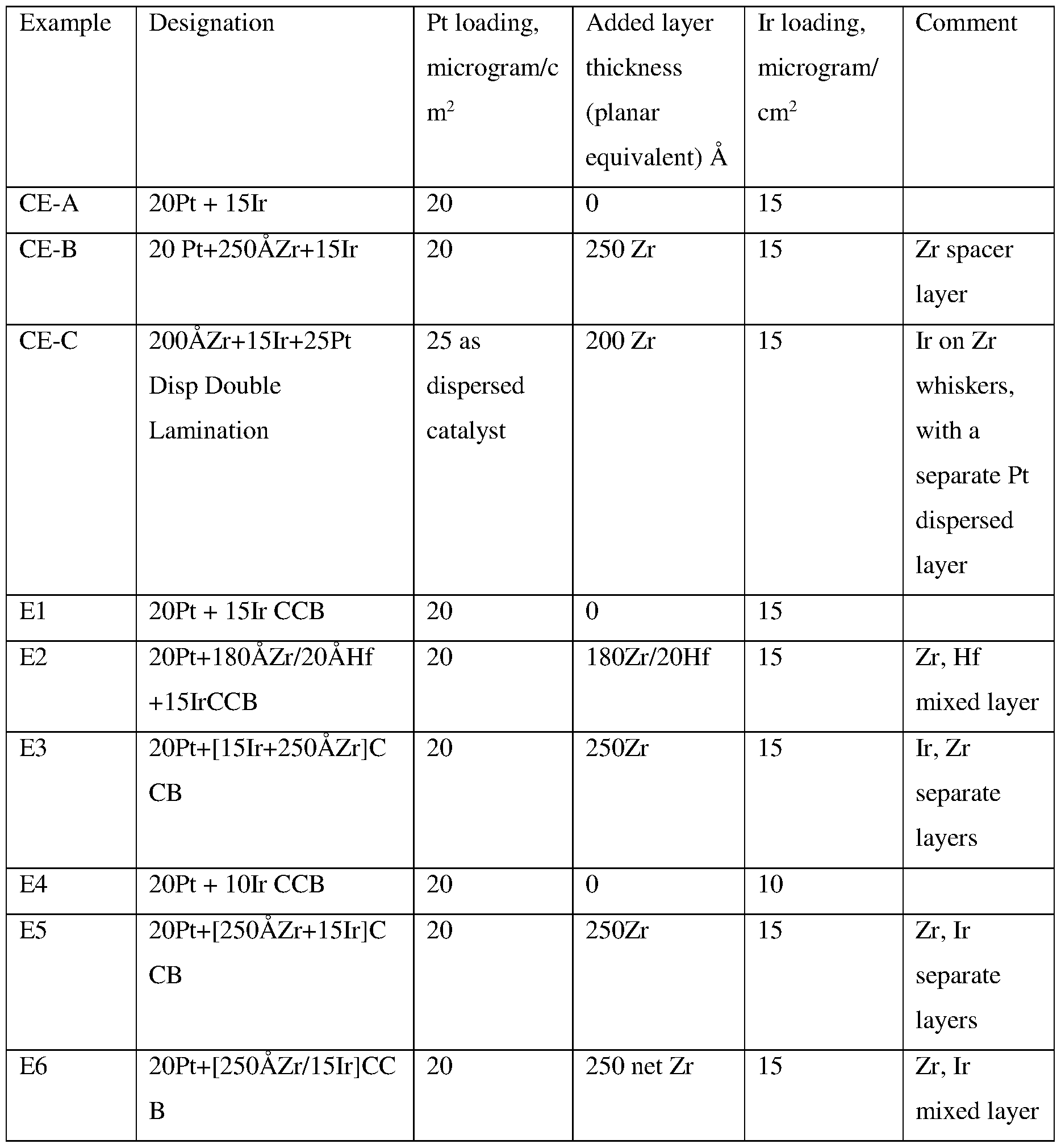
Claims
Priority Applications (6)
| Application Number | Priority Date | Filing Date | Title |
|---|---|---|---|
| US15/531,786 US10700372B2 (en) | 2014-12-15 | 2015-12-09 | Membrane electrode assembly |
| KR1020177019023A KR20170095296A (en) | 2014-12-15 | 2015-12-09 | Membrane electrode assembly |
| CN201580065900.7A CN107004862B (en) | 2014-12-15 | 2015-12-09 | Membrane electrode assembly |
| CA2971171A CA2971171A1 (en) | 2014-12-15 | 2015-12-09 | Membrane electrode assembly |
| JP2017531869A JP6890091B2 (en) | 2014-12-15 | 2015-12-09 | Membrane electrode assembly |
| EP15812927.0A EP3235039B1 (en) | 2014-12-15 | 2015-12-09 | Membrane electrode assembly |
Applications Claiming Priority (4)
| Application Number | Priority Date | Filing Date | Title |
|---|---|---|---|
| US201462091851P | 2014-12-15 | 2014-12-15 | |
| US62/091,851 | 2014-12-15 | ||
| US201462096097P | 2014-12-23 | 2014-12-23 | |
| US62/096,097 | 2014-12-23 |
Publications (1)
| Publication Number | Publication Date |
|---|---|
| WO2016100034A1 true WO2016100034A1 (en) | 2016-06-23 |
Family
ID=54851414
Family Applications (1)
| Application Number | Title | Priority Date | Filing Date |
|---|---|---|---|
| PCT/US2015/064698 WO2016100034A1 (en) | 2014-12-15 | 2015-12-09 | Membrane electrode assembly |
Country Status (7)
| Country | Link |
|---|---|
| US (1) | US10700372B2 (en) |
| EP (1) | EP3235039B1 (en) |
| JP (1) | JP6890091B2 (en) |
| KR (1) | KR20170095296A (en) |
| CN (1) | CN107004862B (en) |
| CA (1) | CA2971171A1 (en) |
| WO (1) | WO2016100034A1 (en) |
Cited By (6)
| Publication number | Priority date | Publication date | Assignee | Title |
|---|---|---|---|---|
| JP2018018808A (en) * | 2016-07-27 | 2018-02-01 | 財團法人工業技術研究院Industrial Technology Research Institute | Electrode catalyst and fuel cell using the same |
| WO2018226444A1 (en) * | 2017-06-05 | 2018-12-13 | 3M Innovative Properties Company | Electrode catalyst-containing dispersion compositions and articles therefrom |
| US11094953B2 (en) | 2015-05-26 | 2021-08-17 | 3M Innovative Properties Company | Electrode membrane assembly having an oxygen evolution catalyst electrodes, and methods of making and using the same |
| US11404702B2 (en) | 2018-04-04 | 2022-08-02 | 3M Innovative Properties Company | Catalyst comprising Pt, Ni, and Cr |
| US11476470B2 (en) | 2018-04-13 | 2022-10-18 | 3M Innovative Properties Company | Catalyst |
| US11955645B2 (en) | 2018-04-13 | 2024-04-09 | 3M Innovative Properties Company | Catalyst |
Families Citing this family (7)
| Publication number | Priority date | Publication date | Assignee | Title |
|---|---|---|---|---|
| JP7027874B2 (en) * | 2017-12-21 | 2022-03-02 | トヨタ自動車株式会社 | Separator for fuel cell and its manufacturing method |
| CN112771212A (en) | 2018-09-28 | 2021-05-07 | 3M创新有限公司 | Hydrogen fuel system |
| CN112534613B (en) * | 2019-11-27 | 2023-03-24 | 苏州擎动动力科技有限公司 | Membrane electrode, preparation method thereof and fuel cell |
| CN111082078B (en) * | 2019-12-30 | 2021-08-03 | 新源动力股份有限公司 | Preparation method of high-performance voltage reversal resistant membrane electrode assembly |
| US20220393211A1 (en) * | 2019-12-31 | 2022-12-08 | Kolon Industries, Inc. | Membrane-electrode assembly capable of improving reverse voltage durability of fuel cell, method for manufacturing same, and fuel cell including same |
| JP6799346B1 (en) * | 2020-05-21 | 2020-12-16 | 学校法人同志社 | Oxygen catalyst, electrodes using the oxygen catalyst, and electrochemical measurement method |
| KR20220049690A (en) * | 2020-10-15 | 2022-04-22 | 코오롱인더스트리 주식회사 | Membrane-Electrode Assembly Capable of Satisfying Both Requirements of Excellent Performance and High Durability and Fuel Cell Comprising The Same |
Citations (18)
| Publication number | Priority date | Publication date | Assignee | Title |
|---|---|---|---|---|
| US4340276A (en) | 1978-11-01 | 1982-07-20 | Minnesota Mining And Manufacturing Company | Method of producing a microstructured surface and the article produced thereby |
| US4568598A (en) | 1984-10-30 | 1986-02-04 | Minnesota Mining And Manufacturing Company | Article with reduced friction polymer sheet support |
| US4812352A (en) | 1986-08-25 | 1989-03-14 | Minnesota Mining And Manufacturing Company | Article having surface layer of uniformly oriented, crystalline, organic microstructures |
| US5039561A (en) | 1986-08-25 | 1991-08-13 | Minnesota Mining And Manufacturing Company | Method for preparing an article having surface layer of uniformly oriented, crystalline, organic microstructures |
| US5306579A (en) * | 1992-10-30 | 1994-04-26 | Aer Energy Resources, Inc. | Bifunctional metal-air electrode |
| US5338430A (en) | 1992-12-23 | 1994-08-16 | Minnesota Mining And Manufacturing Company | Nanostructured electrode membranes |
| US5879827A (en) | 1997-10-10 | 1999-03-09 | Minnesota Mining And Manufacturing Company | Catalyst for membrane electrode assembly and method of making |
| US5879828A (en) | 1997-10-10 | 1999-03-09 | Minnesota Mining And Manufacturing Company | Membrane electrode assembly |
| US6136412A (en) | 1997-10-10 | 2000-10-24 | 3M Innovative Properties Company | Microtextured catalyst transfer substrate |
| US20020004453A1 (en) | 1999-12-29 | 2002-01-10 | 3M Innovative Properties Company | Suboxide fuel cell catalyst for enhanced reformate tolerance |
| US6465041B1 (en) | 2001-12-19 | 2002-10-15 | 3M Innovative Properties Company | Method of making gas diffusion layers for electrochemical cells |
| US6624328B1 (en) | 2002-12-17 | 2003-09-23 | 3M Innovative Properties Company | Preparation of perfluorinated vinyl ethers having a sulfonyl fluoride end-group |
| US20040048466A1 (en) | 2002-09-06 | 2004-03-11 | Gore Makarand P. | Method and apparatus for forming high surface area material films and membranes |
| US7348088B2 (en) | 2002-12-19 | 2008-03-25 | 3M Innovative Properties Company | Polymer electrolyte membrane |
| US7419741B2 (en) | 2003-09-29 | 2008-09-02 | 3M Innovative Properties Company | Fuel cell cathode catalyst |
| US20100178582A1 (en) * | 2009-01-12 | 2010-07-15 | Gm Global Technology Operations, Inc. | Ionic layer with oxygen evolution reaction catalyst for electrode protection |
| US7901829B2 (en) | 2005-09-13 | 2011-03-08 | 3M Innovative Properties Company | Enhanced catalyst interface for membrane electrode assembly |
| US20150155567A1 (en) * | 2009-01-08 | 2015-06-04 | Daimler Ag | Reversal tolerant membrane electrode assembly for a fuel cell |
Family Cites Families (21)
| Publication number | Priority date | Publication date | Assignee | Title |
|---|---|---|---|---|
| US6610436B1 (en) | 1998-09-11 | 2003-08-26 | Gore Enterprise Holdings | Catalytic coatings and fuel cell electrodes and membrane electrode assemblies made therefrom |
| US7147959B2 (en) | 2002-05-31 | 2006-12-12 | Umicore Ag & Co. Kg | Process for the manufacture of membrane-electrode-assemblies using catalyst-coated membranes |
| JP2005216834A (en) | 2004-02-02 | 2005-08-11 | Matsushita Electric Ind Co Ltd | Polymer electrolyte type fuel cell |
| US7569082B2 (en) | 2004-10-07 | 2009-08-04 | Gm Global Technology Operations, Inc. | Manufacture of unitized electrode assembly for PEM fuel cells |
| JP2006134629A (en) * | 2004-11-04 | 2006-05-25 | Honda Motor Co Ltd | Electrode structure of solid polymer fuel cell |
| JP4993867B2 (en) * | 2005-03-07 | 2012-08-08 | ダイハツ工業株式会社 | Fuel cell |
| JP2006314871A (en) * | 2005-05-10 | 2006-11-24 | Toyota Motor Corp | Porphyrin based electrode catalyst |
| JP5034344B2 (en) * | 2006-07-06 | 2012-09-26 | 日産自動車株式会社 | Gas diffusion electrode and fuel cell using the same |
| KR20100120650A (en) | 2008-01-18 | 2010-11-16 | 엠엠아이-아이피씨오, 엘엘씨 | Composite fabrics |
| JP2009238685A (en) * | 2008-03-28 | 2009-10-15 | Panasonic Corp | Catalyst carrier and catalyst electrode |
| KR20100004495A (en) | 2008-07-04 | 2010-01-13 | 현대자동차주식회사 | Method for bonding mea and gdl of fuel cell stack |
| JP2010049933A (en) | 2008-08-21 | 2010-03-04 | Toyota Motor Corp | Manufacturing method for electrode of fuel cell |
| JP2010149008A (en) * | 2008-12-24 | 2010-07-08 | Toyota Motor Corp | Electrode catalyst |
| JP5519776B2 (en) * | 2009-04-23 | 2014-06-11 | スリーエム イノベイティブ プロパティズ カンパニー | Control of catalytic properties by intermixed inorganic materials |
| KR20110046907A (en) | 2009-10-29 | 2011-05-06 | (주)에프티이앤이 | Nano fiber filter media with nano fiber adhesive layer and method of making the same |
| US20130022890A1 (en) * | 2011-07-18 | 2013-01-24 | Ford Motor Company | Solid polymer electrolyte fuel cell with improved voltage reversal tolerance |
| CN106981669A (en) * | 2011-12-29 | 2017-07-25 | 3M创新有限公司 | Electrochemical cell electrode |
| JP2013164929A (en) * | 2012-02-09 | 2013-08-22 | Toyota Motor Corp | Method of producing electrode catalyst for fuel cell |
| JP5991670B2 (en) * | 2012-11-22 | 2016-09-14 | 国立研究開発法人物質・材料研究機構 | Method for producing small-diameter Ni3C nanoparticles, electrode catalyst containing small-diameter Ni3C nanoparticles, and method for producing the same |
| US9827709B2 (en) | 2012-12-21 | 2017-11-28 | The University Of Akron | Adhesive attachment discs |
| KR20160008192A (en) | 2013-04-23 | 2016-01-21 | 쓰리엠 이노베이티브 프로퍼티즈 캄파니 | Catalyst electrodes and method of making it |
-
2015
- 2015-12-09 WO PCT/US2015/064698 patent/WO2016100034A1/en active Application Filing
- 2015-12-09 US US15/531,786 patent/US10700372B2/en active Active
- 2015-12-09 CN CN201580065900.7A patent/CN107004862B/en active Active
- 2015-12-09 KR KR1020177019023A patent/KR20170095296A/en not_active Application Discontinuation
- 2015-12-09 JP JP2017531869A patent/JP6890091B2/en active Active
- 2015-12-09 EP EP15812927.0A patent/EP3235039B1/en active Active
- 2015-12-09 CA CA2971171A patent/CA2971171A1/en not_active Abandoned
Patent Citations (20)
| Publication number | Priority date | Publication date | Assignee | Title |
|---|---|---|---|---|
| US4340276A (en) | 1978-11-01 | 1982-07-20 | Minnesota Mining And Manufacturing Company | Method of producing a microstructured surface and the article produced thereby |
| US4568598A (en) | 1984-10-30 | 1986-02-04 | Minnesota Mining And Manufacturing Company | Article with reduced friction polymer sheet support |
| US4812352A (en) | 1986-08-25 | 1989-03-14 | Minnesota Mining And Manufacturing Company | Article having surface layer of uniformly oriented, crystalline, organic microstructures |
| US5039561A (en) | 1986-08-25 | 1991-08-13 | Minnesota Mining And Manufacturing Company | Method for preparing an article having surface layer of uniformly oriented, crystalline, organic microstructures |
| US5306579A (en) * | 1992-10-30 | 1994-04-26 | Aer Energy Resources, Inc. | Bifunctional metal-air electrode |
| US5338430A (en) | 1992-12-23 | 1994-08-16 | Minnesota Mining And Manufacturing Company | Nanostructured electrode membranes |
| US6319293B1 (en) | 1997-10-10 | 2001-11-20 | 3M Innovative Properties Company | Membrane electrode assembly |
| US6040077A (en) | 1997-10-10 | 2000-03-21 | 3M Innovative Properties Company | Catalyst for membrane electrode assembly and method of making |
| US6136412A (en) | 1997-10-10 | 2000-10-24 | 3M Innovative Properties Company | Microtextured catalyst transfer substrate |
| US5879827A (en) | 1997-10-10 | 1999-03-09 | Minnesota Mining And Manufacturing Company | Catalyst for membrane electrode assembly and method of making |
| US5879828A (en) | 1997-10-10 | 1999-03-09 | Minnesota Mining And Manufacturing Company | Membrane electrode assembly |
| US20020004453A1 (en) | 1999-12-29 | 2002-01-10 | 3M Innovative Properties Company | Suboxide fuel cell catalyst for enhanced reformate tolerance |
| US6465041B1 (en) | 2001-12-19 | 2002-10-15 | 3M Innovative Properties Company | Method of making gas diffusion layers for electrochemical cells |
| US20040048466A1 (en) | 2002-09-06 | 2004-03-11 | Gore Makarand P. | Method and apparatus for forming high surface area material films and membranes |
| US6624328B1 (en) | 2002-12-17 | 2003-09-23 | 3M Innovative Properties Company | Preparation of perfluorinated vinyl ethers having a sulfonyl fluoride end-group |
| US7348088B2 (en) | 2002-12-19 | 2008-03-25 | 3M Innovative Properties Company | Polymer electrolyte membrane |
| US7419741B2 (en) | 2003-09-29 | 2008-09-02 | 3M Innovative Properties Company | Fuel cell cathode catalyst |
| US7901829B2 (en) | 2005-09-13 | 2011-03-08 | 3M Innovative Properties Company | Enhanced catalyst interface for membrane electrode assembly |
| US20150155567A1 (en) * | 2009-01-08 | 2015-06-04 | Daimler Ag | Reversal tolerant membrane electrode assembly for a fuel cell |
| US20100178582A1 (en) * | 2009-01-12 | 2010-07-15 | Gm Global Technology Operations, Inc. | Ionic layer with oxygen evolution reaction catalyst for electrode protection |
Non-Patent Citations (19)
| Title |
|---|
| "High Dispersion and Electrocatalytic Properties of Platinum on Well-Aligned Carbon Nanotube Arrays", CARBON, vol. 42, 2004, pages 191 - 197 |
| "Proc. of the Fifth Int. Conf. on Rapidly Quenched Metals", 3 September 1984, ELSEVIER SCIENCE PUBLISHERS B.V., article "Rapidly Quenched Metals", pages: 1117 - 24 |
| BRUNO CHAUDRET, TOP ORGANOMET CHEM, vol. 16, 2005, pages 233 - 259 |
| CHEN G ET AL: "Effect of fabrication methods of bifunctional catalyst layers on unitized regenerative fuel cell performance", ELECTROCHIMICA ACTA, ELSEVIER SCIENCE PUBLISHERS, BARKING, GB, vol. 54, no. 23, 30 September 2009 (2009-09-30), pages 5454 - 5462, XP026236226, ISSN: 0013-4686, [retrieved on 20090421], DOI: 10.1016/J.ELECTACTA.2009.04.043 * |
| DOE HYDROGEN PROGRAM REVIEW, ADVANCE CATHODE CATALYSTS AND SUPPORTS FOR PEM FUEL CELLS, 8 June 2010 (2010-06-08) |
| GOTTESFELD; ZAWODZINSKI: "Advances in Electrochemical Science and Engineering", 1997, WILEY-VCH |
| J. MAT. SCI., vol. 25, 1990, pages 5257 - 68 |
| J. VAC. SCI. TECHNOL. A, vol. 5, no. 4, July 1987 (1987-07-01), pages 1914 - 16 |
| J. VAC. SCI. TECHNOL. A, vol. 6, no. 3, May 1988 (1988-05-01), pages 1907 - 11 |
| JOHNSON ET AL., ANAL. CHEM, vol. 82, 2010, pages 5718 - 5727 |
| JOHNSON ET AL., CHEMISTRY: A EUROPEAN JOURNAL, vol. 16, 2010, pages 14433 - 14438 |
| MATERIALS SCIENCE AND ENGINEERING, vol. A158, 1992, pages 1 - 6 |
| P.C. WAILES: "Organometallic Chemistry of Titanium, Zirconium, and Hafnium", ORGANOMETALLIC CHEMISTRY: A SERIES OF MONOGRAPHS |
| PHOTO. SCI. AND ENG, vol. 24, no. 4, July 1980 (1980-07-01), pages 211 - 16 |
| SEBASTIAN ALTMANN ET AL: "Bifunctional electrodes for unitised regenerative fuel cells", ELECTROCHIMICA ACTA, ELSEVIER SCIENCE PUBLISHERS, BARKING, GB, vol. 56, no. 11, 21 January 2011 (2011-01-21), pages 4287 - 4293, XP028480585, ISSN: 0013-4686, [retrieved on 20110128], DOI: 10.1016/J.ELECTACTA.2011.01.077 * |
| THIN SOLID FILMS, vol. 186, 1990, pages 327 - 47 |
| VALERIE MEILLE, APPLIED CATALYSIS A: GENERAL, vol. 315, 2006, pages 1 - 17 |
| WAN ET AL., SOLID STATE COMMUNICATIONS, vol. 121, 2002, pages 251 - 256 |
| WILSON; GOTTESFELD, J APPL. ELECTROCHEM., vol. 22, 1992, pages 1 - 7 |
Cited By (7)
| Publication number | Priority date | Publication date | Assignee | Title |
|---|---|---|---|---|
| US11094953B2 (en) | 2015-05-26 | 2021-08-17 | 3M Innovative Properties Company | Electrode membrane assembly having an oxygen evolution catalyst electrodes, and methods of making and using the same |
| JP2018018808A (en) * | 2016-07-27 | 2018-02-01 | 財團法人工業技術研究院Industrial Technology Research Institute | Electrode catalyst and fuel cell using the same |
| US10566631B2 (en) | 2016-07-27 | 2020-02-18 | Industrial Technology Research Institute | Electrocatalyst and fuel cell employing the same |
| WO2018226444A1 (en) * | 2017-06-05 | 2018-12-13 | 3M Innovative Properties Company | Electrode catalyst-containing dispersion compositions and articles therefrom |
| US11404702B2 (en) | 2018-04-04 | 2022-08-02 | 3M Innovative Properties Company | Catalyst comprising Pt, Ni, and Cr |
| US11476470B2 (en) | 2018-04-13 | 2022-10-18 | 3M Innovative Properties Company | Catalyst |
| US11955645B2 (en) | 2018-04-13 | 2024-04-09 | 3M Innovative Properties Company | Catalyst |
Also Published As
| Publication number | Publication date |
|---|---|
| CN107004862B (en) | 2021-02-05 |
| KR20170095296A (en) | 2017-08-22 |
| CA2971171A1 (en) | 2016-06-23 |
| US20170294669A1 (en) | 2017-10-12 |
| US10700372B2 (en) | 2020-06-30 |
| EP3235039B1 (en) | 2019-04-17 |
| JP6890091B2 (en) | 2021-06-18 |
| JP2018503942A (en) | 2018-02-08 |
| EP3235039A1 (en) | 2017-10-25 |
| CN107004862A (en) | 2017-08-01 |
Similar Documents
| Publication | Publication Date | Title |
|---|---|---|
| EP3235039B1 (en) | Membrane electrode assembly | |
| EP2770564B1 (en) | Barrier layer for corrosion protection in electrochemical devices | |
| EP2472657B1 (en) | Ternary platinum alloy catalyst | |
| EP2600968B1 (en) | Use of a platinum alloy catalyst for fuel cells | |
| KR102225982B1 (en) | Catalyst | |
| US20180006315A1 (en) | Porous adhesive networks in electrochemical devices | |
| CA3025595A1 (en) | Electrocatalyst material and process for preparing the same | |
| WO2013101595A1 (en) | Electrochemical cell electrode | |
| CN113424341B (en) | Catalyst for fuel cell | |
| US11476470B2 (en) | Catalyst | |
| AU2022315863A1 (en) | Oxygen evolution reaction catalyst |
Legal Events
| Date | Code | Title | Description |
|---|---|---|---|
| 121 | Ep: the epo has been informed by wipo that ep was designated in this application |
Ref document number: 15812927 Country of ref document: EP Kind code of ref document: A1 |
|
| WWE | Wipo information: entry into national phase |
Ref document number: 15531786 Country of ref document: US |
|
| REEP | Request for entry into the european phase |
Ref document number: 2015812927 Country of ref document: EP |
|
| ENP | Entry into the national phase |
Ref document number: 2017531869 Country of ref document: JP Kind code of ref document: A |
|
| ENP | Entry into the national phase |
Ref document number: 2971171 Country of ref document: CA |
|
| NENP | Non-entry into the national phase |
Ref country code: DE |
|
| ENP | Entry into the national phase |
Ref document number: 20177019023 Country of ref document: KR Kind code of ref document: A |