WO2015122352A1 - Treatment instrument - Google Patents
Treatment instrument Download PDFInfo
- Publication number
- WO2015122352A1 WO2015122352A1 PCT/JP2015/053267 JP2015053267W WO2015122352A1 WO 2015122352 A1 WO2015122352 A1 WO 2015122352A1 JP 2015053267 W JP2015053267 W JP 2015053267W WO 2015122352 A1 WO2015122352 A1 WO 2015122352A1
- Authority
- WO
- WIPO (PCT)
- Prior art keywords
- rotation
- unit
- rotating
- side rotation
- driving force
- Prior art date
Links
- 0 CCC(C)C[C@@](CCC1(CC)C(C)(C2)CCC*(CC)(*[*@](CC*(C(C)I)C(C*)(C3)C(C)I)C3=CCCCC3(C)C(CC)(CC(CC)*(C*(C*)=C4C(CCC[C@](**)C(CC*)CCC(C)(CC)*C*)C4)*(C)C*)CC(C)*3)CCC2C1)*C Chemical compound CCC(C)C[C@@](CCC1(CC)C(C)(C2)CCC*(CC)(*[*@](CC*(C(C)I)C(C*)(C3)C(C)I)C3=CCCCC3(C)C(CC)(CC(CC)*(C*(C*)=C4C(CCC[C@](**)C(CC*)CCC(C)(CC)*C*)C4)*(C)C*)CC(C)*3)CCC2C1)*C 0.000 description 2
Images


Classifications
-
- A—HUMAN NECESSITIES
- A61—MEDICAL OR VETERINARY SCIENCE; HYGIENE
- A61B—DIAGNOSIS; SURGERY; IDENTIFICATION
- A61B34/00—Computer-aided surgery; Manipulators or robots specially adapted for use in surgery
- A61B34/70—Manipulators specially adapted for use in surgery
- A61B34/71—Manipulators operated by drive cable mechanisms
-
- A—HUMAN NECESSITIES
- A61—MEDICAL OR VETERINARY SCIENCE; HYGIENE
- A61B—DIAGNOSIS; SURGERY; IDENTIFICATION
- A61B18/00—Surgical instruments, devices or methods for transferring non-mechanical forms of energy to or from the body
- A61B18/04—Surgical instruments, devices or methods for transferring non-mechanical forms of energy to or from the body by heating
- A61B18/08—Surgical instruments, devices or methods for transferring non-mechanical forms of energy to or from the body by heating by means of electrically-heated probes
- A61B18/082—Probes or electrodes therefor
- A61B18/085—Forceps, scissors
-
- A—HUMAN NECESSITIES
- A61—MEDICAL OR VETERINARY SCIENCE; HYGIENE
- A61B—DIAGNOSIS; SURGERY; IDENTIFICATION
- A61B18/00—Surgical instruments, devices or methods for transferring non-mechanical forms of energy to or from the body
- A61B18/04—Surgical instruments, devices or methods for transferring non-mechanical forms of energy to or from the body by heating
- A61B18/12—Surgical instruments, devices or methods for transferring non-mechanical forms of energy to or from the body by heating by passing a current through the tissue to be heated, e.g. high-frequency current
- A61B18/14—Probes or electrodes therefor
- A61B18/1442—Probes having pivoting end effectors, e.g. forceps
- A61B18/1445—Probes having pivoting end effectors, e.g. forceps at the distal end of a shaft, e.g. forceps or scissors at the end of a rigid rod
-
- A—HUMAN NECESSITIES
- A61—MEDICAL OR VETERINARY SCIENCE; HYGIENE
- A61B—DIAGNOSIS; SURGERY; IDENTIFICATION
- A61B17/00—Surgical instruments, devices or methods, e.g. tourniquets
- A61B17/28—Surgical forceps
- A61B17/29—Forceps for use in minimally invasive surgery
- A61B2017/2926—Details of heads or jaws
- A61B2017/2927—Details of heads or jaws the angular position of the head being adjustable with respect to the shaft
-
- A—HUMAN NECESSITIES
- A61—MEDICAL OR VETERINARY SCIENCE; HYGIENE
- A61B—DIAGNOSIS; SURGERY; IDENTIFICATION
- A61B17/00—Surgical instruments, devices or methods, e.g. tourniquets
- A61B17/32—Surgical cutting instruments
- A61B17/320068—Surgical cutting instruments using mechanical vibrations, e.g. ultrasonic
- A61B2017/320071—Surgical cutting instruments using mechanical vibrations, e.g. ultrasonic with articulating means for working tip
-
- A—HUMAN NECESSITIES
- A61—MEDICAL OR VETERINARY SCIENCE; HYGIENE
- A61B—DIAGNOSIS; SURGERY; IDENTIFICATION
- A61B34/00—Computer-aided surgery; Manipulators or robots specially adapted for use in surgery
- A61B34/70—Manipulators specially adapted for use in surgery
Definitions
- This invention relates to a treatment tool capable of treating living tissue.
- Japanese Patent Laid-Open No. 10-17489 discloses a treatment instrument that can rotate the end effector relative to the distal end of the sheath and maintain the rotated state by operating the operation unit. Has been.
- the end effector of this treatment tool can be opened and closed by operating the operation unit.
- the opening / closing operation of the end effector and the rotation operation with respect to the distal end of the sheath are independent. For this reason, when opening and closing an end effector, the rotation state of the end effector with respect to the distal end of the sheath can be maintained.
- the direction of the end effector can be changed with respect to the distal end of the sheath by rotating the operation lever, and after the end effector is changed to a predetermined position, the state of the end effector with respect to the distal end of the sheath
- An object of the present invention is to provide a treatment instrument capable of maintaining the position in a predetermined position.
- a treatment instrument includes a sheath having a distal end and a proximal end, and a longitudinal axis defined by the distal end and the proximal end, and an end provided to change the orientation of the sheath with respect to the distal end.
- An effector a driving force transmitting portion that is movably provided along the longitudinal axis in the sheath, and transmits a driving force that changes the orientation of the end effector from the proximal end to the distal end; and a proximal end of the driving force transmitting portion And a first rotating part that is rotatable about the first rotating shaft to move the driving force transmitting part along the longitudinal axis, and a first rotating part that is spaced in parallel to the first rotating shaft. It can be rotated around an axis of two rotation shafts, engages with the first rotation portion, transmits the rotation motion to the first rotation portion, and transmits the driving force to the driving force transmission portion. The orientation of the end effector is changed with respect to the sheath tip.
- a first rotation position that engages with the first rotation part and restricts the rotation of the first rotation part to prevent transmission of the rotation movement to the first rotation part and the drive.
- a second rotation unit that switches between a second rotation position that prevents the movement of the force transmission unit and maintains the position of the end effector with respect to the distal end of the sheath; the first rotation position and the second rotation position; And an operating body for switching the rotational position of the second rotating part.
- FIG. 1A is a schematic front view showing the treatment instrument according to the first to fifth embodiments and showing a state in which a holding portion is opened.
- FIG. 1B is a schematic front view showing the treatment instrument according to the first to fifth embodiments and showing a state where the holding unit is closed.
- FIG. 1C is a schematic cross-sectional view taken along line 1C-1C in FIG. 1B of the holding part of the treatment tool according to the first to fifth embodiments.
- FIG. 2A shows the treatment instrument according to the first to fifth embodiments, in which the operation lever disposed at the operation portion at the proximal end of the sheath is straightened along the longitudinal axis of the sheath, and is disposed at the distal end of the sheath.
- FIG. 2B shows the treatment instrument according to the first to fifth embodiments, in which the longitudinal direction of the operation lever arranged at the operation portion at the proximal end of the sheath begins to rotate in a direction away from the longitudinal axis
- FIG. 6 is a schematic top view showing a state in which the holding portion disposed at the distal end of the sheath is rotated to the right with respect to the distal end of the sheath for the first time by rotating rightward from the sheath base end toward the distal end. .
- FIG. 2C shows the treatment instrument according to the first to fifth embodiments, and begins to rotate the longitudinal direction of the operation lever arranged at the operation portion at the proximal end of the sheath in a direction away from the longitudinal axis.
- FIG. 6 is a schematic top view showing a state in which the holding portion disposed at the distal end of the sheath is rotated to the left with respect to the distal end of the sheath for the first time by rotating leftward from the sheath base end toward the distal end.
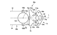
- FIG. 3A is a schematic diagram illustrating an input-side rotation unit of the one-way power transmission mechanism disposed inside the operation unit of the treatment instrument according to the first embodiment.
- FIG. 3B is a schematic diagram illustrating an output-side rotation unit of the one-way power transmission mechanism disposed inside the operation unit of the treatment instrument according to the first embodiment.
- FIG. 4A shows the one-way power transmission mechanism arranged inside the operation part of the treatment instrument according to the first embodiment, in which an operation lever is arranged along the longitudinal axis of the sheath, and a pair of connecting parts with the longitudinal axis. It is the schematic which shows the state which the 1st imaginary line which passes through orthogonally crosses.
- FIG. 4B shows a one-way power transmission mechanism arranged inside the operation portion of the treatment instrument according to the first embodiment, with the distal end of the operation lever turning to the left and the rear end turning to the right with respect to the longitudinal axis of the sheath.
- FIG. 4C shows the one-way power transmission mechanism arranged inside the operation part of the treatment instrument according to the first embodiment, with the distal end of the operation lever turning to the left and the rear end turning to the right with respect to the longitudinal axis of the sheath. Then, the input side rotation unit is rotated, and the pin on the input side rotation unit enters the engagement groove of the output side rotation unit to rotate the end effector while rotating the output side rotation unit. It is the schematic which shows a state.
- FIG. 4C shows the one-way power transmission mechanism arranged inside the operation part of the treatment instrument according to the first embodiment, with the distal end of the operation lever turning to the left and the rear end turning to the right with respect to the longitudinal axis of the sheath. Then, the input side rotation unit is rotated, and the pin on the input side rotation unit enters the engagement groove of the output side rotation unit to rotate the end effector while rotating the output side rotation unit.
- FIG. 4C shows the one-way power transmission mechanism arranged inside the operation part of the treatment instrument
- FIG. 4D shows the one-way power transmission mechanism arranged inside the operation unit of the treatment instrument according to the first embodiment, and the operation lever and the input side rotation unit are positioned along the longitudinal axis of the sheath as shown in FIG. 4A.
- FIG. 5 is a schematic view showing a modification of the rotating portion of the treatment instrument according to the first to fifth embodiments.
- FIG. 6 is a schematic diagram illustrating an output side rotation unit of the one-way power transmission mechanism disposed inside the operation unit of the treatment instrument according to the second embodiment.
- FIG. 7A is a schematic diagram illustrating an input-side rotation unit of a one-way power transmission mechanism disposed inside the operation unit of the treatment tool according to the third embodiment.
- FIG. 7B is a schematic diagram illustrating an input-side rotation unit of the one-way power transmission mechanism disposed inside the operation unit of the treatment tool according to the modification of the third embodiment.
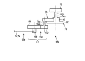
- FIG. 8A is a schematic top view showing a one-way power transmission mechanism arranged inside the operation unit of the treatment tool according to the fourth embodiment.
- FIG. 8B is a schematic side view showing a one-way power transmission mechanism arranged inside the operation unit of the treatment tool according to the fourth embodiment.
- FIG. 9A is a schematic top view showing a one-way power transmission mechanism arranged inside the operation unit of the treatment tool according to the fifth embodiment.
- FIG. 9B is a schematic side view showing a one-way power transmission mechanism arranged inside the operation unit of the treatment tool according to the fifth embodiment.
- the treatment instrument 10 includes a sheath 12, a driving force transmission unit 14, an end effector 16, and an operation unit 18.
- the sheath 12 is formed in a cylindrical shape by, for example, a stainless steel material.
- the sheath 12 has a distal end 12a and a proximal end 12b, and the longitudinal axis L is defined by the distal end 12a and the proximal end 12b.
- the end effector 16 includes, for example, a holding unit 32 (see FIGS. 1A to 1C) that can hold a living tissue, and an energy output unit 34 (see FIGS. 1A and 1C) that applies energy to the living tissue held by the holding unit 32 to perform treatment. 1C) and a rotating part 36 (see FIGS. 1A, 1B, and 2A to 2C) for opening and closing the holding part 32.
- the holding unit 32 includes a first holding member 42 having a first holding surface 42a and a second holding member 44 having a second holding surface 44a.
- the first and second holding members 42 and 44 are connected to an opening / closing lever 64 (to be described later) of the operation unit 18, and a driving force is transmitted by an opening / closing driving shaft (not shown) that is inserted through the inside of the sheath 12. Is done.
- the opening / closing drive shaft is preferably a wire, but a plurality of rod-shaped members are also preferably used. The plurality of rod-shaped members are connected to each other at a portion to be rotated.
- the energy output unit 34 is preferably disposed on both the first holding surface 42a and the second holding surface 44a, but is preferably disposed on either one.
- the energy output unit 34 can be set as appropriate, such as high-frequency energy using a high-frequency electrode, ultrasonic vibration energy generated by ultrasonic vibration generated from an ultrasonic vibrator, and thermal energy using a heater.
- the energy output unit 34 is preferably formed so as to be able to continuously apply energy to a living tissue, for example, substantially U-shaped.
- guide grooves 42b and 44b are formed inside the energy output unit 34, and a cutter (not shown) for cutting the biological tissue dehydrated by applying energy is inserted and removed.
- the cutter has flexibility so that it can be bent as the end effector 16 rotates.
- the rotating unit 36 rotates the end effector 16 with respect to the distal end 12a of the sheath 12 by the shaft member 36a, in other words, It is formed so that the direction of the end effector 16 can be changed with respect to the distal end 12 a of the sheath 12. That is, the end effector 16 is provided so as to be rotatable with respect to the distal end 12 a of the sheath 12, in other words, its direction can be changed.
- the driving force transmission unit 14 is provided inside the sheath 12 so as to be movable along the longitudinal axis L.
- the transmission unit 14 includes, for example, a pair of drive shafts 52 and 54 formed of a wire or a rod.
- the pair of drive shafts 52 and 54 cooperate with a base end 16a of the end effector 16 and a one-way power transmission mechanism 66a (described later) of the operation unit 18 to form a link mechanism 66b such as a known substantially parallelogram. .
- the driving force transmission unit 14 rotates the end effector 16 from the operation unit 18 with respect to the distal end 12a of the sheath 12 so that the driving force for changing the direction of the end effector 16 is directed from the proximal end to the distal end. Can be communicated.
- the operation unit 18 includes an operation unit main body 62 having a grip 62 a, an opening / closing lever 64 that relatively opens and closes the first and second holding members 42 and 44 of the end effector 16, and the end effector 16 at the distal end 12 a of the sheath 12.
- a rotation mechanism 66 that maintains a desired rotation state is provided.
- the rotation mechanism 66 is preferably used in combination with a one-way power transmission mechanism 66a and a link mechanism 66b such as a parallelogram.
- a known mechanism can be used as appropriate.
- the one-way power transmission mechanism 66 a is outside the operation unit main body 62 and is provided with an operation lever (driving force input unit) 72 as an operation body operated by a user (operator) of the treatment instrument 10, And an input-side rotation unit (second rotation unit) 74 that is rotated by the input of the driving force from the operation lever 72, and an output-side rotation unit that is connected to the driving force transmission unit 14 (first time). Moving part) 76.
- the one-way power transmission mechanism 66 a can transmit a driving force from the input side rotation unit 74 to one direction of the output side rotation unit 76, but the driving force is transmitted from the output side rotation unit 76 to the input side rotation unit 74. Transmission is suppressed or regulated.
- the operation lever 72 is preferably disposed at the proximal end 12 b of the sheath 12.
- the operation lever 72 is preferably disposed above the proximal end 12b of the sheath 12 when the opening and closing direction of the first and second holding members 42 and 44 is defined as the vertical direction.
- the operation lever 72 can be rotated about the rotation shaft 72 a as a fulcrum, and a driving force can be input to the input side rotation unit 74.
- the operation lever 72 is formed in a rod shape having a longitudinal direction parallel to the longitudinal axis L of the sheath 12 depending on the arrangement.
- the end effector 16 When the longitudinal direction of the operation lever 72 is parallel to the longitudinal axis L of the sheath 12, the end effector 16 is adjusted so as to be arranged straight along the longitudinal axis L with respect to the distal end 12 a of the sheath 12.
- the rotation angle of the end effector 16 is set to be larger with respect to the distal end 12a of the sheath 12 as the longitudinal direction of the operation lever 72 deviates from the longitudinal axis L of the sheath 12.
- the input side rotation unit 74 is rotatable about an input side rotation axis (center axis) 74 a orthogonal to the longitudinal axis L of the sheath 12. In other words, the input side rotation unit 74 can rotate around the axis of the input side rotation shaft 74a.
- the input side rotation shaft 74a of the input side rotation unit 74 is coaxial with the rotation shaft 72a of the operation lever 72. For this reason, the input side rotation unit 74 is rotated in conjunction with the operation lever 72 that is rotated by the user, and a driving force is applied.
- the input side rotation shaft (second rotation shaft) 74a is spaced in parallel to an output side rotation shaft (first rotation shaft) 76a described later.
- the operation lever 72 and the input side rotation unit 74 are prevented from rotating freely due to gravity or the like even when the output side rotation unit 76 does not exist.
- the operation unit main body 62 is supported so as to generate appropriate friction.
- an O-ring or the like is disposed between the operation unit main body 62 and the rotating shaft 72a, for example.
- the friction between the operation lever 72 and the operation unit main body 62 maintains the relative position in a state where the user releases the operation lever 72 and operates the operation lever 72 with respect to the operation unit main body 62.
- 72 is freely rotatable.
- the input side rotation unit 74 includes a pedestal 82, a plurality of pins (first engagement portions) 84 a and 84 b disposed on the pedestal 82, and an input cam disposed on the pedestal 82. 86.
- the plurality of pins 84 a and 84 b and the input cam 86 are arranged on one (front surface) of the two surfaces (front surface and back surface) of the base 82.
- the pedestal 82 is formed in a substantially rhombus having two diagonal lines (a short axis and a long axis).
- the input side rotation shaft 74a is located at the intersection of two diagonal lines of the pedestal 82, that is, located at the center of gravity.
- the plurality of pins 84 a and 84 b are located at positions close to the apex of the long axis of the two diagonal lines of the rhombus-shaped base 82.
- the plurality of pins 84a and 84b are on the opposite sides of the input side rotation shaft 74a and are equidistant from the input side rotation shaft 74a.
- the plurality of pins 84a and 84b are put in and out of engagement groove portions (first engagement groove portions) 114a and 114b, which will be described later, of the output side rotation portion 76 according to the rotation around the axis of the input side rotation shaft 74a. . For this reason, a driving force can be applied to the output side rotation unit 76 by the pins 84 a and 84 of the input side rotation unit 74.
- the input cam 86 is integrated with the pedestal 82.
- the input cam 86 has two convex portions (second convex portions) 92a and 92b as engaging portions (second engaging portions) whose normals are directed to opposite sides around the input side rotation shaft 74a, It has two recessed parts (second recessed parts) 94a, 94b directed to opposite sides with the input side rotating shaft 74a as a center.
- the pair of convex portions 92a and 92b are formed symmetrically with respect to the input side rotation shaft 74a.
- the convex portions 92a and 92 of the input-side rotary shaft rotating portion 74 include convex portions (second engagement groove portions) 92a and 92b that protrude along the radial direction of the rotary shaft 74a.
- the two recesses 94a and 94b are formed symmetrically with respect to the input side rotation shaft 74a.
- the two convex portions 92a and 92b have arcuate surfaces 96a and 96b with the input side rotation shaft 74a as the center.
- each arc surface 96a, 96b is in a range of approximately 90 degrees with the input side rotation shaft 74a as the center.
- the two concave portions 94a and 94b have edge portions 98a and 98b at positions close to the input-side rotation shaft 74a with respect to the circular arc surfaces 96a and 96b.
- edges 98a and 98b of the recesses 94a and 94b may be formed in an appropriate shape as long as they are formed in a concave shape with respect to the protrusions 92a and 92, but are preferably formed as arcuate surfaces. . It is also preferable that the edges 98a and 98b are formed, for example, in a substantially U shape.
- the pins 84a and 84b are more distal to the input-side rotation shaft 74a than the circular arc surfaces 96a and 96b of the convex portions 92a and 92b.
- the pins 84a and 84b are opposed to the edge portions 98a and 98b of the recesses 94a and 94b, and are positioned away from the regions extending radially beyond the circular arc surfaces 96a and 96b with the input-side rotation shaft 74a as the center. is there.
- the input side rotating unit 74 is symmetric with respect to the long axis L in FIG. 74a and the phantom line I passing through the pins 84a and 84b are preferably symmetric.
- the output side rotation part (output cam) 76 is rotatable about an output side rotation shaft (second central axis) 76a spaced in parallel with the input side rotation shaft 74a.
- the line segment that virtually connects the input-side rotation shaft 74a and the output-side rotation shaft 76a is preferably on the longitudinal axis L.
- the output side rotation part 76 is formed between the recesses (second engagement groove parts) 102a, 102b, 102c, preferably odd numbers of 3 or more, and the adjacent recesses (first recesses) 102a, 102b, 102c.
- the recessed part 102b is formed between the convex parts 104a and 104b.
- a concave portion 102a is formed between the connecting portion 106a and the convex portion 104a.
- the connecting portion 106b forms a concave portion 102c between the convex portion 104b.
- the connection parts 106a and 106b function as convex parts similarly to the convex parts 104a and 104b.
- a plurality of convex portions 92a and 92b of the input side rotation portion 74 are fitted into the concave portions 102a, 102b and 102c. Since the convex portions 104a and 104b are disposed between the concave portions 102a, 102b, and 102c, it is preferable that the number is an even number.
- the output side rotation part (output cam) 76 is orthogonal to the first imaginary line I1 passing through the pair of connection parts 106a and 106b, and passes through the rotation shaft 76a.
- the second virtual line I2 is symmetric with respect to the second virtual line I2.
- a concave portion 102b having a circular arc surface 112b described later is disposed on the second imaginary line I2.
- the recesses 102a, 102b, and 102c have arcuate surfaces (groove surfaces formed in an arcuate shape) 112a, 112b, and 112c centered on the input-side rotation shaft 74a, respectively.
- the output side rotation part 76 is provided with the recessed part (2nd engagement groove part) 102a, 102b, 102c dented along the radial direction of the rotating shaft 76a.
- the output side rotation part 76 has engagement groove parts 114a and 114b as cam grooves in a region between the convex parts 104a and 104b and the output side rotation shaft 76a. That is, the convex portions 104a and 104b have a plurality of engaging groove portions 114a and 114b in which pins 84a and 84b used as cam pins are taken in and out. And the entrance of engagement groove part 114a, 114b is formed in the distal with respect to the output side rotating shaft 76a among convex part 104a, 104b.
- the engagement groove portions 114a and 114b are preferably formed straight in the radial direction with respect to the output-side rotation shaft 76a.
- the input side rotation unit 74 Rather than the distance between the rotation shaft 74a and the pins 84a and 84b, the distance between the rotation shaft 74a of the input side rotation portion 74 and the innermost groove portions 114a and 114b of the output side rotation portion 76. The distance is longer.
- the circular arc surfaces 112a, 112b, and 112c are in the range of, for example, approximately 50 degrees with the output side rotation shaft 76a as the center in consideration of the convex portions 104a and 104b.
- the convex portions 104a and 104b are in a range of about 10 degrees, for example, with the output side rotation shaft 76a as the center.
- the output side rotation unit 76 is connected to the driving force transmission unit 14, that is, the base ends 52 a and 54 a of the drive shafts 52 and 54 are connected to the connection units 106 a and 106 b of the output side rotation unit 76. For this reason, when the output side rotation part 76 rotates around the axis of the output side rotation shaft 76a, the pair of drive shafts 52 and 54 of the drive force transmission unit 14 are moved along the longitudinal axis L inside the sheath 12. It is possible to make it.
- the neutral state is set.
- the operation lever 72 is rotated by minus 180 degrees from the state shown in FIG. 2A to the direction shown in FIG. 2B with respect to the neutral state.
- the end effector 16 is maintained, for example, in a state of being rotated by approximately plus 60 degrees. That is, in this embodiment, the state in which the operation lever 72 is rotated by minus 180 degrees is defined as one step.
- the end effector 16 rotates, for example, approximately plus 60 degrees in one step with respect to the neutral state. In this embodiment, for example, plus 60 degrees is the maximum rotation angle in the plus direction with respect to the neutral state.
- the end effector 16 is maintained in a state where it is rotated, for example, approximately minus 60 degrees. That is, in this embodiment, the state in which the operation lever 72 is rotated by 180 degrees is defined as one step.
- the end effector 16 rotates, for example, approximately minus 60 degrees in one step with respect to the neutral state. In this embodiment, for example, minus 60 degrees is the maximum rotation angle in the minus direction with respect to the neutral state.
- FIG. 4A to FIG. 4D the effect
- the operation lever 72 has a longitudinal axis arranged in a direction along the longitudinal axis L of the sheath 12, and the distal end 12a of the sheath 12 is placed.
- the end effector 16 is maintained in a straight neutral state.
- the arc surface 96a of one convex portion 92a of the convex portions 92a and 92b of the input cam 86 of the input side rotational portion 74 is out of the three concave portions 102a, 102b, and 102c of the output side rotational portion 76. It faces the circular arc surface 112b of the central recess 102b. And the convex part 92a is fitted by the recessed part 102b.
- an external force may be applied to the end effector 16 so as to deviate from the longitudinal axis L with respect to the distal end 12a of the sheath 12.
- the external force is transmitted from the end effector 16 to the output side rotation unit 76 via the drive shafts 52 and 54 of the link mechanism 66b.
- the output side rotation part 76 rotates around the axis
- no external force is transmitted to the input side rotation unit 74.
- the concave portion 102 b of the output side rotation unit 76 is approximately 50 degrees or less with respect to the central axis 76 a of the output side rotation unit 76. Even if the output-side rotation unit 76 rattles due to an external force applied to the end effector 16, it is limited to a range smaller than the angle (about ⁇ 25 degrees with respect to the longitudinal axis L). Therefore, the end effector 16 tries to maintain a neutral state with respect to the distal end 12 a of the sheath 12. That is, the position of the end effector 16 can be held with respect to the distal end 12 a of the sheath 12.
- the operation lever 72 is parallel to the longitudinal axis L of the sheath 12, for example, the front side to the left side (the lower side in FIGS. 4A to 4B), The rear side starts to rotate toward the right side (upper side in FIGS. 4A to 4B). In this embodiment, finally, as shown in FIGS. 2A and 2B, the operation lever 72 is rotated 180 degrees.
- the state in which the convex portion 92a of the input side rotational portion 74 is in contact with the concave portion 102b of the output side rotational portion 76 starts to be released.
- the pin 84a of the input side rotation part 74 moves from the entrance of the engagement groove part 114a toward the innermost part.
- the driving force is transmitted from the input side rotation unit 74 to the output side rotation unit 76, and the output side rotation unit 76 starts to rotate in the direction opposite to the input side rotation unit 74.
- the output side rotation unit 76 rotates, one drive shaft 52 is pulled toward the proximal end side, and the other drive shaft 54 is pushed toward the distal end side. Therefore, the end effector 16 starts to rotate toward the drive shaft 52 that is pulled with respect to the distal end 12 a of the sheath 12.
- the convex portion 92a of the input side turning portion 74 is the output side turning portion 76.
- the state of being in contact with the concave portion 102b (fitted state) is released.
- the concave portion 94 a of the input side rotation portion 74 faces the convex portion 104 a of the output side rotation portion 76.
- the concave portion 94a of the input side rotation portion 74 moves around the convex portion 104a of the output side rotation portion 76, but moves so as not to contact the convex portion 104a of the output side rotation portion 76 and comes into contact therewith. do not do.
- the pin 84a After the pin 84a enters the innermost part of the engaging groove 114a or the vicinity thereof, the pin 84a moves from the innermost part of the engaging groove 114a or the vicinity thereof to the entrance as the output side rotation part 76 further rotates. Move relatively. And the recessed part 94a of the input side rotation part 74 moves so that the convex part 104a of the output side rotation part 76 may be straddled.
- the pin 84a is ejected from the engaging groove 114a in a state in which the output side rotation portion 76 is rotated with respect to the neutral state (see FIG. 4A).
- the position of the pin 84a has moved from the position shown in FIG. 4A to the position shown in FIG. 4D.
- the convex circular arc surface 96b on the opposite side to the convex circular arc surface 96a of the input side rotation portion 74 in the neutral state is not the concave circular arc surface 112b in the center of the output side rotation portion 76 in the neutral state, but adjacent to the convex circular arc surface 96b.
- the concave arc surface 112a is in contact with and fitted.
- the position of the end effector 16 can be held with respect to the distal end 12a of the sheath 12 as described above. For this reason, it is prevented that the output side rotation part 76 rotates without permission with respect to the input side rotation part 74.
- the distal end of the end effector 16 is opposed to the biological tissue to be treated in the body cavity.
- the biological tissue to be treated and the tip of the end effector 16 are observed using an endoscope (not shown).
- the user operates the opening / closing lever 64 of the operation unit 18 to open the first and second holding members 42 and 44 in a relatively closed state, and appropriately moves the end effector 16 to thereby move the first and second holding members. It closes immediately after arrange
- External force may be applied to the end effector 16 that is rotated to the distal end 12a of the sheath 12.
- the position of the end effector 16 can be held with respect to the distal end 12 a of the sheath 12. That is, the end effector 16 tries to maintain a state where the end effector 16 is rotated with respect to the distal end 12 a of the sheath 12. For this reason, it is prevented that the output side rotation part 76 rotates without permission with respect to the input side rotation part 74.
- the end effector 16 when the end effector 16 is rotated at a predetermined rotation angle (in this embodiment, a neutral state and ⁇ 60 degrees) with respect to the distal end 12a of the sheath 12, It has rigidity to maintain the predetermined rotation angle.
- a predetermined rotation angle in this embodiment, a neutral state and ⁇ 60 degrees
- the end effector 16 As a usage of the end effector 16, there is a case where the end effector 16 pushes away the living tissue while appropriately rotating the end effector 16 with respect to the distal end 12a of the sheath 12. At this time, the rotation part 36 of the end effector 16 can be appropriately rotated via the operation lever 72, the input side rotation part 74, the output side rotation part 76, and the transmission part 14.
- the living tissue can be pushed away while the end effector 16 is rotated by operating the operation lever 72.
- the hand is released from the operation lever 72.
- the end effector 16 can be maintained at a predetermined angle. Therefore, the user can easily perform operations such as in a body cavity.
- the operation lever 72 rotates the input side rotation part 74 around the axis of the input side rotation shaft 74a, for example, inserts a pin (engagement part) 84a into the engagement groove part 114a, and turns the output side rotation part 76 to the output side.
- the pin (engagement portion) 84a is moved out of the engagement groove portion 114a to prevent the output side rotation portion 76 from rotating about the output side rotation shaft 76a.
- the position between the output side rotation unit 76 and the input side rotation unit 74 is fitted.
- the input side rotation unit 74 can be rotated.
- the end effector 16 can be rotated with respect to the distal end 12 a of the sheath 12 by rotating the operation lever 72, that is, the end effector with respect to the distal end 12 a of the sheath 12.
- the orientation of the end effector 16 can be changed.
- the rotation state of the end effector 16 with respect to the distal end 12a of the sheath 12 (the orientation of the end effector 16) is predetermined. Can be maintained in position.
- the operation lever 72 (input side rotation unit 74) of the treatment instrument 10 engages with the output side rotation unit 76 and transmits the rotation movement to the output side rotation unit 76, thereby driving force transmission unit. 14 to transmit the driving force to change the orientation of the end effector 16 with respect to the distal end of the sheath 12, and to engage the output-side rotation unit 76 to rotate the output-side rotation unit 76.
- a second rotational position that restricts and prevents transmission of the rotational motion to the output side rotational portion 76 and prevents movement of the driving force transmission portion 14 and maintains the position of the end effector 16 with respect to the distal end of the sheath 12. And can be switched. That is, the operation lever 72 can switch the rotation position of the input side rotation unit 74 between the first rotation position and the second rotation position.
- the pins 84 a and 84 b of the input side rotation unit 74 are engaged with the engagement grooves 114 a and 114 b of the output side rotation unit 76 at the first rotation position, and the input side rotation unit 74 is rotated. Then, the pins 84 a and 84 b press the engaging groove portions 114 a and 114 b, whereby the driving force is transmitted to the output side rotation portion 76.
- the amount of operation force for operating the operation lever 72 is required only by pressing the wall surface of the engagement groove 114a of the output side rotation portion 76 with the pin 84a, but a relatively small amount of operation force is sufficient. For this reason, the operation burden of the user when the operation lever 72 is rotated can be reduced.
- the second engagement portions 92a and 92b are engaged with the second engagement groove portions 102a, 102b, and 102c at the second rotation position, and the second engagement groove portion 102a is rotated with the rotation of the input side rotation portion 74. , 102b, 102c can slide relative to each other.
- the input side rotation part 74 is rotated to put the pins 84a and 84b in the engagement grooves 114a and 114b, and the output side rotation part 76 is moved around the output side rotation shaft 76a. It is possible to change the direction of the end effector 16 relative to the distal end of the sheath 12 by rotating the driving force transmission unit 14. Further, in the second rotation position, the input side rotation portion 74 is rotated to cause the pins 84a and 84b to be taken out from the engaging groove portions 114a and 114b, and the output side rotation portion 76 is moved around the output side rotation shaft 76a.
- the rotation of the drive force transmission unit 14 is suppressed by suppressing the rotation, and the output side rotation unit 76 and the input side rotation unit 74 are engaged so that the position of the end effector 16 is set with respect to the distal end of the sheath 12. Can be maintained.
- the one-way power transmission mechanism 66a disposed in the operation unit 18 of the treatment instrument 10 can transmit a driving force in one direction from the input side rotation unit 74 to the output side rotation unit 76. Transmission of driving force from the output side rotation unit 76 to the input side rotation unit 74 is restricted. For this reason, the end effector 16 is disposed in a desired position (the projections 92a and 92b of the input side rotation unit 74 are fitted in the recesses 102a, 102b, and 102c of the output side rotation unit 76).
- the operation is performed so that one of the convex portions 92a and 92b of the input side rotating portion 74 is fitted to face one of the concave portions 102a, 102b, and 102c of the output side rotating portion 76.
- the lever 72 When the lever 72 is operated, the end effector 16 is maintained at a predetermined angle with respect to the distal end 12 a of the sheath 12. As described above, when the end effector 16 is maintained at a predetermined angle with respect to the distal end 12a of the sheath 12, an external force is applied from the living tissue to the end effector 16.
- the end effector 16 according to this embodiment includes the sheath. It is possible to maintain a predetermined angle with respect to the twelve tips 12a.
- the end effector 16 can be rotated only when the user actively operates the rotation mechanism 66 to rotate the rotation lever 72, and the end effector 16 can be operated without operating the rotation mechanism 66. Can be passively rotated beyond an appropriate angle.
- transmission of the driving force from the output side rotation unit 76 to the input side rotation unit 74 is restricted. It is possible to prevent the operation lever 72 from rotating freely and being influenced by an external force applied to the end effector 16.
- the end effector 16 itself also has rigidity to maintain a predetermined rotation angle by suppressing the influence of external force applied to the input side rotation unit 74 and the operation lever 72.
- the output-side rotation unit 76 engages adjacent recesses 102a, 102b, 102c of the engagement grooves 114a, 114b that are directed to the input-side rotation unit 74 by rotation around the output-side rotation shaft 76a. Between the grooves.
- the input-side rotation unit 74 is engaged with a recess directed to the input-side rotation unit 74 among the plurality of recesses 102a, 102b, 102c of the output-side rotation unit 76 by rotation around the input-side rotation shaft 74a. It has a plurality of convex portions 92a and 92b that can be combined.
- the input-side rotation unit 74 is provided between adjacent projections among the plurality of input-side projections 92a and 92b and between the input-side rotation shaft 74a and the pins 84a and 84b.
- the output side convex portions 104a and 104b of the moving portion 76 have input side concave portions 94a and 94b that prevent interference between adjacent convex portions.
- the operation lever 72 when a driving force is input to the operation lever 72 and the driving force (rotational power) is transmitted from the input side rotation unit 74 to the output side rotation unit 76, the output side rotation is performed by the pin 84a of the input side rotation unit 74. In the state where the input side rotation unit 74 and the output side rotation unit 76 are rotated to predetermined positions, only the wall surface of the engaging groove 114a of the moving unit 76 is pressed. Further, the operation lever 72 and the input side rotation unit 74 are prevented from rotating. At this time, it is not necessary to hold the operation lever 72 in order to maintain the positions of the drive shafts 52 and 54. For this reason, according to the treatment instrument 10 according to this embodiment, the operation lever 72 can be operated with a relatively small amount of force when the operation lever 72 is rotated.
- the one-way power transmission mechanism 66 a allows the driving force from the operation lever (driving force input unit) 72 to be transmitted from the input side rotation unit 74 to the output side rotation unit 76 via the transmission unit 14.
- the end effector 16 can be rotated, that is, the orientation of the end effector 16 relative to the sheath 12 can be changed, and the position of the end effector 16 relative to the sheath 12 can be maintained.
- the transmission of power from the output side rotation unit 76 to the input side rotation unit 74 and the operation lever 72 via the end effector 16 and the transmission unit 14 is suppressed, and the position of the end effector 16 with respect to the sheath 12 can be maintained. it can.
- the operation lever 72 rotates the input side rotation portion 74 to put the pin 84a in the engagement groove portion 114a, and rotates the output side rotation portion 76 around the axis of the output side rotation shaft 76a to move the transmission portion 14.
- the input side rotation unit 74 can be rotated between a position where the output side rotation unit 76 and the input side rotation unit 74 are in contact with each other.
- a geneva mechanism is used as the one-way power transmission mechanism 66a.
- a driving force can be transmitted from the input-side rotation unit 74 to the output-side rotation unit 76, and the output-side rotation unit 76.
- Various mechanisms can be used as long as the mechanism is configured so that the driving force cannot be transmitted from the input side to the input side rotation unit 74.
- the rotating portion 36 may be formed as a bending tube 37 having a plurality of bending pieces 37a, 37b, 37c, 37d, and 37e, which are often used for a bending portion of an endoscope.
- the bending tube 37 can change the orientation of the end effector 16 with respect to the distal end 12 a of the sheath 12.
- the end effector 16 can be rotated with respect to the distal end 12a of the sheath 12 by rotating the operation lever 72, that is, the direction can be changed. After the effector 16 is rotated to a predetermined position, that is, the direction is changed, the rotation state of the end effector 16 relative to the distal end 12a of the sheath 12 (the direction of the end effector 16) can be maintained at the predetermined position.
- This embodiment is a modification of the first embodiment, and the same members as those described in the first embodiment or members having the same functions are denoted by the same reference numerals as much as possible, and detailed description thereof is omitted.
- the shape of the output side rotation unit 76 is deformed with respect to the output side rotation unit 76 shown in FIG. 3B.
- the output-side rotation unit 76 has five (three or more odd numbers) recesses 102a, 102b, 102c, 102d, and 102e, and four protrusions 104a, 104b, 104c, and 104d.
- the concave portion 102b is formed between the convex portions 104a and 104b
- the concave portion 102c is formed between the convex portions 104b and 104c
- the concave portion 102d is formed between the convex portions 104c and 104d.
- a concave portion 102a is formed between the connecting portion 106a and the convex portion 104a.
- connection part 106b forms a concave part 102d between the convex part 104d.
- connection parts 106a and 106b function as convex parts similarly to the convex parts 104a, 104b, 104c, and 104d.
- the recesses 102a, 102b, 102c, 102d, and 102e have arc surfaces 112a, 112b, 112c, 112d, and 112e, respectively, centered on the input side rotation shaft 74a.
- the circular arc surfaces 112a, 112b, 112c, 112d, and 112e are each formed in a range of about 30 degrees around the input side rotation shaft 74a.
- a concave portion 102c having an arc surface 112c is disposed on the second imaginary line I2.
- the convex portions 104a, 104b, 104c, and 104d have a plurality of engaging groove portions 114a, 114b, 114c, and 114d in which pins 84a and 84b (see FIG. 3A) of the input-side rotating portion 74 are taken in and out.
- the engagement groove portions 114a, 114b, 114c, and 114d are preferably formed straight in the radial direction with respect to the output-side rotation shaft 76a.
- the output side rotation unit 76 of this embodiment has a larger rotation angle with respect to the neutral state than the output side rotation unit 76 of the first embodiment. Therefore, in this embodiment, the end effector 16 rotates, for example, up to ⁇ 72 degrees.
- the output-side rotation unit 76 outputs more than the output-side rotation unit 76 described in the first embodiment.
- a rotation amount (rotation angle) with respect to the side rotation shaft 76a is small.
- the end effector 16 is maintained in a state of being rotated approximately 36 degrees with respect to the neutral state.
- the output side rotation shaft 76a is further rotated. At this time, the end effector 16 is maintained in a state of being rotated by approximately 72 degrees with respect to the neutral state.
- the angle (predetermined angle) at which the position of the end effector 16 with respect to the sheath 12 can be maintained is increased as compared with the case described in the first embodiment. it can. For this reason, the user can set the rotation angle of the end effector 16 with respect to the distal end 12a of the sheath 12 more finely, and can efficiently perform the workability of the treatment of the living tissue.
- the output side rotation unit 76 has five (odd 3 or more) recesses 102a, 102b, 102c, 102d, and 102e and four protrusions 104a, 104b, 104c, and 104d. explained.
- the output side rotation portion 76 is formed so as to have seven or nine (odd number) concave portions. If the number of the concave portions increases, it is also preferable that the output side rotation portion 76 be an even number instead of an odd number.
- This embodiment is a modification of the first and second embodiments, and the same members or members having the same functions as those described in the first and second embodiments are given the same reference numerals as much as possible. Detailed description is omitted.
- the shape of the input side rotation unit 74 is deformed with respect to the input side rotation unit 74 shown in FIG. 3A described in the first embodiment.
- the input side rotation unit 74 has a pedestal 82, a plurality of pins 84 a, 84 b, 84 c disposed on the pedestal 82, and an input cam 86 disposed on the pedestal 82.
- the pedestal 82 is formed in a substantially equilateral triangle.
- the input side rotation shaft 74a is located at the center of gravity of the pedestal 82.
- the plurality of pins 84 a, 84 b, 84 c are in positions close to the apex of the equilateral triangular base 82.
- the plurality of pins 84a, 84b, 84c are at positions that are approximately 120 degrees apart from each other about the input-side rotation shaft 74a and are equidistant from the input-side rotation shaft 74a. Then, the plurality of pins 84a, 84b, 84c are put in and out of engagement groove portions 114a, 114b, 114c, 114d, which will be described later, of the output side rotation portion 76 in accordance with the rotation around the axis of the input side rotation shaft 74a.
- the input cam 86 of the input side rotation unit 74 has three convex portions 92a whose normals are directed outward in the radial direction at positions separated by about 120 degrees about the input side rotation shaft 74a. 92b, 92c, and three concave portions 94a, 94b, 94c whose normals are directed outward in the radial direction at positions approximately 120 degrees apart from each other about the input side rotation shaft 74a.
- pins 84a, 84b, 84c are arranged at positions of approximately 120 degrees with respect to the input side central axis 74a.
- the convex portions 92a, 92b, and 92c are formed so as to be disposed in a region between adjacent pins 84a, 84b, and 84c. That is, the pins 84a, 84b, 84c are at positions facing the recesses 94a, 94b, 94c.
- the three convex portions 92a, 92b, and 92c have arcuate surfaces 96a, 96b, and 96c centered on the input side rotation shaft 74a, respectively.
- each arc surface 96a, 96b, 96c is in a range of approximately 60 degrees with the input side rotation shaft 74a as the center.
- the three concave portions 94a, 94b, and 94c have edge portions 98a, 98b, and 98c at positions close to the input side rotation shaft 74a with respect to the circular arc surfaces 96a, 96b, and 96c.
- edges 98a, 98b, and 98c of the recesses 94a, 94b, and 94c may be formed in an appropriate shape as long as they are formed in a concave shape with respect to the protrusions 92a, 92b, and 92c.
- the pins 84a, 84b, and 84c are more distal to the input-side rotation shaft 74a than the arcuate surfaces 96a, 96b, and 96c of the convex portions 92a, 92b, and 92c.
- the pins 84a, 84b, and 84c face the edges 98a, 98b, and 98c of the recesses 94a, 94b, and 94c, and extend in the radial direction with the input-side rotation shaft 74a as the center and beyond the circular arc surfaces 96a, 96b, and 96c. It is in a position that is out of the area.
- the input-side rotation unit 74 has a longitudinal line L that passes through the midpoint of the virtual line segment I connecting the pins 84a and 84b of the base 82 and coincides with the longitudinal axis L in FIG. Symmetry is preferred.
- the output side rotation unit 76 described in the second embodiment when the output side rotation unit 76 described in the second embodiment is used, when the input side rotation unit 74 according to this embodiment is rotated 120 degrees, it is described in the second embodiment.
- the output side rotation part 76 can be rotated approximately 36 degrees.
- the input-side rotating member 74 is also preferably configured such that the pedestal 82 has a rectangular shape such as a substantially square shape, and pins 84a, 84b, 84c, and 84d are formed in the vicinity of the corners. is there.
- the input cam 86 has four convex portions 92a, 92b, 92c, and 92d and four concave portions 94a, 94b, 94c, and 94d.
- the pins 84a, 84b, 84c, and 84d are opposed to the recesses 94a, 94b, 94c, and 94d.
- the input side rotation member 74 formed in this way can also be used similarly to the input side rotation member 74 described in the first and third embodiments.
- the input side rotation member 74 shown in FIG. 7B is rotated by an angle (approximately 90 degrees) smaller than that of the input side rotation unit 74 described in the first and third embodiments.
- the output-side rotation unit 76 can be rotated by approximately 60 degrees.
- the output side rotation part 76 demonstrated in 2nd Embodiment when used, when the input side rotation part 74 which concerns on this embodiment is rotated 90 degree
- FIGS. 8A and 8B This embodiment is a modification of the first to third embodiments, and the same members or members having the same functions as those described in the first to third embodiments are given the same reference numerals as much as possible. Detailed description is omitted.
- the operation unit 18 includes a gear mechanism 150.
- the gear mechanism 150 includes a first gear (here, a small gear) 152 connected to the output side rotation unit 76 and a second gear (here, a large gear) disposed between the pair of drive shafts 52 and 54. 154.
- the small gear 152 has a rotation axis (center axis) 152a common to the rotation axis 76a of the output side rotation unit 76.
- the rotation shaft (center shaft) 154a of the large gear 154 is supported by the operation unit main body 62, for example.
- the large gear 154 is integrated with the large gear 154 and has a pair of connecting portions 166a and 166b that rotate along with the rotation around the rotation shaft 154a.
- the base ends of the drive shafts 52 and 54 are connected to the pair of connecting portions 166a and 166b. For this reason, in this embodiment, the pair of connecting portions 106a and 106b are removed from the output-side rotating portion 76.
- the small gear 152 and the large gear 154 are meshed with each other.
- the operation lever 72 is operated, and the output side rotation unit 76 is connected to the output side rotation shaft 76a via the input side rotation unit 74.
- the rotation angle of the end effector 16 can be reduced to 1 / n with respect to the rotation angle of the output-side rotation unit 76.
- a finer step angle (approximately 60 degrees in FIG. 8A) can be reduced (1 / n) by the gear mechanism 150. That is, the rotation angle (bending angle) of the end effector 16 can be adjusted with a finer step angle.
- the gear mechanism 150 can adjust the movement amount in the direction along the longitudinal axis L of the driving force transmission unit 14 with respect to the rotation amount of the output side rotation unit 76.
- the first gear 152 is a small gear and the second gear 154 is a large gear having a larger diameter than the first gear 152.
- the magnitude relationship is reversed.
- FIGS. 9A and 9B This embodiment is a modification of the first to fourth embodiments, and the same members or members having the same functions as those described in the first to fourth embodiments are denoted by the same reference numerals as much as possible. Detailed description is omitted.
- the operation unit 18 has a gear mechanism 170.
- the gear mechanism 170 according to this embodiment is different from the gear mechanism 150 according to the fourth embodiment.
- the gear mechanism 170 includes a first gear (here, a large gear) 172 integrated with the operation lever 72, and a second gear (here, a small gear) 174 disposed on the input side rotation unit 74.
- the large gear 172 has a rotation axis (center axis) 172a common to the rotation axis 72a of the operation lever 72.
- the rotation shaft (center shaft) 174 a of the small gear 174 has a rotation shaft (center shaft) 174 a that is common to the rotation shaft 74 a of the input side rotation unit 74.
- the large gear 172 and the small gear 174 are meshed with each other.
- the ratio of the number of teeth of the large gear 172 and the small gear 174 is 1: n
- the operation lever 72 is operated and the input side rotation unit 74 is rotated around the axis of the input side rotation shaft 74a.
- the rotation angle of the input side rotation unit 74 can be reduced to 1 / n with respect to the rotation angle of the input side rotation unit 74 (for example, 180 degrees in this embodiment as shown in FIG. 9A). it can.
- the operating angle (approximately 180 degrees in FIG. 9A) can be reduced (1 / n) by the gear mechanism 170. That is, the rotation angle (bending angle) of the end effector 16 can be adjusted with a small operation angle.
Abstract
Description
第1実施形態について、図1Aから図4Dを用いて説明する。 Hereinafter, embodiments for carrying out the present invention will be described with reference to the drawings.
A first embodiment will be described with reference to FIGS. 1A to 4D.
開閉レバー64を操作してエンドエフェクタ16の第1及び第2保持部材42,44を相対的に開閉させる開閉機構は、公知の機構を適宜に用いることができる。 The
As the opening / closing mechanism for operating the opening / closing
なお、操作レバー72は仮に出力側回動部76が存在しないとしたときであっても、操作レバー72及び入力側回動部74が重力等により勝手に回動するのが防止されるように操作部本体62との間に適度な摩擦が生じるように支持されている。図示しないが、操作部本体62と回転軸72aとの間には、例えばOリング等が配置されていることが好ましい。操作レバー72と操作部本体62との間の摩擦は、ユーザが操作レバー72から手を放した状態で相対位置を維持し、操作レバー72を操作するときに操作部本体62に対して操作レバー72が自在に回動する程度である。 The input
Note that the
台座82はこの実施形態では2つの対角線(短軸及び長軸)を有する略菱形に形成されている。入力側回転軸74aは台座82の2つの対角線の交点の位置にあり、すなわち、重心の位置にある。
この実施形態では、複数のピン84a,84bは、菱形状の台座82の2つの対角線のうち長軸の頂点に近接する位置にある。複数のピン84a,84bは、入力側回転軸74aを中心として互いに反対側に、入力側回転軸74aに対して等距離の位置にある。そして、複数のピン84a,84bは、入力側回転軸74aの軸周りの回動に応じて出力側回動部76の後述する係合溝部(第1係合溝部)114a,114bに出し入れされる。このため、入力側回動部74のピン84a,84で出力側回動部76に駆動力を付与することができる。 As shown in FIG. 3A, the input
In this embodiment, the
In this embodiment, the plurality of
ここで、入力側回動部74の回動軸74a、出力側回動部76の係合溝部114aの入口から最奥部までの間を一直線上に配置したとき、入力側回動部74の回動軸74aとピン84a,84bとの間の距離よりも、入力側回動部74の回動軸74aと出力側回動部76の係合溝部114a,114bの最奥部との間の距離の方が長く形成されている。 The output
Here, when the space between the
この実施形態では、図2Aから図2C及び図4Aから図4Dに示すように、操作レバー72をニュートラル状態に対して、図2Aに示す状態から図2Bに示す方向に、マイナス180度回動させたとき、エンドエフェクタ16は例えば略プラス60度回動した状態で維持される。すなわち、この実施形態では、操作レバー72をマイナス180度回動させた状態を1つのステップとする。そして、エンドエフェクタ16はニュートラル状態に対して1つのステップにより例えば略プラス60度回動する。この実施形態ではニュートラル状態に対して例えばプラス60度がプラス方向の最大回動角度である。 Here, when the
In this embodiment, as shown in FIGS. 2A to 2C and FIGS. 4A to 4D, the
例えば体腔内等にエンドエフェクタ16を挿入する場合、図2A及び図4Aに示すように、操作レバー72がシース12の長手軸Lに沿った方向に長手軸を配置し、シース12の先端12aに対してエンドエフェクタ16が真っ直ぐのニュートラル状態に維持する。
このとき、入力側回動部74の入力カム86の凸部92a,92bのうちの一方の凸部92aの円弧面96aは、出力側回動部76の3つの凹部102a,102b,102cのうち、中央の凹部102bの円弧面112bに対向している。そして、凸部92aは凹部102bに嵌合されている。 Next, the effect | action of the
For example, when the
At this time, the
このとき、図4Dに示すように、ピン84aは出力側回動部76をニュートラル状態(図4A参照)に対して回動させた状態で係合溝部114aから出される。この実施形態では、ピン84aの位置は、図4Aに示す位置から図4Dに示す位置に移動している。そして、ニュートラル状態の入力側回動部74の凸状円弧面96aに対して反対側の凸状円弧面96bは、ニュートラル状態の出力側回動部76の中央の凹状円弧面112bではなく、隣接した凹状円弧面112aに当接して嵌合されている。このとき、上述したのと同様に、シース12の先端12aに対してエンドエフェクタ16の位置を保持することができる。このため、入力側回動部74に対して出力側回動部76が勝手に回動することが防止されている。 Immediately before the
At this time, as shown in FIG. 4D, the
操作レバー72は、入力側回動部74を入力側回転軸74aの軸周りに回動させて例えばピン(係合部)84aを係合溝部114aに入れて出力側回動部76を出力側回転軸76aの軸周りに回動させて駆動力伝達部14を移動させてエンドエフェクタ16をシース12の先端12aに対して回動させる位置と、入力側回動部74を入力側回転軸74aの軸周りに回動させてピン(係合部)84aを係合溝部114aから出させて出力側回動部76を出力側回転軸76aの軸周りに回動させるのを抑制して駆動力伝達部14の移動を抑制するとともにエンドエフェクタ16の位置をシース12の先端12aに対して維持するために出力側回動部76と入力側回動部74とが嵌合する位置との間を入力側回動部74を回動させることができる。
この実施形態に係る処置具10によれば、操作レバー72を回動操作することによりシース12の先端12aに対してエンドエフェクタ16を回動可能、すなわち、シース12の先端12aに対してエンドエフェクタ16の向きを変更可能で、エンドエフェクタ16を所定の位置に回動させすなわち向きを変更させた後はシース12の先端12aに対するエンドエフェクタ16の回動状態(エンドエフェクタ16の向き)を所定の位置に維持することができる。すなわち、この処置具10の操作レバー72(入力側回動部74)は、出力側回動部76に係合して出力側回動部76にその回動運動を伝達させて駆動力伝達部14に駆動力を伝達させてシース12の先端に対してエンドエフェクタ16の向きを変更させる第1回転位置と、出力側回動部76に係合して出力側回動部76の回動を規制して出力側回動部76にその回動運動の伝達を防止して駆動力伝達部14の移動を防止してシース12の先端に対してエンドエフェクタ16の位置を維持する第2回転位置とを切り替え可能である。すなわち、操作レバー72は、第1回転位置と第2回転位置との間で入力側回動部74の回転位置を切り替え可能である。 As described above, according to this embodiment, the following can be said.
The
According to the
回動部36に湾曲管37を用いた場合であっても、操作レバー72を回動操作することによりシース12の先端12aに対してエンドエフェクタ16を回動可能すなわち向きを変更可能で、エンドエフェクタ16を所定の位置に回動させすなわち向きを変更させた後はシース12の先端12aに対するエンドエフェクタ16の回動状態(エンドエフェクタ16の向き)を所定の位置に維持することができる。 In this embodiment, an example in which the
Even when the bending
台座82はこの実施形態では略正三角形に形成されている。入力側回転軸74aは台座82の重心の位置にある。
この実施形態では、複数のピン84a,84b,84cは、正三角形状の台座82の頂点に近接する位置にある。複数のピン84a,84b,84cは、入力側回転軸74aを中心として互いに略120度離れた位置であって、入力側回転軸74aに対して等距離の位置にある。そして、複数のピン84a,84b,84cは、入力側回転軸74aの軸周りの回動に応じて出力側回動部76の後述する係合溝部114a,114b,114c,114dに出し入れされる。 The input
In this embodiment, the
In this embodiment, the plurality of
Claims (19)
- 先端及び基端と、先端及び基端により規定される長手軸とを有するシースと、
前記シースの先端に対してその向きを変更可能に設けられたエンドエフェクタと、
前記シース内に前記長手軸に沿って移動可能に設けられ前記エンドエフェクタの向きを変更させる駆動力を基端から先端に伝達する駆動力伝達部と、
前記駆動力伝達部の基端に連結され、前記駆動力伝達部を前記長手軸に沿って移動させるために第1回転軸の軸周りに回動可能な第1回動部と、
前記第1回転軸に平行に離間した第2回転軸の軸周りに回動可能で、前記第1回動部に係合して前記第1回動部にその回動運動を伝達させて前記駆動力伝達部に前記駆動力を伝達させて前記シースの先端に対して前記エンドエフェクタの向きを変更させる第1回転位置と、前記第1回動部に係合して前記第1回動部の回動を規制して前記第1回動部にその回動運動の伝達を防止して前記駆動力伝達部の移動を防止して前記シースの先端に対して前記エンドエフェクタの位置を維持する第2回転位置とを切り替える第2回動部と、
前記第1回転位置と前記第2回転位置との間で前記第2回動部の回転位置を切り替える操作体と
を有する処置具。 A sheath having a distal end and a proximal end, and a longitudinal axis defined by the distal end and the proximal end;
An end effector provided to be able to change its orientation with respect to the distal end of the sheath;
A driving force transmitting portion that is provided in the sheath so as to be movable along the longitudinal axis and transmits a driving force for changing the direction of the end effector from the proximal end to the distal end;
A first rotation unit coupled to a base end of the driving force transmission unit and rotatable about an axis of a first rotation shaft to move the driving force transmission unit along the longitudinal axis;
It can be rotated around an axis of a second rotating shaft that is spaced in parallel to the first rotating shaft, and engages with the first rotating portion to transmit the rotating motion to the first rotating portion. A first rotation position for transmitting the driving force to the driving force transmission unit to change the orientation of the end effector with respect to the distal end of the sheath; and the first rotation unit engaged with the first rotation unit. The rotation of the end effector is restricted to prevent transmission of the rotational movement to the first rotation part, thereby preventing the movement of the driving force transmission part and maintaining the position of the end effector with respect to the distal end of the sheath. A second rotation unit that switches between the second rotation positions;
A treatment instrument comprising: an operating body that switches a rotation position of the second rotation unit between the first rotation position and the second rotation position. - 前記第1回動部は、第1係合溝部を備え、
前記第2回動部は、前記第1係合溝部に係合可能な第1係合部を備え、
前記第1係合部は、前記第1回転位置において、前記第1係合溝部に係合し、前記第2回動部の回転に伴って前記第1係合部が前記第1係合溝部を押圧することで前記駆動力が前記第1回動部に伝達される、請求項1に記載の処置具。 The first rotating part includes a first engaging groove part,
The second rotating part includes a first engaging part that can be engaged with the first engaging groove part,
The first engagement portion engages with the first engagement groove portion at the first rotation position, and the first engagement portion is rotated along with the rotation of the second rotation portion. The treatment tool according to claim 1, wherein the driving force is transmitted to the first rotation unit by pressing the button. - 前記第1回動部は、前記第1回転軸の径方向に凹んだ第2係合溝部を備え、
前記第2回動部は、前記第2回転軸の径方向に突出した第2係合部を備え、
前記第2係合部は、前記第2回転位置において、前記第2係合溝部に係合し、前記第2回動部の回転に伴って前記第2係合溝部に対して相対的に摺動する、請求項2に記載の処置具。 The first rotating part includes a second engaging groove part recessed in a radial direction of the first rotating shaft,
The second rotating part includes a second engaging part protruding in a radial direction of the second rotating shaft,
The second engagement portion engages with the second engagement groove portion at the second rotation position, and slides relatively with respect to the second engagement groove portion as the second rotation portion rotates. The treatment tool according to claim 2, which moves. - 前記第2係合部は、前記第2回転軸を中心とする円弧面を備え、
前記第2係合溝部は、前記第2回転軸を中心とする円弧状に形成された溝面を備える、請求項3に記載の処置具。 The second engagement portion includes an arc surface centered on the second rotation axis,
The treatment tool according to claim 3, wherein the second engagement groove portion includes a groove surface formed in an arc shape with the second rotation axis as a center. - 前記第1回動部は複数の係合溝部を有し、
前記第2回動部は前記第2回転軸の軸回りの回動に応じて前記複数の係合溝部に出し入れされる複数のピンを有し、
前記第1回転位置において、前記第2回動部を回動させて前記ピンを前記係合溝部に入れて前記第1回動部を前記第1回転軸の軸周りに回動させて前記駆動力伝達部を移動させて前記エンドエフェクタを前記シースの先端に対して向きを変更させ、
前記第2回転位置において、前記第2回動部を回動させて前記ピンを前記係合溝部から出させて前記第1回動部を前記第1回転軸の軸周りに回動させるのを抑制して前記駆動力伝達部の移動を抑制するとともに、前記第1回動部と前記第2回動部が係合して前記エンドエフェクタの位置を前記シースの先端に対して維持する、請求項1に記載の処置具。 The first rotating part has a plurality of engaging groove parts,
The second rotating part has a plurality of pins that are put into and out of the plurality of engaging groove parts according to the rotation around the axis of the second rotating shaft,
In the first rotation position, the second rotation part is rotated, the pin is inserted into the engagement groove part, and the first rotation part is rotated around the axis of the first rotation axis to drive the drive. Moving the force transmitting portion to change the direction of the end effector with respect to the distal end of the sheath;
In the second rotation position, the second rotation part is rotated so that the pin is taken out from the engagement groove part, and the first rotation part is rotated around the axis of the first rotation axis. And suppressing the movement of the driving force transmitting unit, and the first rotating unit and the second rotating unit are engaged to maintain the position of the end effector with respect to the distal end of the sheath. Item 2. The treatment tool according to Item 1. - 前記第1回動部は、それぞれ係合溝部を有する複数の第1凸部と、前記複数の第1凸部のうちの隣接する第1凸部間に設けられ、前記第1回転軸の軸周りの回転により前記第2回動部に向けられる複数の第1凹部とを有し、
前記第2回動部は、前記第1回動部の前記複数の第1凹部のうち前記第2回動部に向けられた凹部に前記第2回転軸の軸周りの回動により係合可能な複数の第2凸部を有する、請求項1に記載の処置具。 The first rotating portion is provided between a plurality of first convex portions each having an engaging groove portion and an adjacent first convex portion of the plurality of first convex portions, and the axis of the first rotation shaft A plurality of first recesses directed to the second rotating part by rotation around,
The second rotating portion can be engaged with a recess directed to the second rotating portion among the plurality of first recesses of the first rotating portion by rotating around the axis of the second rotating shaft. The treatment tool according to claim 1, further comprising a plurality of second convex portions. - 前記第2回動部は、第1係合部を備え、前記複数の第2凸部のうち隣接する第2凸部の間で、かつ、前記第2回転軸と前記第1係合部との間に設けられ、前記第1回動部の前記第1凸部のうち、隣接する凸部の間の干渉を防止する第2凹部を有する、請求項6に記載の処置具。 The second rotating portion includes a first engaging portion, and between the adjacent second convex portions among the plurality of second convex portions, and the second rotating shaft and the first engaging portion. The treatment tool according to claim 6, further comprising: a second concave portion provided between the first convex portions of the first rotating portion and preventing interference between adjacent convex portions.
- 前記第2回動部の前記第2凸部は、前記第2回転軸を中心とする凸状円弧面を有し、
前記第1回動部の前記第1凹部は、前記凸状円弧面が嵌合される凹状円弧面を有する、請求項6に記載の処置具。 The second convex portion of the second rotating portion has a convex arc surface centered on the second rotation axis,
The treatment tool according to claim 6, wherein the first concave portion of the first rotating portion has a concave arc surface into which the convex arc surface is fitted. - 前記第2回動部は、第1係合部を備え、
前記第1係合部は、前記凸状円弧面よりも前記第2回転軸に対して遠位にあり、かつ、前記第2回転軸を中心とし前記凸状円弧面を超えて径方向に延出される領域から外れた位置にある、請求項8に記載の処置具。 The second rotating part includes a first engaging part,
The first engaging portion is more distal to the second rotation axis than the convex arc surface, and extends in the radial direction with the second rotation axis as a center and beyond the convex arc surface. The treatment tool according to claim 8, wherein the treatment tool is located at a position deviated from a region to be taken out. - 前記第2回動部は、前記第2回転軸を中心として90度、120度及び180度の少なくとも一方の位置に前記第2凸部を有する、請求項6に記載の処置具。 The treatment tool according to claim 6, wherein the second rotating part has the second convex part at at least one of 90 degrees, 120 degrees, and 180 degrees about the second rotation axis.
- 前記エンドエフェクタが前記シースの前記長手軸に沿って真っ直ぐに延出されたニュートラル状態に対して、前記第2回動部が前記第2回転軸の軸周りに所定角度回動されると、前記第1回動部は前記第1回転軸の軸周りに所定角度回動される、請求項1に記載の処置具。 When the second rotation part is rotated by a predetermined angle around the axis of the second rotation axis with respect to the neutral state in which the end effector extends straight along the longitudinal axis of the sheath, The treatment tool according to claim 1, wherein the first rotation unit is rotated by a predetermined angle around the axis of the first rotation axis.
- 前記操作体と前記第2回動部との間に、前記操作体の回動量に対して前記第2回動部の回動量を調整する歯車機構を具備する、請求項1に記載の処置具。 The treatment tool according to claim 1, further comprising a gear mechanism that adjusts a rotation amount of the second rotation portion with respect to a rotation amount of the operation body between the operation body and the second rotation portion. .
- 前記第1回動部と前記駆動力伝達部との間に前記第1回動部の回動量に対して前記駆動力伝達部の前記長手軸に沿った方向の移動量を調整する歯車機構を具備する、請求項1に記載の処置具。 A gear mechanism that adjusts a movement amount of the driving force transmission unit in a direction along the longitudinal axis with respect to a rotation amount of the first rotation unit between the first rotation unit and the driving force transmission unit; The treatment tool according to claim 1, further comprising:
- 前記駆動力伝達部は、前記第1回動部と前記エンドエフェクタとの間を駆動する駆動軸を有する、請求項1に記載の処置具。 The treatment tool according to claim 1, wherein the driving force transmission unit includes a driving shaft that drives between the first rotating unit and the end effector.
- 前記エンドエフェクタは、生体組織を保持可能な保持部と、前記保持部に設けられ前記保持部に保持された生体組織にエネルギを付加して処置するエネルギ出力部とを有する、請求項1に記載の処置具。 The end effector includes: a holding unit capable of holding a living tissue; and an energy output unit that is provided in the holding unit and applies energy to the living tissue held in the holding unit to perform treatment. Treatment tool.
- 先端及び基端と、先端及び基端により規定される長手軸とを有するシースと、
前記シースの先端に対してその向きを変更可能に設けられたエンドエフェクタと、
前記シース内に前記長手軸に沿って移動可能に設けられ前記エンドエフェクタの向きを変更させる駆動力を基端から先端に伝達する駆動力伝達部と、
前記長手軸に対して直交する第1回転軸を支点として回動される入力側回動部と、前記入力側回動部に駆動力を入力可能な駆動力入力部と、前記第1回転軸に対して平行に離間した第2回転軸を支点として回動可能で前記駆動力伝達部に連結された出力側回動部とを有し、前記駆動力入力部による駆動力が前記入力側回動部から前記出力側回動部に伝達されるのを許容して前記駆動力伝達部を介して前記エンドエフェクタの向きを変更させることが可能かつ前記シースに対する前記エンドエフェクタの位置を維持することが可能で、前記エンドエフェクタ、前記駆動力伝達部を介して前記出力側回動部から前記入力側回動部及び前記駆動力入力部への動力の伝達を抑制し前記シースに対するエンドエフェクタの位置を維持する一方向動力伝達機構と
を具備する、処置具。 A sheath having a distal end and a proximal end, and a longitudinal axis defined by the distal end and the proximal end;
An end effector provided to be able to change its orientation with respect to the distal end of the sheath;
A driving force transmitting portion that is provided in the sheath so as to be movable along the longitudinal axis and transmits a driving force for changing the direction of the end effector from the proximal end to the distal end;
An input-side rotation unit that is rotated about a first rotation axis that is orthogonal to the longitudinal axis, a driving force input unit that can input a driving force to the input-side rotation unit, and the first rotation shaft And an output-side rotation unit connected to the driving force transmission unit, and the driving force by the driving force input unit is rotated on the input side. It is possible to change the direction of the end effector via the driving force transmission unit while allowing the transmission to be transmitted from the moving unit to the output side rotation unit, and to maintain the position of the end effector with respect to the sheath The position of the end effector relative to the sheath can be suppressed by suppressing transmission of power from the output side rotation unit to the input side rotation unit and the driving force input unit via the end effector and the driving force transmission unit. Maintain one-way power transmission ; And a structure, the treatment instrument. - 前記入力側回動部は、前記入力側回動部の回動に伴って前記出力側回動部に駆動力を付与するピンと、前記第1回転軸と前記ピンとの間に形成された凹部と、前記凹部に隣接した凸状円弧面とを有し、
前記出力側回動部は、前記ピンを出し入れ可能で前記ピンが入れられた状態で前記入力側回動部の回動力が前記出力側回動部に伝達され、かつ、前記凹部により前記入力側回動部の回動の際の干渉が防止される係合溝部と、前記ピンが前記係合溝部から出された状態で前記凸状円弧面に当接され前記出力側回動部から前記入力側回動部への動力の伝達を抑制する凹状円弧面とを有する、請求項16に記載の処置具。 The input-side rotating unit includes a pin that applies a driving force to the output-side rotating unit as the input-side rotating unit rotates, and a recess formed between the first rotating shaft and the pin. A convex arc surface adjacent to the recess,
The output-side rotation unit is capable of inserting and removing the pin, and the rotational force of the input-side rotation unit is transmitted to the output-side rotation unit in a state in which the pin is inserted. An engagement groove portion that prevents interference during rotation of the rotation portion, and the pin is brought into contact with the convex arcuate surface in a state of being protruded from the engagement groove portion, and the input from the output-side rotation portion The treatment tool according to claim 16, further comprising a concave arcuate surface that suppresses transmission of power to the side rotation unit. - 前記出力側回動部の前記係合溝部及び前記凹状円弧面は互いに隣接している、請求項17に記載の処置具。 The treatment instrument according to claim 17, wherein the engagement groove portion and the concave arc surface of the output side rotation portion are adjacent to each other.
- 前記出力側回動部の前記係合溝部及び前記凹状円弧面は、前記出力側回動部の第2回転軸に対して180度の範囲にある、請求項17に記載の処置具。 The treatment tool according to claim 17, wherein the engagement groove portion and the concave circular arc surface of the output side rotation portion are in a range of 180 degrees with respect to a second rotation axis of the output side rotation portion.
Priority Applications (4)
| Application Number | Priority Date | Filing Date | Title |
|---|---|---|---|
| CN201580008609.6A CN105992567B (en) | 2014-02-12 | 2015-02-05 | Handle utensil |
| EP15748671.3A EP3106119B1 (en) | 2014-02-12 | 2015-02-05 | Treatment device |
| JP2015552711A JP5881922B2 (en) | 2014-02-12 | 2015-02-05 | Treatment tool |
| US15/171,772 US9918801B2 (en) | 2014-02-12 | 2016-06-02 | Treatment device |
Applications Claiming Priority (2)
| Application Number | Priority Date | Filing Date | Title |
|---|---|---|---|
| JP2014024754 | 2014-02-12 | ||
| JP2014-024754 | 2014-02-12 |
Related Child Applications (1)
| Application Number | Title | Priority Date | Filing Date |
|---|---|---|---|
| US15/171,772 Continuation US9918801B2 (en) | 2014-02-12 | 2016-06-02 | Treatment device |
Publications (1)
| Publication Number | Publication Date |
|---|---|
| WO2015122352A1 true WO2015122352A1 (en) | 2015-08-20 |
Family
ID=53800099
Family Applications (1)
| Application Number | Title | Priority Date | Filing Date |
|---|---|---|---|
| PCT/JP2015/053267 WO2015122352A1 (en) | 2014-02-12 | 2015-02-05 | Treatment instrument |
Country Status (5)
| Country | Link |
|---|---|
| US (1) | US9918801B2 (en) |
| EP (1) | EP3106119B1 (en) |
| JP (1) | JP5881922B2 (en) |
| CN (1) | CN105992567B (en) |
| WO (1) | WO2015122352A1 (en) |
Families Citing this family (4)
| Publication number | Priority date | Publication date | Assignee | Title |
|---|---|---|---|---|
| EP4344660A2 (en) | 2017-06-13 | 2024-04-03 | Conmed Corporation | Soft tissue cutting instrument with retractable blade |
| US20190069759A1 (en) * | 2017-09-06 | 2019-03-07 | Biosense Webster (Israel) Ltd. | Single Handled ENT Tool |
| AU2019353012B2 (en) * | 2018-10-03 | 2022-04-14 | Conmed Corporation | Soft tissue cutting instrument with self locking, multi-position, and slide button linearly actuated retractable blade or hook |
| CN116160426B (en) * | 2023-04-20 | 2023-07-04 | 河北玉核科技有限公司 | Anti-radiation mechanical manipulator |
Citations (5)
| Publication number | Priority date | Publication date | Assignee | Title |
|---|---|---|---|---|
| JPH06197901A (en) * | 1992-10-09 | 1994-07-19 | Ethicon Inc | Stapling apparatus for surgery of endoscope with turnable and rotatable staple cartridge |
| US5632433A (en) * | 1992-02-07 | 1997-05-27 | Ethicon, Inc. | Surgical anastomosis stapling instrument with flexible support shaft and anvil adjusting mechanism |
| JP2007061946A (en) * | 2005-08-30 | 2007-03-15 | Toshiba Corp | Robot and manipulator |
| JP2013504353A (en) * | 2009-09-09 | 2013-02-07 | ソウベイラン,アルナウド | An in-vivo device for moving tissue |
| JP2013540003A (en) * | 2010-09-24 | 2013-10-31 | エシコン・エンド−サージェリィ・インコーポレイテッド | Control features for articulating surgical devices |
Family Cites Families (8)
| Publication number | Priority date | Publication date | Assignee | Title |
|---|---|---|---|---|
| US5514157A (en) * | 1992-02-12 | 1996-05-07 | United States Surgical Corporation | Articulating endoscopic surgical apparatus |
| US5827323A (en) | 1993-07-21 | 1998-10-27 | Charles H. Klieman | Surgical instrument for endoscopic and general surgery |
| US5702408A (en) * | 1996-07-17 | 1997-12-30 | Ethicon Endo-Surgery, Inc. | Articulating surgical instrument |
| US6791289B1 (en) * | 2003-04-09 | 2004-09-14 | Spx Corporation | Intermittent driving mechanism |
| US6981628B2 (en) * | 2003-07-09 | 2006-01-03 | Ethicon Endo-Surgery, Inc. | Surgical instrument with a lateral-moving articulation control |
| US20090031872A1 (en) * | 2004-03-04 | 2009-02-05 | Mark Lykam | Automatic Pill Cutter |
| US9561045B2 (en) * | 2006-06-13 | 2017-02-07 | Intuitive Surgical Operations, Inc. | Tool with rotation lock |
| US20090198272A1 (en) * | 2008-02-06 | 2009-08-06 | Lawrence Kerver | Method and apparatus for articulating the wrist of a laparoscopic grasping instrument |
-
2015
- 2015-02-05 JP JP2015552711A patent/JP5881922B2/en active Active
- 2015-02-05 EP EP15748671.3A patent/EP3106119B1/en not_active Not-in-force
- 2015-02-05 CN CN201580008609.6A patent/CN105992567B/en active Active
- 2015-02-05 WO PCT/JP2015/053267 patent/WO2015122352A1/en active Application Filing
-
2016
- 2016-06-02 US US15/171,772 patent/US9918801B2/en active Active
Patent Citations (5)
| Publication number | Priority date | Publication date | Assignee | Title |
|---|---|---|---|---|
| US5632433A (en) * | 1992-02-07 | 1997-05-27 | Ethicon, Inc. | Surgical anastomosis stapling instrument with flexible support shaft and anvil adjusting mechanism |
| JPH06197901A (en) * | 1992-10-09 | 1994-07-19 | Ethicon Inc | Stapling apparatus for surgery of endoscope with turnable and rotatable staple cartridge |
| JP2007061946A (en) * | 2005-08-30 | 2007-03-15 | Toshiba Corp | Robot and manipulator |
| JP2013504353A (en) * | 2009-09-09 | 2013-02-07 | ソウベイラン,アルナウド | An in-vivo device for moving tissue |
| JP2013540003A (en) * | 2010-09-24 | 2013-10-31 | エシコン・エンド−サージェリィ・インコーポレイテッド | Control features for articulating surgical devices |
Also Published As
| Publication number | Publication date |
|---|---|
| EP3106119A4 (en) | 2017-10-18 |
| US20160270871A1 (en) | 2016-09-22 |
| EP3106119A1 (en) | 2016-12-21 |
| US9918801B2 (en) | 2018-03-20 |
| CN105992567A (en) | 2016-10-05 |
| EP3106119B1 (en) | 2018-10-10 |
| CN105992567B (en) | 2019-06-28 |
| JP5881922B2 (en) | 2016-03-09 |
| JPWO2015122352A1 (en) | 2017-03-30 |
Similar Documents
| Publication | Publication Date | Title |
|---|---|---|
| JP5881922B2 (en) | Treatment tool | |
| US11071542B2 (en) | Surgical instrument having interlocking mechanism | |
| JP6082553B2 (en) | Brake release mechanism and medical manipulator having the same | |
| JP4654165B2 (en) | Working mechanism and manipulator | |
| JP5326067B2 (en) | Treatment tool | |
| JP6042678B2 (en) | Brake mechanism and medical manipulator having the same | |
| WO2018096689A1 (en) | Medical treatment tool | |
| JP6498281B2 (en) | Medical manipulator | |
| JP5969039B2 (en) | Grip for medical device | |
| JP6858954B2 (en) | Endoscope system | |
| KR101821183B1 (en) | Medical device having steerable catheter | |
| WO2017221307A1 (en) | Treatment tool | |
| WO2016190273A1 (en) | Medical manipulator | |
| WO2017203628A1 (en) | Gripping treatment instrument | |
| JP5695835B2 (en) | Surgical instrument | |
| JP2008307331A (en) | Power transmission apparatus for electric flexible endoscope system | |
| WO2022254483A1 (en) | Treatment instrument | |
| JP5826700B2 (en) | Endoscope | |
| WO2020183740A1 (en) | Minimally-invasive surgery equipment | |
| WO2017119080A1 (en) | Endoscopy treatment instrument | |
| JP7160377B2 (en) | forceps | |
| WO2018179042A1 (en) | Surgery device | |
| WO2018069988A1 (en) | Rotating mechanism for treatment tool | |
| JP6640496B2 (en) | Surgical instruments | |
| KR20240009456A (en) | Medical devices and related methods |
Legal Events
| Date | Code | Title | Description |
|---|---|---|---|
| 121 | Ep: the epo has been informed by wipo that ep was designated in this application |
Ref document number: 15748671 Country of ref document: EP Kind code of ref document: A1 |
|
| ENP | Entry into the national phase |
Ref document number: 2015552711 Country of ref document: JP Kind code of ref document: A |
|
| NENP | Non-entry into the national phase |
Ref country code: DE |
|
| REEP | Request for entry into the european phase |
Ref document number: 2015748671 Country of ref document: EP |
|
| WWE | Wipo information: entry into national phase |
Ref document number: 2015748671 Country of ref document: EP |