WO2015037253A1 - Treatment tool and surgical system - Google Patents
Treatment tool and surgical system Download PDFInfo
- Publication number
- WO2015037253A1 WO2015037253A1 PCT/JP2014/053438 JP2014053438W WO2015037253A1 WO 2015037253 A1 WO2015037253 A1 WO 2015037253A1 JP 2014053438 W JP2014053438 W JP 2014053438W WO 2015037253 A1 WO2015037253 A1 WO 2015037253A1
- Authority
- WO
- WIPO (PCT)
- Prior art keywords
- power
- treatment
- magnetic flux
- coil
- receiving coil
- Prior art date
Links
Images


Classifications
-
- A—HUMAN NECESSITIES
- A61—MEDICAL OR VETERINARY SCIENCE; HYGIENE
- A61B—DIAGNOSIS; SURGERY; IDENTIFICATION
- A61B17/00—Surgical instruments, devices or methods, e.g. tourniquets
- A61B17/34—Trocars; Puncturing needles
- A61B17/3417—Details of tips or shafts, e.g. grooves, expandable, bendable; Multiple coaxial sliding cannulas, e.g. for dilating
- A61B17/3421—Cannulas
-
- A—HUMAN NECESSITIES
- A61—MEDICAL OR VETERINARY SCIENCE; HYGIENE
- A61B—DIAGNOSIS; SURGERY; IDENTIFICATION
- A61B1/00—Instruments for performing medical examinations of the interior of cavities or tubes of the body by visual or photographical inspection, e.g. endoscopes; Illuminating arrangements therefor
- A61B1/00131—Accessories for endoscopes
- A61B1/00133—Drive units for endoscopic tools inserted through or with the endoscope
-
- A—HUMAN NECESSITIES
- A61—MEDICAL OR VETERINARY SCIENCE; HYGIENE
- A61B—DIAGNOSIS; SURGERY; IDENTIFICATION
- A61B1/00—Instruments for performing medical examinations of the interior of cavities or tubes of the body by visual or photographical inspection, e.g. endoscopes; Illuminating arrangements therefor
- A61B1/012—Instruments for performing medical examinations of the interior of cavities or tubes of the body by visual or photographical inspection, e.g. endoscopes; Illuminating arrangements therefor characterised by internal passages or accessories therefor
- A61B1/018—Instruments for performing medical examinations of the interior of cavities or tubes of the body by visual or photographical inspection, e.g. endoscopes; Illuminating arrangements therefor characterised by internal passages or accessories therefor for receiving instruments
-
- A—HUMAN NECESSITIES
- A61—MEDICAL OR VETERINARY SCIENCE; HYGIENE
- A61B—DIAGNOSIS; SURGERY; IDENTIFICATION
- A61B17/00—Surgical instruments, devices or methods, e.g. tourniquets
- A61B17/32—Surgical cutting instruments
- A61B17/320016—Endoscopic cutting instruments, e.g. arthroscopes, resectoscopes
-
- A—HUMAN NECESSITIES
- A61—MEDICAL OR VETERINARY SCIENCE; HYGIENE
- A61B—DIAGNOSIS; SURGERY; IDENTIFICATION
- A61B17/00—Surgical instruments, devices or methods, e.g. tourniquets
- A61B17/34—Trocars; Puncturing needles
- A61B17/3476—Powered trocars, e.g. electrosurgical cutting, lasers, powered knives
-
- H—ELECTRICITY
- H02—GENERATION; CONVERSION OR DISTRIBUTION OF ELECTRIC POWER
- H02J—CIRCUIT ARRANGEMENTS OR SYSTEMS FOR SUPPLYING OR DISTRIBUTING ELECTRIC POWER; SYSTEMS FOR STORING ELECTRIC ENERGY
- H02J50/00—Circuit arrangements or systems for wireless supply or distribution of electric power
- H02J50/10—Circuit arrangements or systems for wireless supply or distribution of electric power using inductive coupling
- H02J50/12—Circuit arrangements or systems for wireless supply or distribution of electric power using inductive coupling of the resonant type
-
- A—HUMAN NECESSITIES
- A61—MEDICAL OR VETERINARY SCIENCE; HYGIENE
- A61B—DIAGNOSIS; SURGERY; IDENTIFICATION
- A61B17/00—Surgical instruments, devices or methods, e.g. tourniquets
- A61B2017/00367—Details of actuation of instruments, e.g. relations between pushing buttons, or the like, and activation of the tool, working tip, or the like
- A61B2017/00398—Details of actuation of instruments, e.g. relations between pushing buttons, or the like, and activation of the tool, working tip, or the like using powered actuators, e.g. stepper motors, solenoids
-
- A—HUMAN NECESSITIES
- A61—MEDICAL OR VETERINARY SCIENCE; HYGIENE
- A61B—DIAGNOSIS; SURGERY; IDENTIFICATION
- A61B17/00—Surgical instruments, devices or methods, e.g. tourniquets
- A61B2017/00367—Details of actuation of instruments, e.g. relations between pushing buttons, or the like, and activation of the tool, working tip, or the like
- A61B2017/00411—Details of actuation of instruments, e.g. relations between pushing buttons, or the like, and activation of the tool, working tip, or the like actuated by application of energy from an energy source outside the body
-
- A—HUMAN NECESSITIES
- A61—MEDICAL OR VETERINARY SCIENCE; HYGIENE
- A61B—DIAGNOSIS; SURGERY; IDENTIFICATION
- A61B17/00—Surgical instruments, devices or methods, e.g. tourniquets
- A61B2017/00831—Material properties
- A61B2017/00876—Material properties magnetic
-
- A—HUMAN NECESSITIES
- A61—MEDICAL OR VETERINARY SCIENCE; HYGIENE
- A61B—DIAGNOSIS; SURGERY; IDENTIFICATION
- A61B17/00—Surgical instruments, devices or methods, e.g. tourniquets
- A61B17/32—Surgical cutting instruments
- A61B17/320068—Surgical cutting instruments using mechanical vibrations, e.g. ultrasonic
- A61B17/320092—Surgical cutting instruments using mechanical vibrations, e.g. ultrasonic with additional movable means for clamping or cutting tissue, e.g. with a pivoting jaw
- A61B2017/320094—Surgical cutting instruments using mechanical vibrations, e.g. ultrasonic with additional movable means for clamping or cutting tissue, e.g. with a pivoting jaw additional movable means performing clamping operation
-
- H—ELECTRICITY
- H02—GENERATION; CONVERSION OR DISTRIBUTION OF ELECTRIC POWER
- H02J—CIRCUIT ARRANGEMENTS OR SYSTEMS FOR SUPPLYING OR DISTRIBUTING ELECTRIC POWER; SYSTEMS FOR STORING ELECTRIC ENERGY
- H02J2310/00—The network for supplying or distributing electric power characterised by its spatial reach or by the load
- H02J2310/10—The network having a local or delimited stationary reach
- H02J2310/20—The network being internal to a load
- H02J2310/23—The load being a medical device, a medical implant, or a life supporting device
Definitions
- the present invention relates to a treatment instrument that wirelessly receives electric power via an alternating magnetic field, and a surgical system including the treatment instrument.
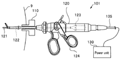
- a surgical system 101 shown in FIG. 1 is disclosed in Japanese Unexamined Patent Publication No. 2009-195676.
- the surgical system 101 includes a treatment instrument 120 that is inserted into the abdominal cavity through an insertion hole 110H of the trocar 110 punctured on the body wall of the subject 9.
- the treatment instrument 120 is an ultrasonic treatment instrument, and includes a vibration transmission member (horn) 122 that transmits vibration generated by the ultrasonic vibrator 123 joined to the back mass 123A to the treatment section 121 at the tip.
- the treatment unit 121 is opened and closed by operating the grasping unit 124 grasped by the surgeon, and holds the affected part to be treated.
- the treatment tool 120 is connected to a cable 135 for supplying power from the power supply unit 130 to the ultrasonic transducer.
- the cable 135 interferes with the surgeon's operation and reduces operability.
- JP-A-11-128242 discloses a system that generates an AC magnetic field from a power transmission coil of a trocar and wirelessly supplies power to a power reception coil of a treatment instrument inserted in the trocar.
- the conductor disposed inside the treatment tool is induction-heated by the eddy current generated by the alternating magnetic field.
- the horn of an ultrasonic treatment instrument is heated because it is made of a high-strength metal, and the operation of the ultrasonic treatment device or the treatment unit increases due to the temperature increase or the power transmission efficiency decreases. There was a risk of becoming.
- Embodiments of the present invention are intended to provide a treatment instrument with a stable operation of receiving an AC magnetic field wirelessly and a surgical system with a stable operation of receiving an AC magnetic field wirelessly.
- a treatment instrument includes a solenoid-shaped power receiving coil that inductively couples with a power transmission coil that generates an alternating magnetic field and wirelessly receives power, a treatment unit that performs a treatment with the power received by the power receiving coil, and the power receiving A conductor inserted through the inside of the coil, and a magnetic flux concentrating member made of a soft magnetic material disposed inside the power receiving coil.
- the surgical system of another embodiment includes a trocar having a power transmission coil that generates a solenoid-shaped AC magnetic field wound around an insertion hole, and inductively couples with the power transmission coil when inserted into the insertion port to generate electric power.
- a solenoid-shaped power receiving coil that wirelessly receives power, a treatment unit that performs a treatment using power received by the power receiving coil, a conductor that passes through the power receiving coil, and a power coil disposed inside the power receiving coil.
- a treatment instrument inserted into the insertion hole having a magnetic flux concentrating member made of a soft magnetic material, and a power supply unit that outputs drive power to the power transmission coil.
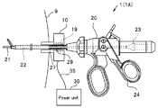
- the surgical system 1 and the ultrasonic treatment instrument (hereinafter also referred to as “treatment instrument”) 20 according to the first embodiment will be described with reference to FIGS. 2 to 5.
- the surgical operation system 1 includes a trocar 10, a power unit 30, and a treatment tool 20.
- the surgical treatment tool 20 is inserted into the body of the subject 9, for example, into the abdominal cavity, through the insertion hole 10H of the trocar 10 punctured on the body wall of the subject 9.
- an endoscope or the like is also inserted into the body of the subject 9 via another trocar, but the description thereof is omitted.
- the power supply unit 30 outputs a relatively high power, high frequency driving power of, for example, 10 W to 100 W.
- the trocar 10 has a solenoid-shaped power transmission coil 19 wound around the insertion hole 10H.
- the power transmission coil 19 generates an AC magnetic field when AC drive power is supplied from the power supply unit 30.
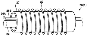
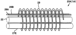
- the treatment instrument 20 includes a power receiving coil 29, an ultrasonic transducer 23, a horn 22 that is a vibration transmission member made of a conductor, a treatment portion 21, a magnetic flux concentrating member 27, an operation wire 26A, and an electrical wiring 26B. And an ultrasonic treatment device comprising: The treatment tool 20 is inserted into the body of the subject 9 through the insertion hole 10H of the trocar 10.
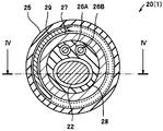
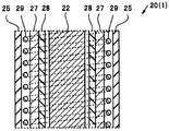
- the horn 22, the operation wire 26A, and the electrical wiring 26B are rod-like and wire-like components inserted through the lumens of the multi-lumen tube 28, respectively. Further, the outer periphery of the power receiving coil 29 is covered with an outer tube 25 made of a highly biocompatible resin.
- the power receiving coil 29 wound around the outer periphery of the multi-lumen tube 28 has a solenoid shape and the long axis direction is the longitudinal direction of the treatment instrument 20.
- the power receiving coil 29 is inserted concentrically into the power transmitting coil 19, and the power receiving coil 29 is inductively coupled to the power transmitting coil 19 to receive power wirelessly.
- the power transmission coil 19 constitutes a power transmission side LC series resonance circuit including a power transmission circuit (not shown) having a power transmission capacitor, and generates an AC magnetic field having a predetermined resonance frequency FR1.
- the power receiving coil 29 constitutes a power receiving side LC series resonance circuit including a power receiving circuit (not shown) having a power receiving capacitor, and efficiently receives an AC magnetic field having a predetermined resonance frequency FR2.
- the resonance frequency FR1 of the power transmission side LC series resonance circuit and the resonance frequency FR2 of the power reception side LC series resonance circuit are substantially the same.
- wireless power transmission / reception is efficiently performed by the magnetic field resonance phenomenon.
- the resonance frequencies FR1 and FR2 are appropriately selected within a range of 10 kHz to 20 MHz, for example.
- the grasping portion 24 of the treatment instrument 20 is grasped and operated by the operator.
- the ultrasonic vibrator 23 composed of the laminated piezoelectric element vibrates ultrasonically when the driving power received by the power receiving coil 29 is applied.
- the base end portion of the ultrasonic transducer 23 is mechanically coupled to a back mass 23A made of metal.
- the horn 22 has a rod shape and transmits the vibration of the ultrasonic vibrator 23 to the treatment unit 21. That is, the horn 22 has a proximal end portion mechanically coupled to the ultrasonic transducer 23 and a distal end portion mechanically coupled to the treatment portion 21.
- the horn 22 is made of a high-strength metal such as a titanium alloy such as 64 titanium alloy or pure titanium in order to efficiently transmit vibration.
- the treatment unit 21 includes a vibration unit that vibrates ultrasonically and a holding unit that is paired with the vibration unit.
- a vibration unit that vibrates ultrasonically
- a holding unit that is paired with the vibration unit.
- the cable 35 from the power supply unit 30 is connected to the trocar 10. Since the ultrasonic transducer 23 is driven by the power received wirelessly by the power receiving coil 29, the treatment instrument 20 does not require a power supply cable and has good operability.
- the hollow cylindrical magnetic flux concentrating member 27 disposed in the power receiving coil 29 is made of a soft magnetic material having a high magnetic permeability ⁇ , such as soft ferrite, permalloy, or an amorphous alloy.
- the soft magnetic material is made of a material having a drive signal frequency, that is, a magnetic permeability ⁇ at the resonance frequency FR1 of 100 or more, preferably 1000 or more. If the magnetic permeability ⁇ is not less than the above range, the magnetic flux concentration effect can be sufficiently obtained in the cross-sectional area where the magnetic flux concentration member 27 can be disposed inside the treatment instrument 20.
- the upper limit of the magnetic permeability ⁇ is not particularly limited, but technically, for example, is 100,000.
- the AC magnetic field generated by the power transmission coil 19 is In the power receiving coil 29, the magnetic flux is concentrated on the magnetic flux concentrating member 27, so that a strong magnetic field is not applied to the horn 22 or the like.
- the horn 22, the operation wire 26 ⁇ / b> A, and the electric wiring 26 ⁇ / b> B are made of a conductor and pass through the inside of the power receiving coil 29, but are not induction-heated by an AC magnetic field. There is no risk of temperature rise due to generation. Moreover, the surgical system 1 does not have a possibility that the transmission efficiency of electric power will fall. Therefore, the operation of the treatment tool 20 and the surgical system 1 is stable.
- the magnetic flux concentrating member 27 shown in FIG. 5 and the like is inserted through the inside of the power receiving coil 29, the heat generation preventing effect can be obtained even if the length of the magnetic flux concentrating member 27 is shorter than the length of the power receiving coil 29.
- the ultrasonic treatment instrument has been described as the treatment instrument 20, the same effect can be obtained even with various treatment instruments in which a conductor is disposed inside the power receiving coil 29, such as an electric knife or a high-frequency forceps. It is done.
- a conductive member other than the horn 22, the operation wire 26 ⁇ / b> A, and the electric wiring 26 ⁇ / b> B may be disposed inside the power receiving coil 29, and a conductive member that is not inserted through the power receiving coil 29 is disposed. May be.
- modified examples 1 to 4 of the treatment instrument of the first embodiment will be described with reference to FIGS. 6A to 6D.
- the treatment tool and the surgical system of Modifications 1 to 4 are different from the treatment tool 20 and the surgical system 1 of the first embodiment only in the form of the magnetic flux concentrating member, and the other configurations are the same. For this reason, only the magnetic flux concentration member will be described.
- the magnetic flux concentrating efficiency of the magnetic flux concentrating member that is, the magnetic permeability ⁇ decreases as the frequency of the alternating magnetic field increases.
- the frequency of the alternating magnetic field generated by the power transmission coil 19 can be relatively high, for example, 10 kHz to 20 MHz.
- the loss reduction can be suppressed by increasing the specific resistance of the soft magnetic material of the magnetic flux concentrating member.
- Modifications 1 to 4 described below are more preferable.
- the conductive soft magnetic material is divided by the insulating layer made of resin or the like.
- the treatment tool and the surgical system of Modifications 1 to 4 have the effects of the treatment tool 20 and the surgical system 1, and the operation is similarly stable even if the volume of the magnetic flux concentrating member is small.
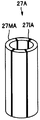
- the magnetic flux concentrating member 27A of Modification 1 shown in FIG. 6A includes a plurality of members 27MA that are divided into four along the circumference in the major axis direction and an insulating material 27IA that insulates the members 27MA.
- the magnetic flux concentrating member 27A has a split surface (cut surface) in a plane parallel to the major axis direction, and the split surface is insulated. A predetermined effect can be obtained if there is a cut surface in at least one place.
- the upper limit of the number of divisions is not particularly limited. For example, if the number is 10 or more, there is no significant difference in effect.
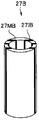
- the magnetic flux concentrating member 27B of Modification 2 shown in FIG. 6B includes a plurality of members 27MB that are divided into four in the major axis direction in parallel to the circumference, and an insulating material 27IB that insulates the members 27MB.
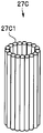
- the magnetic flux concentrating member 27C of Modification 3 shown in FIG. 6C is composed of a plurality of rod-shaped (columnar) members 27C whose outer periphery is covered with an insulating material.
- the magnetic flux concentrating member 27C may have a prismatic shape or the like.
- a magnetic flux concentrating member 27D of Modification 4 shown in FIG. 6D has a thin ribbon 27MD made of a soft magnetic material wound around an insulating layer 27ID.
- the magnetic flux concentrating member 27D has a spiral cross section perpendicular to the long axis, and the contact portion of the laminated ribbon 27MD is insulated.
- the ribbon 27MD for example, an amorphous ribbon manufactured by a high-speed quenching method can be used.
- the thin ribbon 27MD can concentrate the magnetic flux efficiently because the permeability ⁇ is not easily lowered by the skin effect.
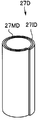
- the magnetic flux concentrating member 27E has a rod shape. Since the magnetic flux concentrating member 27E is made of the same material as that of the magnetic flux concentrating member 27, the same effect as that of the magnetic flux concentrating member 27 can be obtained even in a rod shape. Further, since the rod-shaped magnetic flux concentrating member 27E can be produced by, for example, extrusion molding, compared to the hollow cylindrical magnetic flux concentrating member 27, it is easy to produce and has a high degree of freedom in arrangement.
- the cross-sectional shape of the magnetic flux concentrating member 27E may be rectangular or polygonal.
- the magnetic flux concentrating member 27E may be disposed in a lumen having a circular cross section of a multi-lumen tube (see FIG. 4 and the like).
- the magnetic flux concentrating member 27E is eccentric from the central axis of the power receiving coil 29 in order to increase the degree of freedom of arrangement of other members. Further, a thick component can be inserted into the power receiving coil 29.
- the treatment instrument 20A includes the single magnetic flux concentrating member 27E, a plurality of rod-shaped magnetic flux concentrating members may be disposed inside the power receiving coil 29.
- modified examples 1 to 4 of the treatment tool of the second embodiment will be described with reference to FIGS. 8A to 8D.
- the treatment tool and the surgical system of Modifications 1 to 4 are different from the treatment tool 20A and the surgical system 1A of the second embodiment only in the form of the magnetic flux concentrating member, and the other configurations are the same. For this reason, only the magnetic flux concentration member will be described.
- the conductive soft magnetic material is divided by the insulating layer.
- the treatment tool and the surgical system of Modifications 1 to 4 have the effects of the treatment tool 20A and the surgical system 1A, and even if the volume of the magnetic flux concentrating member is small, the operation is similarly stable.
- a magnetic flux concentrating member 27E1 of Modification 1 shown in FIG. 8A includes a plurality of members 27ME1 that are divided into four in the major axis direction in parallel to the circumference, and an insulating material 27IE1 that insulates between the members 27ME1.
- a magnetic flux concentrating member 27E2 of Modification 2 shown in FIG. 8B is composed of a plurality of cylindrical members 27ME2 whose outer periphery is coated with an insulating material.
- covered with the insulating material may be arrange
- a magnetic flux concentrating member 27E3 of Modification 3 shown in FIG. 8C is composed of a plurality of prismatic members 27ME3 each insulated by an insulating material 27IE3.
- the prismatic member 27ME3 can be arranged more densely than the cylindrical member 27ME2.
- a magnetic flux concentrating member 27E4 of Modification 4 shown in FIG. 8D has a ribbon 27ME4 made of a soft magnetic material wound around an insulating layer 27IE4.
- the surgical system 1B includes an endoscope 40 and a treatment tool 20B that are inserted into the body of a subject.
- the endoscope 40 includes an elongated insertion portion 44 in which an imaging element 41 is disposed at a distal end portion 45, a gripping portion 43 disposed on the proximal end side of the insertion portion 44, and a processor extending from the gripping portion 43. And a universal cord (not shown) connected to.
- a channel 42 passes through the inside of the insertion portion 44 from the grip portion 43 to the distal end portion 45.
- the treatment tool 20B is inserted into the channel 42 from the grip portion 43.
- a solenoid-shaped power transmission coil 19B is wound around the channel of the endoscope 40.
- the power transmission coil 19B is connected to a power supply unit (not shown).
- the treatment instrument 20B includes a power receiving coil 29B that is concentrically arranged with the power transmitting coil 19B and is inductively coupled when inserted into the channel 42. Treatment is performed in a treatment section (not shown) at the distal end by the power received wirelessly by the power receiving coil 29B. And the electric wiring 22F etc. which use copper as a core wire are inserted in the inside of the receiving coil 29B.
- a magnetic flux concentrating member 27F made of a soft magnetic material is disposed inside the power receiving coil 29B, similar to the magnetic flux concentrating members 27 to 27E. For this reason, there is no possibility that the electric wiring 22F made of a conductor is heated by induction heating. In addition, the endoscope system 1B and the treatment tool 20B do not have a possibility of reducing the power transmission efficiency. For this reason, operation
- the magnetic flux concentration member 27F has flexibility.
- the magnetic flux concentrating member 27F it is preferable to use a composite magnetic material in which soft magnetic particles are dispersed in a flexible resin, or a thin wire (wire) magnetic material.
Abstract
The treatment tool (20) is equipped with: a solenoid power-receiving coil (29) for inductively coupling to a power-transmitting coil (19), which generates an alternating magnetic field, and wirelessly receiving power; a treatment part (21) for performing treatment using the power received by the power-receiving coil (29); a horn (22), which is inserted inside the power-receiving coil (29); and a magnetic flux-concentrating member (27), which is disposed inside the power-receiving coil (29) and is obtained from a soft magnetic substance.
Description
本発明は、交流磁界を介して電力をワイヤレスで受電する処置具、および前記処置具を具備する手術システムに関する。
The present invention relates to a treatment instrument that wirelessly receives electric power via an alternating magnetic field, and a surgical system including the treatment instrument.
内視鏡手術は低侵襲であることから広く行われている。例えば、図1に示す手術システム101が日本国特開2009-195676号公報に開示されている。手術システム101は、被検体9の体壁に穿刺されたトロッカー110の挿入孔110Hを介して腹腔内に挿入される処置具120を具備する。
Endoscopic surgery is widely performed because it is minimally invasive. For example, a surgical system 101 shown in FIG. 1 is disclosed in Japanese Unexamined Patent Publication No. 2009-195676. The surgical system 101 includes a treatment instrument 120 that is inserted into the abdominal cavity through an insertion hole 110H of the trocar 110 punctured on the body wall of the subject 9.
処置具120は、超音波処置具であり、バックマス123Aと接合された超音波振動子123の発生する振動を先端の処置部121に伝達する振動伝達部材(ホーン)122を有する。処置部121は術者が把持する把持部124の操作により開閉し、処置する患部を挟持する。
The treatment instrument 120 is an ultrasonic treatment instrument, and includes a vibration transmission member (horn) 122 that transmits vibration generated by the ultrasonic vibrator 123 joined to the back mass 123A to the treatment section 121 at the tip. The treatment unit 121 is opened and closed by operating the grasping unit 124 grasped by the surgeon, and holds the affected part to be treated.
処置具120には、電源ユニット130からの電力を超音波振動子に供給するためのケーブル135が接続されている。しかし、ケーブル135は、術者が手術するときの邪魔になり操作性を低下させている。
The treatment tool 120 is connected to a cable 135 for supplying power from the power supply unit 130 to the ultrasonic transducer. However, the cable 135 interferes with the surgeon's operation and reduces operability.
特開平11-128242号公報には、トロッカーの送電コイルから交流磁界を発生し、トロッカーに挿入された処置具の受電コイルに電力をワイヤレスで供給するシステムが開示されている。
JP-A-11-128242 discloses a system that generates an AC magnetic field from a power transmission coil of a trocar and wirelessly supplies power to a power reception coil of a treatment instrument inserted in the trocar.
しかし、交流磁界により電力をワイヤレス送電する手術システムでは、処置具の内部に配設されている導電体が交流磁界による発生する渦電流で誘導加熱されてしまう。例えば、超音波処置具のホーンは、高強度の金属からなるため加熱されて、超音波振動子や処置部の温度が上昇したり、電力の伝送効率が低下したりして動作が不安定になるおそれがあった。
However, in a surgical system that wirelessly transmits power using an alternating magnetic field, the conductor disposed inside the treatment tool is induction-heated by the eddy current generated by the alternating magnetic field. For example, the horn of an ultrasonic treatment instrument is heated because it is made of a high-strength metal, and the operation of the ultrasonic treatment device or the treatment unit increases due to the temperature increase or the power transmission efficiency decreases. There was a risk of becoming.
本発明の実施形態は、交流磁界をワイヤレスで受電する動作が安定した処置具、および交流磁界をワイヤレスで受電する動作が安定した手術システムを提供することを目的とする。
Embodiments of the present invention are intended to provide a treatment instrument with a stable operation of receiving an AC magnetic field wirelessly and a surgical system with a stable operation of receiving an AC magnetic field wirelessly.
本発明の実施形態の処置具は、交流磁界を発生する送電コイルと誘導結合し電力を無線受電するソレノイド形状の受電コイルと、前記受電コイルが受電する電力により処置を行う処置部と、前記受電コイルの内部を挿通している導電体と、前記受電コイルの内部に配設されている軟磁性体からなる磁束集中部材と、を具備する。
A treatment instrument according to an embodiment of the present invention includes a solenoid-shaped power receiving coil that inductively couples with a power transmission coil that generates an alternating magnetic field and wirelessly receives power, a treatment unit that performs a treatment with the power received by the power receiving coil, and the power receiving A conductor inserted through the inside of the coil, and a magnetic flux concentrating member made of a soft magnetic material disposed inside the power receiving coil.
また、別の実施形態の手術システムは、挿入孔を巻回しているソレノイド形状の交流磁界を発生する送電コイルを有するトロッカーと、前記挿入口に挿入されると前記送電コイルと誘導結合し電力を無線受電するソレノイド形状の受電コイルと、前記受電コイルが受電する電力により処置を行う処置部と、前記受電コイルの内部を挿通している導電体と、前記受電コイルの内部に配設されている軟磁性体からなる磁束集中部材と、を有する前記挿入孔に挿入される処置具と、前記送電コイルに駆動電力を出力する電源ユニットと、を具備する。
Further, the surgical system of another embodiment includes a trocar having a power transmission coil that generates a solenoid-shaped AC magnetic field wound around an insertion hole, and inductively couples with the power transmission coil when inserted into the insertion port to generate electric power. A solenoid-shaped power receiving coil that wirelessly receives power, a treatment unit that performs a treatment using power received by the power receiving coil, a conductor that passes through the power receiving coil, and a power coil disposed inside the power receiving coil. A treatment instrument inserted into the insertion hole having a magnetic flux concentrating member made of a soft magnetic material, and a power supply unit that outputs drive power to the power transmission coil.
本発明の実施形態によれば、交流磁界をワイヤレスで受電する動作が安定した処置具、および交流磁界をワイヤレスで受電する動作が安定した手術システムを提供できる。
According to the embodiment of the present invention, it is possible to provide a treatment instrument having a stable operation of receiving an AC magnetic field wirelessly and a surgical system having a stable operation of receiving an AC magnetic field wirelessly.
<第1実施形態>
最初に、図2~図5を用いて、第1実施形態の手術システム1、および超音波処置具(以下「処置具」ともいう)20について説明する。図2に示すように、手術システム1は、トロッカー10と、電源ユニット(Power unit)30と、処置具20と、を具備する。手術用の処置具20は被検体9の体壁に穿刺されたトロッカー10の挿入孔10Hを介して被検体9の体内、例えば腹腔内に挿入される。なお、手術システム1では、内視鏡等も別のトロッカーを介して被検体9の体内に挿入されるが、その説明等は省略する。 <First Embodiment>
First, thesurgical system 1 and the ultrasonic treatment instrument (hereinafter also referred to as “treatment instrument”) 20 according to the first embodiment will be described with reference to FIGS. 2 to 5. As shown in FIG. 2, the surgical operation system 1 includes a trocar 10, a power unit 30, and a treatment tool 20. The surgical treatment tool 20 is inserted into the body of the subject 9, for example, into the abdominal cavity, through the insertion hole 10H of the trocar 10 punctured on the body wall of the subject 9. In the surgical system 1, an endoscope or the like is also inserted into the body of the subject 9 via another trocar, but the description thereof is omitted.
最初に、図2~図5を用いて、第1実施形態の手術システム1、および超音波処置具(以下「処置具」ともいう)20について説明する。図2に示すように、手術システム1は、トロッカー10と、電源ユニット(Power unit)30と、処置具20と、を具備する。手術用の処置具20は被検体9の体壁に穿刺されたトロッカー10の挿入孔10Hを介して被検体9の体内、例えば腹腔内に挿入される。なお、手術システム1では、内視鏡等も別のトロッカーを介して被検体9の体内に挿入されるが、その説明等は省略する。 <First Embodiment>
First, the
電源ユニット30は、例えば10W~100Wの比較的大電力の高周波の駆動電力を出力する。トロッカー10は、挿入孔10Hを巻回しているソレノイド形状の送電コイル19を有する。送電コイル19は電源ユニット30から交流の駆動電力が供給されると交流磁界を発生する。
The power supply unit 30 outputs a relatively high power, high frequency driving power of, for example, 10 W to 100 W. The trocar 10 has a solenoid-shaped power transmission coil 19 wound around the insertion hole 10H. The power transmission coil 19 generates an AC magnetic field when AC drive power is supplied from the power supply unit 30.
処置具20は、受電コイル29と、超音波振動子23と、導電体からなる振動伝達部材であるホーン22と、処置部21と、磁束集中部材27と、操作ワイヤ26Aと、電気配線26Bと、を具備する超音波処置具である。処置具20は、トロッカー10の挿入孔10Hを介して被検体9の体内に挿入される。
The treatment instrument 20 includes a power receiving coil 29, an ultrasonic transducer 23, a horn 22 that is a vibration transmission member made of a conductor, a treatment portion 21, a magnetic flux concentrating member 27, an operation wire 26A, and an electrical wiring 26B. And an ultrasonic treatment device comprising: The treatment tool 20 is inserted into the body of the subject 9 through the insertion hole 10H of the trocar 10.
図3および図4に示すように、ホーン22と操作ワイヤ26Aと電気配線26Bとは、それぞれマルチルーメンチューブ28の各ルーメン内を挿通している棒状、ワイヤ状の構成要素である。また、受電コイル29の外周は生体適合性の高い樹脂からなる外装チューブ25で覆われている。
As shown in FIGS. 3 and 4, the horn 22, the operation wire 26A, and the electrical wiring 26B are rod-like and wire-like components inserted through the lumens of the multi-lumen tube 28, respectively. Further, the outer periphery of the power receiving coil 29 is covered with an outer tube 25 made of a highly biocompatible resin.
図5等に示すように、マルチルーメンチューブ28の外周に巻回された受電コイル29はソレノイド形状で長軸方向が処置具20の長手方向である。処置具20が挿入孔10Hに挿入されると、受電コイル29は送電コイル19の内部に同心円状に挿入された状態となり、受電コイル29は送電コイル19と誘導結合し、電力を無線受電する。
As shown in FIG. 5 and the like, the power receiving coil 29 wound around the outer periphery of the multi-lumen tube 28 has a solenoid shape and the long axis direction is the longitudinal direction of the treatment instrument 20. When the treatment instrument 20 is inserted into the insertion hole 10H, the power receiving coil 29 is inserted concentrically into the power transmitting coil 19, and the power receiving coil 29 is inductively coupled to the power transmitting coil 19 to receive power wirelessly.
送電コイル19は、送電コンデンサを有する送電回路(不図示)を含む送電側LC直列共振回路を構成しており、所定の共振周波数FR1の交流磁界を発生する。また、受電コイル29は、受電コンデンサを有する受電回路(不図示)を含む受電側LC直列共振回路を構成しており、所定の共振周波数FR2の交流磁界を効率良く受電する。
The power transmission coil 19 constitutes a power transmission side LC series resonance circuit including a power transmission circuit (not shown) having a power transmission capacitor, and generates an AC magnetic field having a predetermined resonance frequency FR1. The power receiving coil 29 constitutes a power receiving side LC series resonance circuit including a power receiving circuit (not shown) having a power receiving capacitor, and efficiently receives an AC magnetic field having a predetermined resonance frequency FR2.
送電側LC直列共振回路の共振周波数FR1と受電側LC直列共振回路の共振周波数FR2とは、略同じであり、手術システム1では、磁界共鳴現象により、効率的に電力の無線送受電が行われる。なお、共振周波数FR1、FR2は、例えば、10kHz~20MHzの範囲で適宜、選択される。
The resonance frequency FR1 of the power transmission side LC series resonance circuit and the resonance frequency FR2 of the power reception side LC series resonance circuit are substantially the same. In the surgical system 1, wireless power transmission / reception is efficiently performed by the magnetic field resonance phenomenon. . Note that the resonance frequencies FR1 and FR2 are appropriately selected within a range of 10 kHz to 20 MHz, for example.
処置具20の把持部24は術者が把持し操作を行う。積層型圧電体素子からなる超音波振動子23は、受電コイル29が受電した駆動電力が印加されると超音波振動する。超音波振動子23の基端部は金属からなるバックマス23Aと機械的に結合している。
The grasping portion 24 of the treatment instrument 20 is grasped and operated by the operator. The ultrasonic vibrator 23 composed of the laminated piezoelectric element vibrates ultrasonically when the driving power received by the power receiving coil 29 is applied. The base end portion of the ultrasonic transducer 23 is mechanically coupled to a back mass 23A made of metal.
ホーン22は、棒状で、超音波振動子23の振動を処置部21に伝達する。すなわち、ホーン22は基端部が超音波振動子23と機械的に結合しており、先端部が処置部21と機械的に結合している。ホーン22は、振動を効率良く伝達するために、64チタン合金等のチタン合金、又は純チタン等の高強度の金属で構成されている。
The horn 22 has a rod shape and transmits the vibration of the ultrasonic vibrator 23 to the treatment unit 21. That is, the horn 22 has a proximal end portion mechanically coupled to the ultrasonic transducer 23 and a distal end portion mechanically coupled to the treatment portion 21. The horn 22 is made of a high-strength metal such as a titanium alloy such as 64 titanium alloy or pure titanium in order to efficiently transmit vibration.
処置部21は超音波振動する振動部と振動部と対になる保持部とからなる。把持部24の操作が先端処置部開閉用の操作ワイヤ26Aを介して処置部21に伝えられると、処置対象の患部が振動部と保持部との間に挟持される。挟持した状態で、振動部が振動すると患部に超音波振動が印加されて、処置が行われる。
The treatment unit 21 includes a vibration unit that vibrates ultrasonically and a holding unit that is paired with the vibration unit. When the operation of the gripping portion 24 is transmitted to the treatment portion 21 via the distal treatment portion opening / closing operation wire 26A, the affected portion to be treated is sandwiched between the vibration portion and the holding portion. When the vibration part vibrates in the sandwiched state, ultrasonic vibration is applied to the affected part and treatment is performed.
手術システム1では、電源ユニット30からのケーブル35はトロッカー10と接続されている。処置具20は、受電コイル29が無線受電した電力により超音波振動子23が駆動されるため、電力供給のためのケーブルが不要であり、操作性がよい。
In the surgical system 1, the cable 35 from the power supply unit 30 is connected to the trocar 10. Since the ultrasonic transducer 23 is driven by the power received wirelessly by the power receiving coil 29, the treatment instrument 20 does not require a power supply cable and has good operability.
そして、受電コイル29の内部に配設されている中空円筒状の磁束集中部材27は透磁率μが高い軟磁性体、例えば、ソフトフェライト、パーマロイ、又はアモルファス合金等からなる。軟磁性体は駆動信号の周波数、すなわち共振周波数FR1における透磁率μが100以上、好ましくは1000以上の材料により構成されている。透磁率μが前記範囲以上であれば、磁束集中部材27が処置具20の内部に配設できる断面積において磁束集中効果が十分に得られる。なお、透磁率μの上限は特に限定されるものではないが、技術的に例えば100000である。
The hollow cylindrical magnetic flux concentrating member 27 disposed in the power receiving coil 29 is made of a soft magnetic material having a high magnetic permeability μ, such as soft ferrite, permalloy, or an amorphous alloy. The soft magnetic material is made of a material having a drive signal frequency, that is, a magnetic permeability μ at the resonance frequency FR1 of 100 or more, preferably 1000 or more. If the magnetic permeability μ is not less than the above range, the magnetic flux concentration effect can be sufficiently obtained in the cross-sectional area where the magnetic flux concentration member 27 can be disposed inside the treatment instrument 20. The upper limit of the magnetic permeability μ is not particularly limited, but technically, for example, is 100,000.
手術システム1では、処置具20がトロッカー10に挿入され、受電コイル29が送電コイル19の発生する交流磁界を受電する状態(誘導結合状態)になっても、送電コイル19が発生した交流磁界は、受電コイル29の内部では磁束集中部材27に集中するため、ホーン22等には強い磁界は印加されない。
In the surgical system 1, even when the treatment tool 20 is inserted into the trocar 10 and the power receiving coil 29 is in a state of receiving an AC magnetic field generated by the power transmission coil 19 (inductive coupling state), the AC magnetic field generated by the power transmission coil 19 is In the power receiving coil 29, the magnetic flux is concentrated on the magnetic flux concentrating member 27, so that a strong magnetic field is not applied to the horn 22 or the like.
ホーン22と操作ワイヤ26Aと電気配線26Bとは導電体からなり、受電コイル29の内部を挿通しているが、交流磁界により誘導加熱されないため、超音波振動子23や処置部21が渦電流の発生により温度が上昇するおそれがない。また、手術システム1は、電力の伝送効率が低下するおそれがない。このため、処置具20、および手術システム1は動作が安定している。
The horn 22, the operation wire 26 </ b> A, and the electric wiring 26 </ b> B are made of a conductor and pass through the inside of the power receiving coil 29, but are not induction-heated by an AC magnetic field. There is no risk of temperature rise due to generation. Moreover, the surgical system 1 does not have a possibility that the transmission efficiency of electric power will fall. Therefore, the operation of the treatment tool 20 and the surgical system 1 is stable.
なお、図5等に示した磁束集中部材27は、受電コイル29の内部を挿通しているが、磁束集中部材27の長さが受電コイル29の長さよりも短くとも発熱防止効果は得られる。
Although the magnetic flux concentrating member 27 shown in FIG. 5 and the like is inserted through the inside of the power receiving coil 29, the heat generation preventing effect can be obtained even if the length of the magnetic flux concentrating member 27 is shorter than the length of the power receiving coil 29.
また、処置具20として超音波処置具について説明したが、受電コイル29の内部に導電体が配置される各種の処置具、例えば、電気メス、又は高周波鉗子等であっても同様の効果が得られる。
Although the ultrasonic treatment instrument has been described as the treatment instrument 20, the same effect can be obtained even with various treatment instruments in which a conductor is disposed inside the power receiving coil 29, such as an electric knife or a high-frequency forceps. It is done.
また、受電コイル29の内部に、ホーン22、操作ワイヤ26A、電気配線26B以外の導電性部材が配設されていてもよく、さらに受電コイル29を挿通していない導電性部材が配設されていてもよい。
In addition, a conductive member other than the horn 22, the operation wire 26 </ b> A, and the electric wiring 26 </ b> B may be disposed inside the power receiving coil 29, and a conductive member that is not inserted through the power receiving coil 29 is disposed. May be.
<第1実施形態の変形例>
次に図6A~図6Dを用いて第1実施形態の処置具の変形例1~4について説明する。変形例1~4の処置具および手術システムは、第1実施形態の処置具20および手術システム1とは、磁束集中部材の形態が異なるだけであり、他の構成は同じである。このため、磁束集中部材についてのみ説明する。 <Modification of First Embodiment>
Next, modified examples 1 to 4 of the treatment instrument of the first embodiment will be described with reference to FIGS. 6A to 6D. The treatment tool and the surgical system ofModifications 1 to 4 are different from the treatment tool 20 and the surgical system 1 of the first embodiment only in the form of the magnetic flux concentrating member, and the other configurations are the same. For this reason, only the magnetic flux concentration member will be described.
次に図6A~図6Dを用いて第1実施形態の処置具の変形例1~4について説明する。変形例1~4の処置具および手術システムは、第1実施形態の処置具20および手術システム1とは、磁束集中部材の形態が異なるだけであり、他の構成は同じである。このため、磁束集中部材についてのみ説明する。 <Modification of First Embodiment>
Next, modified examples 1 to 4 of the treatment instrument of the first embodiment will be described with reference to FIGS. 6A to 6D. The treatment tool and the surgical system of
磁束集中部材の磁束集中効率、すなわち、透磁率μは交流磁界の周波数が高くなると低下する。手術システムでは、電力を無線送電するため、送電コイル19が発生する交流磁界の周波数は、例えば、10kHz~20MHzと比較的、高周波できるため、特に渦電流発生による損失低下の影響が出やすい。
The magnetic flux concentrating efficiency of the magnetic flux concentrating member, that is, the magnetic permeability μ decreases as the frequency of the alternating magnetic field increases. In the surgical system, since the electric power is transmitted wirelessly, the frequency of the alternating magnetic field generated by the power transmission coil 19 can be relatively high, for example, 10 kHz to 20 MHz.
磁束集中部材の軟磁性材料の比抵抗を高くすることで、損失低下を抑制できるが、コスト等を考慮すると、以下に説明する変形例1~4が、より好ましい。
The loss reduction can be suppressed by increasing the specific resistance of the soft magnetic material of the magnetic flux concentrating member. However, in consideration of cost and the like, Modifications 1 to 4 described below are more preferable.
すなわち、変形例1~4の磁束集中部材は、いずれも導電性の軟磁性体が樹脂等からなる絶縁層により分割されている。このため、変形例1~4の処置具および手術システムは、処置具20および手術システム1の効果を有し、さらに磁束集中部材の体積が小さくても、同じように動作が安定している。
That is, in each of the magnetic flux concentrating members of Modifications 1 to 4, the conductive soft magnetic material is divided by the insulating layer made of resin or the like. For this reason, the treatment tool and the surgical system of Modifications 1 to 4 have the effects of the treatment tool 20 and the surgical system 1, and the operation is similarly stable even if the volume of the magnetic flux concentrating member is small.
図6Aに示す変形例1の磁束集中部材27Aは、長軸方向に円周に沿って4分割されている複数の部材27MAと、部材27MAの間を絶縁している絶縁材料27IAとからなる。言い換えれば、磁束集中部材27Aは、長軸方向と平行な面に分割面(切断面)を有しており、分割面は絶縁されている。なお、少なくとも1箇所に切断面があれば所定の効果が得られる。分割数の上限は特に制限ないが、例えば10以上であれば効果に顕著な差はない。
The magnetic flux concentrating member 27A of Modification 1 shown in FIG. 6A includes a plurality of members 27MA that are divided into four along the circumference in the major axis direction and an insulating material 27IA that insulates the members 27MA. In other words, the magnetic flux concentrating member 27A has a split surface (cut surface) in a plane parallel to the major axis direction, and the split surface is insulated. A predetermined effect can be obtained if there is a cut surface in at least one place. The upper limit of the number of divisions is not particularly limited. For example, if the number is 10 or more, there is no significant difference in effect.
図6Bに示す変形例2の磁束集中部材27Bは、長軸方向に円周に平行に4分割されている複数の部材27MBと、部材27MBの間を絶縁している絶縁材料27IBとからなる。
The magnetic flux concentrating member 27B of Modification 2 shown in FIG. 6B includes a plurality of members 27MB that are divided into four in the major axis direction in parallel to the circumference, and an insulating material 27IB that insulates the members 27MB.
図6Cに示す変形例3の磁束集中部材27Cは、外周が絶縁材料で被覆された複数の棒状(円柱状)の部材27Cからなる。磁束集中部材27Cは、角柱状等であってもよい。
The magnetic flux concentrating member 27C of Modification 3 shown in FIG. 6C is composed of a plurality of rod-shaped (columnar) members 27C whose outer periphery is covered with an insulating material. The magnetic flux concentrating member 27C may have a prismatic shape or the like.
図6Dに示す変形例4の磁束集中部材27Dは、軟磁性体からなる薄帯27MDが絶縁層27IDを介して巻回されている。言い換えれば、磁束集中部材27Dは、長軸と垂直な断面が渦巻き形状で、積層された薄帯27MDの接触部分が絶縁されている。薄帯27MDは、例えば、高速急冷法で作製されたアモルファス薄帯等を用いることができる。
A magnetic flux concentrating member 27D of Modification 4 shown in FIG. 6D has a thin ribbon 27MD made of a soft magnetic material wound around an insulating layer 27ID. In other words, the magnetic flux concentrating member 27D has a spiral cross section perpendicular to the long axis, and the contact portion of the laminated ribbon 27MD is insulated. As the ribbon 27MD, for example, an amorphous ribbon manufactured by a high-speed quenching method can be used.
薄帯27MDは表皮効果により透磁率μが低下しにくいため、効率的に磁束を集中できる。
The thin ribbon 27MD can concentrate the magnetic flux efficiently because the permeability μ is not easily lowered by the skin effect.
<第2実施形態>
次に、第2実施形態の手術システム1Aおよび処置具20Aについて説明する。手術システム1A等は、手術システム1等と類似しているので同じ構成要素には同じ符号を付し説明は省略する。 Second Embodiment
Next, thesurgical operation system 1A and the treatment tool 20A according to the second embodiment will be described. Since the surgical system 1A and the like are similar to the surgical system 1 and the like, the same components are denoted by the same reference numerals and description thereof is omitted.
次に、第2実施形態の手術システム1Aおよび処置具20Aについて説明する。手術システム1A等は、手術システム1等と類似しているので同じ構成要素には同じ符号を付し説明は省略する。 Second Embodiment
Next, the
図7に示すように、手術システム1Aの処置具20Aでは、磁束集中部材27Eは棒状である。磁束集中部材27Eは、磁束集中部材27と同様の材料からなるため、棒状であっても磁束集中部材27と同様の効果が得られる。また、棒状の磁束集中部材27Eは、中空円筒状の磁束集中部材27よりも、例えば押し出し成型で作製できるため、作製が容易で、かつ、配置の自由度が高い。
As shown in FIG. 7, in the treatment tool 20A of the surgical system 1A, the magnetic flux concentrating member 27E has a rod shape. Since the magnetic flux concentrating member 27E is made of the same material as that of the magnetic flux concentrating member 27, the same effect as that of the magnetic flux concentrating member 27 can be obtained even in a rod shape. Further, since the rod-shaped magnetic flux concentrating member 27E can be produced by, for example, extrusion molding, compared to the hollow cylindrical magnetic flux concentrating member 27, it is easy to produce and has a high degree of freedom in arrangement.
なお、磁束集中部材27Eの断面形状は矩形でも多角形等でもよい。例えば、磁束集中部材27Eが、マルチルーメンチューブ(図4等参照)の断面が円形のルーメンの中に配設されていてもよい。
The cross-sectional shape of the magnetic flux concentrating member 27E may be rectangular or polygonal. For example, the magnetic flux concentrating member 27E may be disposed in a lumen having a circular cross section of a multi-lumen tube (see FIG. 4 and the like).
なお、磁束集中部材27Eは中心軸が受電コイル29の中心軸から偏心していることが、他の部材の配置の自由度を上げるために、好ましい。また、受電コイル29の内部に太い構成要素を挿通できる。
In addition, it is preferable that the magnetic flux concentrating member 27E is eccentric from the central axis of the power receiving coil 29 in order to increase the degree of freedom of arrangement of other members. Further, a thick component can be inserted into the power receiving coil 29.
さらに、処置具20Aは、1本の磁束集中部材27Eを具備していたが、複数本の棒状の磁束集中部材を、受電コイル29の内部に配設してもよい。
Furthermore, although the treatment instrument 20A includes the single magnetic flux concentrating member 27E, a plurality of rod-shaped magnetic flux concentrating members may be disposed inside the power receiving coil 29.
<第2実施形態の変形例>
次に図8A~図8Dを用いて第2実施形態の処置具の変形例1~4について説明する。変形例1~4の処置具および手術システムは、第2実施形態の処置具20Aおよび手術システム1Aとは、磁束集中部材の形態が異なるだけであり、他の構成は同じである。このため、磁束集中部材についてのみ説明する。 <Modification of Second Embodiment>
Next, modified examples 1 to 4 of the treatment tool of the second embodiment will be described with reference to FIGS. 8A to 8D. The treatment tool and the surgical system ofModifications 1 to 4 are different from the treatment tool 20A and the surgical system 1A of the second embodiment only in the form of the magnetic flux concentrating member, and the other configurations are the same. For this reason, only the magnetic flux concentration member will be described.
次に図8A~図8Dを用いて第2実施形態の処置具の変形例1~4について説明する。変形例1~4の処置具および手術システムは、第2実施形態の処置具20Aおよび手術システム1Aとは、磁束集中部材の形態が異なるだけであり、他の構成は同じである。このため、磁束集中部材についてのみ説明する。 <Modification of Second Embodiment>
Next, modified examples 1 to 4 of the treatment tool of the second embodiment will be described with reference to FIGS. 8A to 8D. The treatment tool and the surgical system of
変形例1~4の磁束集中部材は、第1実施形態の処置具20の磁束集中部材と同様に、いずれも導電性の軟磁性体が絶縁層により分割されている。このため、変形例1~4の処置具および手術システムは、処置具20Aおよび手術システム1Aの効果を有し、さらに磁束集中部材の体積が小さくても、同じように動作が安定している。
As for the magnetic flux concentrating members of the first to fourth modified examples, like the magnetic flux concentrating member of the treatment instrument 20 of the first embodiment, the conductive soft magnetic material is divided by the insulating layer. For this reason, the treatment tool and the surgical system of Modifications 1 to 4 have the effects of the treatment tool 20A and the surgical system 1A, and even if the volume of the magnetic flux concentrating member is small, the operation is similarly stable.
図8Aに示す変形例1の磁束集中部材27E1は、長軸方向に円周に平行に4分割されている複数の部材27ME1と、部材27ME1の間を絶縁している絶縁材料27IE1とからなる。
A magnetic flux concentrating member 27E1 of Modification 1 shown in FIG. 8A includes a plurality of members 27ME1 that are divided into four in the major axis direction in parallel to the circumference, and an insulating material 27IE1 that insulates between the members 27ME1.
図8Bに示す変形例2の磁束集中部材27E2は、外周が絶縁材料で被覆された複数の円柱状の部材27ME2からなる。なお、絶縁材料で被覆されていない円柱状軟磁性体が、マルチルーメンチューブの異なるルーメンに配設されていてもよい。
A magnetic flux concentrating member 27E2 of Modification 2 shown in FIG. 8B is composed of a plurality of cylindrical members 27ME2 whose outer periphery is coated with an insulating material. In addition, the cylindrical soft magnetic body which is not coat | covered with the insulating material may be arrange | positioned by the different lumen | rumen of a multi-lumen tube.
図8Cに示す変形例3の磁束集中部材27E3は、それぞれが絶縁材料27IE3で絶縁された複数の角柱状の部材27ME3からなる。角柱状の部材27ME3は、円柱状の部材27ME2よりも密に配設することができる。
A magnetic flux concentrating member 27E3 of Modification 3 shown in FIG. 8C is composed of a plurality of prismatic members 27ME3 each insulated by an insulating material 27IE3. The prismatic member 27ME3 can be arranged more densely than the cylindrical member 27ME2.
図8Dに示す変形例4の磁束集中部材27E4は、軟磁性体からなる薄帯27ME4が絶縁層27IE4を介して巻回されている。
A magnetic flux concentrating member 27E4 of Modification 4 shown in FIG. 8D has a ribbon 27ME4 made of a soft magnetic material wound around an insulating layer 27IE4.
<第3実施形態>
次に、第3実施形態の内視鏡システム1Bおよび処置具20Bについて説明する。手術システム1B等は、手術システム1等と類似しているので同じ構成要素には同じ符号を付し説明は省略する。 <Third Embodiment>
Next, anendoscope system 1B and a treatment tool 20B according to a third embodiment will be described. Since the surgical system 1B and the like are similar to the surgical system 1 and the like, the same components are denoted by the same reference numerals and description thereof is omitted.
次に、第3実施形態の内視鏡システム1Bおよび処置具20Bについて説明する。手術システム1B等は、手術システム1等と類似しているので同じ構成要素には同じ符号を付し説明は省略する。 <Third Embodiment>
Next, an
図9に示すように、手術システム1Bは、被検体の体内に挿入される内視鏡40と処置具20Bとを有する。内視鏡40は、先端部45に撮像素子41が配設された細長い挿入部44と、挿入部44の基端部側に配設された把持部43と、把持部43から延設されプロセッサと接続されるユニバーサルコード(不図示)と、を有する。把持部43から先端部45まで挿入部44の内部をチャンネル42が挿通している。処置具20Bは、把持部43からチャンネル42に挿入される。
As shown in FIG. 9, the surgical system 1B includes an endoscope 40 and a treatment tool 20B that are inserted into the body of a subject. The endoscope 40 includes an elongated insertion portion 44 in which an imaging element 41 is disposed at a distal end portion 45, a gripping portion 43 disposed on the proximal end side of the insertion portion 44, and a processor extending from the gripping portion 43. And a universal cord (not shown) connected to. A channel 42 passes through the inside of the insertion portion 44 from the grip portion 43 to the distal end portion 45. The treatment tool 20B is inserted into the channel 42 from the grip portion 43.
内視鏡40のチャンネルには、ソレノイド形状の送電コイル19Bが巻回されている。送電コイル19Bは電源ユニット(不図示)と接続されている。
A solenoid-shaped power transmission coil 19B is wound around the channel of the endoscope 40. The power transmission coil 19B is connected to a power supply unit (not shown).
手術システム1Bでは、処置具20Bは、チャンネル42に挿入されると送電コイル19Bと同心円状に配置され誘導結合する受電コイル29Bを有する。受電コイル29Bが無線受電した電力により、先端の処置部(不図示)において処置が行われる。そして、受電コイル29Bの内部には、銅を芯線とする電気配線22F等が挿通している。
In the surgical system 1B, the treatment instrument 20B includes a power receiving coil 29B that is concentrically arranged with the power transmitting coil 19B and is inductively coupled when inserted into the channel 42. Treatment is performed in a treatment section (not shown) at the distal end by the power received wirelessly by the power receiving coil 29B. And the electric wiring 22F etc. which use copper as a core wire are inserted in the inside of the receiving coil 29B.
処置具20Bは、受電コイル29Bの内部に、磁束集中部材27~27Eと同じような、軟磁性体からなる磁束集中部材27Fが配設されている。このため、導電体からなる電気配線22Fが誘導加熱されて発熱するおそれがない。また内視鏡システム1B、および処置具20Bは、電力の伝送効率が低下するおそれがない。このため、手術システム1B、及処置具20Bは動作が安定している。
In the treatment instrument 20B, a magnetic flux concentrating member 27F made of a soft magnetic material is disposed inside the power receiving coil 29B, similar to the magnetic flux concentrating members 27 to 27E. For this reason, there is no possibility that the electric wiring 22F made of a conductor is heated by induction heating. In addition, the endoscope system 1B and the treatment tool 20B do not have a possibility of reducing the power transmission efficiency. For this reason, operation | movement of the surgery system 1B and the treatment tool 20B is stable.
なお、挿入部44の可撓性を担保するために、磁束集中部材27Fは可撓性を有することが好ましい。例えば、磁束集中部材27Fとして、軟磁性体粒子が可撓性樹脂中に分散した複合磁性体を用いたり、細線(ワイヤー)の磁性体等を用いたりすることが好ましい。
In addition, in order to ensure the flexibility of the insertion part 44, it is preferable that the magnetic flux concentration member 27F has flexibility. For example, as the magnetic flux concentrating member 27F, it is preferable to use a composite magnetic material in which soft magnetic particles are dispersed in a flexible resin, or a thin wire (wire) magnetic material.
本発明は、上述した実施の形態に限定されるものではなく、本発明の要旨を変えない範囲において、種々の変更、改変等が可能である。
The present invention is not limited to the above-described embodiments, and various changes and modifications can be made without departing from the scope of the present invention.
本出願は、2013年9月10日に日本国に出願された特願2013-187534号を優先権の基礎として出願するものであり、上記開示内容は、本願明細書、請求の範囲、図面に引用されたものとする。
This application is filed on the basis of Japanese Patent Application No. 2013-187534 filed in Japan on September 10, 2013, and the above disclosure is included in the present specification, claims, and drawings. It shall be quoted.
Claims (10)
- 交流磁界を発生する送電コイルと誘導結合し、電力を無線受電するソレノイド形状の受電コイルと、
前記受電コイルが受電する電力により処置を行う処置部と、
前記受電コイルの内部を挿通している導電体と、
前記受電コイルの内部に配設されている軟磁性体からなる磁束集中部材と、を具備することを特徴とする処置具。 A solenoid-shaped power receiving coil that is inductively coupled with a power transmitting coil that generates an alternating magnetic field and wirelessly receives power;
A treatment section for performing treatment by the power received by the power reception coil;
A conductor inserted through the interior of the power receiving coil;
And a magnetic flux concentrating member made of a soft magnetic material disposed inside the power receiving coil. - 前記磁束集中部材が、内部を前記導電体が挿通している中空円筒状であることを特徴とする請求項1に記載の処置具。 The treatment tool according to claim 1, wherein the magnetic flux concentrating member has a hollow cylindrical shape through which the conductor is inserted.
- 前記磁束集中部材が、棒状であることを特徴とする請求項1に記載の処置具。 The treatment tool according to claim 1, wherein the magnetic flux concentrating member has a rod shape.
- 前記磁束集中部材が、長軸方向に分割され互いに絶縁されている複数の部材からなることを特徴とする請求項2又は請求項3に記載の処置具。 The treatment tool according to claim 2 or 3, wherein the magnetic flux concentrating member is composed of a plurality of members that are divided in the major axis direction and insulated from each other.
- 前記磁束集中部材が、軟磁性体からなる薄帯が絶縁層を介して巻回されていることを特徴とする請求項2に記載の処置具。 The treatment tool according to claim 2, wherein the magnetic flux concentrating member is formed by winding a thin ribbon made of a soft magnetic material through an insulating layer.
- 前記磁束集中部材が、前記受電コイルを挿通していることを特徴とする請求項1から請求項5のいずれか1項に記載の処置具。 The treatment tool according to any one of claims 1 to 5, wherein the magnetic flux concentrating member is inserted through the power receiving coil.
- 前記送電コイルが、トロッカーの挿入孔に巻回されているソレノイド形状のコイルであることを特徴とする請求項6に記載の処置具。 The treatment instrument according to claim 6, wherein the power transmission coil is a solenoid-shaped coil wound around an insertion hole of a trocar.
- 前記受電コイルが受電した電力により超音波振動する振動子を具備し、
前記導電体が、前記振動伝達部材の基端部と機械的に結合された、超音波振動を伝達する棒状の金属からなる振動伝達部材であり、
前記処置部が、前記振動伝達部材の先端部と機械的に結合された、前記処置対象に超音波振動を印加することを特徴とする請求項1から請求項7のいずれか1項に記載の処置具。 Comprising a vibrator that vibrates ultrasonically by the power received by the power receiving coil;
The conductor is a vibration transmission member made of a rod-shaped metal that transmits ultrasonic vibrations, mechanically coupled to a base end portion of the vibration transmission member;
The said treatment part applies an ultrasonic vibration to the said treatment object mechanically couple | bonded with the front-end | tip part of the said vibration transmission member, The Claim 1 characterized by the above-mentioned. Treatment tool. - 前記送電コイルが、内視鏡の挿入部を挿通するチャンネルに巻回されているソレノイド形状のコイルであり、前記処置具が、前記チャンネルに挿入されることを特徴とする請求項1から請求項6のいずれか1項に記載の処置具。 The power transmission coil is a solenoid-shaped coil wound around a channel that passes through an insertion portion of an endoscope, and the treatment instrument is inserted into the channel. The treatment tool according to any one of 6.
- 挿入孔を巻回しているソレノイド形状の交流磁界を発生する送電コイルを有するトロッカーと、
前記挿入口に挿入されると前記送電コイルと誘導結合し電力を無線受電するソレノイド形状の受電コイルと、前記受電コイルが受電する電力により処置を行う処置部と、前記受電コイルの内部を挿通している導電体と、前記受電コイルの内部に配設されている軟磁性体からなる磁束集中部材と、を有する前記挿入孔に挿入される処置具と、
前記送電コイルに駆動電力を出力する電源ユニットと、を具備することを特徴とする手術システム。 A trocar having a power transmission coil that generates a solenoid-shaped AC magnetic field wound around the insertion hole;
When inserted into the insertion port, a solenoid-shaped power receiving coil that inductively couples with the power transmitting coil and wirelessly receives power, a treatment unit that performs a treatment with the power received by the power receiving coil, and the inside of the power receiving coil are inserted A treatment instrument inserted into the insertion hole, comprising: a conductor having a magnetic flux concentration member made of a soft magnetic material disposed inside the power receiving coil;
And a power supply unit that outputs driving power to the power transmission coil.
Priority Applications (3)
| Application Number | Priority Date | Filing Date | Title |
|---|---|---|---|
| CN201480049166.0A CN105530882B (en) | 2013-09-10 | 2014-02-14 | Treatment apparatus and surgery systems |
| EP14843447.5A EP3045131A4 (en) | 2013-09-10 | 2014-02-14 | Treatment tool and surgical system |
| US15/065,005 US20160183773A1 (en) | 2013-09-10 | 2016-03-09 | Treatment device and surgical system |
Applications Claiming Priority (2)
| Application Number | Priority Date | Filing Date | Title |
|---|---|---|---|
| JP2013-187534 | 2013-09-10 | ||
| JP2013187534A JP6095532B2 (en) | 2013-09-10 | 2013-09-10 | Treatment instrument and surgical system |
Related Child Applications (1)
| Application Number | Title | Priority Date | Filing Date |
|---|---|---|---|
| US15/065,005 Continuation US20160183773A1 (en) | 2013-09-10 | 2016-03-09 | Treatment device and surgical system |
Publications (1)
| Publication Number | Publication Date |
|---|---|
| WO2015037253A1 true WO2015037253A1 (en) | 2015-03-19 |
Family
ID=52665382
Family Applications (1)
| Application Number | Title | Priority Date | Filing Date |
|---|---|---|---|
| PCT/JP2014/053438 WO2015037253A1 (en) | 2013-09-10 | 2014-02-14 | Treatment tool and surgical system |
Country Status (5)
| Country | Link |
|---|---|
| US (1) | US20160183773A1 (en) |
| EP (1) | EP3045131A4 (en) |
| JP (1) | JP6095532B2 (en) |
| CN (1) | CN105530882B (en) |
| WO (1) | WO2015037253A1 (en) |
Families Citing this family (2)
| Publication number | Priority date | Publication date | Assignee | Title |
|---|---|---|---|---|
| CN107205755A (en) * | 2015-02-27 | 2017-09-26 | 奥林巴斯株式会社 | Medical feed system |
| JP6109448B2 (en) | 2015-04-21 | 2017-04-05 | オリンパス株式会社 | Energy treatment tool |
Citations (8)
| Publication number | Priority date | Publication date | Assignee | Title |
|---|---|---|---|---|
| JPH11128242A (en) | 1997-06-30 | 1999-05-18 | Ethicon Endo Surgery Inc | Inductive coupling type cordless electric surgical instrument |
| JP2000254134A (en) * | 1999-03-10 | 2000-09-19 | Olympus Optical Co Ltd | Medical instrument |
| JP2000287987A (en) * | 1999-04-01 | 2000-10-17 | Olympus Optical Co Ltd | Chargeable battery type medical treatment apparatus |
| JP2004208922A (en) * | 2002-12-27 | 2004-07-29 | Olympus Corp | Medical apparatus, medical manipulator and control process for medical apparatus |
| JP2009195676A (en) | 2008-02-22 | 2009-09-03 | Olympus Medical Systems Corp | Ultrasonic treatment apparatus |
| JP2012084894A (en) * | 2006-03-24 | 2012-04-26 | Toshiba Corp | Electronic apparatus and non-contact charger |
| JP2012164728A (en) * | 2011-02-04 | 2012-08-30 | Hitachi Metals Ltd | Coil component and power reception device and power supply device using the same |
| JP2013175621A (en) * | 2012-02-27 | 2013-09-05 | Hitachi Metals Ltd | Magnetic sheet, transmission coil component and non-contact charging apparatus |
Family Cites Families (7)
| Publication number | Priority date | Publication date | Assignee | Title |
|---|---|---|---|---|
| US6666875B1 (en) * | 1999-03-05 | 2003-12-23 | Olympus Optical Co., Ltd. | Surgical apparatus permitting recharge of battery-driven surgical instrument in noncontact state |
| DE102006019989A1 (en) * | 2006-04-26 | 2007-10-31 | Siemens Ag | Endoscopic capsule for navigating inside gastrointestinal track of patient e.g. human, magnetic unit with dipole moment that produces dipole field, where part of field with orientation anti-parallel to moment penetrates via induction coil |
| DE102006019987A1 (en) * | 2006-04-26 | 2007-10-31 | Siemens Ag | Endoscopic capsule for investigation of body openings, has induction coil with elongation along one axis, and magnetic element having magnetic dipole moment aligned perpendicular to longitudinal axis of induction coil |
| JP2008178544A (en) * | 2007-01-24 | 2008-08-07 | Olympus Corp | Wireless feeding system, capsule endoscope and capsule endoscope system |
| CN101750009A (en) * | 2009-12-31 | 2010-06-23 | 南京磁谷科技有限公司 | Magnetic-shielding eddy current sensor probe and method for reducing eddy current effect |
| JP2013038893A (en) * | 2011-08-08 | 2013-02-21 | Equos Research Co Ltd | Power transmission system |
| JP5965741B2 (en) * | 2012-06-26 | 2016-08-10 | オリンパス株式会社 | Medical wireless power supply system |
-
2013
- 2013-09-10 JP JP2013187534A patent/JP6095532B2/en not_active Expired - Fee Related
-
2014
- 2014-02-14 CN CN201480049166.0A patent/CN105530882B/en not_active Expired - Fee Related
- 2014-02-14 WO PCT/JP2014/053438 patent/WO2015037253A1/en active Application Filing
- 2014-02-14 EP EP14843447.5A patent/EP3045131A4/en not_active Withdrawn
-
2016
- 2016-03-09 US US15/065,005 patent/US20160183773A1/en not_active Abandoned
Patent Citations (8)
| Publication number | Priority date | Publication date | Assignee | Title |
|---|---|---|---|---|
| JPH11128242A (en) | 1997-06-30 | 1999-05-18 | Ethicon Endo Surgery Inc | Inductive coupling type cordless electric surgical instrument |
| JP2000254134A (en) * | 1999-03-10 | 2000-09-19 | Olympus Optical Co Ltd | Medical instrument |
| JP2000287987A (en) * | 1999-04-01 | 2000-10-17 | Olympus Optical Co Ltd | Chargeable battery type medical treatment apparatus |
| JP2004208922A (en) * | 2002-12-27 | 2004-07-29 | Olympus Corp | Medical apparatus, medical manipulator and control process for medical apparatus |
| JP2012084894A (en) * | 2006-03-24 | 2012-04-26 | Toshiba Corp | Electronic apparatus and non-contact charger |
| JP2009195676A (en) | 2008-02-22 | 2009-09-03 | Olympus Medical Systems Corp | Ultrasonic treatment apparatus |
| JP2012164728A (en) * | 2011-02-04 | 2012-08-30 | Hitachi Metals Ltd | Coil component and power reception device and power supply device using the same |
| JP2013175621A (en) * | 2012-02-27 | 2013-09-05 | Hitachi Metals Ltd | Magnetic sheet, transmission coil component and non-contact charging apparatus |
Non-Patent Citations (1)
| Title |
|---|
| See also references of EP3045131A4 |
Also Published As
| Publication number | Publication date |
|---|---|
| EP3045131A1 (en) | 2016-07-20 |
| JP6095532B2 (en) | 2017-03-15 |
| JP2015053980A (en) | 2015-03-23 |
| CN105530882A (en) | 2016-04-27 |
| US20160183773A1 (en) | 2016-06-30 |
| EP3045131A4 (en) | 2017-04-26 |
| CN105530882B (en) | 2018-03-16 |
Similar Documents
| Publication | Publication Date | Title |
|---|---|---|
| JP6329422B2 (en) | Medical instruments, insertion aids, and medical systems | |
| US10441309B2 (en) | Energy treatment instrument | |
| US20100217275A1 (en) | Device for inducing vibrations in a guidewire | |
| US20150057653A1 (en) | Medical wireless power supply system | |
| US20150366434A1 (en) | Endoscope system, endoscope and treatment tool | |
| US10016235B2 (en) | Endoscope system having first transmission and reception electrodes, second transmission and reception electrodes and electrically powered treatment device powered to perform treatment | |
| JP6095532B2 (en) | Treatment instrument and surgical system | |
| JP6049569B2 (en) | Surgical system and trocar | |
| WO2015045447A1 (en) | Ultrasonic treatment tool and surgical system | |
| JP6210848B2 (en) | Medical instruments | |
| JP2016002201A (en) | Medical instruments | |
| US20170360277A1 (en) | Medical power supply system | |
| WO2014054399A1 (en) | Medical apparatus, and wireless power supply system for medical use | |
| JP2015154842A (en) | Medical device and medical system | |
| JP2015104629A (en) | Medical appliance and medical system | |
| JP2015104628A (en) | Trocar and operation system |
Legal Events
| Date | Code | Title | Description |
|---|---|---|---|
| WWE | Wipo information: entry into national phase |
Ref document number: 201480049166.0 Country of ref document: CN |
|
| 121 | Ep: the epo has been informed by wipo that ep was designated in this application |
Ref document number: 14843447 Country of ref document: EP Kind code of ref document: A1 |
|
| REEP | Request for entry into the european phase |
Ref document number: 2014843447 Country of ref document: EP |
|
| WWE | Wipo information: entry into national phase |
Ref document number: 2014843447 Country of ref document: EP |
|
| NENP | Non-entry into the national phase |
Ref country code: DE |